


ATR 171
Controller / Regolatore
User manual / Manuale d’uso


User manual - ATR171 3
Table of contents
1 Safety standards .................................................................................................................................... 5
2 Identification of the model ................................................................................................................. 5
3 Technical data ........................................................................................................................................ 5
3.1 Genera l features .......................................................................................................................... 5
3.2 Hardware features.......................................................................................................................6
3.3 Software features ........................................................................................................................ 6
4 Dimension and installation ................................................................................................................7
5 Electrical connections .......................................................................................................................... 7
5.1 Connection diagram ..................................................................................................................8
6 Display and keys functions ............................................................................................................... 14
6.1 Numeric indicators (Display) .................................................................................................. 14
6.2 Meaning of Status Lights (Led)...............................................................................................14
6.3 Keys ................................................................................................................................................15
7 Dual input mode (only for ATR171-23ABC-T) ................................................................................15
7.1 Selection of process value related to the command output and to the alarms ........16
7.2 Remote setpoint .........................................................................................................................16
8 Controller functions............................................................................................................................17
8.1 Modification of main and alarm setpoint value ............................................................... 17
8.2 Auto-tuning.................................................................................................................................17
8.3 Manual Tuning ........................................................................................................................... 17
8.4 Automatic Tuning ......................................................................................................................17
8.5 Automatic / manual regulation of % control output .......................................................17
8.6 Soft-Start ......................................................................................................................................18
8.7 Pre-programmed cycle ............................................................................................................18
8.8 Memory Card (optional) .......................................................................................................... 19
8.9 LATCH-ON function ..................................................................................................................19
8.10 Timer function ............................................................................................................................20
8.11 Digital input functions (only for ATR171-11/12/14ABC) ...................................................21
8.12 Heating-Cooling P.I.D. .............................................................................................................21
9 Serial communication (only for ATR171-23ABC-T) ......................................................................23
9.1 Modbus RTU ................................................................................................................................23
10 Configuration .......................................................................................................................................26
10.1 Modify configuration parameters ........................................................................................26
10.2 Loading default values.............................................................................................................26
11 Table of configuration parameters ................................................................................................27
12 Alarm Intervention Modes ................................................................................................................42

4 ATR171 - Manuale d’uso
Indice degli argomenti
1 Norme di sicurezza .............................................................................................................................47
2 Identificazione di modello ................................................................................................................ 47
3 Dati tecnici ............................................................................................................................................47
3.1 Caratteristiche generali ...........................................................................................................47
3.2 Caratteristiche Hardware ........................................................................................................48
3.3 Caratteristiche software ..........................................................................................................48
4 Dimension and installation ..............................................................................................................49
5 Collegamenti elettrici.........................................................................................................................49
5.1 Schema di collegamento ......................................................................................................... 50
6 Funzione dei visualizzatori e tasti ...................................................................................................56
6.1 Indicatori numerici (Display) ..................................................................................................56
6.2 Significato delle spie di stato (Led) ........................................................................................ 56
6.3 Tasti ...............................................................................................................................................57
7 Modalità doppio ingresso (solo per ATR171-23ABC-T)...............................................................57
7.1 Selezione grandezza correlata al comando e agli allarmi .............................................58
7.2 Setpoint remoto ........................................................................................................................58
8 Funzioni del regolatore......................................................................................................................59
8.1 Modifica valore setpoint principale e setpoint di allarme ..............................................59
8.2 Auto-Tuning ................................................................................................................................59
8.3 Lancio del Tuning Manuale ....................................................................................................59
8.4 Lancio del Tuning Automatico ...............................................................................................59
8.5 Regolazione automatico / manuale per controllo % uscita ..........................................59
8.6 Soft-Start ......................................................................................................................................60
8.7 Ciclo pre-programmato ...........................................................................................................60
8.8 Memory Card (opzionale) .......................................................................................................61
8.9 Funzione LATCH ON .................................................................................................................. 61
8.10 Funzione timer ...........................................................................................................................62
8.11 Funzioni da Ingresso digitale (solo per ATR171-11/12/14ABC) .......................................63
8.12 Funzionamento in doppia azione (caldo-freddo) ............................................................63
9 Comunicazione Seriale (solo per ATR171-23ABC-T) ....................................................................65
9.1 Modbus RTU ................................................................................................................................65
10 Configurazione ...................................................................................................................................68
10.1 Modifica parametro di configurazione ...............................................................................68
10.2 Caricamento valori di default ................................................................................................69
11 Tabella parametri di configurazione .............................................................................................69
12 Modi d’intervento allarme ................................................................................................................86
13 Tabella segnalazioni anomalie .......................................................................................................89

User manual - ATR171 5
Introduction
Thank you for having chosen a Pixsys instrument. With ATR171 model, Pixsys
integrates in a single device all options for sensors reading and actuators control,
beside an useful supply with extended range 24..230 Vac/Vdc. Thanks to 17
selectable probes and outputs configurable as relay or SSR, the user or the retailer
can reduce stock needs. The series includes also a model with double analogue
input, serial communication RS485 ModbusRTU and linear output 0-10 V, 0/4-20 mA.
The possibility to repeat parameterization is simplified by the Memory Cards with
internal battery that do not require power supply for the controller.
1 Safety standards
Carefully read the instructions and safety measures in this manual before using the
device. Disconnect power before performing any interventions on the electrical
connections or hardware settings.
Only qualified personnel may use/perform maintenance in full respect of the
technical data and declared environmental conditions.
Do not dispose of electrical appliances together with household waste.
In compliance with the European Directive 2002/96/EC, waste electrical equipment
must be collected separately for eco-compatible reuse or recycling.
2 Identification of the model
Power supply 24..230 Vac/Vdc +/-15% 50/60 Hz – 5,5 VA
AT R171-11 AB C 1 analogue input + 1 relay 8 A + 1 SSR
ATR171-12 ABC 1 analogue input + 2 relays 8 A + 1 SSR
ATR171-14 ABC 1 analogue input + 3 relays 8 A + 1 relay 5 A (30 V)
ATR171-23 ABC-T 2 analogue input + 3 relays 8 A - 1 output SSR/V/mA+ RS485
3 Technical data
3.1 Genera l features
Display 4 display 0,50 inches - 4 display 0,30 inches
Operating
temperature
Operating temperature 0-45°C - Humidity 35..95 Rh%
Protection IP54 front panel, box IP30, terminal block IP20
Material
Box: Noryl UL94V1 self-exstinguish
Front panel: PC ABS UL94V0 self-exstinguish
Weight Approximately 250g

6 ATR171 - User manual
3.2 Hardware features
Analogue
imput
AI1 - AI2:
Configurable via software.
Input:
Thermocouple type K, S, R, J.
Automatic compensation of
cold junction from 0..50 °C.
Thermoresistances: PT100,
PT500, PT1000, Ni100, PTC1K,
NTC10K (β 3435K).
- ONLY AI1
Input V/mA: 0-10 V, 0-20 or
4-20 mA, 0-40 mV.
Input potentiometer: 6 KΩ,
150 KΩ.
Tolerance (25 °C)
+/-0.2% ±1 digit for thermocouple, thermoresistance and
V / mA.
Cold junction accuracy 0.1 °C/°C.
Impedance:
0-10 V: Ri>110 KΩ
0-20 mA: Ri<5 Ω
4-20 mA: Ri<5 Ω
0-40 mV: Ri>1 MΩ
Relay
output
Configurable as control and
alarm output.
Contacts:
Q1, Q2, Q3:
8 A - 250 V~ for resistive charges;
Q4: 5 A - 30 V for resistive
charges.
SSR/V/mA
output
1 SSR - V/mA
Configurable as control output,
alarm, retransmission of process
or setpoint.
12 Vdc / 30 mA.
Configurable:
• 0..10 V (9500 points);
• 0..20 mA (7500 points);
• 4..20 mA (6000 points).
Supply
Extended range 24..230 V AC/V
DC ±15 % 50/60 Hz.
Consumption: 5.5 VA
3.3 Software features
Control
algorithm
ON - OFF with hysteresis.
P., P.I., P.I.D., P.D. proportional time.
Proportional
band
0..9999 °C or °F
Integral time 0,0..999,9 sec (0 excludes)
Derivative
time
0,0..999,9 sec (0 excludes)
Controller
functions
Manual or automatic tuning, selectable alarms, protection of
control and alarm setpoints, function selection from digital input,
start/stop preprogrammed cycle.

User manual - ATR171 7
4 Dimension and installation
ATR171
FNC
PRGM
SET
C1
A1
C2
A2
TUN
A3
MAN
REM
RUN
1
2
3
4
5
6
7
8
9
SUPPLY
24...230V
AC/DC
SSR/V
mA
+
-
ATR171-23ABC-T
10
11
12
13
14
15
16
17
18
+Vdc
Q1
8A
230V
1/2HP
+
-
TC
485+
485-
+
-
TC
AI1
V
mA
Q2
8A
230V
1/2HP
Q3
8A
230V
1/2HP
AI2
CN1
1 6
16
Memory Card
U1
C1
CN1
16
MEMORY C.241
DIMA DI FORATURA
66,5 x 66,5 mm
Frontal panel cut-out
89 mm
5 10
66 mm
72 mm
72 mm
Spessore suggerito Suggested thickness
2÷8 mm
42mm
insert / inserimento
Memory Card
Memory Card (optional)
Cod. MEMORY C241
Memory Card (optional)
with battery Cod. MEMORY C243
5 Electrical connections
Even though this instrument has been designed to withstand the most
heavy-duty disturbances in industrial environments, the following
precautions should be taken:
• Distinguish the supply line from the power lines.
• Keep contactor units, electromagnetic contactors and high power motors away
from each other and anyway use specific filters.
• Keep power units away from each other, especially if with phase control.

8 ATR171 - User manual
5.1 Connection diagram
AT R171-11A BC ATR171-12 ABC
ATR171-14ABC
ATR171-23ABC-T

User manual - ATR171 9
5.1.a Power supply
1
2
SUPPLY
24...230V
AC/DC
Switching supply with exstended range 24..230 Vac/dc
±15% 50/60 Hz – 5,5 VA.
5.1.b Analogue input AI1
17
18
TC
AI1
Shield/Schermo
For thermocouples K, S, R, J.
• Comply with polarity.
• For extensions make sure to use the correct extension/
compensating cable.
• When shielded cable is used, it should be grounded at
one side only.
16
17
18
AI1
Shield/Schermo
PT/NI100
For thermoresistances PT100, NI100.
• For a three-wires connection use cables with the same
diameter.
• For a two-wires connection short-circuit terminals 16
and 18.
• When shielded cable is used, it should be grounded at
one side only.
18
17
16
RED / ROSSO
WHITE / BIANCO
RED / ROSSO
16
17
AI1
Shield/Schermo
PTC/NTC
For thermoresistances NTC, PTC, PT500, PT1000 and
linear potentiometers.
When shielded cable is used, it should be grounded at
one side only.
12
17
18
AI1
V
mA
+Vdc
Shield/Schermo
For linear signals Volt / mA.
• Comply with polarity.
• When shielded cable is used, it should be grounded at
one side only.

10 ATR171 - User manual
5.1.c Analogue input AI2 (only for ATR171-23ABC-T)
To enable the second analogue input, set the dip
switches as indicated in the figure.
In this configuration the serial RS485 is not available.
14
15
TC
AI2
Shield/Schermo
For thermocouples K, S, R, J.
• Comply with polarity.
• When extending thermocouples be sure to use the
correct extension/compensating cable.
• When shielded cable is used, it should be grounded at
one side only.
13
14
15
AI2
Shield/Schermo
PT/NI100
For thermoresistances PT100, NI100.
• For a three-wires connection use cables with the same
diameter.
• For a two-wires connection short-circuit terminals 13
and 15.
• When shielded cable is used, it should be grounded at
one side only.
15
14
13
RED / ROSSO
WHITE / BIANCO
RED / ROSSO
13
14
AI2
Shield/Schermo
PTC/NTC
For thermoresistances NTC, PTC, PT500, PT1000 and
linear potentiometers.
When shielded cable is used, it should be grounded at
one side only.
Examples of connection for linear input
17
18
0...10V
+
-
For linear signals 0..10 V.
Comply with polarity.
User manual - ATR171 11
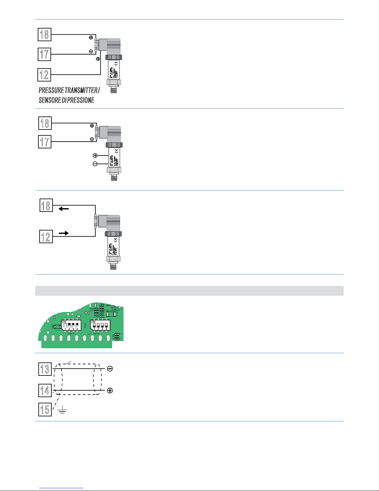
PRESSURE TRANSMITTER /
SENSORE DI PRESSIONE
P :0...100mbar
Pmax :3bar
T :0..70°C
OUT : 4...20mA
IN :9...33V DC
12
17
18
B
C
A
4...20mA
For linear signals 0/4..20 mA with three-wires sensors.
Comply with polarity:
A= Sensor supply
B= Sensor ground
C= Sensor output
External supply /
Alimentazione esterna
P :0...100mbar
Pmax :3bar
T :0..70°C
OUT : 4...20mA
IN :9...33V DC
PRESSURE TRANSMITTER /
SENSORE DI PRESSIONE
17
18
C
B
4...20mA
For linear signals 0/4..20 mA with external power supply
for sensor.
Comply with polarity:
C= Sensor output
B= Sensor ground
P :0...100mbar
Pmax :3bar
T :0..70°C
OUT : 4...20mA
IN :9...33V DC
18
12
C
A
PRESSURE TRANSMITTER /
SENSORE DI PRESSIONE
4...20mA
For linear signals in current 0/4..20 mA with two-wires
sensors.
Comply with polarity:
C= Sensor output
A= Sensor supply
5.1.d Serial input (only for ATR171-23ABC-T)
To enable the second analogue input, set the dip
switches as indicated in the figure.
In this configuration the second analogue input is not
available.
13
RS485
14
15
Shield/Schermo
Communication RS485 Modbus RTU.
For networks with more than five instruments supply in
low voltage.

12 ATR171 - User manual
5.1.e Relay outputs Q1, Q2, Q3
3
4
5
Q1
8A
230V
1/2HP
6
7
8
9
Q2
8A
230V
1/2HP
Q3
8A
230V
1/2HP
Contacts capacity:
8 A, 250 Vac, resistive charge 10
5
operations;
30/3 A, 250 Vac, cosφ= 0.3, 10
5
operations.
5.1.f Relay output Q4 (only for ATR171-14ABC)
10
11
Q4
5A
30V
1/8HP
Contacts capacity:
5 A, 30 Vac/dc, resistive 18x10
4
operations.

User manual - ATR171 13
5.1.g SSR output
SSR
10
11
SSR Command output 12 V / 30 mA.
To use SSR output it is necessary to set
channel 1 of DIP2 as indicated in the figure.
5.1.h Output mA / Volt (only for ATR171-23ABC-T)
10
11
mA
Analogue output in mA configurable as command (Par.
c.out
) or retransmission of process-setpoint (Par.
re t r.
).
To use SSR output it is necessary to set
channel 1 of DIP2 as indicated in the figure.
10
11
V
Analogue output in Volt configurable as command
(Par.
c.out
) or retransmission of process-setpoint (Par.
re t r.
).
To use SSR output it is necessary to set
channel 1 of DIP2 as indicated in the figure.
5.1.i Digital Input (only for ATR171-11/12/14-ABC)
12
13
+Vdc
DI
Digital Input (Par.
d Gt .i .
).

14 ATR171 - User manual
6 Display and keys functions
ATR171
FNC
PRGM
SET
C1
A1
C2
A2
TUN
A3
MAN
REM
RUN
C1
A1
C2
A2
TUN
A3
MAN
REM
RUN
1
3
4
7
26 5
9 8 10
1613 14
12 15
11
6.1 Numeric indicators (Display)
1
1234
Normally displays the process. During the configuration phase, it
displays the parameter being inserted.
2
1234
Normally displays the setpoint. During the configuration phase, it
displays the parameter value being inserted.
6.2 Meaning of Status Lights (Led)
3 C1
On when command output is active. For open / close logic: on
during valve opening.
4
C2 For open/ close logic: on during valve closing.
5
A1 On when alarm 1 is active.
6
A2 On when alarm 2 is active.
7
A3 On when alarm 3 is active.
8
MAN On when “Manual” function is active.
9
TUN On when controller is executing an auto-tuning cycle.
10
REM On when serial communication is in progress.
11
RUN On when counting of Timer function is active.

User manual - ATR171 15
6.3 Keys
12
• Increases main setpoint.
• In configuration mode allows to scroll and modify parameters.
• Press after SET key increases alarm setpoints or time value of
timer.
13
• Decreases main setpoint.
• In configuration mode allows to scroll and modify parameters.
• Press after SET key decreases alarm setpoints or time value of
timer.
14
SET
• Allows to visualize alarm setpoints or time value of Timer.
• In configuration mode allows to access the parameter to change
and confirm its modification.
15
FNC
• Allows to enter tuning launch, selection automatic / manual.
• In configuration mode operates as exit key (ESCAPE).
• If
U.M.C.P.
other then
Di s .
, it is possible to modify parameters of
pre-programmed cycle.
16
PRGM
• If pressed allows to enter configuration password.
• In configuration mode assigns at selected parameter a mnemonic
code or a number.
• Starts or stops timer counting.
• It allows to reset alarms if programmed for manual reset.
7 Dual input mode (only for ATR171-23ABC-T)
To enable second input it is necessary to set dip switches as indicated in the figure.
In this configuration some parameters
and functions are not available. For
exemple: RS485 serial, preprogrammed
cycle and soft-start function are desabled.

16 ATR171 - User manual
7.1 Selection of process value related to the command
output and to the alarms
When second input is enabled (par. 9
Sen .2
other than
di s .
) it is possible to choose
the process value to be related to command output, to alarms and to retransmission.
Following options are available:
•
Pro . 1
: Value read by input AI1;
•
Pro . 2
: Value read by input AI2;
•
Mean
: Mean between inputs AI1 and AI2;
•
di F F.
: Difference between inputs: AI1-AI2;
•
AbS. d .
: Difference between inputs AI1-AI2 as absolute value.
• Process related to command output must be set on parameter 15
c.Pro .
.
• Process related to alarms must be set on par. 34
A.1Pr.
for alarm 1, on par. 43
A. 2Pr.
for alarm 2 and on par. 52
A.3 P r.
for alarm 3.
• Value to retransmit must be set on par. 79
re t r.
.
It is possible to choose the visualization for display 2 on parameter 77
u.i.d.2
.
Mean and difference are available only if both inputs are configured for
temperature sensors.
7.2 Remote setpoint
It is possible to enable remote setpoint function setting
En .
on par. 16
rEM.S.
.
ATR171
FNC
PRGM
SET
PROBE
OUT
ATR171
ATR171
FNC
PRGM
SET
PROBE
OUT
ATR171
RT1
37383940414243
4445
293031323334
3536
28
19 20 21 22 232425
26 27
10 11 12 13 141516
17 18
1 2 3 4 567
8 9
46474849
4...20mA
0...10V
REMOTE SETPOINT
REMOTE SETPOINT
Control Loop
Control Loop
In this configuration the value read by one of the two inputs becomes the main
control setpoint:
• If par. 15
c.Pro .
is set as
P r o .1
, AI1 becomes the main process (command) and AI2
becomes the setpoint value;
• If par. 15
c.Pro .
is set as
P r o .1
, AI2 becomes the main process (command) and AI1
becomes the setpoint value.
Remote setpoint function works only with one of these two settings of par. 15
c.Pro .
.

User manual - AT R171 17
8 Controller functions
8.1 Modification of main and alarm setpoint value
Setpoint value can be modified from keyboard as follows:
1
Value on display 2 changes
Increase or decrease main
setpoint value
2
SET
Visualizes alarm setpoint on display
1
3
Value on display 2 changes
Increase or decrease alarm
setpoint value
8.2 Auto-tuning
Tuning procedure to calculate regulation parameters can be manual or automatic
and selected from parameter 24
tune
.
8.3 Manual Tuning
Manual procedure allows user more flexibility on deciding when to update
regulation parameters of P.I.D. algorithm.
Press FNC key until display 1 visualizes writing
tune
and display 2 visualizes
o FF
.
Pressing
display 2 visualizes
o n
. Led TUN switches on and procedure starts.
8.4 Automatic Tuning
Automatic tuning starts when the controller is switched-on or when setpoint value
has been modified over 35%. To avoid overshooting, the threshold where controller
calculates new P.I.D. parameters is determinated by setpoint value minus “Set
Deviation Tune” value (see parameter 25
s.d.tu.
).
To interrupt Tuning keeping the P.I.D. values unchanged, press key FNC until
display 1 visualizes writing
tune
and display 2 visualizes
o n
. Pressing
, display 2
visualizes
o FF
, led TUN switchs off and procedure ends.
Setting
once
on parameter 24
tune
autotuning procedure starts only once when
instrument is switched on: after calculating P.I.D. parameters parameter 24
tune
returns to
di s .
.
8.5 Automatic / manual regulation of % control output
This function allows to switch from automatic functioning to manual control of
output porcentage.
With parameter 71
au.ma.
, it is possible to select two modes.
1 The first selection (
en .
): pressing key FNC display 1 visualizes writing
p.---
,
while display 2 visualizes
auto
. Press
to select manual mode
man.
. With
and
change output percentage. To return to automatic mode with the same
procedure, select
auto
on display 2: led MAN switches on and operation returns
to automatic mode.
2 The second selection (
en.st.
): enables the same functioning, but with two
important variants:

18 ATR171 - User manual
• In case of power failure or after a switch-off , at restart both the manual
functioning and the previously fi xed output percentage value will be maintained.
• If during automatic functioning there is a sensor failure, controller will
automatically switch to manual mode while maintaining command output
percentage unchanged as generated by P.I.D. immediately before failure.
8.6 Soft-Start
At switch-on the controller follows a rising gradient expressed in units (ex. degree/
hour) to reach the setpoint.
The chosen rising gradient in Unit / Hour must be set on parameter 73
ri . G r .
; at next
switch-on the controller will execute Soft Start function.
Automatic and manual Tuning function cannot be enabled if Soft Start function is
active. In model ATR171-23ABC-T the Soft-Start function may be enabled only if
dip-switches are confi gured for serial communication (AI2 desabled).
8.7 Pre-programmed cycle
This function allows to program a simple working cycle on time basis, and can be
enabled setting
p r. cy .
on parameter 70
op.mo.
: process reaches setpoint1 according
to gradient set on parameter 73
Grad .
, then it reaches setpoint2 with the maximum
power.
Once reached setpoint2, process is hold for the time set on parameter 75
m a . ti .
.
At expiry, process reaches environmental temperature according to gradient set on
parameter 74
f a . G r.
and then command output is disabled and controller visualizes
stop
.
It is possible to handle Start/Stop also by digital input
It is also possible to modify parameters of pre-programmed cycle from user menu
setting parameter 76
u.m.c.p.
To start modifi cation, press FNC.
Setpoint
Setpoint 2
Max.
power
Setpoint 1
Hold
Natural cooling
Time
Gradient
Cycle starts at each switch-on of the
controller.
In model ATR171-23ABC-T the pre-programmed cycle function may be enabled only
if dip-switches are confi gured for serial communication (AI2 desabled).

User manual - ATR171 19
8.8 Memory Card (optional)
Parameters and setpoint values can be easily copied from one controller to others
using the Memory Card. Two modes are available:
1 With the controller connected to the power supply. Insert Memory card when
the controller is off. At switch-on display 1 visualizes
memo
and display 2 visualizes
----
(only if correct values are stored on Memory). Pressing
display 2 visualizes
Lo a d
. Confirm with FNC. Controller loads news values and restarts.
2 With the controller not connected to power supply. The memory card is
equipped with an internal battery with an autonomy of about 1000 uses.
Insert the memory card and press the programming button. When writing the
parameters, led turns red and on completing the procedure it turns to green. It is
possible to repeat the procedure without any particular attention.
Updating Memory Card
To update the memory card values, follow the procedure described in the first
method, setting display 2 to
----
so as not to load the parameters on controller
1
.
Enter configuration and change at least one parameter.
Exit configuration. Changes are saved automatically.
8.9 LATCH-ON function
For use with input
p o t .1
(potentiometer 6 KΩ) and
po t.2
(potentiometer 150 KΩ) and
with linear input (0..10 V, 0..40 mV, 0/4..20 mA), you can associate start value of the
scale (parameter 4
Lo . L.i .
) to the minimum position of the sensor and value of the
scale end (parameter 7
u P.L.i .
) to the maximum position of the sensor (parameter 8
La t c.
configured as
Std .
).
It is also possible to fix the point in which the controller will display 0 (however
keeping the scale range between
Lo . L.i .
and
u P.L.i .
)
using the “virtual zero” option by setting
u.0s t.
or
u.0in.
in parameter 8
La t c.
.
If you set
u.0in.
the virtual zero will reset after each activation of the tool;
if you set
u.0s t.
the virtual zero remains fixed once tuned.
To use the LATCH ON function configure as you wish the parameter
La t c.
2
.
For the calibration procedure refer to the following table:
Press Display Do
1
FNC
Exit parameters configuration.
Display 2 visualizes writing
La t c.
.
Place the sensor on minimum
operating value (corresponding
to
Lo . L.i .
).
2
Store value on minimum.
Display shows
Lo W
.
Place sensor on maximum
operating value (corresponding
to
u P.L.i .
).
1
If on activation the controller does not display
memo
it means no data have been saved on the
memory card, but it is possible to update values.
2
Calibration procedure starts by exiting configuration after parameter change.

20 ATR171 - User manual
Press Display Do
3
Store value on max.
Display shows
Hi G h
.
To exit standard proceeding press
FNC. For “virtual zero” setting,
place the sensor to zero point.
4
SET
Set the virtual zero. Display shows
ui rt.
. N.B.: If
u.0in.
is selected,
the procedure must be executed
at each start
To exit procedure press FNC.
8.10 Timer function
To enable a timer with time value selectable by the user, confi gurate parameter 60
tMrf
as follows:
•
mm.ss
: Timer with time base in seconds (mm.ss);
•
HH. m m
: Timer with time base in minutes (hh.mm).
To modify counting time duration, follow the steps below:
Press Display Do
1
SET
Press until
tM r.
is visualized on
display 1.
2
Value on display 2 changes
Increase or decrease time value of
selected Timer.
To start or stop timer press PRGM or act via digital input if parameter 72
d Gt .i .
is
selected as
t m r.i .
.
During counting led RUN is on and display 2 visualizes decrementing time.
At expiry of Timer led RUN turns off and display 2 blinks showing time value until
a key is pressed.
8.11 Digital input functions (only for ATR171-11/12/14ABC)
Select chosen function on parameter 72
d Gt .i .
(par. 70
op.mo.
, must be set on
Co n t.
).
•
st.st.
: Start of Pre-programmed cycle (See par. 8.7);
•
rn.n.o.
o
rn.n.c.
: enables regulation;
•
L.c.n.o.
o
L.c.n.c.
: (Hold Function) allows to lock sensors reading when digital
input is active. It’s useful when measure oscillates on less signifi cant values.
During hold phase display 2 blinks showing
La t c.
.
•
tune
: enable / desables Tuning by digital input if par. 24
tune
is set on
Man.
.
•
a.ma.i.
o
a.ma.c.
: switch from automatic to manual mode if parameter 71
Au.Ma.
is
set on
en .
or
en.st.
.

User manual - ATR171 21
•
t m r.i .
: start / stop of Timer function (See par. 8.10);
The parameter 70
op.mo.
, enable other functions to use digital imput:
•
p r. cy .
: Pre-programmed cycle (See par. 8.7);
•
2t.s ., 2t . s .i, 3 t . s .i, 4 t . s .i
: It’s possible to use digital input for setpoint change
function. This mode allows to recall 2 to 4 thresholds / setpoints by external
button without pressing the arrow keys during operation. The setpoints can be
entered during operation pressing SET key.
8.12 Heating-Cooling P.I.D.
ATR171 is suitable also for also for applications requiring a combined heating-cooling P.I.D. action.
Command output has to be configured as heating P.I.D. (
Act.t.
=
hea t
and
p . b .
greater than 0), and one of alarms (
a L. 1, a L. 2
or
a L. 3
) has to be configured as
cooL
.
Command output must be connected to actuator responsible for heating action,
while alarm will control the cooling action.
Parameters to configure for Heating P.I.D. are:
Act.t.
=
hea t
Command output action type (Heating);
p. b .
: Proportional band Heating;
t.i.
: Integral time Heating and cooling;
t. d .
: Derivative time Heating and cooling;
t. c.
: Cycle time Heating.
Configuration parameters for Cooling P.I.D. are (example: action associated to alarm 1):
aL. 1
=
co o L
Alarm 1 selection (Cooling);
p.b.m.
: Proportional band multiplier;
ou.d.b.
: Overlapping / dead band;
co.t.c.
: Cycle time Cooling.
Parameter
p.b.m.
(that ranges from 1.00 to 5.00) sets the proportional band for
cooling action, according to the formula here below:
Proportional band for cooling action =
p. b .
x
p.b.m.
.
In this way it is possible to have a proportional band for cooling action that will be
equal to heating proportional band if
p.b.m.
= 1.00, or 5 times greater if
p.b.m.
= 5.00.
Integral time and derivative time are the same for both actions.
Parameter
ou.d.b.
sets the percentage overlapping between the two actions. For
installations where heating and cooling output cannot be activated at the same
time, a dead band will be configured (
ou.d.b.
≤ 0), vice versa an overlapping will be
configured (
ou.d.b.
> 0). Figure here below shows an example of double action P.I.D.
(heating-cooling) with
t.i.
= 0 and
t. d .
= 0.

22 ATR171 - User manual
1
ACTIVE
ACTIVE
SPV
PV
x = COOL
< 0
(HEAT)
COMMAND OUTPUT (HEAT)
ALARM OUTPUT (COOL)
2
ACTIVE
ACTIVE
SPV
PV
x = COOL
x = COOL
< 0
= 0
(HEAT)
(HEAT)
COMMAND OUTPUT (HEAT)
ALARM OUTPUT (COOL)
COMMAND OUTPUT (HEAT)
ALARM OUTPUT (COOL)
SPV
PV
ACTIVE
ACTIVE
3
ACTIVE
ACTIVE
SPV
PV
x = COOL
x = COOL
x = COOL
< 0
= 0
> 0
(HEAT)
(HEAT)
(HEAT)
COMMAND OUTPUT (HEAT)
ALARM OUTPUT (COOL)
COMMAND OUTPUT (HEAT)
ALARM OUTPUT (COOL)
COMMAND OUTPUT (HEAT)
ALARM OUTPUT (COOL)
SPV
PV
ACTIVE
ACTIVE
SPV
PV
ACTIVE
ACTIVE
Parameter
co.t.c.
has the same meaning of cycle time for heating action
t. c.
.
Parameter
c o o . F.
(Cooling Fluid) pre-selects the proportional band multiplier
p.b.m.
and the cooling P.I.D. cycle time
co.t.c.
according to cooling fluid type:
co o . f.
Cooling fluid type
p.b.m.
co.c.t.
Ai r
Air 1.00 10
oi L
Oil 1.25 4
H2o
Water 2.50 2
Once parameter
c o o . F.
has been selected, the parameters
p.b.m. , ou.d.b.
and
co.t.c.
can be however modified.

User manual - ATR171 23
9 Serial communication (only for ATR171-23ABC-T)
To enable serial input set the dip switchs as indicated in the figure:
In this configuration mode, parameters
and functioning related to double
analogue input are not available.
9.1 Modbus RTU
ATR171-23ABC-T is provided with RS485 and can receive/broadcast data via
MODBUS-RTU protocol. Device can be configured only as Slave. This function allows
to control multiple controllers connected to a supervisory system (SCADA).
Each instrument will answer to a Master query only if contains same address as on
parameter 84
SL. a d .
. Allowed addresses are from 1 to 254 and there should not
be controllers with the same address on the same line. Address 255 can be used
by the Master to communicate with all connected equipments (broadcast mode),
while with 0 all devices receive command, but no answer is expected. ATR171 can
introduce an answer delay (in milliseconds) to Master request. This delay has to be
set on parameter 85
Se. d e.
. At each parameters modification, instrument stores
values in EEPROM memory (100000 writing cycles), while setpoints are stored with a
delay of 10 seconds after last modification.
N.B.: Modifications made to Words different from those described in the following
table can lead to instrument malfunction.
Modbus RTU protocol features
Baud-rate
Selectable on parameter 83
bd. rt.
4.8 k
4800 bit/sec
9.6 k
9600bit/sec
19.2k
19200bit/sec
28.8 k
28800bit/sec
38 .4 k
38400bit/sec
57.6 k
57600bit/sec
Format 8, N, 1 (8 bit, no parity, 1 stop)
Supported
functions
WORD READING (max 20 word) (0x03, 0x04)
SINGLE WORD WRITING (0x06)
MULTIPLE WORDS WRITING (max 20 word) (0x10)
Looking at the table here below it is possible to find all available addresses and
functions:
RO = Read Only R/W = Read / Write WO = Write Only

24 ATR171 - User manual
Modbus
address
Description
Read
Write
Reset
value
0 Device type RO EEPROM
1 Sotware version RO EEPROM
5 Slave address R/W EEPROM
6 Boot version RO EEPROM
50 Automatic addressing WO 51 Installation code comparison WO -
500
Loading Default values:
9999 restore all values
9998 restore all values except for baud-rate and
slave address
9997 restore all values except for baud-rate
9996 restore all values except for slave address
R/W 0
1000
Process (degrees with tenths of degree for
temperature sensors; digits for linear sensors)
RO ?
1001 Setpoint 1 R/W EEPROM
1002 Setpoint 2 R/W EEPROM
1003 Setpoint 3 R/W EEPROM
1004 Setpoint 4 R/W EEPROM
1005 Alarm 1 R/W EEPROM
1006 Alarm 2 R/W EEPROM
1007 Alarm 3 R/W EEPROM
1008 Setpoint gradient RO EEPROM
1009
Relay status (0 = Off, 1 = On)
Bit 0 = SSR Bit 2 = Relay Q2
Bit 1 = Relay Q1 Bit 3 = Relay Q3
RO 0
1010 Heating output percentage (0-10000) RO 0
1011 Heating output percentage (0-10000) RO 0
1012
Alarms status (0 = None, 1 = Active)
Bit 0 = Alarm 1
Bit 1 = Alarm 2
Bit 2 = Alarm 3
RO 0
1013
Manual reset: write 0 to reset all alarms.
In reading (0 = Not resettable, 1 = Resettable):
Bit 0 = Alarm 1
Bit 1 = Alarm 2
Bit 2 = Alarm 3
WO 0
1014
Error flags
Bit 0 = Eeprom writing error
Bit 1 = Eeprom reading error
Bit 2 = Cold juntion error
Bit 3 = Error AI1 (probe 1)
RO 0

User manual - ATR171 25
Modbus
address
Description
Read
Write
Reset
value
1024
Bit 4 = Error AI2 (probe 2)
Bit 5 = Generic error
Bit6 = Hardware error
Bit 7 = Missing calibration error
Bit 8 = Incongruous control parameters
Bit 9 = Incongruous alarm parameters
Bit 10 = Incongruous retransmission par.
Bit 11 = Incorrect visualization parameters error
Bit 12 = Incorrect remote setpoint par. error
RO 0
1015 Cold junction temperature (with decimal point) RO ?
1016
Start / Stop
0 = Controller in STOP 1 = Controller in START
R/W 0
1017
Lock conversion ON/OFF
0 = Lock conversion off 1 = Lock conversion on
R/W 0
1018
Tuning ON/OFF
0 = Tuning off 1 = Tuning on
R/W 0
1019
Automatic / Manual selection
0 = Automatic 1 = Manual
R/W 0
1020 OFF LINE* time (milliseconds) R/W 0
1100 Process with decimal point RO ?
1101 Setpoint 1 with decimal point RW EEPROM
1102 Setpoint 2 with decimal point RW EEPROM
1103 Setpoint 3 with decimal point RW EEPROM
1104 Setpoint 4 with decimal point R/W EEPROM
1105 Alarm 1 with decimal point R/W EEPROM
1106 Alarm 2 with decimal point RW EEPROM
1107 Alarm 3 with decimal point RW EEPROM
1108 Setpoint gradient with decimal point RO EEPROM
1109 Percentage heating output (0-1000) R/W 0
1110 Percentage heating output (0-100) RW 0
1111 Percentage cooling output (0-1000) RO 0
1112 Percentage cooling output (0-100) RO 0
2001 Parameter 1 R/W EEPROM
... ... ... ...
2085 Parameter 85 R/W EEPROM
4001 Parameter 1** R/W EEPROM
... ... ... ...
4085 Parameter 85 R/W EEPROM
* If it is 0, control is desabled. If it is different from 0, it is “maximum time that can elapse between two
pollings before the controller goes off-line”. If it goes Off-line, the controller goes to Stop mode, the control
output is desabled, but the controllers keeps alarms activated.
** Parameters changed using serial address from 4001 to 4085 are saved in eeprom only after 10’’ after the
last writing of parameters.

26 ATR171 - User manual
10 Configuration
10.1 Modify configuration parameters
For configuration parameters see next paragraph.
Press Display Do
1
PRGM
for 3s.
Display 1 shows
0.000
with 1st
digit flashing, while display 2
shows
Pass
.
2
Modify flashing digit and move to
next digit with SET.
Enter password:
1234
.
3
PRGM
to conf.
Display 1 shows first parameter
and second display shows its
value.
4
Scroll parameters.
5
PRGM
Allows to pass from mnemonic
parameter code to the numeric
one and viceversa.
6
SET
Allows parameter modification
(display 2 flashes).
7
Increases or decreases visualized
value.
Introduce new data that will be
stored when keys are released.
8
SET
Confirms data entering (display 2
stops flashing).
To change another parameter
return to point 4.
9
FNC
End of parameters modification.
Controller esc from programming
mode.
10.2 Loading default values
This procedure allows to restore default settings of the instrument.
Press Display Do
1
PRGM
for 3s.
Display 1 visualizes
0.000
with
1st digit blinking, while display 2
shows
pass
.
2
Changes blinking digit and moves
to the next one with SET.
Enter password:
9999
.
3
PRGM
to confirm
Device loads default settings.
Switch the instrument off
and on.

User manual - ATR171 27
11 Table of configuration parameters
The following table includes all parameters. Some of them will not appear on the
models which are not provided with relevant hardware data.
1
c.out
Command Output
Command output type selection
c. o1
Default
c.uaL
Command of open-loop valves
c.ss r
SSR command (voltage)
c.4 . 2 0
Do not use this option for process retransmission
c.0.20
Do not use this option for process retransmission
c.0.10
Do not use this option for process retransmission
ATR17111ABC
Command Alarm 1
c. o1
Q1 SSR
c.uaL.
Q1 (open) - Q2 (close) -
c.ss r
SSR Q1
ATR17112ABC
Command Alarm 1 Alarm 2
c. o1
Q1 Q2 SSR
c.uaL.
Q1 (open) - Q2 (close) SSR -
c.ss r
SSR Q1 Q2
ATR17114ABC
Command Alarm 1 Alarm 2 Alarm 3
c. o1
Q1 Q2 Q3 Q4
c.uaL.
Q1 (open) - Q2 (close) Q1 Q4 -
ATR17123ABC
Command Alarm 1 Alarm 2 Alarm 3
c. o1
Q1 Q2 Q3 SSR
c.uaL.
Q1 (open) - Q2 (close) Q1 SSR -
c.ss r
SRR Q1 Q2 Q3
c.4 . 2 0
4...20mA Q1 Q2 Q3
c.0.20
0...20mA Q1 Q2 Q3
c.0.10
0...10V Q1 Q2 Q3

28 ATR171 - User manual
2
s e n .1
Sensor 1
Analogue input configuration / sensor selection (AI1).
di s .
Disabled (Default)
tc. k
Tc-K -260..1360 °C
tc. s
Tc-S -40..1760 °C
tc. r
Tc-R -40..1760 °C
tc. J
Tc-J -200..1200 °C
pt
PT100 -200..600 °C
p t 1
PT100 -200..140 °C
ni
NI100 -60..180 °C
ntc
NTC10K -40..125 °C
ptc
PTC1K -50..150 °C
p t5
PT500 -100..600 °C
p t 1k
PT1000 -100..600 °C
0. 10
0..10 Volt
0. 20
0..20 mA
4. 20
4..20 mA
0. 40
0..40 mVolt
p o t .1
Potentiometer max 6 Kohm (full scale)
po t.2
Potentiometer max 150 Kohm (full scale)
3
d. p.
Decimal Point 1
Select type of visualized decimal point for Analogue Input 1
0
Default
0.0
1 decimal
0.00
2 decimals
0.000
3 decimals
4
LOL.i
Lower Linear Input 1
AI1 lower range limit only for linear signals
-999..+9999 digit
3
(degrees if temperature), Default: 0
5
u p L.i
Upper Limit Input 1
AI1 upper limit setpoint
-999..+9999 digit
3
(degrees if temperature), Default: 1750
6
o . c a .1
Offset Calibration 1
Offset AI1 calibration. Value added/subtracted to visualized process value
(normally used to correct ambient temperature value)
-999..+1000 digit
3
for linear sensors and potentiometers.
-99.9..+100.0 tenths for temperature sensors, Default: 0.0.
3
The display of the decimal point depends on the setting of parameter
sen
. and
d. p. 1
or
sen .2
and
d . p. 2.

User manual - ATR171 29
7
G . c a .1
Gain Calibration 1
AI1 gain calibration. % value multiplied with displayed value to calibrate process value.
-99.9%..+100.0%, Default: 1000
Example: to correct a scale 0...1000°C which is showing 0...1010°C, enter -1.0 on
this parameter
8
L t c .1
Latch-On
Automatic setting of limits for linear input.
di s .
Disabled. Default
std.
Standard
u.0s t.
Virtual Zero Stored (See par. 8.9)
u.0in.
Virtual Zero Initialized (See par. 8.9)
9
sen .2
Sensor 2
Analogue input 2 configuration / sensor selection AI2. Select dip-switches as
indicated on 5.1.c.
di s .
Disabled (Default)
tc. k
Tc-K -260..1360 °C
tc. s
Tc-S -40..1760 °C
tc. r
Tc-R -40..1760 °C
tc. J
Tc-J -200..1200 °C
pt
PT100 -200..600 °C
p t 1
PT100 -200..140 °C
ni
NI100 -60..180 °C
ntc
NTC10K -40..125 °C
ptc
PTC1K -50..150 °C
p t5
PT500 -100..600 °C
p t 1k
PT1000 -100..600 °C
10
d . p. 2
Decimal Point 2
Select decimal type visualized for analogue input 2.
0
Default
0.0
1 Decimal
11
o. ca .2
Offset Calibration 2
Offset AI1 calibration. Number added to visualized process value (normally
correcting environment temperature value) (only on ATR171-24ABC-T )
-99.9..+100.0 tenths of degree. Default: 0.0
12
G. ca .2
Gain Calibration 2
AI2 Gain calibration. % Value multiplied with displayed value to calibrate process value.
-99.9%..+100.0%, Default: 1000
ex: if input value is 0..1010°C and visualization is expected to be 0..1000°C set
parameter as -1.0

30 ATR171 - User manual
13
Lo .L. s .
Lower Limit Setpoint
AI lower limit selectable for setpoint.
-999..+9999 digit4 (degrees if temperature), Default: 0.
14
u p. L. s .
Upper Limit Setpoint 2
AI2 upper limit setpoint.
-999..+9999 digit
4
(degrees i f temperature), Default: 1750.
15
c. pro .
Command Process
Selects process value related to command output and visualized on display 1.
This determinates which is the primary process
p r o .1
Process 1 (Default)
pro.2
Process 2
Mean
Process mean
di f f.
Processes difference
abs.d.
Processes difference as absolute value
16
rem .s .
Remote Setpoint
Enables remote setpoint. Command setpoint is the secondary process. It works
if
p r o .1
or
pro.2
is selected on parameter
c. pro .
.
di s .
Disabled (Default)
en.
Enabled
17
act. t.
Command Action Type
Regulation type for command output
Heat
Heating (N.O.) (Default)
coo l
Cooling (N.C.)
H.o.o.s.
Lock command above SPV. Example: command output is not activated
when reaching setpoint, even with P.I.D. value other than 0.
18
c. Hy.
Command Hysteresis
Hysteresis in ON / OFF or dead band in P.I.D.
-999..+999 digit
4
(tenth of degree if temperature), Default: 0.0.
19
c. re.
Command Rearmament
Type of reset for contact of command output (always automatic in P.I.D.
functioning)
a. re.
Automatic Reset (Default)
m. re.
Manual Reset by keyboard.
m. re.s .
Manual reset stored. (keeps relay status also after an eventual power
failure)
4
The display of the decimal point depends on the setting of parameter
sen
. and
d. p. 1
or
sen .2
and
d . p. 2.

User manual - ATR171 31
20
c. se.
Command State Error
Contact state for command output in case of error
c. o.
Open contact (Default)
c. c.
Closed contact
21
c. Ld.
Command Led
Defines led OUT1 state corresponding to relevant contact
c. o.
ON with open contact
c. c.
ON with closed contact (Default)
22
c. d e.
Command Delay
Command delay (only in ON / OFF functioning). (In case of valves it works also in
P.I.D. and represents delay between opening and closure of two contacts).
-600..+600 seconds (tenth of second in case of servo valve).
Negative: delay when turning off.
Positive: delay when turning on.
Default: 0.
23
c. s. p.
Command Setpoint Protection
Allows/prevents changes to command setpoint value by keyboard
free
Modification allowed (Default)
Lo c k
Protected
24
tune
Tune
Autotuning type selection
di s .
Disabled (Default)
auto
Automatic (P.I.D. parameters calculation at each activation and / or
each change)
man.
Manual (launch by keyboards or by digital input)
once
Once (P.I.D. parameters calculation only at first start)
25
s.d.tu.
Setpoint Deviation Tune
Selects deviation from command setpoint as threshold used by autotuning to
calculate P.I.D. parameters
0..5000 digit
5
(tenth of degree if temperature), Default: 10.0.
26
p. b .
Proportional Band
Process inertia in units (example: °C if temperature)
0 ON / OFF if also
t.i .
is equal to 0 (Default).
1..9999 digit
5
(tenth of degree if temperature).
5
The display of the decimal point depends on the setting of parameter
sen
. and
d. p. 1
or
sen .2
and
d . p. 2.

32 ATR171 - User manual
27
t .i .
Integral Time
Process inertia in seconds
0.0..999.9 seconds. 0 integral disabled, Default: 0
28
t.d .
Derivative Time
Normally ¼ of integral time.
0.0..999.9 seconds. 0 derivative disabled, Default: 0
29
t. c.
Cycle Time
Cycle time (for P.I.D. on remote control switch 10 / 15 sec., for P.I.D. on SSR 1 sec.)
or servo time (value declared by servo-motor manufacturer).
0.1..300.0 seconds, Default: 10
30
L.L. o . p.
Lower Limit Output Percentage
Select minimum value for command output percentage.
0..100%, Default: 0%.
Example: with
c.out
selected as 0...10 V and
L.L. o . p
set at 10%, command output
can change from a min. of 1 V to a max. of 10 V.
31
u.L.o.p.
Upper Limit Output Percentage
Selects maximum value for command output percentage.
0..100%, Default: 100%.
Example:
c.out
selected as 0...10 V and
u.L.o.p.
selected as 90%, command
output may vary between 0V and max. 9 V
32
d eG r.
Degree
Select degree type.
c
Centigrade (Default)
f
Fahrenheit
33
AL. 1
Alarm 1
Alarm 1 selection. Alarm intervention is correlated to AL1 (See par. 12)
di s .
Disabled (Default)
a . aL.
Absolute alarm, referring to process
b . aL.
Band alarm
H.d.aL.
Upper deviation alarm
L. d . a L.
Lower deviation alarm
a . c. A L.
Absolute alarm, referring to command setpoint
st.Al.
Status alarm (active in Run / Start)
co o L.
Cooling action
t.run
Timer run
t.end
Timer end

User manual - ATR171 33
34
a .1 . p r .
Alarm 1 Process
Select value correlated to alarm 1
p r o .1
Process 1 (Default)
pro.2
Process 2
Mean
Processes mean
di f f.
Processes difference
abs.d
. Processes difference as absolute value
35
a .1 . s . o .
Alarm 1 State Output
Alarm 1 output contact and type of action
n . o . s
. (N.O. start) Normally open, active from start (Default)
n . c. s.
(N.C. start) Normally closed, active from start
n . o . t.
(N.O. threshold) Normally open, active from alarm reaching
6
n . c. t.
(N.C. threshold) Normally closed, active from alarm reaching
6
36
a .1 . H y .
Alarm 1 Hysteresis
-999..+999 digit
7
(tenths of degree if temperature), Default: 0.0.
37
a1 . r e .
Alarm 1 Rearmament
Type of reset for contact of alarm 1
a. re.
Automatic Reset (Default)
m. re.
Manual Reset by keyboard
m. re.s .
Manual reset stored (keeps relay status also after an eventual power
failure)
38
a .1 . s . e .
Alarm 1 State Error
Contact status for alarm 1 output in case of error
c. o.
Open contact (Default)
c. c.
Closed contact
39
a.1.Ld.
Alarm 1 Led
Defines led A1 status corresponding to relevant contact
c. o.
ON with open contact
c. c.
ON with closed contact (Default)
40
a .1 . d e .
Alarm 1 Delay
-600..+600 seconds.
Negative: delay at exit from alarm.
Positive: delay at starting of alarm.
Default: 0.
6
On activation, the output is inhibited if the controller is in alarm mode. Activates only if alarm
condition reappers, after that it was restored.
7
The display of the decimal point depends on the setting of parameter
sen
. and
d. p. 1
or
sen .2
and
d . p. 2.

34 ATR171 - User manual
41
a .1 . s . p .
Alarm 1 Setpoint Protection
Alarm 1 set protection. Does not allow the user to change setpoint
free
Modification allowed (Default)
Lo c k
Protected
Hi d e
Protected and not visualized
42
aL. 2
Alarm 2
Alarm 2 selection. Alarm intervention is associated to AL2 (See par. 12)
dis. Disabled (Default)
a . aL.
Absolute alarm, referring to process
b . aL.
Band alarm
H.d.aL.
Upper deviation alarm
L. d . a L.
Lower deviation alarm
a.c.aL.
Absolute alarm, referring to command setpoint
s t. a L.
Status alarm (active in Run / Start)
cooL
Cooling action
t.run
Timer run
t.end
Timer end
43
a . 2. p r.
Alarm 2 Process
Selects value related to alarm 2
p r o .1
Process 1 (Default)
pro.2
Process 2
mean
Processes mean
di f f.
Processes difference
abs.d.
Processes difference as absolute value
44
a .2. s . o .
Alarm 2 State Output
Alarm 2 output contact and type of action
n . o . s.
(N.O. start) Normally open, active from Start (Default)
n . c. s.
(N.C. start) Normally closed, active from Start
n . o . t.
(N.O. threshold) Normally open, active from alarm reaching
8
n . c. t.
(N.C. threshold) Normally closed, active from alarm reaching
8
45
a.2.Hy.
Alarm 2 Hysteresis
-999..+999 digit
9
(tenth of degree if temperature), Default: 0.0.
8
On activation, the output is inhibited if the controller is in alarm mode. Activates only if alarm
condition reappers, after that it was restored.
9
The display of the decimal point depends on the setting of parameter
sen
. and
d. p. 1
or
sen .2
and
d . p. 2.

User manual - ATR171 35
46
a .2. re.
Alarm 2 Rearmament
Type of reset for alarm 2 contact
a. re.
Automatic Reset (Default)
m. re.
Manual Reset by keyboard
m. re.s .
Manual reset stored (keeps relay status also after an eventual power
failure)
47
a .2. s . e.
Alarm 2 State Error
Contact status for alarm 2 output in case of error
c. o.
Open contact (Default)
c. c.
Closed contact
48
a.2.Ld .
Alarm 2 Led
Defines led A2 status corresponding to relevant contact
c. o .
ON with open contact
c. c.
ON with closed contact (Default)
49
a .2. d e
. Alarm 2 Delay
Ritardo allarme 2
-600..+600 seconds.
Negative: delay at exit from alarm
Positive: delay at starting of alarm. Default: 0.
50
a .2. s . p.
Alarm 2 Setpoint Protection
Alarm 2 set protection. Does not allow the user to change set value
free
Modification allowed (Default)
Lo c k
Protected
Hi d e
Protected and not visualized
51
aL. 3
Alarm 3
Alarm 3 selection. Alarm intervention is associated to AL3 (See par. 12)
dis. Disabled (Default)
a . aL.
Absolute alarm, referring to process
b . aL.
Band alarm
H.d.aL.
Upper deviation alarm
L. d . a L.
Lower deviation alarm
a.c.aL.
Absolute alarm, referring to command setpoint
s t. a L.
Status alarm (active in Run / Start)
cooL
Cooling action
t.run
Timer run
t.end
Timer end

36 ATR171 - User manual
52
a .3. p r.
Alarm 3 Process
Selects value correlated to alarm 3
p r o .1
Process 1 (Default)
pro.2
Process 2
mean
Processes mean
di f f.
Processes difference
abs.d.
Processes difference as absolute value
53
a .3.s . o .
Alarm 3 State Output
Alarm 3 output contact and type of action
n . o . s.
(N.O. start) Normally open, active from start (Default)
n . c. s.
(N.C. start) Normally closed, active from start
n . o . t.
(N.O. threshold) Normally open, active from alarm reaching
10
n . c. t.
(N.C. threshold) Normally closed, active from alarm reaching
10
54
a .3.HY.
Alarm 3 Hysteresis
-999..+999 digit
11
(tenths of degree if temperature), Default: 0.0.
55
a .3. re.
Alarm 3 Rearmament
Type of reset for alarm 3 contact
a. re.
Automatic Reset (Default)
m. re.
Manual Reset by keyboard
m. re.s .
Manual reset stored. (keeps relay status also after an eventual power
failure)
56
a .3.s . e.
Alarm 3 State Error
Contact status for alarm 3 output in case of error
c. o.
Open contact (Default)
c. c.
Closed contact
57
a.3.Ld.
Alarm 3 Led
Defines led A3 status corresponding to relevant contact
c. o .
ON with open contact
c. c.
ON with closed contact (Default)
58
a .3. d e.
Alarm 3 Delay
-600..+600 seconds.
Negative: delay at exit from alarm.
Positive: delay at starting of alarm. Default: 0.
10
On activation, the output is inhibited if the controller is in alarm mode. Activates only if alarm
condition reappers, after that it was restored.
11
The display of the decimal point depends on the setting of parameter
sen
. and
d. p. 1
or
sen .2
and
d . p. 2.

User manual - ATR171 37
59
a .3.s . p.
Alarm 3 Setpoint Protection
Alarm 3 set protection. Does not allow the user to change set value
free
Modification allowed (Default)
Lo c k
Protected
Hi d e
Protected and not visualized
60
tm rf
Timer functions
Enabling timer function and select time base (See par. 8.10)
di s .
(Default)
mm.ss
Timer with time base in seconds
HH. m m
Timer with time base in minutes
63
co o . f.
Cooling Fluid
Type of refrigerant fluid for heating / cooling P.I.D.
ai r
Air (Default)
oi L
Oil
H2o
Water
64
p.b.m.
Proportional Band Multiplier
Proportional band for cooling action is given by parameter 18 multiplied for this
parameter
1.00..5.00
Default: 1.00
65
ou.d.b.
Overlap / Dead Band
Dead band combination for heating / cooling P.I.D.
-20.0..50.0%.
Negative: Dead band.
Positive: overlap.
Default: 0
66
co.t.c.
Cooling Cycle Time
Cycle Time for Cooling output
1..300 seconds
Default: 10
67
c. fLt.
Conversion Filter
ADC Filter: number of sensor readings to calculate mean that defines process
value. NB: When readings increase, control loop speed slows down
di s .
Disabled
2. s . m .
2 Samples Mean (Mean with 2 samples)
3. s. m .
3 Samples Mean
4. s . m .
4 Samples Mean

38 ATR171 - User manual
5. s. m .
5 Samples Mean
6. s. m .
6 Samples Mean
7. s . m .
7 Samples Mean
8. s. m .
8 Samples Mean
9. s. m .
9 Samples Mean
10.s. m .
10 Samples Mean (Default)
11 . s . m .
11 Samples Mean
12. s . m .
12 Samples Mean
13.s . m .
13 Samples Mean
14.s . m .
14 Samples Mean
15.s . m .
15 Samples Mean
68
c. frn .
Conversion Frequency
Sampling frequency of digital / analogue converter.
NB: Increasing the conversion speed will slow down reading stability (example:
for fast transients, as the pressure, it is advisable to increase sampling frequency)
242H.
242 Hz (Maximum speed conversion)
123H.
123 Hz
62 H.
62 Hz
62 H.
50 Hz
39 H.
39 Hz
33.2H.
33.2 Hz
19.6H.
19.6 Hz
1 6 .7 H .
16.7 Hz (Default) Ideal for filtering noises 50 / 60 Hz
12.5H.
12.5 Hz
10 H.
10 Hz
8.33H.
8.33 Hz
6.25H.
6.25 Hz
4 .1 7 H .
4.17 Hz (Minimum speed conversion)
69
u . fLt.
Visualization Filter
Slow down the update of process value visualized on display, to simplify reading
di s .
Disabled (maximum speed of display update)
p t cH
Pitchfork filter (First order filter with pitchfork) > Default.
fi . o r.
First order
f.or.p.
First order with pitchfork
2. s . m .
2 Samples Mean
3. s. m .
3 Samples Mean
4. s . m .
4 Samples Mean
5. s. m .
5 Samples Mean
6. s. m .
6 Samples Mean
7. s . m .
7 Samples Mean)
8. s. m .
8 Samples Mean)
9. s. m .
9 Samples Mean
10.s . m .
10 Samples Mean (Maximum slow down of display update)

User manual - ATR171 39
70
op.mo.
Operating mode
Selects operating mode. In model ATR171-23ABC-T, this parameter is visible only
if dip-switches are configured for serial communication (AI2 desabled).
co n t.
Controller (Default)
p r. cy .
Programmed Cycle
2t.s .
2 Setpoints Switch
2t . s .i .
2 Setpoints Switch Impulsive
3 t . s .i .
3 Setpoints Switch Impulsive
4 t . s .i .
4 Setpoints Switch Impulsive
71
au.ma.
Automatic / Manual
Enables automatic / manual selection
di s .
Disabled (Default)
en.
Enabled
en.st.
Enabled with memory
72
d G t.i .
Digital Input
(par. 70 selection must be
co n t.
or
p r. cy .
). In model ATR171-23ABC-T, this
parameter is visible only if dip-switches are configured for serial communication
(AI2 desabled).
di s .
Disabled (Default: 0)
st.st.
Start / Stop
rn.n.o.
Run N.O. (enables regulation with N.O. contact)
rn.n.c.
Run N.C. (enables regulation with N.C. contact)
L.c.n.o.
Lock conversion N.O. (stop conversion and display value with N.O.)
L.c.n.c.
Lock conversion N.C. (stop conversion and display value with N.C.)
tu n e
Manual Tune (by digital input)
a.ma.i.
Automatic / Manual Impulse
a.ma.c.
Automatic / Manual Contact
t m r.i .
Impulse Start timer
73
ri . G r .
Rising Gradient
Rising gradient for Soft-Start or pre-programmed cycle. In model ATR17123ABC-T, this parameter is visible only if dip-switches are configured for serial
communication (AI2 desabled).
0 Disabled.
1..9999 Digit/hour
12
(degrees/hour with decimal visualization if temperature),
Default: 0.

40 ATR171 - User manual
74
faGr
Falling Gradient
Falling gradient for pre-programmed cyle. In model ATR171-23ABC-T, this
parameter is visible only if dip-switches are configured for serial communication
(AI2 desabled).
0 Disabled.
1..9999 Digit/hour
12
(degrees/hour with decimal visualization if temperature),
Default: 0.
75
m a . ti .
Maintenance Time
Holding time for pre-programmed cycle. In model ATR171-23ABC-T, this
parameter is visible only if dip-switches are configured for serial communication
(AI2 desabled).
00.00-24.00 hh.mm, Default: 00.00
76
u.m.c.p.
User Menu Cycle Programmed
Allows to modify rise gradient, falling and maintenance time from user menu,
when pre-programmed cycle is selected. To start modification of parameters
press FNC key. In model ATR171-23ABC-T, this parameter is visible only if
dip-switches are configured for serial communication (AI2 desabled).
di s .
Disabled (Default)
ri . G r .
Rising Gradient
m a . ti .
Maintenance Time
r.G.m.t.
Rising Gradient and Maintenance Time
faGr
Falling Gradient
r.F. G . r.
Rising and Falling Gradient
f.G.m.t.
Falling Gradient and Maintenance Time
a LL
All
77
ui . d . 2
Visualization Display 2
Set visualization on display 2
c.spu .
Command Setpoint (Default)
p r o .1
Process 1
pro .2
Process 2
mean
Processes mean
di f f.
Processes difference
abs.d.
Processes difference as absolute value
78
ui . t y .
Visualization Type
Set visualization type on display
std.
Display 1 process + Display 2 as
ui . d .2
(Default)
d.2.Hi .
Display 1 process + Display 2 as
ui . d .2
hidden after 3 sec.
suap
Display 1 as
ui . d .2
+ Display 2 process
s. d .2.H.
Display 1 as
ui . d .2
+ Display 2 process hidden after 3 sec.

User manual - ATR171 41
79
re t r.
Retransmission
Retransmission for output 0..10 V or 0/4..20 mA. Parameters 81 and 82 defines
upper/lower limit of scale
di s .
Disabled (Default)
c.spu .
Command Setpoint
p r o .1
Process 1
pro.2
Process 2
mean
Processes Mean
di f f.
Processes Difference
abs.d.
Processes Difference as absolute value
80
re.ty .
Retransmission Type
Select retransmission type
0 -1 0
0..10 Volt (Default)
0-20
0..20 mA
4-20
4..20 mA
81
Lo .L. r.
Lower Limit Retransmission
Lower limit analogue output range
-999..9999 digit
12
(degrees if temperature), Default: 0.
82
up.L.r.
Upper Limit Retransmission
Upper limit analogue output range
-999..9999 digit
12
(degrees if temperature), Default: 1000.
83
bd. rt.
Baud Rate
Selects baudrate for serial communication
4.8 k
4800 bit/s
9.6 k
9600 bit/s
19.2k
19200 bit/s (Default)
28.8 k
28800 bit/s
39.4 k
39400 bit/s
57.6 k
57600 bit/s
11 5 . 2
115200 bit/s
84
sL. a d .
Slave Address
Selects slave address for serial communication
1 – 254. Default: 254
85
se. d e.
Serial Delay
Selects serial delay
0 – 100 milliseconds. Default: 20
12
The display of the decimal point depends on the setting of parameter
s e n .1
and
d. p. 1
or
sen .2
and
d . p. 2.
for only ATR171-23ABC-T.

42 ATR171 - User manual
12 Alarm Intervention Modes
12.a Absolute alarm (“Absolute” selection) (
a . a L.
selection)
1
Absolute alarm with controller in heating
functioning (par. 17
act. t.
selected
Heat
)
and hysteresis value greater than “0” (par.
36
a .1 . H y .
> 0). *
2
Absolute alarm with controller in heating
functioning (par. 17
act. t.
selected
Heat
)
and hysteresis value less than “0” (par. 36
a .1 . H y .
< 0). *
3
Absolute alarm with controller in cooling
functioning (par. 17
act. t.
selected
cooL
)
and hysteresis value than “0” (par. 36
a .1 . H y .
> 0). *
4
Absolute alarm with controller in cooling
functioning (par. 17
act. t.
selected
cooL
)
hysteresis value minor than “0” (par. 36
a .1 . H y .
< 0). *

User manual - ATR171 43
12.b Absolute Alarm or Threshold Alarm Referring to Setpoint Command
(selection
a . c. AL.
)
1
Absolute alarm refers to the command set,
with the controller in heating functioning
(par. 17
act. t.
selected
Heat
) hysteresis
value greater than “0 (par. 36
a .1 . H y .
> 0).
Command set can be changed by pressing
the arrow keys on front panel. *
12.c Band Alarm (selection
b . a L.
)
1
Band alarm with hysteresis value greater
than “0”. (par. 36
a .1 . H y .
> 0). *
2
Band alarm with hysteresis value minor
than “0”. (par. 36
a .1 . H y .
< 0). *
* a) The example refers to alarm 1; the function can also be enabled for alarm 2 and 3 on models that include
it.

44 ATR171 - User manual
12.d Upper Deviation Alarm (selection
H.d.aL.
)
1
Upper deviation alarm value of alarm
setpoint greater than “0” and hysteresis
value greater than“0” (par. 36
a .1 . H y .
> 0). **
2
Upper deviation alarm value of alarm
setpoint minor than “0” and hysteresis
value greater than “0” (par. 36
a .1 . H y .
> 0). **
12.e Lower Deviation Alarm (selection
L. d . aL.
)
1
Lower deviation alarm value of alarm
setpoint greater than “0” and hysteresis
value greater than “0” (par. 36
a .1 . H y .
> 0). **
2
Lower deviation alarm value of alarm
setpoint minor than “0” and hysteresis
value greater than “0” (par. 36
a .1 . H y .
> 0). **
** a) The example refers to alarm 1; the function can also be enabled for alarm 2 and 3 on models that include
it. b) With hysteresis value less than “0” (
A.1.HY.
< 0) the dotted line moves over the alarm setpoint.

User manual - ATR171 45
13 Table of Anomaly Signals
If installation malfunctions, controller will switch off regulation output and will
report the anomaly. For example, controller will report failure of a connected
thermocouple visualizing
e -05
(flashing) flashing on display.
For other signals see table below.
Cause What to do
E -01
SYS. E.
EEPROM programming error. Call assistance.
E-02
SYS. E.
Cold junction temperature
sensor failure or environment
temperature out of range.
Call assistance.
E-04
SYS. E.
Incorrect configuration data.
Possible loss of instrument
calibration.
Verify that configuration
parameters are correct.
E-05
P R o .1
Sensor connected to AI1 broken or
temperature out of range.
Control connection with probes
and their integrity.
E-06
PRo .2
Sensor connected to AI2 broken or
temperature out of range.
Control connection with probes
and their integrity.
E-08
SYS. E.
Missing calibration. Call Assistance.
E -1 0
c.pa.r
Incorrect control parameters. Verify control parameters.
E -11
a.pa.r
Incorrect alarms parameters. Verify alarm parameters.
E -1 2
r.pa.r
Incorrect retransmission
parameters.
Verify retransmission parameters.
E -1 3
u.pa.r
Incorrect visualization parameters. Verify visualization parameters.
E -1 4
s.pa.r
Incorrect remote setpoint
parameters.
Verify remote setpoint parameters.
Notes / Updates

46 ATR171 - User manual
Table of configuration parameters
1
c.out
Command Output 27
2
s e n .1
Sensor 1 28
3
d. p.
Decimal Point 1 28
4
LOL.i
Lower Linear Input 1 28
5
u p L.i
Upper Limit Input 1 28
6
o . c a .1
Offset Calibration 1 28
7
G . c a .1
Gain Calibration 1 29
8
L t c .1
Latch-On 29
9
sen .2
Sensor 2 29
10
d . p. 2
Decimal Point 2 29
11
o. ca .2
Offset Calibration 2 29
12
G. ca .2
Gain Calibration 2 29
13
Lo .L. s .
Lower Limit Setpoint 30
14
u p. L. s .
Upper Limit Setpoint 2 30
15
c. pro .
Command Process 30
16
rem .s .
Remote Setpoint 30
17
act. t.
Command Action Type 30
18
c. Hy.
Command Hysteresis 30
19
c. re.
Command Rearmament 30
20
c. se.
Command State Error 31
21
c. Ld.
Command Led 31
22
c. d e.
Command Delay 31
23
c. s. p.
Command Setpoint Protection 31
24
tune
Tune 31
25
s.d.tu.
Setpoint Deviation Tune 31
26
p. b .
Proportional Band 31
27
t .i .
Integral Time 32
28
t.d .
Derivative Time 32
29
t. c.
Cycle Time 32
30
L.L. o . p.
Lower Limit Output Percentage 32
31
u.L.o.p.
Upper Limit Output Percentage 32
32
d eG r.
Degree 32
33
AL. 1
Alarm 1 32
34
a .1 . p r .
Alarm 1 Process 33
35
a .1 . s . o .
Alarm 1 State Output 33
36
a .1 . H y .
Alarm 1 Hysteresis 33
37
a1 . r e .
Alarm 1 Rearmament 33
38
a .1 . s . e .
Alarm 1 State Error 33
39
a.1.Ld.
Alarm 1 Led 33
40
a .1 . d e .
Alarm 1 Delay 33
41
a .1 . s . p .
Alarm 1 Setpoint Protection 34

User manual - ATR171 47
42
aL. 2
Alarm 2 34
43
a . 2. p r.
Alarm 2 Process 34
44
a .2. s . o .
Alarm 2 State Output 34
45
a.2.Hy.
Alarm 2 Hysteresis 34
46
a .2. re.
Alarm 2 Rearmament 35
47
a .2. s . e.
Alarm 2 State Error 35
48
a.2.Ld .
Alarm 2 Led 35
49
a .2. d e
. Alarm 2 Delay 35
50
a .2. s . p.
Alarm 2 Setpoint Protection 35
51
aL. 3
Alarm 3 35
52
a .3. p r.
Alarm 3 Process 36
53
a .3.s . o .
Alarm 3 State Output 36
54
a .3.HY.
Alarm 3 Hysteresis 36
55
a .3. re.
Alarm 3 Rearmament 36
56
a .3.s . e.
Alarm 3 State Error 36
57
a.3.Ld.
Alarm 3 Led 36
58
a .3. d e.
Alarm 3 Delay 36
59
a .3.s . p.
Alarm 3 Setpoint Protection 37
60
tm rf
Timer functions 37
63
co o . f.
Cooling Fluid 37
64
p.b.m.
Proportional Band Multiplier 37
65
ou.d.b.
Overlap / Dead Band 37
66
co.t.c.
Cooling Cycle Time 37
67
c. fLt.
Conversion Filter 37
68
c. frn .
Conversion Frequency 38
69
u . fLt.
Visualization Filter 38
70
op.mo.
Operating mode 39
71
au.ma.
Automatic / Manual 39
72
d G t.i .
Digital Input 39
73
ri . G r .
Rising Gradient 39
74
faGr
Falling Gradient 40
75
m a . ti .
Maintenance Time 40
76
u.m.c.p.
User Menu Cycle Programmed 40
77
ui . d . 2
Visualization Display 2 40
78
ui . t y .
Visualization Type 40
79
re t r.
Retransmission 41
80
re.ty .
Retransmission Type 41
81
Lo .L. r.
Lower Limit Retransmission 41
82
up.L.r.
Upper Limit Retransmission 41
83
bd. rt.
Baud Rate 41
84
sL. a d .
Slave Address 41
85
se. d e.
Serial Delay 41

48 ATR171 - Manuale d’uso
Introduzione
Grazie per aver scelto un regolatore Pixsys.
Con il modello ATR171 Pixsys rende disponibile in un singolo strumento tutte
le opzioni relative alla connessione dei sensori e al comando di attuatori, con in
aggiunta un’utile alimentazione a range esteso da 24..230 Vac/Vdc. Con le 17 sonde
selezionabili e l’uscita configurabile come relè o SSR l’utilizzatore o il rivenditore
può gestire al meglio le scorte di magazzino razionalizzando investimento e
disponibilità dei dispositivi. La serie si completa con un modello dotato di doppio
ingresso analogico, comunicazione seriale RS485 Modbus Rtu e uscita lineare
0-10 V, 0/4-20 mA. La ripetibilità in serie delle operazioni di parametrizzazione è
ulteriormente semplificata dalle nuove Memory Card, dotate di batteria interna che
non richiedono cablaggio per alimentare il regolatore.
1 Norme di sicurezza
Prima di utilizzare il dispositivo, leggere con attenzione le istruzioni e le misure di
sicurezza contenute in questo manuale. Disconnettere l’alimentazione prima di
qualsiasi intervento sulle connessioni elettriche o settaggi hardware.
L’utilizzo/manutenzione è riservato a personale qualificato ed è da intendersi
esclusivamente nel rispetto dei dati tecnici e delle condizioni ambientali dichiarate.
Non gettare le apparecchiature elettriche tra i rifiuti domestici.
Secondo la Direttiva Europea 2002/96/CE, le apparecchiature elettriche esauste
devono essere raccolte separatamente al fine di essere reimpiegate o riciclate in
modo eco-compatibile.
2 Identificazione di modello
La serie di regolatori ATR171 prevede cinque versioni:
Modelli con alimentazione 24..230 Vac/Vdc ±15% 50/60 Hz – 5,5 VA
AT R171-11 A BC 1 Ingr. analogico + 1 Relè 8 A + 1 SSR
ATR171-12 ABC 1 Ingr. analogico + 2 Relè 8 A + 1 SSR
ATR171-14 ABC 1 Ingr. analogico + 3 Relè 8 A + 1 Relè 5 A (30 V)
ATR171-23 ABC-T 2 Ingr. analogici + 3 Relè 8 A - 1 Uscita SSR/V/I + RS485
3 Dati tecnici
3.1 Caratteristiche generali
Visualizzatori 4 display 0,50 pollici, 4 display 0,30 pollici
Temperatura di
esercizio
Temperatura funzionamento 0-45 °C -Umidità 35..95 uR%
Protezione IP54 su frontale, contenitore IP30 e morsettiere IP20
Materiale
Contenitore: Noryl UL94V1 autoestinguente
Frontale: PC ABS UL94V0 autoestinguente
Peso Circa 250 g

Manuale d’uso - ATR171 49
3.2 Caratteristiche Hardware
Ingressi analogici
1: AN1-AN2
Configurabile via software.
Ingresso:
Termocoppie tipo K, S, R, J.
Compensazione automatica
del giunto freddo da 0..50 °C.
Termoresistenze: PT100,
PT500, PT1000, Ni100, PTC1K,
NTC10K (β 3435K).
- SOLO AI1
Ingresso V/mA: 0-10 V, 0-20 o
4-20 mA, 0-40 mV.
Ingresso Pot.: 6 KΩ, 150 KΩ.
Tolleranza (25 °C)
+/-0.2% ±1 digit per ingresso
termocoppia, termoresistenza
e V / mA.
Precisione giunto freddo 0.1
°C/°C.
Impedenza:
0-10 V: Ri>110 KΩ
0-20 mA: Ri<5 Ω
4-20 mA: Ri<5 Ω
0-40 mV: Ri>1 MΩ
Uscite relè
Configurabili come uscita
comando e allarme.
Contatti:
Q1, Q2, Q3:
8 A-250 V~ per carichi resistivi;
Q4: 5 A - 30 V per carichi
resistivi.
Uscita SSR/V/mA
1 SSR - V/mA
Configurabili come uscita
comando, allarme o
ritrasmissione dei processi o
setpoint.
12 Vdc / 30 mA.
Configurabile:
• 0..10 V (9500 punti);
• 0..20 mA (7500 punti);
• 4..20 mA (6000 punti).
Alimetazione
Alimentazione a range esteso
24..230 Vac/Vdc ±15% 50/60
Hz.
Consumo: 5.5 VA.
3.3 Caratteristiche software
Algoritmi
regolazione
ON-OFF con isteresi.
P, PI, PID, PD a tempo proporzionale
Banda
proporzionale
0...9999°C o °F
Tempo
integrale
0,0...999,9 sec (0 esclude funzione integrale)
Tempo
derivativo
0,0...999,9 sec (0 esclude funzione derivativa)
Funzioni del
regolatore
Tuning manuale o automatico allarme selezionabile, protezione
set comando e allarme, selezione funzioni da ingresso digitale,
ciclo pre-programmato con Start/Stop.

50 ATR171 - Manuale d’uso
4 Dimension and installation
ATR171
FNC
PRGM
SET
C1
A1
C2
A2
TUN
A3
MAN
REM
RUN
1
2
3
4
5
6
7
8
9
SUPPLY
24...230V
AC/DC
SSR/V
mA
+
-
ATR171-23ABC-T
10
11
12
13
14
15
16
17
18
+Vdc
Q1
8A
230V
1/2HP
+
-
TC
485+
485-
+
-
TC
AI1
V
mA
Q2
8A
230V
1/2HP
Q3
8A
230V
1/2HP
AI2
CN1
1 6
16
Memory Card
U1
C1
CN1
16
MEMORY C.241
DIMA DI FORATURA
66,5 x 66,5 mm
Frontal panel cut-out
89 mm
5 10
66 mm
72 mm
72 mm
Spessore suggerito Suggested thickness
2÷8 mm
42mm
insert / inserimento
Memory Card
Memory Card (optional)
Cod. MEMORY C241
Memory Card (optional)
with battery Cod. MEMORY C243
5 Collegamenti elettrici
Benché questo regolatore sia stato progettato per resistere ai più gravosi
disturbi presenti in ambienti industriali è buona norma seguire la seguenti
precauzioni:
- Distinguere la linea di alimentazioni da quelle di potenza.
- Evitare la vicinanza di gruppi di teleruttori, contattori elettromagnetici, motori
di grossa potenza e comunque usare gli appositi filtri.
-
Evitare la vicinanza di gruppi di potenza, in particolare se a controllo di fase.

Manuale d’uso - ATR171 51
5.1 Schema di collegamento
AT R171-11A BC ATR171-12 ABC
ATR171-14ABC
ATR171-23ABC-T

52 ATR171 - Manuale d’uso
5.1.a Alimentazione
1
2
SUPPLY
24...230V
AC/DC
Alimentazione switching a range esteso 24..230 Vac/dc
±15% 50/60 Hz – 5,5 VA (con isolamento galvanico).
5.1.b Ingresso analogico AI1
17
18
TC
AI1
Shield/Schermo
Per termocoppie K, S, R, J.
• Rispettare la polarità.
• Per eventuali prolunghe utilizzare cavo compensato e
morsetti adatti alla termocoppia utilizzata (compensati).
• Quando si usa cavo schermato, lo schermo deve essere
collegato a terra ad una sola estremità.
16
17
18
AI1
Shield/Schermo
PT/NI100
Per termoresistenze PT100, NI100.
•
Per il collegamento a 3 fili usare cavi della stessa sezione.
• Per il collegamento a 2 fili cortocircuitare i morsetti 16 e 18.
• Quando si usa cavo schermato, lo schermo deve essere
collegato a terra ad una sola estremità.
18
17
16
RED / ROSSO
WHITE / BIANCO
RED / ROSSO
16
17
AI1
Shield/Schermo
PTC/NTC
Per termoresistenze NTC, PTC, PT500, PT1000 e
potenziometri lineari.
Quando si usa cavo schermato, lo schermo deve essere
collegato a terra ad una sola estremità.
12
17
18
AI1
V
mA
+Vdc
Shield/Schermo
Per segnali normalizzati in corrente e tensione.
• Rispettare la polarità.
• Quando si usa cavo schermato, lo schermo deve essere
collegato a terra ad una sola estremità.
5.1.c Ingresso analogico AI2 (solo per ATR171-23ABC-T)
Per abilitare il secondo ingresso analogico impostare i
dip switch come in figura.
In questa configurazione la seriale RS485 NON è
disponibile.

Manuale d’uso - ATR171 53
14
15
TC
AI2
Shield/Schermo
Per termocoppie K, S, R, J.
• Rispettare la polarità.
• Per eventuali prolunghe utilizzare cavo compensato e
morsetti adatti alla termocoppia utilizzata (compensati).
• Quando si usa cavo schermato, lo schermo deve essere
collegato a terra ad una sola estremità.
13
14
15
AI2
Shield/Schermo
PT/NI100
Per termoresistenze PT100, NI100.
• Per il collegamento a 3 fili usare cavi della stessa sezione.
• Per il collegamento a 2 fili cortocircuitare i morsetti 13 e 15.
• Quando si usa cavo schermato, lo schermo deve essere
collegato a terra ad una sola estremità.
15
14
13
RED / ROSSO
WHITE / BIANCO
RED / ROSSO
13
14
AI2
Shield/Schermo
PTC/NTC
Per termoresistenze NTC, PTC, PT500, PT1000 e
potenziometri lineari.
Quando si usa cavo schermato, lo schermo deve essere
collegato a terra ad una sola estremità.
5.1.d Esempi di collegamento per ingressi normalizzati
17
18
0...10V
+
-
Per segnali normalizzati in tensione 0..10 V.
Rispettare le polarità.
PRESSURE TRANSMITTER /
SENSORE DI PRESSIONE
P :0...100mbar
Pmax :3bar
T :0..70°C
OUT : 4...20mA
IN :9...33V DC
12
17
18
B
C
A
4...20mA
Per segnali normalizzati in corrente 0/4..20 mA con
sensore a tre fili.
Rispettare le polarità:
A= Alimentazione sensore
B= Massa sensore
C= Uscita sensore
External supply /
Alimentazione esterna
P :0...100mbar
Pmax :3bar
T :0..70°C
OUT : 4...20mA
IN :9...33V DC
PRESSURE TRANSMITTER /
SENSORE DI PRESSIONE
17
18
C
B
4...20mA
Per segnali normalizzati in corrente 0/4..20 mA con
sensore ad alimentazione esterna.
Rispettare le polarità:
C= Uscita sensore
B= Massa sensore

54 ATR171 - Manuale d’uso
P :0...100mbar
Pmax :3bar
T :0..70°C
OUT : 4...20mA
IN :9...33V DC
18
12
C
A
PRESSURE TRANSMITTER /
SENSORE DI PRESSIONE
4...20mA
Per segnali normalizzati in corrente 0/4..20 mA con
sensore a due fili.
Rispettare le polarità:
C= Uscita sensore
A= Alimentazione sensore
5.1.e Ingresso Seriale (solo per ATR171-23ABC-T)
Per abilitare la seriale RS485 impostare i dip switch
come in figura.
In questa configurazione il secondo ingresso analogico
NON è disponibile.
13
RS485
14
15
Shield/Schermo
Comunicazione RS485 Modbus RTU.
Per reti con più di cinque strumenti alimentare in bassa
tensione.
5.1.f Uscita Relè Q1, Q2, Q3
3
4
5
Q1
8A
230V
1/2HP
6
7
8
9
Q2
8A
230V
1/2HP
Q3
8A
230V
1/2HP
Portata contatti:
8 A, 250 Vac, carico resistivo 10
5
operazioni;
30/3 A, 250 Vac, cosφ= 0.3, 10
5
operazioni.

Manuale d’uso - ATR171 55
5.1.g Uscita Relè Q4 (solo per ATR171-14ABC)
10
11
Q4
5A
30V
1/8HP
Portata contatti: 5 A, 30 Vac/dc, carico resistivo
18x10
4
operazioni.
5.1.h Uscita SSR
SSR
10
11
Uscita comando SSR portata 12 V / 30 mA.
Solo per la versione ATR171-23ABC-T, per
utilizzare l’uscita SSR impostare il canale 1 del
DIP 2 come in figura.
5.1.i Uscita mA / Volt (solo per ATR171-23ABC-T)
10
11
mA
Uscita continua in mA configurabile da parametri
come comando (Par.
c.out
) o ritrasmissione del
processo-setpoint (Par.
re t r.
).
10
11
V
Uscita continua in Volt configurabile da parametri
come comando (Par.
c.out
) o ritrasmissione del
processo-setpoint (Par.
re t r.
).

56 ATR171 - Manuale d’uso
5.1.j Ingresso digitale (solo per ATR171-11/12/14-ABC)
12
13
+Vdc
DI
Ingresso digitale (Par.
d Gt .i .
).
6 Funzione dei visualizzatori e tasti
ATR171
FNC
PRGM
SET
C1
A1
C2
A2
TUN
A3
MAN
REM
RUN
C1
A1
C2
A2
TUN
A3
MAN
REM
RUN
1
3
4
7
26 5
9 8 10
1613 14
12 15
11
6.1 Indicatori numerici (Display)
1
1234
Normalmente visualizza il processo.
In fase di configurazione visualizza il parametro in inserimento.
2
1234
Normalmente visualizza i setpoint. In fase di configurazione
visualizza il valore del parametro in inserimento.
6.2 Significato delle spie di stato (Led)
3 C1
Acceso quando l’uscita comando è attiva. Nel caso di comando
valvola motorizzata è acceso in fase di apertura valvola.
4
C2
Nel caso di comando valvola motorizzata è acceso in fase di
chiusura valvola.
5
A1 Acceso quando l’allarme 1 è attivo.
6
A2 Acceso quando l’allarme 2 è attivo.
7
A3 Acceso quando l’allarme 3 è attivo.
8
MAN Acceso all’attivazione della funzione “Manuale”.
9
TUN
Acceso quando il regolatore sta eseguendo un ciclo di auto-tuning.
10 REM Acceso quando il regolatore comunica via seriale.
11
RUN Acceso quando è attivo il conteggio della funzione timer.

Manuale d’uso - ATR171 57
6.3 Tasti
12
• Incrementa il setpoint principale.
• In fase di configurazione consente di scorrere e modificare i
parametri.
• Premuto dopo il tasto SET incrementa i setpoint di allarme o il
tempo per la funzione timer.
13
• Decrementa il setpoint principale.
• In fase di configurazione consente di scorrere e modificare i
parametri.
• Premuto dopo il tasto SET decrementa i setpoint di allarme o il
tempo per la funzione timer.
14
SET
• Permette di visualizzare i setpoint di allarme o il tempo per la
funzione timer.
• In fase di configurazione permette l’accesso al parametro da
cambiare e ne conferma la variazione.
15
FNC
• Permette di entrare nella funzione di lancio del Tuning selezione
automatico /manuale.
• In configurazione agisce da tasto di uscita (ESCAPE).
• Se
U.M.C.P.
è diverso da
Di s .
, permette di accedere alla modifica dei
parametri del ciclo pre-programmato.
16
PRGM
• Se premuto permette l’accesso all’inserimento della password di
configurazione.
• In configurazione assegna al parametro selezionato un nome
mnemonico oppure un numero.
• Fa partire o ferma il conteggio per la funzione timer.
• Permette il reset degli allarmi se impostati in riarmo manuale.
7 Modalità doppio ingresso (solo per ATR171-23ABC-T)
Per abilitare il secondo ingresso bisogna impostare i dip switch come in figura.
In questa configurazione alcuni
parametri e alcune funzionalità non
sono disponibili: la seriale RS485, il ciclo
preprogrammato e la funzione soft-start
per esempio sono inibite.

58 ATR171 - Manuale d’uso
7.1 Selezione grandezza correlata al comando e agli allarmi
Quando è abilitato il secondo ingresso (par. 9
sen .2
diverso da
di s .
) è possibile decidere
la grandezza da correlare al comando, agli allarmi e anche alla ritrasmissione.
Le grandezze disponibili sono le seguenti:
•
p r o .1
: valore letto dall’ingresso AI1;
•
pro.2
: valore letto dall’ingresso AI2;
•
mean
: media degli ingressi AI1 e AI2;
•
di f f.
: differenza degli ingressi: AI1-AI2;
•
ab.s.d.
: differenza in valore assoluto degli ingressi: AI1-AI2;
•
sum
: somma degli ingressi: AI1+AI2.
• Il processo di comando va impostato sul parametro 15
c.Pro .
• Il processo correlato agli allarmi va impostato su par. 34
a .1 . p r.
per l’allarme 1, su
par. 43
a . 2. p r.
per l’allarme 2 e su par. 52
a .3. p r.
per l’allarme 3.
• Il valore da ritrasmettere va impostato su par. 79
re t r.
È possibile decidere cosa far visualizzare al display 2 impostando il parametro 77
ui . d .2.
Media, differenze e somma sono disponibili solamente se gli ingressi sono
configurati entrambi come sensori di temperatura o come ingressi
normalizzati.
7.2 Setpoint remoto
È possibile abilitare la funzione di setpoint remoto impostando
en.
su par. 16
rem .s.
ATR171
FNC
PRGM
SET
PROBE
OUT
ATR171
ATR171
FNC
PRGM
SET
PROBE
OUT
ATR171
RT1
37383940414243
4445
293031323334
3536
28
19 20 21 22 232425
26 27
10 11 12 13 141516
17 18
1 2 3 4 567
8 9
46474849
4...20mA
0...10V
REMOTE SETPOINT
REMOTE SETPOINT
Control Loop
Control Loop
In questa modalità il setpoint di comando corrisponde alla lettura del processo
secondario:
• Se su par. 15
c.Pro .
si imposta
p r o .1
(AI1) questo diventa il processo principale
(comando) e quindi AI2 determina il setpoint;
• Viceversa se su par. 15
c.Pro .
si imposta
pro.2
(AI2) questo diventa il processo
principale (comando) e quindi AI1 determina il setpoint.
La funzione Setpoint Remoto è funzionante solo con queste due impostazioni di
par. 15
c.Pro .

Manuale d’uso - ATR171 59
8 Funzioni del regolatore
8.1 Modifica valore setpoint principale e setpoint di allarme
Tasto Effetto Eseguire
1
La cifra sul display 2 varia.
Incrementare o diminuire il valore
del setpoint principale.
2
SET
Visualizza setpoint di allarme sul
display 1.
3
La cifra sul display 2 varia.
Incrementare o diminuire il valore
del setpoint di allarme.
8.2 Auto-Tuning
La procedura di Tuning per il calcolo dei parametri di regolazione può essere
manuale o automatica e viene selezionata da parametro 24
tune
.
8.3 Lancio del Tuning Manuale
La procedura manuale permette all’utente maggiore flessibilità nel decidere
quando aggiornare i parametri di regolazione dell’argoritmo P.I.D. Premere il tasto
FNC finché il display 1 non visualizza la scritta
tune
con il display 2 su
off
, premere
, il display 2 visualizza
on.
Il led TUN si accende e la procedura ha inizio.
8.4 Lancio del Tuning Automatico
Il Tuning automatico si attiva all’accensione dello strumento o quando viene
modificato il setpoint di un valore superiore al 35%.
Per evitare overshoot, il punto dove il regolatore calcola i nuovi parametri P.I.D.
è determinato dal valore di setpoint meno il valore “Set Deviation Tune” (vedere
parametro 29
s.d.tu.
). Per interrompere il Tuning lasciando invariati i valori P.I.D.,
premere il tasto FNC finché il display 1 non visualizza la scritta
tune
e il display
2 visualizza
on.
Premendo
, il display 2 visualizza
o ff,
il led TUN si spegne e la
procedura termina. Impostando
once
su par. 28
tune
la procedura di autotuning
parte all’accensione dello strumento una sola volta: appena calcolati i parametri
P.I.D. par. 24
tune
si riporta su
di s .
8.5 Regolazione automatico / manuale per controllo % uscita
Questa funzione permette di passare dal funzionamento automatico al comando
manuale della percentuale dell’uscita.
Con il parametro 871
au.ma.
, è possibile selezionare due modalità.
1 La prima selezione (
en.
) permette di abilitare con il tasto FNC la scritta
p.---
sul
display 1, mentre sul display due appare
auto.
Premere il tasto
per visualizzare
man,
; è ora possibile, durante la visualizzazio-
ne del processo, variare con i tasti
e
la percentuale dell’uscita. Per tornare
in automatico, con la stessa procedura, selezionare
auto
sul display 2: subito si
spegne il led MAN e il funzionamento torna in automatico.

60 ATR171 - Manuale d’uso
2 La seconda selezione (
en.st.
) abilita lo stesso funzionamento, ma con due
importanti varianti:
• Nel caso di temporanea mancanza di tensione o comunque dopo uno
spegnimento, accendendo il regolatore, verrà mantenuto sia il funzionamento in
manuale, sia il valore di percentuale dell’uscita precedentemente impostato.
• Nel caso di rottura del sensore durante il funzionamento automatico, il regolatore
si porterà in manuale mantenendo invariata la percentuale di uscita comando
generata dal P.I.D. subito prima della rottura.
Es: su un estrusore viene mantenuto il comando in percentuale della resistenza
(carico) anche nel caso di guasto sulla sonda in ingresso.
8.6 Soft-Start
Il regolatore all’accensione per raggiungere il setpoint segue un gradiente di salita
impostato in Unità (es. Grado/Ora). Impostare sul parametro 73
ri . G r .
il valore di
incremento in Unità/Ora desiderato; alla successiva accensione lo strumento
eseguirà la funzione Soft-Start. Non può essere abilitata la funzione Tuning
automatico e manuale se la funzione Soft-Start è attiva. Nell’ATR171-23ABC-T,
il Soft-Start è abilitabile solamente se i dip-switch sono confi gurati per il
funzionamento seriale (AI2 disabilitato).
8.7 Ciclo pre-programmato
La funzione ciclo pre-programmato si abilita impostando
Pr. cy .
nel parametro 70
op.mo.
: il regolatore raggiunge il setpoint 1 seguendo il gradiente impostato nel
parametro 73
Grad .
, poi sale alla massima potenza verso il setpoint 2. Quando lo
raggiunge, mantiene il processo per il tempo impostato nel parametro 75
m a . ti .
.
Allo scadere, il processo raggiunge la temperatura ambiente in base al gradiente
impostato nel parametro 74
Fa G r.
e poi l’uscita di comando viene disabilitata e
lo strumento visualizza
Sto p
. è possibile gestire lo start/stop anche da ingresso
digitale. è inoltre possibile modifi care i parametri del ciclo pre-programmato anche
dal menù utente impostando il parametro 76
u.m.c.p.
: per accedere alla modifi ca
premere FNC.
Setpoint
Setpoint 2
Max.
power
Setpoint 1
Hold
Natural cooling
Time
Gradient
Lo Start del ciclo avviene al ogni
accensione dello strumento.
Nella versione ATR171-23ABC-T, il ciclo pre-programmato è abilitabile solamente se i
dip-switch sono confi gurati per il funzionamento seriale (AI2 disabilitato).

Manuale d’uso - ATR171 61
8.8 Memory Card (opzionale)
È possibile duplicare parametri e setpoint da un regolatore ad un altro mediante
l’uso della Memory Card. Sono previste due modalità:
• con regolatore connesso all’alimentazione: inserire la Memory Card con
regolatore spento.
All’accensione il display 1 visualizza
memo
e il display 2 visualizza
----
(solo se
nella Memory sono salvati valori corretti).
Premendo il tasto
il display 2 visualizza
Lo a d
.
Confermare con il tasto FNC. Il regolatore carica i nuovi valori e riparte.
• Con regolatore non connesso all’alimentazione: la memory card è dotata di
batteria interna con autonomia per circa 1000 utilizzi (batteria a bottone 2032,
sostituibile). Inserire la memory card e premere il tasto di programmazione.
Durante la scrittura dei parametri il led si accende rosso, al termine della
procedura si accende verde.
È possibile ripetere la procedura senza particolari attenzioni.
Aggiornamento Memory Card
Per aggiornare i valori della Memory seguire il procedimento descritto nella prima
modalità, impostando
----
sul display 2 in modo da non caricare i parametri sul
regolatore
1
. Entrare in configurazione e variare almeno un parametro. Uscendo dalla
configurazione il salvataggio sarà automatico.
8.9 Funzione LATCH ON
Per l’impiego con ingresso
p o t .1
(pot. 6KΩ) e
po t.2
(pot. 150KΩ) e con ingressi
normalizzati (0..10 V, 0..40 mV, 0/4..20 mA), è possibile associare il valore di inizio
scala (parametro 4
Lo . L.i .
) alla posizione di minimo del sensore e quello di fine scala
(parametro 5
u p.L.i .
) alla posizione di massimo del sensore (parametro 8
La t c.
configurato come
std.
).
È inoltre possibile fissare il punto in cui lo strumento visualizzerà 0 (mantenendo
comunque il campo scala compreso tra
Lo . L.i .
e
u p.L.i .
) tramite l’opzione di “zero
virtuale” impostando
u.0.s t.
oppure
u.0.in.
nel parametro 8
La t c.
Se si imposta
u.0.in.
, lo zero virtuale andrà reimpostato dopo ogni accensione dello strumento;
se si imposta
u.0.s t.
lo zero virtuale resterà fisso una volta tarato. Per utilizzare la
funzione LATCH ON configurare come desiderato il parametro
La t c.
2
Per la procedura di taratura fare riferimento alla seguente tabella:
Tasto Effetto Eseguire
1
FNC
Esce dalla configurazione
parametri. Il display 2 visualizza la
scritta
La t c.
Posizionare il sensore sul valore
minimo di funzionamento
(associato a
Lo . L.i .
).
1
Nel caso in cui all’accensione il regolatore non visualizzi
memo
significa che non ci sono dati
salvati nella Memory Card, ma è possibile ugualmente aggiornarne i valori.
2
La procedura di taratura parte dopo aver variato il parametro, uscendo dalla configurazione.

62 ATR171 - Manuale d’uso
Tasto Eff etto Eseguire
2
Fissa il valore sul minimo.
Il display visualizza
Lo .
Posizionare il sensore sul valore
massimo di funzionamento
(associato a
u p.L.i .
).
3
Fissa il valore sul massimo.
Il display visualizza
Hi G .
Per uscire dalla procedura standard
tenere premuto FNC. Nel caso di
impostazione con “zero virtuale”
posizionare il sensore nel punto
di zero.
4
SET
Fissa il valore di zero virtuale. Il
display visualizza
ui rt.
NB: nel caso
di “0 virtuale” allo start, il punto 4
va eseguito ad ogni riaccensione.
Per uscire dalla procedura tenere
premuto FNC.
8.10 Funzione timer
Per abilitare un timer con tempo impostabile dall’utente confi gurare il parametro
60
tm rf
come segue:
•
mm.ss
: Timer con base tempi in secondi (mm.ss);
•
HH. m m
: Timer con base tempi in minuti (hh.mm).
Per variare la durata del tempo di conteggio seguire i passi elencati di seguito:
Press Display Do
1
SET
Premere fi no alla visualizzazione
di
tm rf
sul display 1.
2
La cifra sul display 2 varia.
Incrementare o diminuire il tempo
del timer selezionato.
Per far partire o fermare il timer premere il tasto PRGM oppure agire sull’ingresso
digitale se il parametro 72
d Gt .i .
è impostato su
t m r.i .
.
Durante il conteggio si accende il led RUN e il display 2 visualizza il tempo in
decremento. Allo scadere del timer il led RUN si spegne e il display 2 lampeggia
mostrando il tempo impostato, fi no alla pressione di un tasto.

Manuale d’uso - ATR171 63
8.11 Funzioni da Ingresso digitale (solo per ATR171-
11/12/14ABC)
L’utilizzo dell’ingresso digitale abilita alcune funzioni utili a semplificare l’operatività
del regolatore. Selezionare la funzione desiderata sul parametro 72
d Gt .i .
(il
parametro 70
op.mo.
, deve essere impostato su
Co n t.
).
•
st.st.
: Start del ciclo preprogrammato (Vedi par. 8.7);
•
rn.n.o.
o
rn.n.c.
: abilitano la regolazione;
•
L.c.n.o.
o
L.c.n.c.
: (Funzione Hold) permette di bloccare la lettura delle sonde
quando l’ingresso digitale è attivo. Risulta utile quando la misura oscilla molto
sui valori meno significativi. Durante la fase di blocco il display 2 lampeggia
visualizzando
La t c.
.
•
tune
: abilita / disabilita il Tuning se il parametro 24
tune
è impostato su
Man.
.
•
a.ma.i.
o
a.ma.c.
: passa da funzionamento automatico a manuale se il parametro
71
au.ma.
è impostato su
En.
o
en.st.
.
•
t m r.i .
: start / stop della funzione Timer (Vedi par. 8.10);
Il parametro 70
op.mo.
, abilita altre funzioni che utilizzano l’ingresso digitale:
•
p r. cy .
: ciclo pre-programmato (Vedi par. 8.7);
•
2t.s ., 2t . s .i, 3 t . s .i, 4 t . s .i
: l’ingresso digitale permette il cambio di setpoint.
Questo funzionamento è utile nel caso ci siano da 2 a 4 soglie di lavoro che si
vogliono richiamare da pulsante senza dover agire sui tasti freccia durante il
funzionamento dell’impianto. I vari setpoint potranno essere impostati durante il
funzionamento premendo il tasto SET.
8.12 Funzionamento in doppia azione (caldo-freddo)
L’ATR171 è adatto alla regolazione anche su impianti che prevedano un’azione
combinata caldo-freddo.
L’uscita di comando deve essere configurata in P.I.D. caldo (
act. t.
=
Heat
e
P. b .
maggiore di 0), e uno degli allarmi (
AL. 1, AL. 2, AL. 3
) deve essere configurato come
co o L.
.
L’uscita di comando va collegata all’attuatore abilitato all’azione caldo, l’allarme
comanderà invece l’azione refrigerante.
I parametri da configurare per il P.I.D. caldo sono:
act. t.
=
Heat
Tipo azione uscita di comando (Caldo);
P. b .
: Banda proporzionale azione caldo;
t.i..
: Tempo integrale azione caldo ed azione freddo;
t.d .
: Tempo derivativo azione caldo ed azione freddo;
t. c.
: Tempo di ciclo azione caldo.
I parametri da configurare per il P.I.D. freddo sono (azione associata, per esempio,
all’allarme 1):
AL. 1
=
co o L.
Selezione allarme 1 (Cooling);
p.b.m.
: Moltiplicatore di banda proporzionale;
ou.d.b.
: Sovrapposizione / Banda morta;
co.t.c..
: Tempo di ciclo azione freddo.
Il parametro
p.b.m.
(che varia da 1.00 a 5.00) determina la banda proporzionale

64 ATR171 - Manuale d’uso
dell’azione refrigerante secondo la formula:
Banda proporzionale azione refrigerante =
p. b .
x
p.b.m.
Si
avrà così una banda proporzionale per l’azione refrigerante che sarà uguale a quella
dell’azione caldo se
p.b.m.
= 1.00, o 5 volte più grande se
p.b.m.
= 5.00.
Tempo integrale e Tempo derivativo sono gli stessi per entrambe le azioni.
Il parametro
ou.d.b
determina la sovrapposizione in percentuale tra le due azioni.
Per gli impianti in cui l’uscita riscaldante e l’uscita refrigerante non devono mai
essere attive contemporaneamente si configurerà una Banda morta (
ou.d.b
≤ 0),
viceversa si potrà configurare una sovrapposizione (
ou.d.b
> 0).
La figura seguente riporta un esempio di P.I.D. doppia azione (caldo-freddo) con
t.i .
= 0 e
t.d .
= 0.
1
ACTIVE
ACTIVE
SPV
PV
x = COOL
< 0
(HEAT)
COMMAND OUTPUT (HEAT)
ALARM OUTPUT (COOL)
2
ACTIVE
ACTIVE
SPV
PV
x = COOL
x = COOL
< 0
= 0
(HEAT)
(HEAT)
COMMAND OUTPUT (HEAT)
ALARM OUTPUT (COOL)
COMMAND OUTPUT (HEAT)
ALARM OUTPUT (COOL)
SPV
PV
ACTIVE
ACTIVE
3
ACTIVE
ACTIVE
SPV
PV
x = COOL
x = COOL
x = COOL
< 0
= 0
> 0
(HEAT)
(HEAT)
(HEAT)
COMMAND OUTPUT (HEAT)
ALARM OUTPUT (COOL)
COMMAND OUTPUT (HEAT)
ALARM OUTPUT (COOL)
COMMAND OUTPUT (HEAT)
ALARM OUTPUT (COOL)
SPV
PV
ACTIVE
ACTIVE
SPV
PV
ACTIVE
ACTIVE
Il parametro
co.T. c.
ha lo stesso significato del tempo di ciclo per l’azione caldo
T. c.
.
Il parametro
co o . f.
(Cooling Fluid) pre-seleziona il moltiplicatore di banda
proporzionale
p.b.m.
ed il tempo di ciclo
co .T. c.
del P.I.D. freddo in base al tipo di
fluido refrigerante:

Manuale d’uso - ATR171 65
co o . f.
Tipo di fluido
refrigerante
p.b.m.
co.c.t.
Ai r
Aria 1.00 10
oi L
Olio 1.25 4
H2o
Acqua 2.50 2
Una volta selezionato il parametro
co o . f.
, i parametri
p.b.m., ou.d.b
e
co .T. c.
possono
essere comunque modificati.
9 Comunicazione Seriale (solo per ATR171-23ABC-T)
Per abilitare l’ingresso seriale impostare i dip switch come in figura:
In questa configurazione i parametri e
le funzionalità legate al doppio ingresso
analogico non sono disponibili.
9.1 Modbus RTU
L’ATR171-23ABC-T è dotato di seriale RS485 può ricevere e trasmettere dati via
seriale tramite protocollo MODBUS RTU. Il dispositivo può essere configurato solo
come Slave. Questa funzione permette il controllo di più regolatori collegati ad un
sistema di supervisione. Ciascuno strumento risponderà ad un’interrogazione del
Master solo se questa contiene l’indirizzo uguale a quello contenuto nel parametro
84
SL. a d .
.
Gli indirizzi permessi vanno da 1 a 254 e non devono esserci regolatori con lo stesso
indirizzo sulla stessa linea.
L’indirizzo 255 può essere usato dal Master per comunicare con tutte le apparecchiature collegate (modalità broadcast), mentre con 0 tutti i dispositivi ricevono il
comando, ma non è prevista alcuna risposta.
L’ATR171 può introdurre un ritardo (in millisecondi) della risposta alla richiesta del
Master. Tale ritardo deve essere impostato sul parametro 85
Se. d e.
.
Ad ogni variazione dei parametri lo strumento salva il valore in memoria EEPROM
(100000 cicli di scrittura), mentre il salvataggio dei setpoint avviene con un ritardo
di 10 secondi dall’ultima modifica.
NB: modifiche apportate a Word diverse da quelle riportate nella tabella seguente
possono causare mal funzionamenti dello strumento.

66 ATR171 - Manuale d’uso
Caratteristiche protocollo Modbus RTU
Baud-rate
Selezionabile da parametro 92
bd. rt.
4.8 k
4800 bit/sec
9.6 k
9600bit/sec
19.2k
19200bit/sec
28.8 k
28800bit/sec
38 .4 k
38400bit/sec
57.6 k
57600bit/sec
Formato 8, N, 1 (8 bit, no parità, 1 stop)
Funzioni
supportate
WORD READING (max 20 word) (0x03, 0x04)
SINGLE WORD WRITING (0x06)
MULTIPLE WORDS WRITING (max 20 word) (0x10)
Si riporta di seguito l’elenco di tutti gli indirizzi disponibili, dove
RO = Read Only R/W = Read / Write WO = Write Only
Modbus
address
Description
Read
Write
Reset
value
0 Tipo dispositivo RO EEPROM
1 Versione software RO EEPROM
5 Address slave R/W EEPROM
6 Versione boot RO EEPROM
50 Indirizzamento automatico WO 51 Confronto codice impianto WO -
500
Caricamento valori di default:
9999 ripristina tutti i valori
9998 ripristina tutti i valori escluso baud-rate e
address slave
9997 ripristina tutti i valori escluso baud-rate
9996 ripristina tutti i valori escluso address slave
R/W 0
1000
Processo (gradi con decimo per sensori di
temperatura; digit per sensori normalizzati)
RO ?
1001 Setpoint 1 R/W EEPROM
1002 Setpoint 2 R/W EEPROM
1003 Setpoint 3 R/W EEPROM
1004 Setpoint 4 R/W EEPROM
1005 Allarme 1 R/W EEPROM
1006 Allarme 2 R/W EEPROM
1007 Allarme 3 R/W EEPROM
1008 Setpoint reale (tiene conto del gradiente) RO EEPROM
1009
Stato relè (0 = Off, 1 = On)
Bit 0 = SSR Bit 2 = Relè Q2
Bit 1 = Relè Q1 Bit 3 = Relè Q3
RO 0
1010 Percentuale uscita caldo (0-10000) RO 0
1011 Percentuale uscita freddo (0-10000) RO 0

Manuale d’uso - ATR171 67
Modbus
address
Description
Read
Write
Reset
value
1012
Stato allarmi (0 = Assente, 1 = Presente)
Bit 0 = Allarme 1
Bit 1 = Allarme 2
Bit 2 = Allarme 3
RO 0
1013
Riarmo manuale: scrivere 0 per riarmare tutti gli
allarmi.
In lettura (0 = Non riarmabile, 1 = Riarmabile):
Bit 0 = Allarme 1
Bit 1 = Allarme 2
Bit 2 = Allarme 3
WO 0
1014
Flags errori
Bit 0 = Errore scrittura eeprom
Bit 1 = Errore lettura eeprom
Bit 2 = Errore giunto freddo
Bit 3 = Errore AI1 (sonda1)
RO 0
1024
Bit 4 = Errore AI2 (sonda 2)
Bit 5 = Errore generico
Bit 6 = Errore hardware
Bit 7 = Errore taratura mancante
Bit 8 = Errore parametri comandoincongruenti
Bit 9 = Errore parametri allarmi incongruenti
Bit 10 = Errore Parametri ritrasmissione
incongruenti
Bit 11 = Errore parametri visualizzazione
incongruenti
Bit 12 = Errore parametri Setpoint remoto
incongruenti
RO 0
1015 Temperatura giunto freddo (gradi con decimo) RO ?
1016
Start/Stop
0 = Regolatore in STOP
1 = Regolatore in START
R/W 0
1017
Lock conversion ON/OFF
0 = Lock conversion off
1 = Lock conversion on
R/W 0
1018
Tuning ON/OFF
0 = Tuning off 1 = Tuning on
R/W 0
1019
Selezione automatico/manuale
0 = Automatico 1 = Manuale
R/W 0
1020 Tempo OFF LINE* (millisecondi) R/W 0
1100 Processo con selezione del punto decimale RO ?
1101 Setpoint 1 con selezione del punto decimale RW EEPROM
1102 Setpoint 2 con selezione del punto decimale RW EEPROM
1103 Setpoint 3 con selezione del punto decimale RW EEPROM

68 ATR171 - Manuale d’uso
Modbus
address
Description
Read
Write
Reset
value
1104 Setpoint 4 con selezione del punto decimale R/W EEPROM
1105 Allarme 1 con selezione del punto decimale R/W EEPROM
1106 Allarme 2 con selezione del punto decimale RW EEPROM
1107 Allarme 3 con selezione del punto decimale RW EEPROM
1108
Setpoint reale (gradiente) con sel. del punto
decimale
RO EEPROM
1109 Percentuale uscita caldo (0-1000) R/W 0
1110 Percentuale uscita caldo (0-100) RW 0
1111 Percentuale uscita freddo (0-1000) RO 0
1112 Percentuale uscita freddo (0-100) RO 0
2001 Parametro 1 R/W EEPROM
... ... ... ...
2085 Parametro 85 R/W EEPROM
4001 Parametro 1** R/W EEPROM
... ... ... ...
4085 Parametro 85 R/W EEPROM
* Se vale 0 il controllo è disabilitato. Se diverso da 0, è “Il tempo massimo che può trascorrere tra due inter-
rogazioni senza che il regolatore si porti in Off-Line”. In Off-Line il regolatore va in stato di Stop, disabilita
l’uscita di comando, ma mantiene gli allarmi attivi.
** I parametri modificati usando gli indirizzi seriali dal 4001 al 4085, vengono salvati in EEPROM solamente
dopo 10” dall’ultima scrittura di uno dei parametri.
10 Configurazione
10.1 Modifica parametro di configurazione
Per parametri di configurazione vedi paragrafo successivo.
Tasto Effetto Eseguire
1
PRGM
per 3s.
Su display 1 compare
0000
con la
1^cifra lampeggiante, mentre sul
display 2 compare
pass.
2
Si modifica la cifra lampeggiante
si passa alla successiva con il tasto
SET.
Inserire la password
1234
3
PRGM
per conf.
Su display 1 compare il primo
parametro e sul secondo il valore.
4
Scorre i parametri.
5
PRGM
Permette di passare dalla
visualizzazione mnemonica del
parametro a quella numerica e
viceversa (es: da
c.out.
a
p -01
).
6
SET
Permette la modifica del
parametro (lampeggia display 2).

Manuale d’uso - ATR171 69
Tasto Effetto Eseguire
7
Si incrementa o decrementa il
valore visualizzato.
Inserire il nuovo dato che verrà
salvato al rilascio dei tasti.
8
SET
Conferma l’inserimento del
dato (il display 2 smette di
lampeggiare).
Per variare un altro parametro
tornare al punto 4.
9
FNC
Fine variazione parametri di
configurazione. Il regolatore esce
dalla programmazione.
10.2 Caricamento valori di default
Questa procedura permette di ripristinare le impostazioni di fabbrica dello
strumento.
Press Display Do
1
PRGM
for 3s.
Su display 1 compare
0.000
con la
1^cifra lampeggiante, mentre sul
display 2 compare
pass
.
2
Si modifica la cifra lampeggiante
si passa alla successiva con il tasto
SET.
Inserire la password:
9999
3
PRGM
to
confirm
Lo strumento carica le impostazioni di fabbrica.
Spegnere e riaccendere lo
strumento.
11 Tabella parametri di configurazione
L’elenco dei parametri sotto riportato è completo; alcuni di questi non appariranno
sui modelli che non dispongono delle relative risorse hardware.
1
c.out
Command Output
Selezione tipo uscita di comando
c . o1
Default
c.uaL
Comando servo-valvole a loop aperto.
c.ss r
Comando in tensione per SSR.
c.4 . 2 0
Non impostare con funzione di ritransmissione del processo.
c.0.20
Non impostare con funzione di ritransmissione del processo.
c.0.10
Non impostare con funzione di ritransmissione del processo.
ATR17111ABC
Comando Allarme 1
c. o1
Q1 SSR
c.uaL.
Q1 (apri) - Q2 (chiudi) -
c.ss r
SSR Q1

70 ATR171 - Manuale d’uso
ATR17112ABC
Comando Allarme 1 Allarme 2
c. o1
Q1 Q2 SSR
c.uaL.
Q1 (apri) - Q2 (chiudi) SSR -
c.ss r
SSR Q1 Q2
ATR17114ABC
Comando Allarme 1 Allarme 2 Allarme 3
c. o1
Q1 Q2 Q3 Q4
c.uaL.
Q1 (apri) - Q2 (chiudi) Q1 Q4 -
ATR17123ABC
Comando Allarme 1 Allarme 2 Allarme 3
c. o1
Q1 Q2 Q3 SSR
c.uaL.
Q1 (apri) - Q2 (chiudi) Q1 SSR -
c.ss r
SRR Q1 Q2 Q3
c.4 . 2 0
4...20mA Q1 Q2 Q3
c.0.20
0...20mA Q1 Q2 Q3
c.0.10
0...10V Q1 Q2 Q3
2
s e n .1
Sensor 1
Configurazione ingresso analogico / selezione sensore (AI1).
di s .
Disabilitato
tc. k
Tc-K (Default) -260..1360 °C
tc. s
Tc-S -40..1760 °C
tc. r
Tc-R -40..1760 °C
tc. J
Tc-J -200..1200 °C
pt
PT100 -200..600 °C
p t 1
PT100 -200..140 °C
ni
NI100 -60..180 °C
ntc
NTC10K -40..125 °C
ptc
PTC1K -50..150 °C
p t5
PT500 -100..600 °C
p t 1k
PT1000 -100..600 °C
0. 10
0..10 Volt
0. 20
0..20 mA
4. 20
4..20 mA
0. 40
0..40 mVolt
p o t .1
Potenziometro max 6 Kohm (fondo scala)
po t.2
Potenziometro max 150 Kohm (fondo scala)

Manuale d’uso - ATR171 71
3
d. p.
Decimal Point 1
Seleziona il tipo di decimale visualizzato per l’ingresso analogico 1.
0
Default
0.0
1 decimale
0.00
2 decimali
0.000
3 decimali
4
L.L.i .1
Lower Linear Input 1
Limite inferiore range AI1 solo per normalizzati. Es.: con ingresso 4...20 mA
questo parametro assume il valore associato a 4 mA.
-999..+9999 digit
3
, Default: 0.
5
u.Li.1
Upper Limit Input 1
Limite superiore range AI1 solo per normalizzati. Es.: con ingresso 4...20 mA
questo parametro assume il valore associato a 20 mA.
-999..+9999 digit
3
, Default: 1000.
6
o . c a .1
Offset Calibration 1
Calibrazione offset AI1. Valore che si somma o sottrae al processo visualizzato
(es: normalmente corregge il valore di temperatura ambiente).
-999..+1000 digit
4
per sensori normalizzati e potenziometri.
-99.9..+100.0 decimi per sensori di temperatura, Default: 0.0.
7
G . c a .1
Gain Calibration 1
Calibrazione guadagno AI1. Valore che si moltiplica al processo per eseguire
calibrazione sul punto di lavoro.
-99.9%..+100.0%, Default: 1000
es: se l’ingresso misura 0..1010°C e si vuole visualizzare 0..1000°C, fissare il
parametro a -1.0
8
L t c .1
Latch-On
Impostazione automatica dei limiti per ingressi lineari di AI1.
di s .
Disabilitato (Default)
std.
Standard
u.0s t.
Zero virtuale memorizzato (Vedi par. 8.9)
u.0in.
Zero virtuale allo Start (Vedi par. 8.9)
3
La visualizzazione del punto decimale dipende dall’impostazione dei parametri
sen
. e
d . p. 1
oppure
sen .2
e
d . p. 2.

72 ATR171 - Manuale d’uso
9
sen .2
Sensor 2
Configurazione ingresso analogico 2 (AI2). NB: impostare Dip-switch come
indicato nel paragrafo 5.1.c.
di s .
Disabilitato (Default)
tc. k
Tc-K -260..1360 °C
tc. s
Tc-S -40..1760 °C
tc. r
Tc-R -40..1760 °C
tc. J
Tc-J -200..1200 °C
pt
PT100 -200..600 °C
p t 1
PT100 -200..140 °C
ni
NI100 -60..180 °C
ntc
NTC10K -40..125 °C
ptc
PTC1K -50..150 °C
p t5
PT500 -100..600 °C
p t 1k
PT1000 -100..600 °C
10
d . p. 2
Decimal Point 2
Seleziona il tipo di decimale visualizzato per l’ingresso analogico 2
0
Default
0.0
1 Decimale
11
o. ca .2
Offset Calibration 2
Calibrazione offset AI2. Numero che si somma al processo visualizzato
(normalmente corregge il valore di temperatura ambiente)
-99.9..+100.0 decimi di grado, Default: 0.0.
12
G. ca .2
Gain Calibration 2
Calibrazione guadagno AI2. Valore che si moltiplica al processo per la
calibrazione sul punto di lavoro
-99.9%..+100.0%, Default: 1000
es: se l’ingresso misura 0..1010°C e si vuole visualizzare 0..1000°C, fissare il
parametro a -1.0
13
Lo .L.S.
Lower Limit Setpoint
Limite inferiore impostabile per i setpoint.
-999..+9999 digit
4
, Default: 0
14
U p. L.S.
Upper Limit Setpoint
Limite superiore impostabile per i setpoint.
-999..+9999 digit
4
, Default: 1750

Manuale d’uso - ATR171 73
15
c. pro .
Command Process
Seleziona la grandezza correlata all’uscita di comando e visualizzata sul display
1. Determina il processo primario.
p r o .1
Processo 1 (Default)
pro.2
Processo 2
Mean
Media processi
di f f.
Differenza processi
abs.d.
Differenza in valore assoluto processi
16
rem .s .
Remote Setpoint
Abilita il setpoint remoto. Il setpoint di comando trasmesso da un’altro
dispositivo viene acquisito tramite un secondo ingresso analogico.
È necessario impostare sul parametro
c. pro
le selezioni
p r o .1
o
pro.2
di s .
Disabilitato (Default)
en.
Abilita setpoint remoto da ingresso analogico (Vedi par. 7.2)
17
act. t.
Command Action Type
Tipo di regolazione per l’uscita di comando
Heat
Caldo (N.O.) (Default)
coo l
Freddo (N.C.)
H.o.o.s.
Blocca comando sopra SPV. Es.: uscita di comando non si attiva al
superamento del setpoint anche con valore di P.I.D. diverso da zero.
18
c. Hy.
Command Hysteresis
Isteresi in ON/OFF o banda morta in P.I.D.
-999..+999 digit
4
(decimi di grado se temperatura), Default: 0.0
19
c. re.
Command Rearmament
Tipo di riarmo del contatto di comando (sempre automatico in funzionamento
P.I . D. )
a. re.
Reset automatico (Default)
m. re.
Reset manuale (riarmo / reset manuale da tastiera).
m. re.s .
Reset Manuale memorizzato (mantiene lo stato del relè anche dopo un
eventuale mancanza di alimentazione).
20
c. se.
Command State Error
Stato del contatto per l’uscita di comando in caso di errore
c. o.
Contatto aperto (Default)
c. c.
Contatto chiuso
21
c. Ld.
Command Led
Definisce lo stato del led C1 in corrispondenza del relativo contatto
c. o.
Acceso a contatto aperto
c. c.
Acceso a contatto chiuso (Default)

74 ATR171 - Manuale d’uso
22
c. d e.
Command Delay
Ritardo comando (solo in funzionamento ON / OFF). In caso di servo valvola
funziona anche in P.I.D. e rappresenta il ritardo tra l’apertura e la chiusura dei
due contatti
-600..+600 secondi (decimi di secondo in caso di servo valvola).
Negativo: ritardo in fase di spegnimento.
Positivo: ritardo in fase di accensione.
Default: 0.
23
c. s. p.
Command Setpoint Protection
Consente o meno di variare il valore del setpoint di comando
free
Modificabile dall’utente (Default)
Lo c k
Protetto
24
tune
Tune
Selezione tipo autotuning
di s .
Disabilitato (Default)
auto
Automatico (Calcolo parametri P.I.D. all’accensione e al variare del set)
man.
Manuale (Lanciato dai tasti o da ingresso digitale)
once
Once (Calcolo dei parametri P.I.D. solamente alla 1^ accensione)
25
s.d.tu.
Setpoint Deviation Tune
Seleziona la deviazione dal setpoint di comando per la soglia usata dall’autotuning, per il calcolo dei parametri P.I.D.
0..5000 digit
4
(decimi di grado se temperatura), Default: 10.0.
26
p. b .
Proportional Band
Banda proporzionale. Inerzia del processo in unità (es.: se temperatura in °C)
0 ON / OFF se anche
t.i .
uguale a 0 (Default).
1..9999 digit
4
(decimi di grado se temperatura).
27
t .i .
Integral Time
Tempo integrale. Inerzia del processo in secondi
0.0..999.9 secondi. 0 integrale disabilitato, Default: 0
28
t.d .
Derivative Time
Tempo derivativo. Normalmente ¼ del tempo integrale
0.0..999.9 secondi. 0 derivativo disabilitato, Default: 0
4
La visualizzazione del punto decimale dipende dall’impostazione dei parametri
sen
. e
d . p. 1
oppure
sen .2
e
d . p. 2.

Manuale d’uso - ATR171 75
29
t. c.
Cycle Time
Tempo ciclo (per P.I.D. su teleruttore 10” / 15”, per P.I.D. su SSR 1”) o tempo servo
(valore dichiarato da produttore del servomotore)
0.1..300.0 secondi, Default: 10
30
L.L. o . p.
Lower Limit Output Percentage
Seleziona il valore minimo per la percentuale dell’uscita di comando 2 e tipo
intervento
0..100%, Default: 0%.
Es: con
c.out
selezionato 0...10 V e impostazione su
L.L. o . p.
al 10%, l’uscita di
comando può variare da un minimo di 1 V al massimo di 10 V.
31
u.L.o.p.
Upper Limit Output Percentage
Seleziona il valore massimo per la percentuale dell’uscita di comando
0..100%, Default: 100%.
Es: con
c.out
selezionato 0...10 V e impostazione su
u.L.o.p.
al 90%, l’uscita di
comando può variare da un minimo di 0 V al massimo di 9 V.
32
d eG r.
Degree
Selezione tipo gradi
c
Gradi Centigradi (Default)
f
Gradi Fahrenheit
33
AL. 1
Alarm 1
Selezione allarme 1. L’intervento dell’allarme è associato a AL1 (Vedi par. 12)
di s .
Disabilitato (Default)
a . aL.
Assoluto / soglia, riferito al processo
b . aL.
Allarme di banda
H.d.aL.
Allarme di deviazione superiore
L. d . a L.
Allarme di deviazione inferiore
a.c.aL.
Assoluto / soglia, riferito al setpoint di comando
s t. a L.
Allarme di stato (attivo in Run / Start)
cooL
Azione freddo (cooling)
t.run
Timer run
t.end
Timer end
34
a .1 . p r .
Alarm 1 Process
Seleziona la grandezza correlata all’allarme 1
p r o .1
Processo 1 (Default)
pro.2
Processo 2
Mean
Media processi
di f f.
Differenza processi
abs.d
. Differenza in valore assoluto processi

76 ATR171 - Manuale d’uso
35
a .1 . s . o .
Alarm 1 State Output
Contatto uscita allarme 1 e tipo intervento
n . o . s.
(N.O. Start) Normalmente aperto, operativo dallo start (Default)
n . c. s.
(N.C. Start) Normalmente chiuso, operativo dallo start
n . o . t.
(N.O. Threshold) Normalmente aperto, operativo al raggiungimento
dell’allarme
5
n . c. t.
(N.C. Threshold) Normalmente chiuso, operativo al raggiungimento
dell’allarme
5
36
a .1 . H y .
Alarm 1 Hysteresis
Isteresi allarme 1
-999..+999 digit
6
(decimi di grado se temperatura), Default: 0.0.
37
a1 . r e .
Alarm 1 Rearmament
Tipo di riarmo del contatto dell’allarme 1
a. re.
Automatic Reset (Default)
m. re.
Reset manuale (riarmo / reset manuale da tastiera).
m. re.s .
Reset Manuale memorizzato (mantiene lo stato del relè anche dopo un
eventuale mancanza di alimentazione).
38
a .1 . s . e .
Alarm 1 State Error
Stato del contatto per l’uscita di allarme 1 in caso di errore
c. o.
Contatto aperto (Default)
c. c.
Contatto chiuso
39
a.1.Ld.
Alarm 1 Led
Definisce lo stato del led A1 in corrispondenza del relativo contatto
c. o.
Acceso a contatto aperto
c. c.
Acceso a contatto chiuso (Default)
40
a .1 . d e .
Alarm 1 Delay
Ritardo allarme 1
-600..+600 secondi.
Negativo: ritardo in fase di uscita dall’allarme.
Positivo: ritardo in fase di entrata nell’allarme.
Default: 0.
5
All’accensione, l’uscita è inibita se lo strumento è in condizione di allarme. Si attiva solo quando,
rientrato dalla condizione d’allarme, questa si ripresenta.
6
La visualizzazione del punto decimale dipende dall’impostazione dei parametri
sen
. e
d . p. 1
oppure
sen .2
e
d . p. 2.

Manuale d’uso - ATR171 77
41
a .1 . s . p .
Alarm 1 Setpoint Protection
Protezione set allarme 1. Non consente all’utente di variare il setpoint
free
Modificabile dall’utente (Default)
Lo c k
Protetto
Hi d e
Protetto e non visualizzato
42
aL. 2
Alarm 2
Selezione allarme 2. L’intervento dell’allarme è associato a AL2 (Vedi par. 12)
di s .
Disabilitato (Default)
a . aL.
Assoluto / soglia, riferito al processo
b . aL.
Allarme di banda
H.d.aL.
Allarme di deviazione superiore
L. d . a L.
Allarme di deviazione inferiore
a.c.aL.
Assoluto / soglia, riferito al setpoint di comando
s t. a L.
Allarme di stato (attivo in Run / Start)
cooL
Azione freddo (cooling)
t.run
Timer run
t.end
Timer end
43
a . 2. p r.
Alarm 2 Process
Seleziona la grandezza correlata all’allarme 2
p r o .1
Processo 1 (Default)
pro.2
Processo 2
mean
Media processi
di f f.
Differenza processi
abs.d.
Differenza in valore assoluto processi
44
a .2. s . o .
Alarm 2 State Output
Contatto uscita allarme 2 e tipo intervento
n . o . s.
(N.O. Start) Normalmente aperto, operativo dallo start (Default)
n . c. s.
(N.C. Start) Normalmente chiuso, operativo dallo start
n . o . t.
(N.O. Threshold) Normalmente aperto, operativo al raggiungimento
dell’allarme
7
n . c. t.
(N.C. Threshold) Normalmente chiuso, operativo al raggiungimento
dell’allarme
7
45
a.2.Hy.
Alarm 2 Hysteresis
-999..+999 digit8 (decimi di grado se temperatura), Default: 0.0.
7
All’accensione, l’uscita è inibita se lo strumento è in condizione di allarme. Si attiva solo quando,
rientrato dalla condizione d’allarme, questa si ripresenta.
8
La visualizzazione del punto decimale dipende dall’impostazione dei parametri
sen
. e
d . p. 1
oppure
sen .2
e
d . p. 2.

78 ATR171 - Manuale d’uso
46
a .2. re.
Alarm 2 Rearmament
Tipo di riarmo del contatto dell’allarme 2
a. re.
Riarmo automatico (Default)
m. re.
Reset manuale
m. re.s .
Reset manuale memorizzato (mantiene lo stato del relè anche dopo un
eventuale mancanza di alimentazione)
47
a .2. s . e.
Alarm 2 State Error
Stato del contatto per l’uscita di allarme 2 in caso di errore
c. o.
Contatto aperto (Default)
c. c.
Contatto chiuso
48
a.2.Ld .
Alarm 2 Led
Definisce lo stato del led A2 in corrispondenza del relativo contatto
c. o .
Acceso a contatto aperto
c. c.
Acceso a contatto chiuso (Default)
49
a .2. d e
. Alarm 2 Delay
Ritardo allarme 2
-600..+600 secondi.
Negativo: ritardo in fase di uscita dall’allarme.
Positivo: ritardo in fase di entrata nell’allarme. Default: 0.
50
a .2. s . p.
Alarm 2 Setpoint Protection
Protezione set allarme 2. Non consente all’utente di variare il setpoint
free
Modificabile dall’utente (Default)
Lo c k
Protetto
Hi d e
Protetto e non visualizzato
51
aL. 3
Alarm 3
Selezione allarme 3. L’intervento dell’allarme è associato a AL3 (Vedi par. 12)
di s .
Disabilitato (Default)
a . aL.
Assoluto / soglia, riferito al processo
b . aL.
Allarme di banda
H.d.aL.
Allarme di deviazione superiore
L. d . a L.
Allarme di deviazione inferiore
a.c.aL.
Assoluto / soglia, riferito al setpoint di comando
s t. a L.
Allarme di stato (attivo in Run / Start)
cooL
Azione freddo (cooling)
t.run
Timer run
t.end
Timer end

Manuale d’uso - ATR171 79
52
a .3. p r.
Alarm 3 Process
Seleziona la grandezza correlata all’allarme 3
p r o .1
Processo 1 (Default)
pro.2
Processo 2
mean
Media processi
di f f.
Differenza processi
abs.d.
Differenza in valore assoluto processi
53
a .3.s . o .
Alarm 3 State Output
Contatto uscita allarme 3 e tipo intervento
n . o . s.
(N.O. Start) Normalmente aperto, operativo dallo start (Default)
n . c. s.
(N.C. Start) Normalmente chiuso, operativo dallo start
n . o . t.
(N.O. Threshold) Normalmente aperto, operativo al raggiungimento
dell’allarme
10
n . c. t.
(N.C. Threshold) Normalmente chiuso, operativo al raggiungimento
dell’allarme
9
54
a .3.HY.
Alarm 3 Hysteresis
Isteresi allarme 3
-999..+999 digit
10
(decimi di grado se temperatura), Default: 0.0.
55
a .3. re.
Alarm 3 Rearmament
Tipo di riarmo del contatto dell’allarme 3
a. re.
Automatic Reset (Default)
m. re.
Reset manuale (riarmo / reset manuale da tastiera)
m. re.s .
Reset Manuale memorizzato (mantiene lo stato del relè anche dopo un
eventuale mancanza di alimentazione)
56
a .3.s . e.
Alarm 3 State Error
Stato del contatto per l’uscita di allarme 3 in caso di errore
c. o.
Contatto aperto (Default)
c. c.
Contatto chiuso
57
a.3.Ld.
Alarm 3 Led
Definisce lo stato del led A3 in corrispondenza del relativo contatto
c. o .
Acceso a contatto aperto
c. c.
Acceso a contatto chiuso (Default)
9
All’accensione, l’uscita è inibita se lo strumento è in condizione di allarme. Si attiva solo quando,
rientrato dalla condizione d’allarme, questa si ripresenta.
10
La visualizzazione del punto decimale dipende dall’impostazione dei parametri
sen
. e
d . p. 1
oppure
sen .2
e
d . p. 2.

80 ATR171 - Manuale d’uso
58
a .3. d e.
Alarm 3 Delay
Ritardo allarme 3. -600..+600 secondi
Negativo: ritardo in fase di uscita dall’allarme.
Positivo: ritardo in fase di entrata nell’allarme. Default: 0.
59
a .3.s . p.
Alarm 3 Setpoint Protection
Protezione set allarme 3. Non consente all’utente di variare il setpoint
free
Modificabile dall’utente (Default)
Lo c k
Protetto
Hi d e
Protetto e non visualizzato
60
tm rf
Timer functions
Abilitazione funzione timer (Vedi par. 8.10)
di s .
(Default)
mm.ss
Timer con base tempi in secondi
HH. m m
Timer con base tempi in minuti
63
co o . f.
Cooling Fluid
Tipo di fluido refrigerante in modalità P.I.D. caldo / freddo
ai r
Aria (Default)
oi L
Olio
H2o
Acqua
64
p.b.m.
Proportional Band Multiplier
Moltiplicatore di banda proporzionale. La banda proporzionale per l’azione
freddo è data dal valore del parametro 30 moltiplicato per questo valore
1.00..5.00. Default: 1.00
65
ou.d.b.
Overlap / Dead Band
Sovrapposizione / Banda Morta. In modalità P.I.D. caldo / freddo (doppia azione)
definisce la combinazione di banda morta per l’azione di riscaldamento e raffreddamento. -20.0..50.0%.
Negativo: banda morta.
Positivo: sovrapposizione. Default: 0
66
co.t.c.
Cooling Cycle Time
Tempo ciclo per uscita refrigerante
1..300 secondi. Default: 10

Manuale d’uso - ATR171 81
67
c. fLt.
Conversion Filter
Filtro ADC: numero di letture del sensore di ingresso per il calcolo della media
che definisce il valore del processo
NB: Con l’aumento delle letture rallenta la velocità del loop di controllo.
di s .
Disabilitato
2. s . m .
2 Samples Mean (media con 2 campionamenti)
3. s. m .
3 Samples Mean
4. s . m .
4 Samples Mean
5. s. m .
5 Samples Mean
6. s. m .
6 Samples Mean
7. s . m .
7 Samples Mean
8. s. m .
8 Samples Mean
9. s. m .
9 Samples Mean
10.s. m .
10 Samples Mean (Default)
11 . s . m .
11 Samples Mean
12. s . m .
12 Samples Mean
13.s . m .
13 Samples Mean
14.s . m .
14 Samples Mean
15.s . m .
15 Samples Mean
68
c. frn .
Conversion Frequency
Frequenza di campionamento del convertitore analogico-digitale.
NB: Aumentando la velocità di conversione diminuisce la stabilità di lettura (es.:
per transitori veloci come la pressione, consigliabile aumentare la frequenza di
campionamento).
242H.
242 Hz (Massima velocità di conversione)
123H.
123 Hz
62 H.
62 Hz
62 H.
50 Hz
39 H.
39 Hz
33.2H.
33.2 Hz
19.6H.
19.6 Hz
1 6 .7 H .
16.7 Hz (Default) Ideale per filtraggio disturbi 50 / 60 Hz
12.5H.
12.5 Hz
10 H.
10 Hz
8.33H.
8.33 Hz
6.25H.
6.25 Hz
4 .1 7 H .
4.17 Hz (Minima velocità di conversione)

82 ATR171 - Manuale d’uso
69
u . fLt.
Visualization Filter
di s .
Disabilitato (massima velocità di aggiornamento display)
p t cH
Pitchfork filter > Default.
fi . o r.
First Order (Filtro del primo ordine con filtro a “forchetta”)
f.or.p.
First Order with Pitchfork
2. s . m .
2 Samples Mean
3. s. m .
3 Samples Mean
4. s . m .
4 Samples Mean
5. s. m .
5 Samples Mean
6. s. m .
6 Samples Mean
7. s . m .
7 Samples Mean)
8. s. m .
8 Samples Mean)
9. s. m .
9 Samples Mean
10.s . m .
10 Samples Mean
70
op.mo.
Operating mode
Selezione funzionamento. Nell’ATR171-23ABC-T, è visibile solamente se i
dip-switch sono configurati per il funzionamento seriale (AI2 disabilitato).
co n t.
Regolatore (Default)
p r. cy .
Ciclo pre-programmato
2t.s .
2 Setpoints a commutazione
2t . s .i .
2 Setpoints Switch Impulsivo
3 t . s .i .
3 Setpoints Switch Impulsivo
4 t . s .i .
4 Setpoints Switch Impulsivo
71
au.ma.
Automatic / Manual
Abilita la selezione automatico / manuale
di s .
Disabilitato (Default)
en.
Abilitato
en.st.
Abilitato con memoria
72
d G t.i .
Digital Input
Ingresso digitale (par. 70 deve essere
Co n t.
o
Pr. cy
). Nell’ATR171-23ABC-T, è
visibile solamente se i dip-switch sono configurati per il funzionamento seriale
(AI2 disabilitato).
di s .
Disabilitato (Default: 0)
st.st.
Ciclo pre-programmato con Start / Stop
rn.n.o.
Run N.O. (abilita regolazione con contatto normalmente aperto)
rn.n.c.
Run N.C. (abilita regolazione con contatto normalmente chiuso)
L.c.n.o.
Lock conversion N.O. (funzione mantenimento visualizzazione)
L.c.n.c.
Lock conversion N.C.
tu n e
Tune (abilita l’auto-tuning manualmente)
a.ma.i.
Automatic / manual impulsive
a.ma.c.
Automatic / manual contact
t m r.i .
Start timer ad impulso

Manuale d’uso - ATR171 83
73
ri . G r .
Rising Gradient
Gradiente di salita per Soft-Start. Nell’ATR171-23ABC-T, è visibile solamente se i
dip-switch sono configurati per il funzionamento seriale (AI2 disabilitato).
0 Disabilitato.
1..9999 Digit/ora
11
(gradi/ora con visualizzazione in decimi se temperatura),
Default: 0.
74
faGr
Falling Gradient
Gradiente di discesa per ciclo pre-programmato. Nell’ATR171-23ABC-T, è visibile
solamente se i dip-switch sono configurati per il funzionamento seriale (AI2
disabilitato).
0 Disabilitato
1..9999 Digit/ora
11
(gradi/ora con visualizzazione in decimi se temperatura),
Default: 0.
75
m a . ti .
Maintenance Time
Tempo mantenimento per ciclo pre-programmato. Nell’ATR171-23ABC-T, è
visibile solamente se i dip-switch sono configurati per il funzionamento seriale
(AI2 disabilitato).
00.00-24.00 hh.mm, Default: 00.00
76
u.m.c.p.
User Menu Cycle Programmed
Permette di modificare gradiente di salita, discesa e tempo di mantenimento
dal menù utente, in funzionamento ciclo pre-programmato. Per accedere alla
modifica dei parametri, premere il tasto FNC. Nell’ATR171-23ABC-T, è visibile
solamente se i dip-switch sono configurati per il funzionamento seriale (AI2
disabilitato).
di s .
Disabilitato (Default)
ri . G r .
Gradiente di salita per Soft-Start o ciclo pre-programmato
m a . ti .
Solo tempo di mantenimento
r.G.m.t.
Gradiente di salita e tempo di Mantenimento
faGr
Gradiente di discesa per ciclo pre-programmato
r.F. G . r.
Gradiente di salita e discesa
f.G.m.t.
Gradiente di discesa e tempo di mantenimento
a LL
All
77
ui . d . 2
Visualization Display 2
Imposta la visualizzazione sul display 2
c.spu .
Command Setpoint (Default)
p r o .1
Processo 1
pro .2
Processo 2
mean
Media processi
di f f.
Differenza processi
abs.d.
Differenza in valore assoluto processi

84 ATR171 - Manuale d’uso
78
ui . t y .
Visualization Type
Imposta il tipo di visualizzazione sui display
std.
Display 1 processo + Display 2 come
ui . d .2
(Default)
d.2.Hi .
Display 1 processo + Display 2 come
ui . d .2
nascosto dopo 3 sec.
suap
Display 1 come
ui . d .2
+ Display 2 processo
s. d .2.H.
Display 1 come
ui . d .2
+ Display 2 processo nascosto dopo 3 sec.
79
re t r.
Retransmission
Ritrasmissione per uscita 0..10 V o 0/4..20 mA. I parametri 81 e 82 definiscono il
limite inferiore e superiore della scala di funzionamento
di s .
Disabilitato (Default)
c.spu .
Command Setpoint
p r o .1
Processo 1
pro.2
Processo 2
mean
Media processi
di f f.
Differenza processi
abs.d.
Differenza in valore assoluto processi
80
re.ty .
Retransmission Type
Selezione tipo ritrasmissione
0 -1 0
0..10 Volt (Default)
0-20
0..20 mA
4-20
4..20 mA
81
Lo .L. r.
Lower Limit Retransmission
Limite inferiore range uscita continua
-999..9999 digit
11
(gradi se temperatura), Default: 0.
82
up.L.r.
Upper Limit Retransmission
Limite superiore range uscita continua
-999..9999 digit
11
(gradi se temperatura), Default: 1000.
83
bd. rt.
Baud Rate
Seleziona il baud rate per la comunicazione seriale
4.8 k
4800 bit/s
9.6 k
9600 bit/s
19.2k
19200 bit/s (Default)
28.8 k
28800 bit/s
39.4 k
39400 bit/s
57.6 k
57600 bit/s
11 5 . 2
115200 bit/s
11
La visualizzazione del punto decimale dipende dall’impostazione dei parametri
sen
. e
d . p. 1
oppure
sen .2
e
d . p. 2.

Manuale d’uso - ATR171 85
84
sL. a d .
Slave Address
Seleziona l’indirizzo dello slave per la comunicazione seriale
1 – 254. Default: 254
85
se. d e.
Serial Delay
Seleziona il ritardo seriale
0 – 100 millisecondi. Default: 20
12 Modi d’intervento allarme
12.a Allarme assoluto o allarme di soglia (selezione
a . a L.
)
1
Allarme assoluto con regolatore in funzionamento caldo. (par. 17
act. t.
selezionato
Heat
) e valore di isteresi maggiore di “0”
(par. 36
a .1 . H y .
> 0). *
2
Allarme assoluto con regolatore in funzionamento caldo (par. 17
act. t.
selezionando
Heat
) e valore di isteresi minore di “0” (par.
36
a .1 . H y .
< 0). *
3
Allarme assoluto con regolatore in
funzionamento freddo (par. 17
act. t.
selezionando
cooL
) e valore di isteresi
maggiore di “0” (par. 36
a .1 . H y .
> 0). *

86 ATR171 - Manuale d’uso
4
Allarme assoluto con regolatore in funzionamento freddo (par. 17
act. t.
selezionato
cooL
) e valore di isteresi minore di “0” (par.
36
a .1 . H y .
< 0). *
12.b Allarme assoluto o allarme di soglia riferito al setpoint di comando
(selezione
a . c. AL.
)
1
Allarme assoluto riferito al set di comando,
con regolatore in funzionamento caldo
(par. 17
act. t.
selezionando
Heat
) e valore
di isteresi maggiore di “0” (par. 36
a .1 . H y .
>
0). Il set di comando può essere variato con
la pressione dei tasti freccia da frontale o
con comandi su porta seriale RS485. *
12.c Allarme di Banda (selezione
b . a L.
)
1
Allarme di banda valore di isteresi
maggiore di “0” (par. 36
a .1 . H y .
> 0). *
2
Allarme di banda valore di isteresi minore
di “0” (par. 36
a .1 . H y .
< 0). *
* L’esempio è riferito all’allarme 1; la funzione è abilitabile anche per gli allarmi 2, 3 sui modelli che li
prevedono.

Manuale d’uso - ATR171 87
12.d Allarme deviazione superiore (selezione
H.d.aL.
)
1
Allarme di deviazione superiore valore di
setpoint allarme maggiore di “0” e valore
di isteresi maggiore di “0” (par. 36
a .1 . H y .
>
0). **
2
Allarme di deviazione superiore valore di
setpoint allarme minore di “0” e valore di
isteresi maggiore di “0” (par. 36
a .1 . H y .
> 0).
**
12.e Allarme deviazione inferiore (selezione
H.d.aL.
)
1
Allarme di deviazione inferiore valore di
setpoint allarme maggiore di “0” e valore
di isteresi maggiore di “0” (par. 36
a .1 . H y .
>
0). **
2
Allarme di deviazione inferiore valore di
setpoint allarme minore di “0” e valore di
isteresi maggiore di “0” (par. 36
a .1 . H y .
> 0).
**
** a) L’esempio è riferito all’allarme 1; la funzione è abilitabile anche per gli allarmi 2 e 3 sui modelli che li
prevedono. b) Con isteresi minore di “0” (
a .1 . H y .
< 0) la linea tratteggiata si sposta sopra il setpoint di
allarme.

88 ATR171 - Manuale d’uso
13 Tabella segnalazioni anomalie
In caso di mal funzionamento dell’impianto il controllore spegne l’uscita di
regolazione e segnala il tipo di anomalia riscontrata.
Per esempio il regolatore segnalerà la rottura di un’eventuale termocoppia collegata
visualizzando
e -05
(lampeggiante) sul display.
Per le altre segnalazioni vedi la tabella sottostante.
Causa Cosa fare
E -01
SYS. E.
Errore in programmazione cella
EEPROM.
Contattare Assistenza.
E-02
SYS. E.
Guasto sensore temperatura
giunto freddo o temperatura
ambiente al di fuori dei limiti
ammessi.
Contattare Assistenza.
E-04
SYS. E.
Dati di configurazione errati.
Possibile perdita della tarature
dello strumento.
Verificare che i parametri di
configurazione siano corretti.
E-05
P R o .1
Sensore collegato ad AI1 rotto o
temperatura fuori limite.
Controllare il collegamento con le
sonde e la loro integrità.
E-06
PRo .2
Sensore collegato ad AI2 rotto o
temperatura fuori limite.
Controllare il collegamento con le
sonde e la loro integrità.
E-08
SYS. E.
Taratura mancante. Contattare Assistenza.
E -1 0
c.pa.r
Parametri inerenti il comando
incongruenti.
Verificare i parametri di comando.
E -11
a.pa.r
Parametri inerenti gli allarmi
incongruenti.
Verificare i parametri di allarme.
E -1 2
r.pa.r
Parametri inerenti la ritrasmissione incongruenti.
Verificare i parametri di
ritrasmissione.
E -1 3
u.pa.r
Parametri inerenti la visualizzazione incongruenti.
Verificare i parametri di
visualizzazione.
E -1 4
s.pa.r
Parametri inerenti il setpoint
remoto incongruenti.
Verificare i parametri di selezione
del setpoint remoto.

Manuale d’uso - ATR171 89
Tabella delle configurazioni dei parametri
1
c.out
Command Output 69
2
s e n .1
Sensor 1 70
3
d. p.
Decimal Point 1 71
4
L.L.i .1
Lower Linear Input 1 71
5
u.Li.1
Upper Limit Input 1 71
6
o . c a .1
Offset Calibration 1 71
7
G . c a .1
Gain Calibration 1 71
8
L t c .1
Latch-On 71
9
sen .2
Sensor 2 72
10
d . p. 2
Decimal Point 2 72
11
o. ca .2
Offset Calibration 2 72
12
G. ca .2
Gain Calibration 2 72
13
Lo .L.S.
Lower Limit Setpoint 72
14
U p. L.S.
Upper Limit Setpoint 72
15
c. pro .
Command Process 73
16
rem .s .
Remote Setpoint 73
17
act. t.
Command Action Type 73
18
c. Hy.
Command Hysteresis 73
19
c. re.
Command Rearmament 73
20
c. se.
Command State Error 73
21
c. Ld.
Command Led 73
22
c. d e.
Command Delay 74
23
c. s. p.
Command Setpoint Protection 74
25
s.d.tu.
Setpoint Deviation Tune 74
26
p. b .
Proportional Band 74
27
t .i .
Integral Time 74
28
t.d .
Derivative Time 74
29
t. c.
Cycle Time 75
30
L.L. o . p.
Lower Limit Output Percentage 75
31
u.L.o.p.
Upper Limit Output Percentage 75
32
d eG r.
Degree 75
33
AL. 1
Alarm 1 75
34
a .1 . p r .
Alarm 1 Process 75
35
a .1 . s . o .
Alarm 1 State Output 76
36
a .1 . H y .
Alarm 1 Hysteresis 76
37
a1 . r e .
Alarm 1 Rearmament 76
38
a .1 . s . e .
Alarm 1 State Error 76
39
a.1.Ld.
Alarm 1 Led 76
40
a .1 . d e .
Alarm 1 Delay 76
41
a .1 . s . p .
Alarm 1 Setpoint Protection 77
42
aL. 2
Alarm 2 77

90 ATR171 - Manuale d’uso
43
a . 2. p r.
Alarm 2 Process 77
44
a .2. s . o .
Alarm 2 State Output 77
45
a.2.Hy.
Alarm 2 Hysteresis 77
46
a .2. re.
Alarm 2 Rearmament 78
47
a .2. s . e.
Alarm 2 State Error 78
48
a.2.Ld .
Alarm 2 Led 78
49
a .2. d e
. Alarm 2 Delay 78
50
a .2. s . p.
Alarm 2 Setpoint Protection 78
51
aL. 3
Alarm 3 78
52
a .3. p r.
Alarm 3 Process 79
53
a .3.s . o .
Alarm 3 State Output 79
54
a .3.HY.
Alarm 3 Hysteresis 79
55
a .3. re.
Alarm 3 Rearmament 79
56
a .3.s . e.
Alarm 3 State Error 79
57
a.3.Ld.
Alarm 3 Led 79
58
a .3. d e.
Alarm 3 Delay 80
59
a .3.s . p.
Alarm 3 Setpoint Protection 80
60
tm rf
Timer functions 80
63
co o . f.
Cooling Fluid 80
64
p.b.m.
Proportional Band Multiplier 80
65
ou.d.b.
Overlap / Dead Band 80
66
co.t.c.
Cooling Cycle Time 80
67
c. fLt.
Conversion Filter 81
68
c. frn .
Conversion Frequency 81
69
u . fLt.
Visualization Filter 82
70
op.mo.
Operating mode 82
71
au.ma.
Automatic / Manual 82
72
d G t.i .
Digital Input 82
73
ri . G r .
Rising Gradient 83
74
faGr
Falling Gradient 83
75
m a . ti .
Maintenance Time 83
76
u.m.c.p.
User Menu Cycle Programmed 83
77
ui . d . 2
Visualization Display 2 83
78
ui . t y .
Visualization Type 84
79
re t r.
Retransmission 84
80
re.ty .
Retransmission Type 84
81
Lo .L. r.
Lower Limit Retransmission 84
82
up.L.r.
Upper Limit Retransmission 84
83
bd. rt.
Baud Rate 84
84
sL. a d .
Slave Address 85
85
se. d e.
Serial Delay 85


PIXSYS s.r.l.
www.pixsys.net
sales@pixsys.net - support@pixsys.net
online assistance: http://forum.pixsys.net
230 0 .10.132-RevB
Software Rev. 1.04
300715
Read carefully the safety guidelines and programming instructions
contained in this manual before using/connecting the device.
Prima di utilizzare il dispositivo leggere con attenzione le informazioni
di sicurezza e settaggio contenute in questo manuale.
 Loading...