


Pixord
MPEG-4 Network Dome Camera
P-465 User’s Manual
Date: 04/09/2008
1

Content
1. Preface.......................................................................... 6
2. Features........................................................................7
3. Warning & Cautions......................................................8
4. Structure Element........................................................ 10
5. Fast Dome Camera Set Up..........................................11
5. 1 RS-485 Protocol Switch Setting................................................................11
5. 2 RS-485 Communication Mode Selection.................................................12
5.3 Transmission Speed Setting.......................................................................12
5.4 Protocol Setting.............................................................................................12
5. 5 RS-485 Protocol DIP Switch for P465 Setting........................................12
5.6 Fast Dome ID Address Setting Refer Chart.............................................13
6. Installation...................................................................16
7. System Configuration.................................................. 19
7.1 Fast Dome and Keyboard...........................................................................19
7.2 Fast Dome, Matrix and Keyboard..............................................................21
7.3 Fast Dome with PC Control ........................................................................22
7.4 Fast Dome, DVR and Keyboard.................................................................23
8. Software Installation.................................................... 24
9. Network Configuration.................................................25
9.1 Preparation before IP Assignment.............................................................25
9.2 Using IP Installer...........................................................................................25
10. Usage of Web-based User Interface.........................28
10.1 Browse Live Video......................................................................................28
Menu Language Selection................................................................................28
10.2 Video Channel Selection...........................................................................29
10.3 Pan / Tilt / Zoom Control...........................................................................29
2

10.4 Digital Zoom Selection...............................................................................30
10.5 On/Off the Audio and Rotate the Video...................................................30
Select the Channel............................................................................................30
On/Off the Audio .............................................................................................30
Rotate the Video...............................................................................................30
10.6 Video and Audio Recording......................................................................31
10.7 Video Conference.......................................................................................32
Control the Video in Location Window...........................................................32
Setting for Video Record..................................................................................33
Select the Remote Device................................................................................33
Manually Setup Additional Camera.................................................................34
11. Configuration of Web-Based User Interface..............35
11.1 Configuration Preview................................................................................35
A/V Settings.....................................................................................................35
Network Settings..............................................................................................35
System..............................................................................................................36
Event................................................................................................................36
Others...............................................................................................................36
11.2 Configuration of A/V Setting......................................................................37
Basic A/V Settings ...........................................................................................37
Advanced A/V Settings....................................................................................39
Image Adjustment............................................................................................40
11.3 Setting External Sources...........................................................................41
11.4 PTZ Settings................................................................................................42
Setting the ID for Network Dome Camera......................................................42
Operating the Dome Camera ...........................................................................43
Preset Point Setting..........................................................................................44
Setting Preset Point..........................................................................................44
11.5 Setting Day / Night Mode ..........................................................................46
11.6 Changing the Lens Speed between Default and Manual Setting.......46
11.7 On Screen Display......................................................................................47
11.8 Configuration of Network Setting.............................................................48
General Settings...............................................................................................48
Dynamic DNS Settings....................................................................................49
11.9 Configuration of System............................................................................52
System Information..........................................................................................52
Time Configuration..........................................................................................53
3

User Settings....................................................................................................54
11.10 Firmware Upgrade...................................................................................55
11.11 Configuration of Event .............................................................................56
General.............................................................................................................56
Set Motion Area...............................................................................................57
Set Email and FTP...........................................................................................58
12. Operation .................................................................. 59
12.1 Initial Power Up Inspection.......................................................................59
12.2 Manual Operation (Pan/Tilt Control)........................................................59
12.3 Fast Dome Selection..................................................................................60
12.4 Zoom Lens Control.....................................................................................60
12.5 Focus Control..............................................................................................60
12.6 Iris Control...................................................................................................61
12.7 Horizontal 180° Instant Flip.......................................................................61
12.8 Preset Position Setting..............................................................................61
12.9 Recalling Preset Positions........................................................................63
12.10 Setting Preset Group...............................................................................63
12.11 Changing Preset Data .............................................................................64
12.12 Activating Auto Pan..................................................................................64
12.13 Deleting Preset Data................................................................................64
12.14 Alarm Management..................................................................................65
12.15 Alarm Output.............................................................................................66
13. Setup Menu Tree....................................................... 67
14. Fast Dome Camera Function Setup..........................69
14.1 Setup Menu Display...................................................................................69
14.2 Language Selection...................................................................................69
14.3 Display Setup..............................................................................................70
14.4 Dome Setting ..............................................................................................73
14.5 Camera Setting...........................................................................................73
14.6 Pan/Tilt Setting Menu.................................................................................79
14.7 Preset Function Setting Menu..................................................................83
14.8 Tour Function Setting Menu......................................................................86
14.9 Privacy Zones Setting Menu.....................................................................88
14.10 Alarm Setting Menu .................................................................................89
14.11 Password Function Menu........................................................................90
4

14.12 Restore Factory Defaults........................................................................92
14.13 Schedule Setup Menu.............................................................................94
14.14 Alarm Input Schedule Setting Menu......................................................94
14.15 Start Auto Options Menu.........................................................................95
14.16 Daylight Saving Time Menu....................................................................97
14.17 Display System Information....................................................................98
14.18 Camera Reset...........................................................................................99
15. Specification............................................................100
15.1 Operational................................................................................................100
15.2 Camera ......................................................................................................100
15.3 Optical Lens ..............................................................................................101
15.4 Electrical ....................................................................................................101
15.5 Environmental...........................................................................................101
15.6 Mechanical ................................................................................................101
Appendix A....................................................................102
Quick Reference Table.....................................................................................102
Appendix B.................................................................... 103
Trouble Shooting...............................................................................................103
Appendix C.................................................................... 104
Preset ID Characters Table..............................................................................104
5

1. Preface
P465 is an outdoor fast dome cameras with high resolution of 520 TV lines offer significant enhancement
and refinements to bring you the most innovative surveillance solutions. P465 is the leading prod uct in
the industry offering the most advanced features such as 35X optical zoom lens, auto white balance
mode selection, IR cut filter function, auto focus control, auto iris control etc.
P465 measure only 210mm in diameter and is capable of making 360 degrees continuous rotation with a
speed range of 0.15 to 360 degrees per second, ensures direct and accurate target positioning. When
required the dome can be quickly spun through 180 degrees, an important feature when something
passes directly under the camera.
Up to 128 preset positions can be programmed and recalled with an accuracy of 0.25 degrees. First 16
presets can be divided into 4 groups for auto touring with individual setting for speed and dwell time.
P465 has 6 alarm inputs (expandable to 64) can drive the dome to any position in under second. A local
alarm output can be configured as NO or NC and two types of alarm response mode provide flexible
alarm management. RS-485 control interface makes our fast dome cameras easy to fit into out existing
systems and compatible with other manufactures’ control systems.
P465 is fully functional and user-friendly. It will meet your need for a wide range of surveillance
application.
6

2. Features
35X Auto Focus Lens: Build-in 35X optical zoom lens with focal length 3.6~126mm
520 Horizontal TV lines
Automatic / Manual Iris Control
Preset ID / Name
Preset Background Environment File
Private Mask
360 degrees continuous rotation
Up to 128 programmable preset positions
Preset positions auto scanning
High speed rotation and tilt, speed range varies from 0.15∘/ sec ~ 360∘/ sec
180 degrees Horizontal Instant Flip
6alarm inputs, 1 alarm output can be set as NO (normally open) or NC (normally close) for each
fast dome
Two types of alarm response mode: Lock Mode and Release Mode
Build-in 1/4” CCD high resolution DSP color camera:
1. Color / Mono Switch (IR Cut Filter)
In -> Color
Out -> Mono
Auto -> Switch from color to mono when light drops below 3 lux
Schedule -> Switch from color to mono by time of setup
2. 520 TV lines (color); 580 TV lines (Mono)
3. 0.1 Lux (Color); 0.01 Lux (Mono)
4. On-Screen Setup Menu
5. White Balance Control: Auto Correction, Manual
6. Back Light Compensation: On/Off
7. Auto Gain Control: 0db~36db
8. 8 levels Brightness Adjustment
9. 16 levels Pedestal Adjustment
10. Aperture Correction Adjustment
11. Flickerless: On/Off
RS-485 control interface
Up to 256 fast dome configuration
Compatible with PC Control (protocol required)
Flexible Mounting: Outdoor type
Power supply options: 100~240VAC or 24VAC
7

3. Warning & Cautions
Please read the manual before attempting installation or operation
1. Please be aware to the warnings and cautions notice.
2. Don’t use any chemical detergent to clean the machine surfaces, use a damp cotton cloth only.
Regularly clean the dome cover to assure proper focus ability.
3. Please install the fast dome in a dry area, water and high humidity may cause damage internal parts.
External housing should be used for outdoor installation.
4. Please use parts supplied by the manufacturer only, any unqualified part used in the equipment may
violet the warranty.
5. Avoid installing the equipment in an unstable area. Make sure the area is firm and stable. Falling
equipment may injure personnel and damage the equipment.
6. Do not install the equipment near any flammable gas. Violation may cause fire or injury.
7. Avoid running video cable and signal cable through or passing interference sources such as video
waves, broadcast station, power generator, elevator motor or high voltage area etc. Violation may
cause interference.
8. Make sure the power cable is properly fixed. Un-suitably fixed cable may cause serious short circuit
or fire.
9. Correct cable connection is important. Do not place any object on the connection cable and change
the cable if there is damage on cable. Violation may cause short circuit, fire and injury.
10. Make sure ground is well connected to avoid damage caused by lightning.
11. Do not put any foreign objects inside the equipment and do not spray any liquid on equipment. This
will avoid short circuit damage.
12. Do not touch power connection with wet hands to avoid short circuit or electricity shock.
13. Do not apply smash- force on the equipment. Violation may cause damage.
14. Do not install the equipment in a location that may expose the equipment to sunlight. Violation may
cause color fading or damage.
15. Do not install the equipment in high temperature or low temperature environment to avoid damage.
The normal operational temperature is between -10℃~ +50℃.
16. fast dome contains high sensitive electric parts inside. Do not try to repair them without qualifies
personnel.
17. Turn off the power immediately and contact the technician when the following occurs:
Damage on power cable or plug
Water leaks into the equipment
Fast dome can not be operated normally
Equipment falling on ground or damage on external cause
8

Unusual occurrence
18. Warning: Do not try to repair the equipment. Only a qualified technician may disassemble and repair
the equipment. Shut off the power before disassemble the equipment and don’t put power on unless
the case is completely assembled.
9

4. Structure Element
1. Dome Cover
2. Camera Case
3. Upper Base
4. Power In Jack (AC100~240V)
5. Power In Jack (AC24V)
6. RS-485 In/Out Terminal
7. Video Out Jack
8. Alarm In/Out connector
10

5. Fast Dome Camera Set Up
5. 1 RS-485 Protocol Switch Setting
Explanation of DIP Switch Setting:
1. RS-485 In-TML RES : RS-485 IN Terminal Resistor ON/OFF
2. RS-485 OUT-TML RES : RS-485 OUT Terminal Resistor ON/OFF
3. HALF/FULL :2 wiring system (HALF duplex) or 4 wiring system (Full duplex)
4. BAUD SEL 1 :Transmission speed selection 1
5. BAUD SEL 2 :Transmission speed selection 2
6. PROTOCOL SEL 1 :Protocol selection 1
7. PROTOCOL SEL 2 : Protocol selection 2
8. PROTOCOL SEL 3 : Protocol selection 3
9. PROTOCOL SEL 4 : Protocol selection 4
10. - :NA
(Using Pelco D, please contact your nearest agent)
RS-485 In/Out Terminal Resistor Setting
Daisy Connection: Set RS-485 In and Out terminal resistor as ON (Factory Initialize)
Parallel Connection: Set the front and last equipment terminal resistor as ON. The parallel
connection equipment in the middle set as OFF to keep the best transmitted statues.
11

5. 2 RS-485 Communication Mode Selection
DIP SWITCH 3
2 wiring system (HALF duplex) OFF
4 wiring system (FULL duplex) ON
Communication Mode of HALF: Most of systems use this mode because of low-cost and easy
setup, but this mode can’t receive and transmit data simultaneously.
Communication Mode of FULL: This Mode can receive and transmit data simultaneously.
5.3 Transmission Speed Setting
BAUD RATE SELECTION
DIP SWITCH 4 5
2400 bps ON ON
4800bps OFF ON
9600 bps ON OFF
19200 bps OFF OFF
Remark: LILIN Protocol use Baud Rate 9600bps.
5.4 Protocol Setting
PROTOCOL SELECTION
DIP SWITCH 6 7 8 9
MLP 1 VERSION OFF ON ON ON
5. 5 RS-485 Protocol DIP Switch for P465 Setting
RS-485 PROTOCOL DIP SWITCH SETTING
DIP
SWITCH
1 2 3 4 5 6 7 8 9 10
MLP 1
VERSION
ON ON OFF ON OFF OFF ON ON ON OFF
12

5.6 Fast Dome ID Address Setting Refer Chart
Up to 64 fast dome cameras can be serial linking in one system. Therefore each dome is addressing by
ID switch located at the base of the fast dome.
When select MLP 1, camera ID setting as followings:
13

Fast Dome Connection Jack and Cable Requirement
1. AC 100~240V Power Cable
2. AC 24V Power Cable
Recommend Cable:
Accessory Connector Information
Assemble the Cable with the Accessory Connector
A. Strip back the cable jacket approx. 3mm and separate the individual conductors.
14

B. Prepare the individual conductors for clamping. After clamping the contacts, push them
into the proper holes in the accessory connector of this camera until they snap in place.
CAUTIONS: CONNECT THIS TO 24V AC CLASS 2 POWER SUPPLY ONLY
3. RS-485 In/Out Terminal
RS-485 Input (TXDO+, TXDO-) to receive signal from keyboard, matrix, DVR or multiplexer through
twisted pair cable.
RS-485 Output (TXDO+, TXDO-) sending out signal to next fast dome through twisted pair cable.
Transmission Distance: Max. 1 kilometer
4. Video Out BNC Jack
Video Signal Output CVBS 1.0V p-p 75ΩBNC
Recommend Data Cable: 5C2V
5. Alarm In/Out Connector
Each fast dome contains 6 alarm inputs and 1 alarm output
Alarm Input Voltage: 5.6V max.
Alarm Output: 1A 24VDC
Recommend Data Cable: UL26AWG 80℃ 300V
UL24AWG 80℃ 300V
15
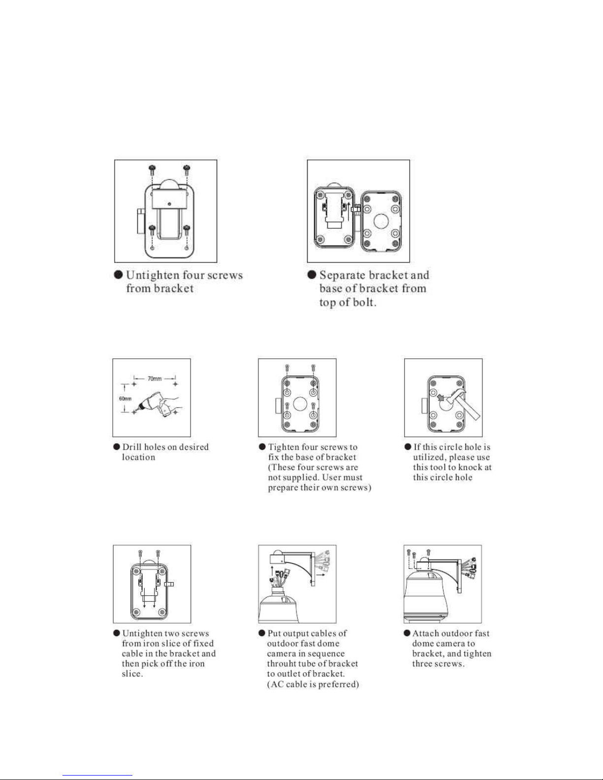
6. Installation
Step 2 Step 1 Separate bracket from base of bracket
Step 2 Fix base of bracket on the wall
Step 3 Attach camera to bracket
16

Step 4 Fast Dome Camera Setting
Step 5 Connect Jack
17

Step 6 Fix bracket and outdoor fast dome camera with base
18

7. System Configuration
P465 is suitable for a wide range of surveillance applications. The system can be single fast dome with
one keyboard or encompassing as 64 domes with comprehensive matrix switching, PC control and even
Digital Video Recording. Such flexibility means future expansion is easily facilitated.
7.1 Fast Dome and Keyboard
Single dome configuration: One fast dome camera connects to one PIH-800II or PIH-931D/932T.
Telemetry control is sent via twisted pair between Dome and Keyboard.
Video signal from the dome is sent to monitor or multiplexer or quad or switcher.
RS-485 Connection
1
st
pin TXDI+ of RS-485 jack at back of the keyboard connects to TXDI+ of RS-485 jack on fast dome.
2nd pin TXDI- of RS-485 jack at back of the keyboard connects to TXDI- of RS-485 jack on fast dome.
19

Multiple Domes means that more than one fast dome is linked in the system. Each dome connects to
next dome forming a serial linking. Each dome has an individual ID dip switch, which allows the keyboard
to identify each fast dome and make command. Sometimes it is more convenient to wire a telemetry
system in star configuration rather than daisy chain. To do this a PIH III data distributor is necessary. It
takes an output from a keyboard or a matrix and splits the single data line into 4 separate data lines. One
keyboard can control up to 64 cameras.
RS-485 Connection Between PIH-804III Data Distributor and fast dome
1
st
output TXDI1+ of PIH-804III connects to TXDI+ of 1st fast dome and TXDI1- of PIH-804III to TXDI- of
1st fast dome.
Linking 2nd Fast Dome
TXDO+ of 1st fast dome connects to TXDI+ of 2nd dome and TXDO- of 1st dome to TXDI- of 2nd dome.
RS-485 Connection Between PIH-804III Data Distributor and keyboard
1st pin TXDI+ on RS-485 IN jack of keyboard connects to TXDO+ on RS-485 OUT jack of PIH-804III
2nd pin TXDI- on RS-485 IN jack of keyboard connects to TXDO- on RS-485 OUT jack of PIH-804III.
20

7.2 Fast Dome, Matrix and Keyboard
Matrix system is designed to process multiple video system and video switching. Its central process unit
(CPU) can manage multiple video signals simultaneously and control other linking system, such as fast
dome or PIH-820III telemetry receiver.
All telemetry remote control and signal transmissions are through twisted pair. One matrix can manage
up to 64 fast domes.
Multiple keyboards can be used for matrix control. 1st keyboard is the master and the rests are slaves. Up
to 8 keyboards can be sued in one system. Each keyboard has a Dip Switch for ID setting. (Please refer
to keyboard’s manual for detail)
RS-485 Connection Between Matrix and Fast Dome
TXD+ of receiver jack on matrix connects to TXDI+ of 1
st
fast dome and TXD- of matrix to TXDI- of 1st fast
dome.
Linking 2nd Fast Dome
TXDO+ of 1st dome connects to TXDI+ of 2nd dome and TXDO- of 1st dome to TXDDI- of 2nd dome. 64
fast domes can be linked through the connection as shown.
RS-485 Connection Between Keyboards
TXDO+ of 1st keyboard RS-485 OUT connects to TXDI+ of 2nd keyboard RS-485 IN
TXDO- of 1st keyboard RS-485 OUT connects to TXDI- of 2nd keyboard RS-485 IN
21

RS-485 Connection Between Keyboard and Matrix
TXDI+ of 1
st
keyboard RS-485 IN connects to 1st pin TXD+ of matrix’s keyboard jack.
TXDI- of 1st keyboard RS-485 IN connects to 2nd pin TXD- of matrix’s keyboard jack.
7.3 Fast Dome with PC Control
PC telemetry remote controls fast dome with standard RS-485 data format (Baud Rate 9600bps). The PC
control port RS-232 is converted to RS-485 format by interface. User may use their own software
(protocol). In this system up to 64 fast domes can be linked.
22

RS-485 Connection Between Fast Dome and Conversion Interface
TXD+ of conversion interface RS-485 jack connects to TXDI+ of 1
st
fast dome and connect TXD- to
TXDILinking 2nd Fast Dome
TXDO+ of 1st dome RS-485 jack connects to TXDI+ of 2nd dome to TXDO- of 1st dome to TXDI- of 2nd
dome. 64 fast domes can link through the connection as shown.
7.4 Fast Dome, DVR and Keyboard
The DVR System is an advanced digital recording product, with long recording time and easy searching
features. Telemetry remote control is twisted pair for data transmission to the fast dome. Fast dome can
be controlled directly from the control panel of the DVR or from keyboard.
Each DVR (Digital Video Recorder) can manage 16 video signals and via RS-485 to daisy connection 16
sets of fast dome camera.
RS-485 Connection Between Fast Dome and DVR
TXD+ of DVR RS-485 jack connects to TXDI+ of 1
st
fast dome and TXD- of DVR to TXDI- of the 1st fast
dome.
Linking 2nd Fast Dome
TXDO+ of 1st dome RS-485 jack connects to TXDI+ of 2nd dome to TXDO- of 1st dome to TXDI- of 2nd
dome.
RJ-45 Connection Between DVRs
“Keyboard Out” of 1st DVR pass out RJ-45 jack connects to “Keyboard In” of 2nd DVR’s RJ-45 jack.
RJ-45 Connection Between DVR and Keyboard
“Keyboard In” of 1st DVR’s RJ-45 jack connects to RJ-45 jack of keyboard.
23

8. Software Installation
With the exception of the Macromedia Flash Player all the software that is necessary for the proper
display and use of the device is available on the included CD or from the website. For the following
installation procedures it is assumed that all installation media will be taken from the CD.
IP Installer
The IP Installer is used to locate and configure network cameras and video servers on the LAN. This
utility is useful for conveniently configuring the network settings of the NDC, or for finding a device once
the network settings have been modified.
To install the IP Installer, from the installation CD UI, select IP installer, then follow the on screen
instructions.
Component Installer
This will install all ActiveX components used by our devices for video display and device configuration.
Adobe Flash Player
Please visit the Macromedia Web site at http://www.adobe.com/downloads/ to download and install the
Flash Player.
24

9. Network Configuration
IP Installer is a utility that provides an easier, more efficient way to configure the IP address and network
settings of the camera. It even provides a convenient way to set the network settings for multiple devices
simultaneously using the batch setting function. Moreover, IP Installer can save the network settings for
all devices as a backup and restore them when necessary.
9.1 Preparation before IP Assignment
Always consult your network administrator before assigning an IP address to your server in order to
avoid using a previously assigned IP address.
Ensure the camera is powered on and correctly
connected to the network.
MAC Address: Each camera has a unique
Ethernet address (MAC address) shown on the
bottom of the camera as the serial number (S/N) with 12 digits (e.g. 000429-XXXXXX).
One final note, although the IP Installer is able to find and configure any camera on the LAN except
those that are behind a router, it is a good idea to set the host PC to the same subnet. In order to
connect to the Web-based user interface of the camera, the host PC must be in the same subnet.
For more information about subnets, please consult your network administrator.
9.2 Using IP Installer
Assigning IP address to Camera
Once IP Installer has been successfully installed on the computer, double click
the IP Installer icon on the desktop, or select it from Start > Programs > PiXORD
Corporation > IP Installer > IP Installer.
The IP Installer window is displayed below.
Click the menu bar Tool > Search Network Device to search the camera in the LAN.
25
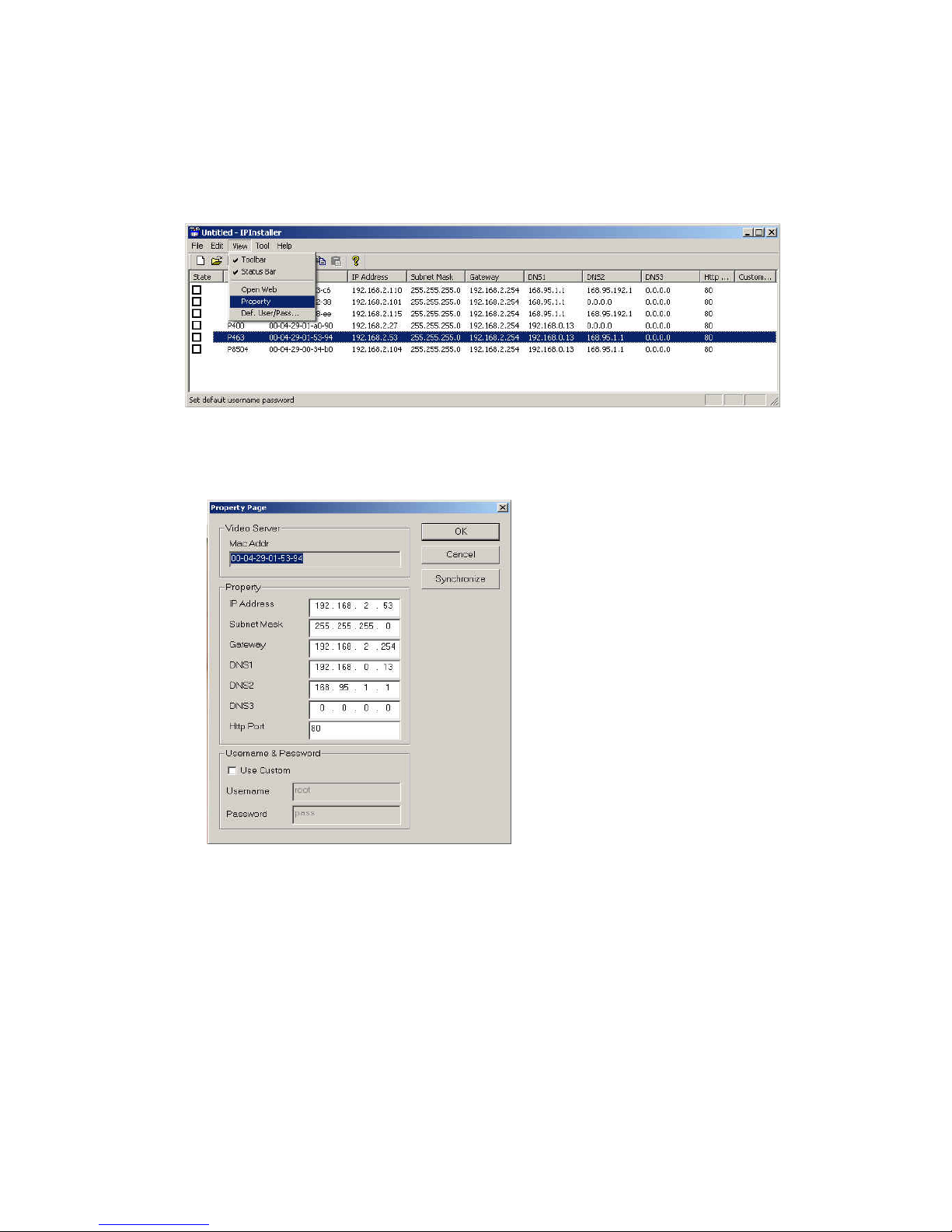
From the list, select the device with the MAC Address that corresponds to the device that is to be
configured. The MAC Address is identical to the unit’s S/N (Serial Number).
Double click the item to open the Property Page dialog box for the selected device or click the
menu bar View > Property.
After filling in the properties, click [Synchronize] button to complete the configuration settings in the
remote camera while saving configuration in the PC.
If click [OK] button, the configuration is only saved in the PC.
Open the Web-based UI of the Selected camera
To access the Web-based UI of the selected unit, run the View > Open Web on IP installer menu
bar.
If the device has been configured correctly, the default Web browser will open to the home page of
the selected device.
If you find your browser is opened and automatically connected to the camera Home Page, it
means you’ve assigned an IP Address to the unit successfully. Now you can close the IP Installer
and start using your camera.
26

Verify and Complete the Installation from Your Browser
Start your browser and enter the IP Address of your NDC in the Address field.
The camera can support Microsoft Internet ExplorerTM and NetscapeTM. But the voice feature can
only be run under Microsoft Internet ExplorerTM.
When browsing the Home Page at the first time with the Microsoft Internet ExplorerTM, you must
temporarily lower your security settings to perform a one-time-only installation of the ActiveX
component onto your workstation, as described below.
1. From the Tools menu, select [Internet Options]
2. Click the [Security] tab and then click [Custom Level] button to see your current security
settings.
3. Set the security level to Low and click [OK].
4. Type the URL or IP address of your camera into the Address field.
5. A dialog box will pop up asking if the ActiveX control should be installed. Click [Yes] to start
the installation.
6. Once the ActiveX installation is complete, return the security settings to their original value, as
noted above.
27

10. Usage of Web-based User Interface
Start your W eb browser and enter the IP Address of your Camera in the Address field. The Home page of
the camera is now displayed. The Web UI can present up to 4 video source indicating 4 video channels.
Each channel can be shown individually or in one of 4 split windows.
Full Screen
Maximizes to view the
selected channels into full
The status of the
video stream
1
34
2
10.1 Browse Live Video
Menu Language Selection
The online Web-based User Interface can allow the user to select 3
different languages: English, Traditional and Simplified Chinese.
Such display will not affect the original configuration for the
language, allowing multiple users to have different languages
concurrent views. In order to make the language change permanent,
settings must be modified through the Configuration page, and
saved once it is made.
Video stream
from camera
(Local video
source) External
video
28

10.2 Video Channel Selection
The Video Channel allows the users to choose viewing 1
channel at a time or 4 channels at the same time.
CH1 displays the video stream of the camera.
CH2~4 display the video stream of the IP Camera or Video
Server that connected the device via network.
Select “All” to display the local video stream (Channel 1)
as well as 3 external video sources (Channel 2 ~4).
Select 1~4 to display the video stream of single channel.
Select Actual to display the video stream at the actual
resolution
10.3 Pan / Tilt / Zoom Control
The PTZ control panel allows the users to pan, tilt and zoom the dome.
Speed: Click on the arrow button and select the speed of the Pan and Tilt movements. Values run
from 1 to 7. Being 1 the slowest and 7 the fastest.
Preset Point: Click on the arrow button and select the preset point from the pull-down list for quick
view.
Manual Pan/Tilt: Click on the 8-directions button to move the camera to that direction. Click on the
rectangle button to stop the movement.
180o button: The viewing will turn 180 degrees.
Zoom -: Click on this button for Zooming Out.
Zoom +: Click on this button for Zooming In.
Iris +: Opens the iris and brightens the picture.
Iris -: Opens the iris and reduces glare.
Focus +: The target will become nearer.
Focus -: The target will become farther.
Auto Iris: The lens will automatically adjust itself for
optimum iris.
Auto Focus: The lens will automatically adjust itself for optimum focus.
Auto Pan: Click on the arrow button to activate; click on the rectangle button to stop. When the
Auto Pan function is activated, the camera will auto touring the preset groups entered. Only the first
16 preset points of the camera can be set to auto pan mode and first 6 preset points are
corresponding with the 6 alarm.
29

To pan/tilt/zoom the external video sources CH2~CH4,
click on [CH2~4 PTZ Control] button to open a new
window. Select the channel in this window to display
the PTZ control panel for operation.
10.4 Digital Zoom Selection
The Digital Zoom enable user to select the digital size for the
channels.
Select [x1], [x4] or [x9] to enlarge the video.
Select [Draw Mode] and then use mouse to select an
area on the video for enlargement.
10.5 On/Off the Audio and Rotate the Video
The [Video Status] item allows the users to see the current settings of the selected channel. It also
includes the function for audio control, video rotation and record the video/audio for the selected channel.
Select the Channel
Click on the number tab, and status for the selected channel will be displayed. The settings can be setup
in Configuration page
On/Off the Audio
Select [On] or [Off] button to enable or disable the audio for
selected channel.
Rotate the Video
Click on [Rotation] button to temporary rotate the selected
video 90 degrees clockwise direction. This feature is to have
natural view for cameras that are hooked up on walls and/or
vertical positions.
30
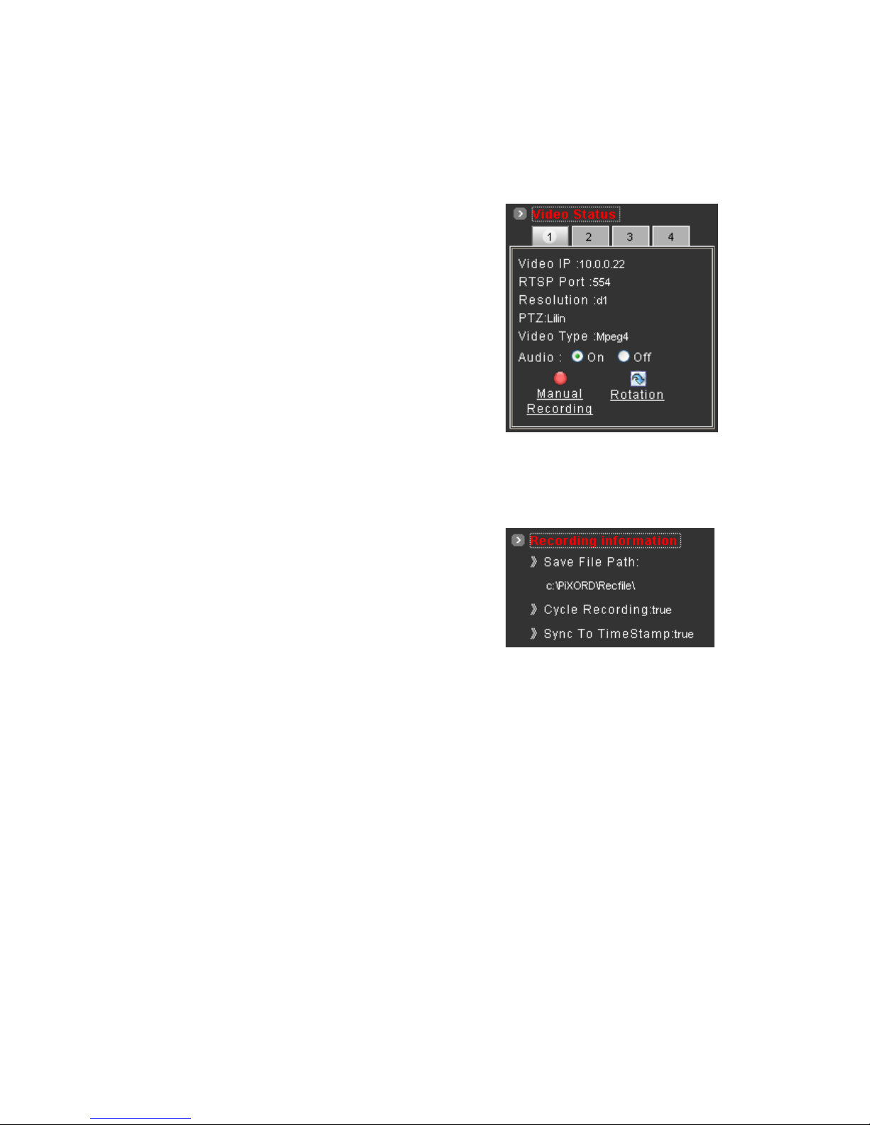
10.6 Video and Audio Recording
Before recording the selected channel, you can check the information of recorded file by clicking on
[Recording Information] item. The settings can be changed in Video Conference page.
To record the video and audio for each channel:
1. Click the channel number on the tab under [Video
Status].
2. Click on [Manual Recording] button, it will start
recording live video and audio of the selected
channel. A “REC” message will display on the
video.
3. The device can record multiple channels at the
same time. To record other channels, just repeat
step 1 and 2.
4. To stop recording, select the channel from the tab and then click [Manual Recording] button
again, the “REC” message will disappear and the recording is stopped.
By default, the recorded file will be saved in a folder named C:\PiXORD\Recfile\pppp\CHx\
♦ pppp : The model number of the device
♦ x : The number of the recorded channel
The default filename will be named under Locals_Rec-
yyyymmdd-hhmmss.avi
♦ yyyy : Current Year
♦ mm : Current Month
♦ dd : Current Date
♦ hh : Current Hour
♦ mm : Current Minute
♦ ss : Current second
The file will be saved as an AVI file, which can be play back with most media players.
The video is always recording with the actual direction. It will not be affected by the rotation of
viewing.
31

10.7 Video Conference
Click [Video Conference] to open the conference page.
Click this button backs to
the Home page
Click this button to open
the Configuration page
On/Off the audio of this
video stream
Rotate this video for
viewing
Record
Start recording
Stop
Stop recording
Setting
Configure the settings for
Recording
Camera
Select the remote
device
Control the Video in Location Window
PTZ Control
To control the dome camera, use the buttons on the PTZ Control panel to pan, tilt and zoom the camera.
Zoom -: Click on this button to Zooming Out.
Zoom +: Click on this button to Zooming In.
Focus +: The target will become nearer.
Focus-: The target will become farther.
32

Speed: Click on the UP/Down arrows and select the speed of the Pan and Tilt movements. Values
run from 1 to 7. Being 1 the slowest and 7 the fastest
Manual Pan/Tilt: Click on the 4-directions button to move the camera to that direction. Click on the
rectangle button to stop the movement.
Preset Point: Click on the number buttons to select a preset position for quick view.
Setting for Video Record
You can change the settings for recording by clicking on [Setting] button in Location window.
Reserve Space : Set the total file space
for the recording.
Max File Length : Set the file space that a
single file will be using.
Save File Path : Indicate which folder
should the file be saved to.
Location File Name : Input the name for
the file that recorded from the location
device.
Remote File Name : Input the name for
the file that recorded from the remote device.
Cycle Recording : This feature determine if the old space should be used or not for the recording.
Make a check mark in order to enable this function. If you enable this feature, old files will be
deleted
Sync to TimeStamp : This feature enables the file to be saved according to the time. When the
video file is displayed, the video will make a match between the frames and the time.
Apply: Click this button to save the changes made.
Return: Click this button returns to the live video of the location device.
Record/Stop: Click [Record] button to start recording. Click [Stop] button to stop recording.
Select the Remote Device
Select the camera from the pull-down list, the video of
the remote device will be displayed.
There are 4 cameras can be selected as the Remote
device. The first three are set up in the Configuration
page; the last one can be set up by clicking [Camera
Manual Setting] button
33

Manually Setup Additional Camera
This feature allows the user to temporary set an additional video source for the remote device.
Note: This camera will be removed after leaving or closing the Web page.
Click on [Camera Manual Setting] button on the Remote window, and configure the following settings:
IP address: Enter a valid IP address from an IP Camera or Video Server.
Http Port: Enter the port number used for the IP address for network connection.
Username/Password: Enter the respective Username and Password if applicable. If no user has
been set for the device, the default value should be root and pass respectively.
Video Channel: If the selected camera is connected to a Video Server, select the channel of the
Video Server.
Video Type: Select MJPEG or MPEG4.
The type must match the external source
provided.
Rotation: Rotate the video for view.
Rotation degrees run from 0 to 270
degrees.
♦ 0: 0 degree
♦ 1: 90 degrees
♦ 2: 180 degrees
♦ 3: 270 degrees
RTSP Port : Enter a RTSP Port used for
streaming in case the external source is
a MPEG4 device.
Name: Enter a name for the device.
PTZ Model: Enter a PTZ model.
Product Type: Select from MJPEG, MPEG4 Video Servers or IP Cameras. Please refer to the
original document of the device for a better description.
Test: Before submitting the information, click on this button to validate the video connection and the
live video will be displayed if the settings are correct.
Apply: Click this button to save the changes made.
Return: Click this button returns to the live video of the remote device.
34
11. Configuration of Web-Based User Interface
The Configurations of the camerras are presented as links in the margin of the Configuration Page.
Simply click the relevant link for the settings you want to configure.
11.1 Configuration Preview
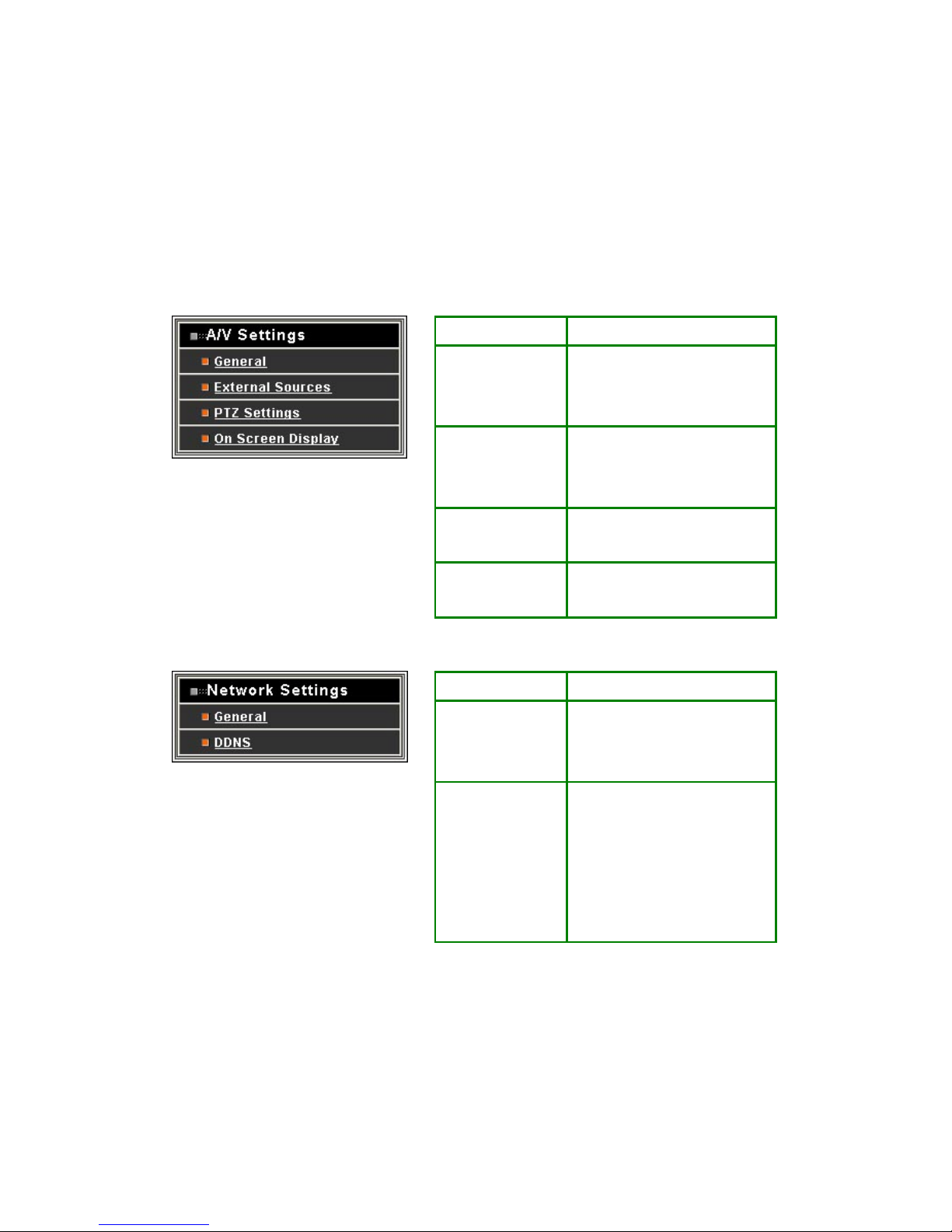
A/V Settings
Functions Description
General Set the parameters of video and
audio, and adjust the image of the
device.
External Sources Set the video source for channel 2
to 4, using digital inputs (IP
Address).
PTZ Settings To control the PTZ device and set
the preset points.
On Screen Display Set the text and location to display
on the video.
Network Settings
Functions Description
General Assign an IP Address and
configure the relevant network
parameters to the device.
DDNS The DDNS (Dynamic Domain
Name Service) is used to access
the camera with an easy
memorized name such as
http://demo.ddns.com instead of
http://192.168.0.200.
35

System
Functions Description
System Information Set various information about the
name of the device and the
language type, etc.
Time Configuration Set the Date and Time.
User Add and delete users and
passwords.
Firmware Upgrade Browse firmware location to
upgrading
Event
Functions Description
General Enable/disable the event trigger and
select the action when triggered.
Motion Area Set the area on video for motion
detection.
Email / FTP Input the Email and FTP address to
receive alert message or snapshot,
sent by event trigger.
Others
Functions Description
Live Returns to the Live Video display.
Reboot Close the Web browser and reboots
the device.
36

11.2 Configuration of A/V Setting
Basic A/V Settings
Audio: Enables and Disables the audio stream.
Resolution
There are 3 different resolutions to choose from:
♦ D1: 720x480 NTSC / 720x576 PAL (DVD Standard resolution)
♦ SIF: 352x240 NTSC / 352x288 PAL
♦ QSIF: 176x120 NTSC / 176x144 PAL
Frame Rate: The frame rate can be set between 5 to 30 FPS.
Encoder Format
♦ MPEG4 constant bitrates: Select MPEG4 and CBR.
♦ MPEG4 variable bitrates: Select MPEG4 and VBR
♦ Motion JPEG.
Bitrate
For Motion JPEG format, there are 4 variable bitrates between Low and High quality.
For MPEG4 format, there are 12 different constant bitrates to choose from 64Kbps to 4Mbps, and 4
variable bitrates between Low and High quality.
37

If you are planning on using the device on an Internet connection, it is recommended that you
select a constant bitrate that corresponds to your actual upload speed. It is also recommended that
you modify the frame rate and resolution as well, otherwise the video stream may become blocky
or otherwise distorted. The recommended settings for low-speed network connection are as
follows:
♦ 64Kbps: recommended settings are [QSIF, FPS<10]
♦ 128Kbps: recommended settings are [QSIF, FPS<15]
♦ 256Kbps: recommended settings are [SIF, FPS<10]
♦ 512Kbps: recommended settings are [SIF, FPS<15]
♦ 768Kbps: recommended settings are [Full D1, FPS<10]
♦ 1Mbps: recommended settings are [Full D1, FPS<15]
For higher frame rate use a variable bitrate instead. However, this is not recommended for
Internet use
♦ Average Quality is recommended if the VBR is selected.
♦ For Good Quality, full resolution (D1) and full frame rate (30/25 fps) it is recommended that
not more than 4 users connect simultaneously.
♦ For High Quality, full resolution (D1) and full frame rate (30/25 fps) it is recommended that
no more than 2 users connect simultaneously.
Auto adjust the frame rate under high traffic: After enable this option, the frame rate will be
automatic adjusted to
Note: Turn off audio will improve the video quality.
Apply: Click this button to save the changes made.
38

Advanced A/V Settings
Interlacing
There are 2 modes available: Interlaced or Progressive.
Interlaced mode is a storage mode. An interlaced video stream contains fields rather than frames, with
each field containing half of the lines of a frame.
A progressive video stream consists of only full frames.
Interlaced video streams can bring a lower bitrate but may cause lower quality.
TV Standard: The TV standard can be set among these 3 formats NTSC, PAL and SECAM.
Sequence Mode
There are 2 different modes available:
♦ I-frames only
♦ I-frames and P-frames
P-frames, or predictive frames, are predicted based on prior P or I-frames plus some additional data.
They have a much higher compression ratio than I-frames.
I-frame only mode has very little compression resulting in large file sizes.
I-frame and P-frame mode offers relatively good compression with medium file sizes. Although this
requires more work on the host PC to decode the video.
GOP Size: GOP stands for Group Of Pictures. It defines the number of frames from one I-frame to
the next. Since an I-frame uses very little compression, while P/B frames use much higher
compression, a larger GOP size results in smaller file sizes.
Peak Bitrate: This is used to set a maximum bitrate that can be achieved. This is useful for setting
bitrates between the values that are available from the Video Encoder bitrate list.
Apply: Click this button to save the changes made.
39

Image Adjustment
Contrast, Brightness, Hue and Saturation: The value can be adjusted from -100 to 100.
Rotation: Rotation degrees run from 0 to 270 degrees for a permanent digital position.
♦ 0: 0 degree
♦ 1: 90 degrees
♦ 2: 180 degrees
♦ 3: 270 degrees
Load Default: Click this button to set the image adjustments back to factory default.
Save: Click this button to save the changes made.
40

11.3 Setting External Sources
Video Select: Select the channel this external source will be displayed.
IP Address: Enter a valid IP address from an IP Camera or Video Server.
Http Port: Enter the port number used for the IP address for network connection.
Video Type: Select MJPEG or MPEG4. The type must match the external source provided.
Rotation: Rotation degrees run from 0 to 270 degrees for a permanent digital position.
♦ 0: 0 degree
♦ 1: 90 degrees
♦ 2: 180 degrees
♦ 3: 270 degrees
Video Channel: If the external source is a camera connected to a Video Server, select the channel
of the Video Server.
Username/Password: Enter the respective Username and Password if applicable. If no user has
been set for the device, the default value should be root and pass respectively.
RTSP Port: Enter a RTSP Port used for streaming in case the external source is a MPEG4 device.
PTZ Model: Choose a PTZ model.
Name: Enter a name for the device.
Product Type: Select from MJPEG or MPEG4 Video Servers or IP Cameras. Please refer to the
original document of the device for a better description.
Test: Before submitting the information, click on this button to validate the video connection and the
live video will be displayed if the settings are correct.
Apply: Click on this button to save the changes made.
41

11.4 PTZ Settings
Managing Preset Points
Managing the Preset Points for
quick view and auto pan.
Setting ID for NDC
Select an ID number to match the ID
address set by the dome camera.
Advanced Function Setup for Camera
This pair of buttons is for call out the OSD Setup Menu, and set
up more functions.
Setting Day / Night Mode
Changing Lens Speed
Switching the lens speed between
default setting and manual setting.
Setting the ID for Network Dome Camera
To select an ID number to match the ID address set by the NDC ID switch:
1. Click on the arrow button beside Camera ID and select the number from the pull-down list.
2. Click on [Apply] button to confirm the selection.
42

Operating the Dome Camera
To control the dome camera for viewing, follow the description shown on below:
Pan / Tilt the Dome Camera
To control the pan and tilt movement of the dome camera
simply click on the buttons:
To pan or tilt, just click on the 8-directions buttons for the
desired direction.
To adjust the speed of the movement, just click on the
arrow button beside “Speed” and select the desired
speed from the pull-down list. The higher the number
selected, the faster the speed.
Zoom Lens Control
To zoom in: Click [+] button, the viewing angle becomes
narrower and target will become enlarged on the screen.
To zoom out: Click [-] button, the viewing angle becomes
wider and target will become smaller on the screen.
180o Revolve
The viewing angle will turn 180
o
.
Iris Control
The purpose of iris control is to adjust brightness on target. It
can be set as Auto Iris or Manual Iris.
Iris open: Click [+] button, to open the iris and brighten
the picture.
Iris close: Click [-] button, to open the iris and reduce
glare.
Auto iris: Click the arrow button beside “Auto Iris”, the
will automatically adjust itself for optimum iris.
lens
Focus Control
The focus function can be set as Auto Focus or Manual
Focus.
Manual focus near: Click [+] button, the target will
e farther.
Manual focus far: Click [-] button, the target will become
er.
Auto focus: Click the arrow button beside “Auto Focus”,
will automatically adjust itself for optimum focus.
becom
near
the lens
43

Preset Point Setting
There are 128 individual preset points. Each preset stores the exact position of the camera and
automatic pan, tilt, zoom, focus and iris setting. Once the data is set, the preset can be recalled for
viewing, or the presets can be set for auto pan.
Note: Only the first 16 preset points of the device can be set to auto pan mode and first 6 preset points
are corresponding with the 6 alarm inputs.
Selecting Preset Point
Click on the arrow button and select the desired number
from the pull-down list.
Setting Preset Dwell Time
Click on the arrow button and select the desired value from
the pull-down list.
Setting Preset Speed
Click on the arrow button and select the desired value from
the pull-down list.
Save / Remove Preset Data
Click on [Save] button will save the current data as a
preset point.
Click on [Remove] button will erase all 128 preset points.
Selecting Preset Group for Auto Pan
Select the groups by clicking on the check boxes, then click
[Submit] button to save the changes made.
Activate / Stop Auto Pan
Activate: Click the arrow button.
Stop: Click the rectangle button.
Setting Preset Point
Select a preset point. (If this point has been set previously, the following procedure will change the
previous settings after saving)
Move the camera to the desired view position. (Refer to the previous page)
Adjust the zoom, focus and iris of lens. When set up preset point, using manual focus will provide
both clarity and stability of image. (Refer to the previous page)
Set preset Dwell time. The dwell time means the time user wants to view on certain preset point
under Auto Pan. The Dwell time can be set between 1 ~ 255 seconds.
44

Set preset speed. The speed the dome travels to that preset point can be adjusted between 10 to
250 seconds.
The presets Group 1 ~ 4 (First 16 preset points) can be entered a name for identify. Just fill the text
string into the Position Name field.
Save the preset point. Once the above steps have been completed, the information must be stored
or it will not be memorized by the system.
Note: For the first 16 presets on each dome, the above steps must be repeated. For presets 17 ~
128 there is a default speed and dwell setting so steps 4 and 5 are not required.
Setting Preset Group for Auto Pan
The purpose of setting preset group allows the management of the 16 preset points before Auto
Scanning. The first 16 preset points are separated into 4 groups. Preset group must be set for the auto
pan reference.
Group 1 includes: 1st, 2nd, 3rd and 4th preset points.
Group 2 includes: 5th, 6th, 7th and 8th preset points.
Group 3 includes: 9th, 10th, 11th and 12th preset points.
Group 4 includes: 13th, 14th, 15th and 16th preset points.
To select the groups, click on the check boxes of the groups, then click [Submit] button to save the
changes.
Activate / Stop Auto Pan
When the Auto Pan function is activated, the dome camera will auto touring the preset groups entered.
To activate: Click the arrow button.
To stop: Click the rectangle button.
Deleting Preset Points
Sometimes it is necessary to delete the stored preset points. Just click the [Remove] button
.
Note: All the preset points can be cleared by clicking on [Remove] button
45

11.5 Setting Day / Night Mode
There are 3 modes can be selected to set the IR Cut Filter for different environment. Click IR filter Swap
to switch the modes.
ICR ON (ICR IN): IR Cut Filter is ON and always produces constant color image.
ICR OFF (ICR OUT): IR Cut Filter is OFF and always produce monochrome image.
ICR AUTO
♦ P463/ P463T: When light drops below 3 Lux, switch from color to monochrome
automatically.
♦ P463DW : When light level is over 30 Lux, IR Cut Filter switches IN automatically to
produce color image. When light drops below 10 Lux, IR Cut Filter switches OUT
automatically to produce monochrome image. Under monochrome mode, sensitivity is
increased to 0.01 Lux and can be used with IR illuminators.
11.6 Changing the Lens Speed between Default and Manual Setting
Click on Lens Speed to switch the Lens speed between default speed and the manually setup speed.
46

11.7 On Screen Display
On Screen Display: Select Enable/Disable for displaying the text over the video.
OSD Text: Fill in the text string to display. The valid characters are a – z, A – Z, 0 – 9, !, @, #, $, %,
&, *, ( and ).
Note: The maximum display block area is 12X4 characters. String length longer than 12 will feed
to next line, and total 4 lines are available. More than 4 lines will strip off.
OSD Coordinate X / Y: To change the location of text, just fill in the X and Y coordinate.
Display Font Grey Level: Change the color of the displayed font.
Apply: Click this button to save the changes made.
47

11.8 Configuration of Network Setting
General Settings
MAC Address: Display MAC address information for this device. It is read only information.
IP Address: IP address of the device.
Subnet Mask: Subnet mask of your LAN. Note that the IP Address above and Gateway IP Address
below should be in the same subnet.
Device Name: Enter a name for the device.
Gateway Address: The gateway IP address for the network segment to which the device is
connected. This device traffic to Internet should go through Gateway, if not setting this, only
Intranet (LAN) can be accessed.
DNS Address 1, 2 and 3 : The DNS server IP address used for resolving domain names to IP
addresses. DNS Address 2 and 3 are optional.
IP Setting Mode
Static IP - Manually assigned IP address.
DHCP – If there is a DHCP server installed on your LAN, you can select DHCP to automatically
assign an IP address for the device and obtain default gateway, and DNS server.
HTTP Port: Specify the HTTP web server listen port for client (browser) connection. Default uses
port 80 (HTTP standard port), valid range from 0 ~ 65535.
48

Note: Before changing the listen port, user must add a port directive “:” in browser URL in order to get
correct connection. (i.e. http://<IP>:<Port> , e.g.
http://192.168.0.200:8000) to access the device with IP
192.168.0.200 and port with 8000).
These features enable user to use the device behind NAT or IP Sharing devices which could access up
to 65536 NDC with one IP Address.
RTSP Port: The port on which the device will receive RTSP (streaming video) requests.
Apply: Click this button to save the changes made.
Dynamic DNS Settings
The DDNS (Dynamic Domain Name Service) is used when users want to access the camera with an
easy memorized name such as http://demo.ddns.pixord.com instead of http://61.220.235.172. This
service could be useful when the camera is located behind Dial-up ADSL or IP sharing devices, which
does not have fix IP address and it’s impossible to reach the camera from Internet.
When the camera enables the DDNS service, it will “register” to the DDNS server with its information,
such as server name to access, router virtual port number and updated frequency, etc.
Then camera automatically “update” to the DDNS server by a fix frequency, so even the IP is changed by
ISP, the DDNS server sti ll could get and update internal da tabase. Then, once users a ccess fro m Internet
with its register name, e.g. if registering with server name “demo” to DDNS server “ddns.pixord.com”, the
camera could be accessed by
http://demo.ddns.pixord.com.
49

Dynamic DNS Settings 1
Dynamic DNS Settings: Select [Enable] if you wish to activate the DDNS service.
Device Name: Specify server name. This name setting also used by the DDNS service to
recognize each server.
E.g. if configure name as “user” to DDNS address “ddns.pixord.com”, then this NDC can be
accessed by URL http://user.ddns.pixord.com after register to the DDNS server.
DDNS Server Address: Specify address of the DDNS server.
DDNS Connection Port: Specify the DDNS server listen port, and the default is “80”
Router Incoming Port: Specify your router listen port for the DDNS server to redirect. The router
may configure the different port for incoming (Internet request) and outgoing (Intranet request), e.g.
it may configure to redirect Internet HTTP (port 80) request to Intranet port 8000, then, in this case,
we must configure the “Router Incoming Port” to 80, and inside the camera Network settings
should set HTTP port with 8000.
Update Time: Specify the camera updated frequency in seconds, and the default is 600 (10
minutes), this is interval that camera will automatically send an updated packet to the DDNS server.
DDNS Message: Return messages from remote DDNS server, and some hints may help to
diagnostic the reason if register fails.
♦ DDNS addr. CGI fail:
It means that camera can’t communicate with Internet world. Make sure your Network
Configuration has correct subnet mask and default gateway, and DNS1 setting is correct and
reachable.
♦ Already registered:
Another user had registered this name; please change your register name by changing
“Device Name”.
♦ Apply: Click this button to save the changes made
50

Dynamic Settings 2
Dynamic DNS Settings: Select [Enable] if you wish to activate the DDNS service through DynDns.
DDNS Host Name: Specify server name that you have registered in http://www.dyndns.org
E.g. if the registered name is “user” to DynDns, then this NDC can be accessed by URL
http://user.dyndns.org
Account ID: Enter the username provided by DynDns.
Password: Enter the respective password for the account.
DDNS Message: Return messages from remote DynDns server.
Apply: Click this button to save the changes made.
Example:
To setup a camera (IP address 192.168.0.200) behind a dialup ADSL router, and wish to access by name
http://demo.ddns.com. And, the procedure is as below:
Configure the ADSL router with PPPoE enable; LAN IP, 192.168.0.254; and subnet mask, 255.255.255.0.
♦ Assign the ADSL router’s virtual server with service port 80 to server IP 192.168.0.200
♦ In Network Settings > General page, configure the camera network configuration with IP
address 192.168.0.200; subnet 255.255.255.0; DNS1 with valid DNS address such as
168.95.192.1 or 168.95.1.1; gateway IP address with 192.168.0.254 (router’s IP); HTTP
port with port 80.
♦ Configure the Device Name.
♦ Configure Dynamic DNS Settings with Enabled; DDNS Server Address with “ddns.com”;
DDNS Connection Port with port 80; Router Incoming Port with 80; and Update Time with
600 (10 minutes). Finally, clicks [Apply] button.
♦ If DDNS message success, then enter URL http://demo.ddns.com on browser.
Consequentially, it will show the camera’s home page.
51
11.9 Configuration of System
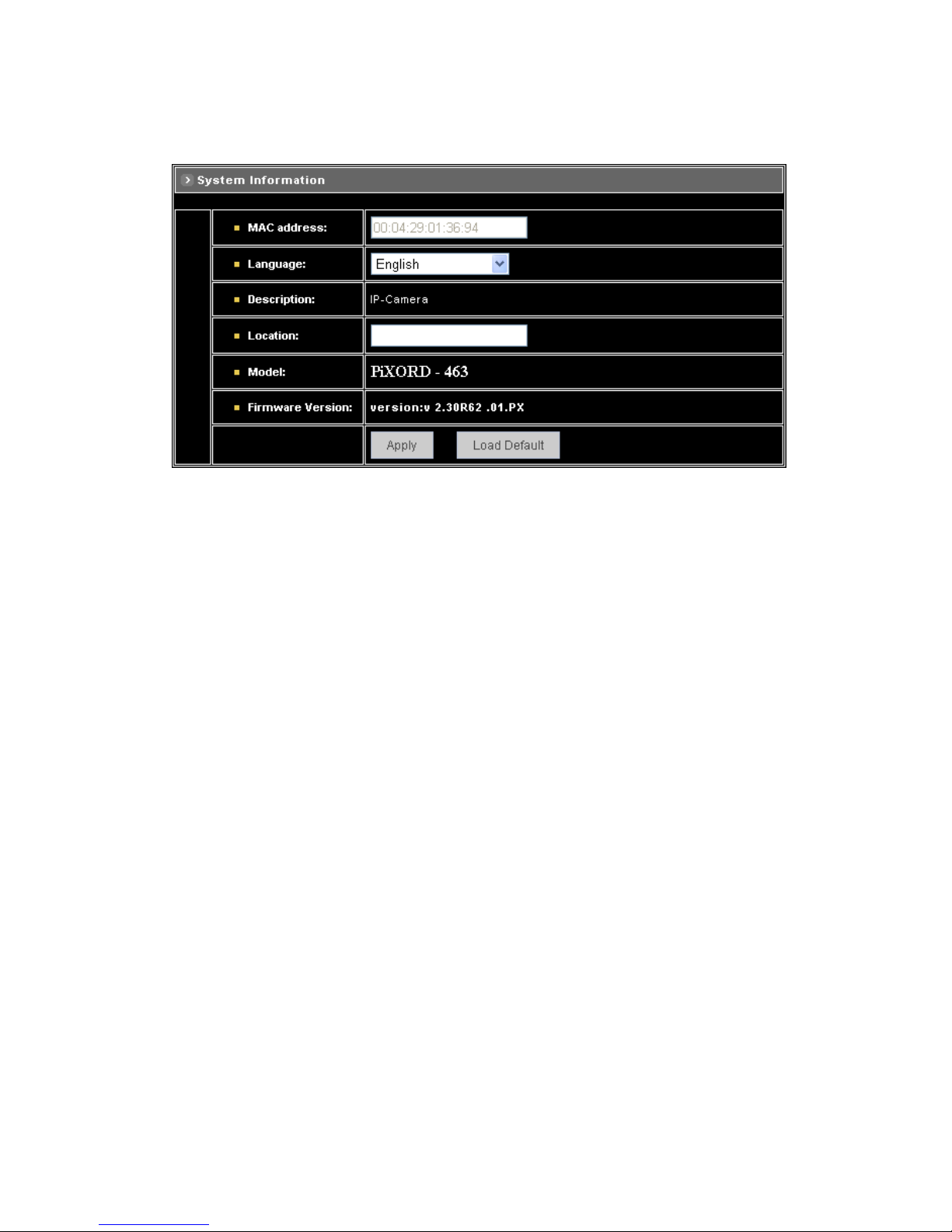
System Information
MAC Address: Display MAC address information for this device. It’s read only.
Language: Alternative language option. User may change the language of web contents for
different application.
Description: Useful as an administrative identifier. Does not affect the operation of the device.
Location: Useful for identifying the position of the device. Does not affect the operation of the
device.
Model: Displays the model number for the device.
Firmware Version: Display firmware version information.
Load Default: Click this button to restore the settings back to factory default.
Apply: Click this button to save the changes made.
52

Time Configuration
Time Mode
♦ Synchronize with NTP server: Synchronize the current time with a NTP server over
Internet.
♦ Set Manually: Manually set the time.
Click on [Synchronize with computer time] button to set the date/time of the camera as your PC’s, or
Set the date and time by clicking on the arrow button beside each field and select the value from the
pull-down list.
Click on [Apply] button to save the configuration.
Time Zone: Click on the arrow button and select the appropriate time zone from the pull-down list.
NTP Server 1, 2 and 3: Assign the NTP servers to use for time synchronization. A list of NTP
servers can be found at: http://www.eecis.udel.edu/~mills/ntp/clock2a.html
Apply: Click this button to save the changes made.
53

User Settings
Add User
T o add a user , enter the user name and password in the respective fields. Select [Group] and [Permission]
of each channel, and then click on [Add User] button.
The user in Administrator group has all permission to operate the device.
The user in General group can be configured to have limited permission to operate the device.
Delete User
To remove a user, select the user from the list, and then click on [Delete User] button.
Note:
Totally 10 users can be added.
The first added user must have administrative right (Administrator group), and must be the last one
to be removed.
The username and password cannot contain the “:”, “,” characters. And the length must be
between 1 and 7 characters.
User name cannot be modified.
54

11.10 Firmware Upgrade
T o upgrade firmware, first browse the folder where you have placed the newest firmware. After finding the
path then click on “Update” to upgrade the device.
55

11.11 Configuration of Event
General
Trigger
System provides “GPIN” and “Motion Detection” for event detection.
GPIN & GPIO Input Status: They are auto detected and display the status.
Motion Detection: Make a checkmark on this option to start detect the motion area. See next
segment to set the motion area.
Action
Make a checkmark on either FTP Image, Mail Image, or on all of them, to determine what action should
be taken when the event is triggered.
FTP Image: Send the image to the configured FTP site when event is triggered. Click on the link to
set the FTP server.
Mail Image: Send the image to the configured mail address when event is triggered. Click on the
link to set the Email addresses.
Alert Message Status: They are auto detected to display the status, the signal can be used with the
recording application software on PC.
Apply: Click this button to save the changes made.
56
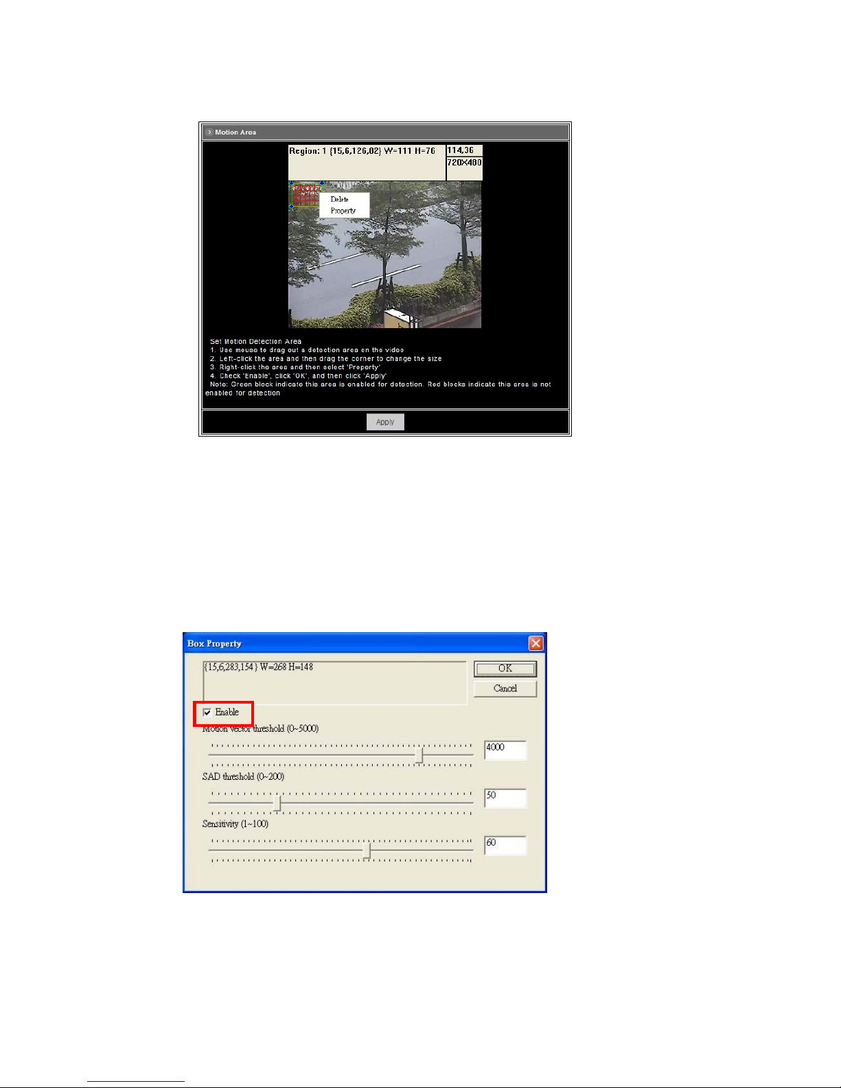
Set Motion Area
The “Motion Detection” checkbox (Configuration>Event>General>Trigger) must be enabled when use
this function.
Use mouse to drag out a detection area on the video.
Left-click the area and drag the corner to change the size.
Right-click the area and select “Property”.
Check “Enable”, click “OK” and click “Apply”.
Note: Green blocks indicate this area is enabled for detection. Red blocks indicate this area is not
enabled for detection.
57
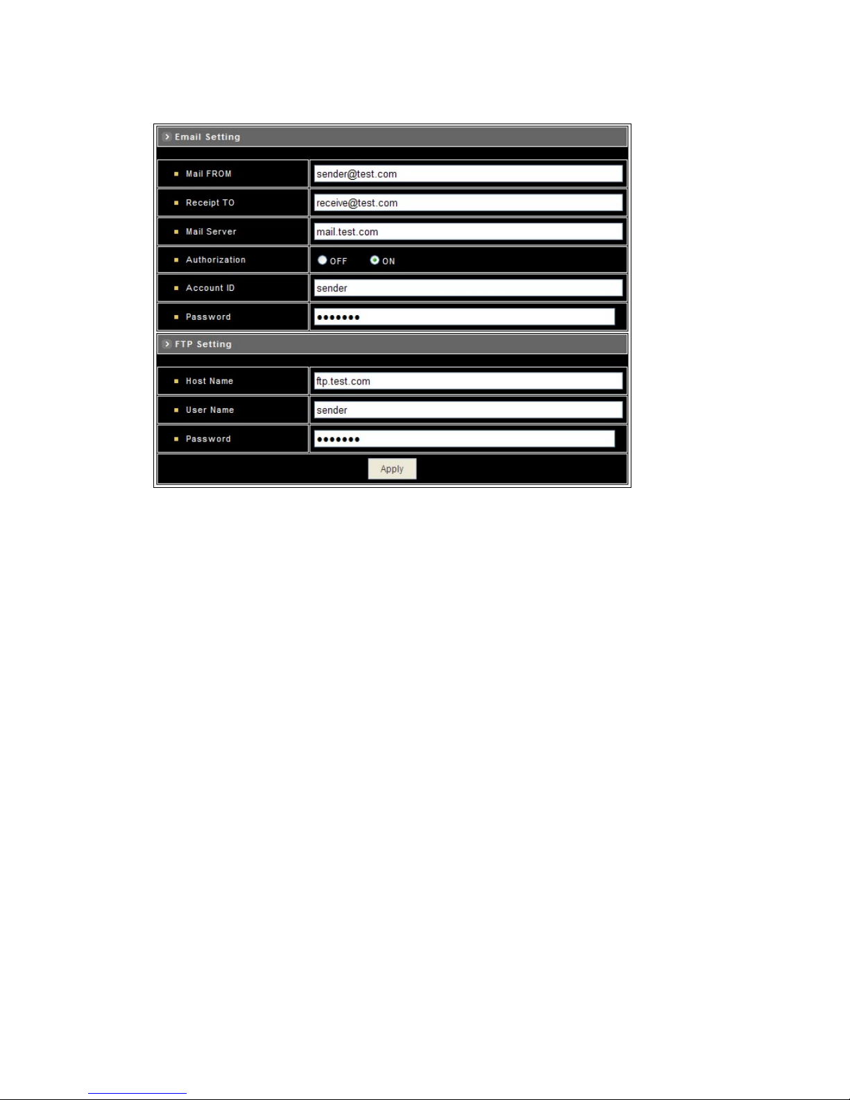
Set Email and FTP
E-mail Setting
The “Mail Image” checkbox (Configuration>Event>General>Action) must be enabled when use this
function.
Mail From: Enter the mail address of the mail sender.
Receipt To: Enter the mail address of the mail receiver.
Mail Server: Enter the mail server name or IP address.
Authorization: Disable or enable the security for mail authorization.
Account ID and Password: Enter the user name and password for the mail sender.
FTP Setting
The “FTP Image” checkbox (Configuration>Event>General>Action) must be enabled when use this
function.
Host Name: Enter the IP address of the FTP server.
User Name and Password: Enter the user name and password for the FTP server.
Apply: Click this button to save the changes made.
58
12. Operation
12.1 Initial Power Up Inspection
After the power is first applied to a dome it will perform a self-test procedure. This calibrates and checks
the basic functions of the dome, control is not possible during this self-test period. Once the camera has
stopped moving, it will then be ready to control. If preset positions and tours have been programmed into
a dome and the power is turned off, the dome will enter the Auto Scan mode once the power is turned on
again (after self-test period). The dome will remain in Auto Scan until an operator cancels it.
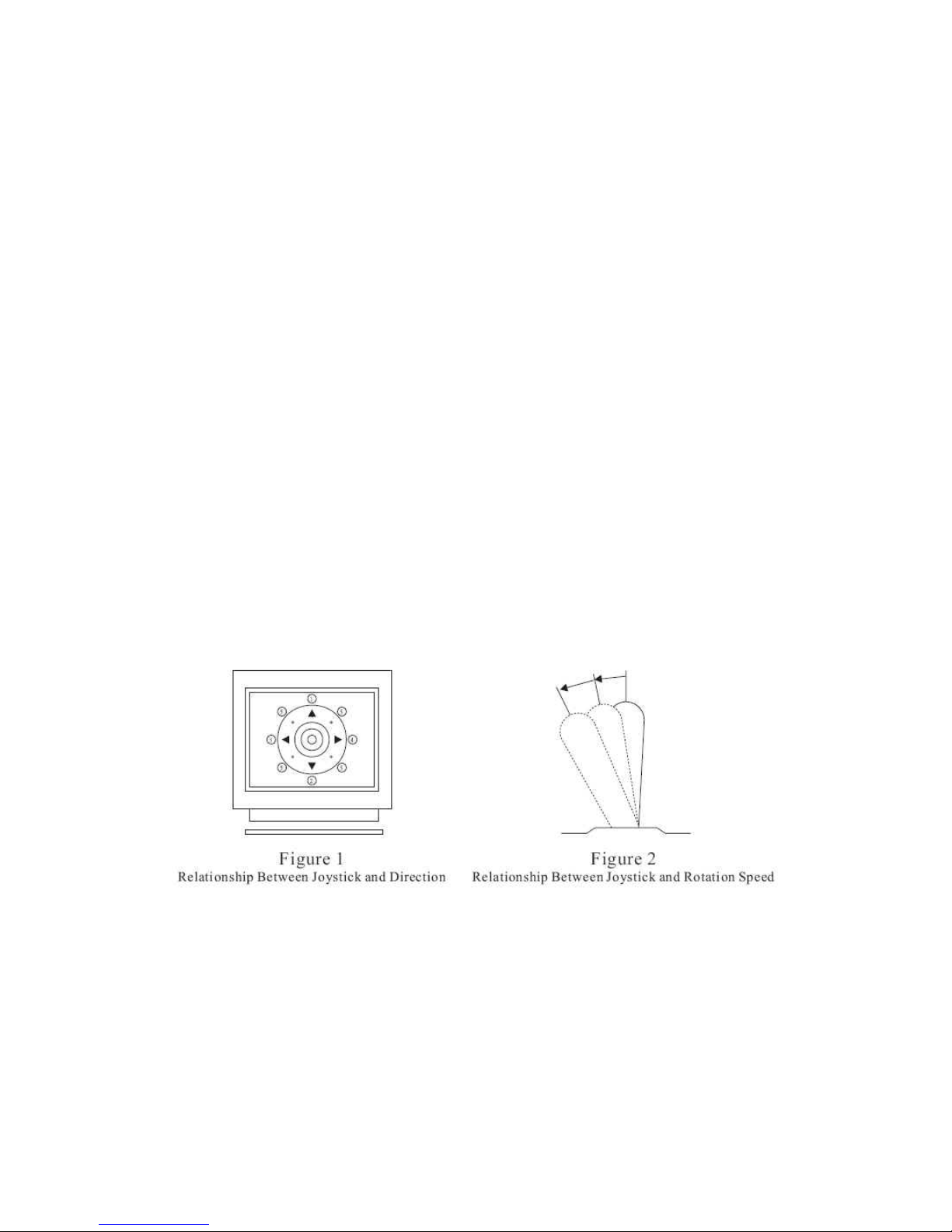
12.2 Manual Operation (Pan/Tilt Control)
To control the pan and tilt movement of the dome simply use the joystick on the keyboard; to pan the
camera left push the joystick to the left, to tilt down pull the joystick down (towards you). To move the
dome faster push the joystick further in that direction, the joystick is proportional to the speed of the dome;
a small movement will move the dome slower.
UP: Push the joystick forward, the camera tilt up
DOWN: Push the joystick down (towards you), the camera tilt down
LEFT: Push the joystick left, the camera pan left
RIGHT: Push the joystick right, the camera pan right
DIAGONAL: Push the joystick diagonally, the camera moves to that direction (direction 5 on figure 1)
59

12.3 Fast Dome Selection
To call out a dome controlling or setting
To Select 1st Fast Dome
Push
followed by key
To select 64
th
Fast Dome
Push key
then followed by
key
Note: When matrix system is used, select monitor before camera selection. Please refer to matrix system
user manual.
12.4 Zoom Lens Control
To Zoom In
Push
key. The
viewing angle becomes narrower and
target will become enlarged on the
screen. Zooming will stop when the key
is released.
To Zoom Out
Push
key. The viewing angle becomes wider and target will become
smaller on the screen. Zooming will stop when the key is released.
12.5 Focus Control
The focus function on Fast Dome can be set as Auto Focus or Manual Focus.
Manual focus far key
Push
key. The
target will become farther. Focusing will
stop when the key is released.
Manual focus near
Push key.
The target will become nearer. Focusing will stop when the key is released.
Auto Focus
Push key. The lens will automatically adjust itself for optimum focus.
60
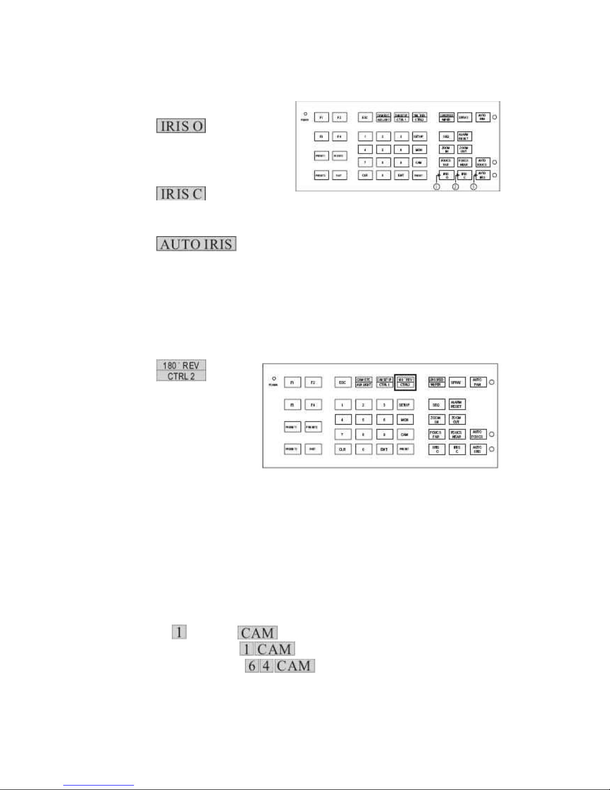
12.6 Iris Control
The purpose of this iris control is to adjust brightness on target. It can be set as Auto Iris or Manual Iris.
Iris Open
Push
key, to open the iris
and brighten the picture. Iris will stop
when the key is released.
Iris Close
Push key, to open the iris
and reduce glare. Iris will stop when the key is released.
Auto Iris
Push key, to select the Auto Iris mode.
12.7 Horizontal 180° Instant Flip
Sometimes it is hard to use the joystick to control the camera tracking the target directly under the
camera. The instant flip key can rotate the camera 180° instantly. This allows the camera continue to
track the target passing directly under the camera.
Two ways to operate 180° instant flip:
Push
key on
keyboard to flip the camera 180°
horizontally.
Push joystick down to bring the
camera down to the end,
release the joystick and quickly
push joystick down twice to flip the camera 180° horizontally.
12.8 Preset Position Setting
Each dome can have 128 individual preset positions. Each preset stores the exact position of the camera
and automatic pan, tilt, zoom, focus and iris setting. Once the data is set, the preset can be recalled for
viewing or the presets can be set for auto pan.
Note: Only the first 16 preset positions of the fast dome can be set to auto pan mode and first 6 preset
positions are corresponding with 6 alarm inputs.
Selecting Fast Dome
Push key
followed by key, confirming that first camera is selected.
EX. To select 1st fast dome: keys.
To select 64th fast dome: keys.
61

Selecting Preset Position
Push key
followed by key, confirming that first preset position selected.
EX. To select the 1
st
preset position: keys.
To select the 128th preset position: keys.
Joystick Control
Move the joystick to bring the camera to the desired view position.
Adjusting Lens
ZOOM IN/OUT, FOCUS NEAR/FAR/AUTO and IRIS O/C/AUTO keys.
When set up preset point,
using manual focus will
provide both clarity and
stability of image.
Setting Preset Speed
The speed the dome travels to that preset position can be adjusted between 1° to 255° per second
(factory default is 255°/sec)
To set speed as 10°/sec: Push
key
followed by
key, two beeps will be
heard confirming that speed
is set.
Note: Push
key again
to confirm speed entered.
Setting Preset Dwell Time
The dwell time means the time user wants to view on certain preset position under Auto Pan. The
Preset Dwell Time can be set between 0~255 seconds. (Factory default is 0 second)
Note: If the dwell time is set to 0 second then that position will be omitted from the Auto Scan Tour.
To set dwell time to 5 seconds: Push followed by key.
EX. To set dwell time to 5 seconds: keys.
To set dwell time to 10 seconds: keys.
62

Storing Preset Data
Once the above steps have been completed, the information must be stored or it will not be
memorized by the system. Push
followed by key, two beeps will be heard confirming
that data is stored.
Note: For the first 16 presets on each dome, the above steps must be repeated. For presets
17~128 there is a default speed and dwell setting so steps 5 and 6 are not required.
12.9 Recalling Preset Positions
Once the required preset positions have been stored in a dome, they may be quickly recalled, returning
the dome to exact position.
To recall the 1
st
Preset Position: Push followed by key.
The dome will move to that position in speed of 360°/sec
EX. To recall 1st preset position: keys
To recall 128th preset position: keys
12.10 Setting Preset Group
The purpose of setting preset group allows the management of the 16 preset positions before Auto
Scanning. The first 16 preset positions of each dome are separated into 4 groups. Preset group must be
set for the auto pan reference.
Group 1 includes: 1, 2, 3 and 4 preset positions
Group 2 includes: 5, 6, 7 and 8 preset positions
Group 3 includes: 9, 10, 11 and 12 preset positions
Group 4 includes: 13, 14, 15 and 16 preset positions
To set up group 1: push key
followed by key
EX. To set Group 1:
To set Group 1, 2:
To set Group 2, 3, 4:
To set Group 1, 2, 3, 4
63

12.11 Changing Preset Data
In order to change any preset position from the one stored, the dome must first be sent to that preset
position. To change the 4th preset position of the Dome number 3, perform the following steps:
1. Push
to select Dome 3
2. Push to go to 4th preset position
3. Move joystick to bring camera to the desired view position
4. Adjusting lens
5. Setting preset speed
6. Setting dwell time
7. Stored Data
(Please refer to preset position setting for steps 3~7)
12.12 Activating Auto Pan
When the Auto Pan function is activated, the fast dome will auto touring the preset groups entered.
To activate Auto Pan
Push
key,
confirming the activation of auto
pan. (Auto Pan Led will be lit)
To stop Auto Pan
Push
key again, confirming the stop
of auto pan. (Auto Pan Led will be off)
Note: If Auto Pan is activated, no other commands can be sent to that dome but other dome can
still be selected and operate manually.
To select (call out) another dome while it is under Auto Pan Mode
Simply push the numeric key followed by the
key.
Push
followed by key, confirming the 2nd camera is selected.
12.13 Deleting Preset Data
Sometimes it is necessary to delete the stored data. All the data can be cleared from a dome by pressing
key
followed by the key.
(All 128 preset data will be erased)
Push followed
by key.
64

12.14 Alarm Management
The 6 alarm inputs of each fast dome are corresponding with the first 6 preset positions. When an alarm
signal is triggered, the dome will go to the relevant position at 360°/sec. Make sure the first 6 preset
positions are set to desired alarm areas. Alarm input can be set to NC (normally close) or NO (normally
open) depends on alarm detector.
Relationship Between Alarm Inputs and First 6 Presets
Alarm Input 1 will send the dome to Preset Position 1
Alarm Input 2 will send the dome to Preset Position 2
Alarm Input 3 will send the dome to Preset Position 3
Alarm Input 4 will send the dome to Preset Position 4
Alarm Input 5 will send the dome to Preset Position 5
Alarm Input 6 will send the dome to Preset Position 6
Alarm Response Mode
The fast dome alarm response can be set to Lock or Release mode
Lock: Dome remains at last alarmed preset point
Release: Dome moves between alarmed points then reverts to prior status such as auto pan.
Lock Mode: When an alarm is triggered, the dome will go to the relevant position at 360°/sec and
the keyboard will audio alert user until it is canceled manually. To manually cancel the alarm trigger ,
push
key. If more than one alarm is triggered, the fast dome will
lock on the last alarm triggered position.
Release Mode:
1. Under Auto Pan Mode
When an alarm is triggered under Auto Pan, fast dome goes to the relevant position at 360°
/sec. The alarm is canceled automatically and gets back to Auto Pan mode after alarm time. If
more than one alarm is triggered, the fast dome moves between alarmed points every 5
seconds and gets back to Auto Pan mode.
2. Not Under Auto Pan Mode
When an alarm is triggered not under Auto Pan, the fast dome goes to the relevant position at
360°/sec. The alarm is canceled automatically after alarm time. If more than one alarm is
triggered, the fast dome moves between alarmed points every 5 seconds.
3. The audio alert for alarm trigger will remain on until it is manually canceled by pushing the
key.
65

12.15 Alarm Output
Each fast dome has 1 alarm output. A dip switch can program the alarm output for NO (normally open) or
NC (normally close), that can activate the linked devices.
When alarm response mode is set to LOCK Mode:
When the alarm is triggered, NC contact to Common will be open and NO contact to common will
be close. Alarm output will be back to the condition before alarm, 10 seconds after the last alarm is
triggered.
When alarm response mode is set to RELEASE Mode:
When the alarm is triggered, NC contact to Common will be open and NO contact to common will
be close. Alarm output will be back to the condition before alarm, 60 seconds after the last alarm is
triggered.
66

13. Setup Menu Tree
67

68

14. Fast Dome Camera Function Setup
P465 (built-in 35X optical zoom lens with Hi-Resolution and Day & Night function) provide on-screen
display (OSD) setup menu, all functions can be selected and set via OSD setup menu.
14.1 Setup Menu Display
Press key on the keyboard to recall setup menu.
Press
key to exit setup menu or push joystick down to select <EXIT> and then press
key to exit setup menu.
14.2 Language Selection
Press key into setup menu.
Push joystick down to select <LANGUAGE> and then push joystick left or right to make selection:
Press
key to exit setup menu or push joystick down to select <EXIT> and then press
key to exit setup menu.
69
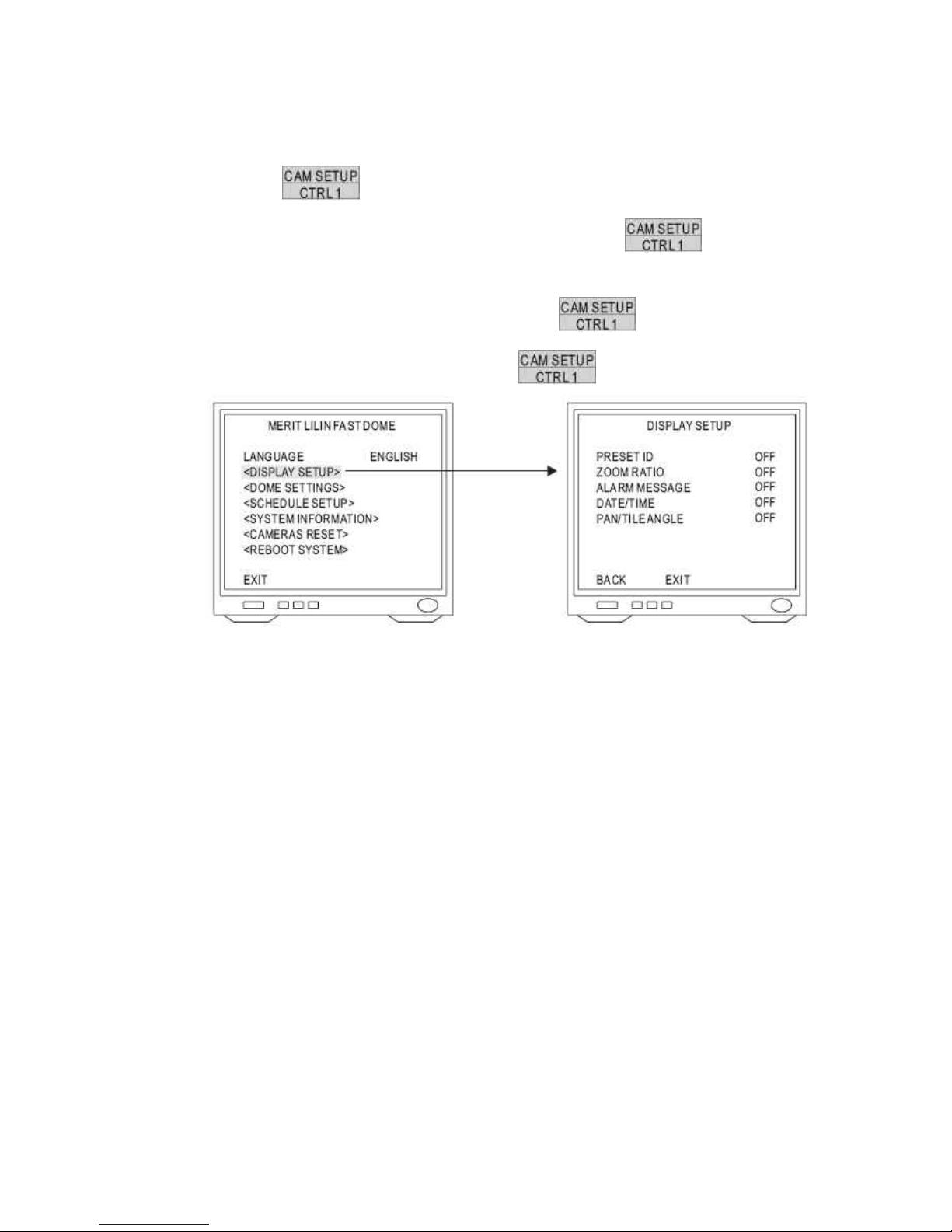
14.3 Display Setup
1. Display Setup Menu
Press key into Setup Menu.
Push joystick down to select <DISPLAY SETUP> and then press key to
display setup menu.
Push joystick down to select <BACK> and then press key to go back or push
joystick down to select <EXIT> and then press key to exit setup menu.
2. Preset ID setting
Push joystick down to select <PRESET ID> and then push joystick left or right to make
selection:
OFF: No Preset ID on the monitor screen
1~255 sec: Display elapsed time. Preset ID will have been displayed on the monitor screen
until elapsed time stops, when Preset ID is recalled.
3. Zoom Ratio Setting
Push joystick down to select <ZOOM RATIO> and then push joystick left or right to make
selection:
OFF: No Zoom Ratio on the monitor screen
1~255 sec: Display elapsed time. Zoom Ratio will have been displayed on the monitor
screen until elapsed time stops, when Zoom Ratio is operated.
4. Alarm Message Setting
Push joystick down to select <ALARM MESSAGE> and then push joystick left or right to
make selection:
OFF: No Alarm message on the monitor screen.
1~255 sec: Display elapsed time. Alarm Message will have been displayed on the monitor
screen until elapsed time stops, when Alarm Input is triggered.
70

5. Date and Time Setting
Push joystick down to select <DATE/TIME> and then push joystick left or right to make
selection:
OFF: No Date/Time on the monitor screen
ON: Display Date/Time on the monitor screen. When selection is open and then press
key, date/time will be set.
Time Adjustment:
Push joystick down to select <TIME> and then press
key to setup time.
Push joystick left or right to adjust time, and then press key to next item of time.
Date Adjustment:
Push joystick down to select <DATE> and then press
key to setup date.
Push joystick left or right to adjust date and then press key to next item of date.
Date Format Setting:
Push joystick down to select <DATE FORMAT> and then push joystick left or right to adjust format
of date.
71

6. Pan/Tilt Angle Setting
Push joystick down to select <PAN/TILT ANGLE> and then push joystick left or right to select
pan/tilt setup:
OFF: No Pan/Tilt Angle on the monitor screen
ON: Pan/Tilt Angle on the monitor screen.
72

14.4 Dome Setting
Press key into setup menu.
Push joystick down to select <DOME SETTINGS> and then press key into dome
setting menu.
14.5 Camera Setting
1. Display the Camera Setting Menu
After getting in dome setting menu, push joystick down to select <CAMERA> and then press
key into camera setting menu.
1. Auto Focus Setting
Push joystick down to select <AUTO FOCUS> and then push joystick left or right to
select auto focus mode.
73

Auto: Keep performing auto focus function for object.
Interval: Fix interval time (5 sec) performing auto focus function for object.
Zoom Trigger: Auto focus function will be performed, when only this condition that
camera zoom ratio is changed.
2. Zoom Minimum Setting
Push joystick down to select <ZOOM MIN> and then push joystick left or right to adjust
zoom minimum setting. Minimum range is X01~X10
3. Zoom Maximum Setting
Push joystick down to select <ZOOM MAX> and then push joystick left or right to adjust
zoom maximum setting. Maximum range is X18~X35.
4. Zoom Speed Setting
Push joystick down to select <ZOOM SPEED> and then push joystick left or right to
adjust zoom speed setting. Zoom speed range is 00~07
5. Focus Speed Setting
Push joystick down to select <FOCUS SPEED> and then push joystick left or right to
adjust focus speed setting.
6. Auto Iris Setting
Push joystick down to select <AUTO IRIS LEVEL> and then push joystick left or right to
adjust auto iris level. Auto iris level is 00~16.
2. Advance Setting
After getting in camera setting menu, push joystick down to select <ADVANCED SETTING>
and then press
key into advanced setting.
1. Exposure Mode Setting
Push joystick down to select <EXPOSURE MODE> and then push joystick left or right
to setup auto mode or manual mode
74

Auto Exposure: will automate to select shutter speed by brightness variation to exhibit
image effect of high brightness area
Press
key into Auto Exposure
Setting and then push joystick left or right to
made selection.
Manual Exposure: Can set a fixed shutter speed with iris to exhibit image effect.
Press key into Manual Exposure Setting and then push joystick left or
right to made selection
2. Backlight Compensation Setting
Push joystick down to select <BACKLIGHT>
and then push left or right to select “ON” or “OFF”.
Note: When “ON” is selected, the brightness gain is automatically controlled for
backlight compensation in response to the light intensity detection window.
3. Flicker Less
Push joystick down to select <FLICKER LESS> and then push joystick left or right to
select ”ON” or “OFF”.
Note: When “ON” is selected, shutter speed will be fixed at 1/100(120) sec to prevent
image flash phenomenon under fluorescent light.
75
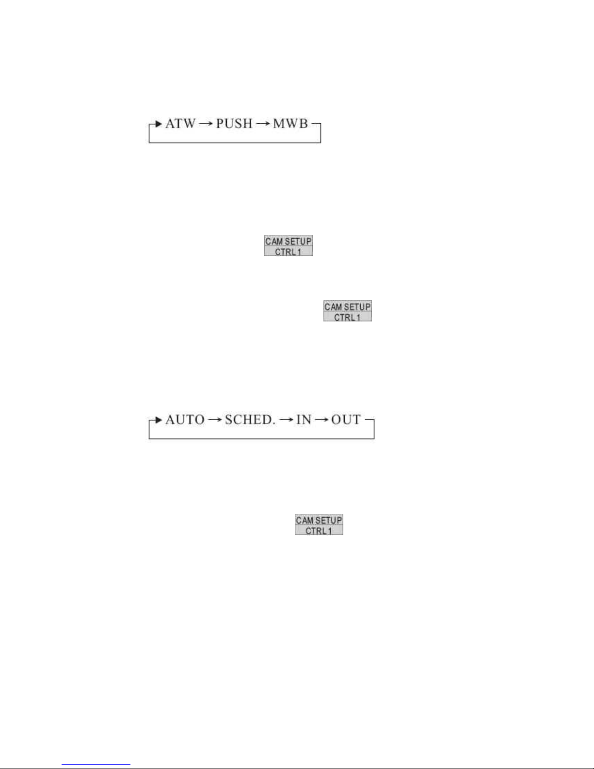
4. White Balance Setting
Push joystick down to select <WHITE BALANCE> and then push joystick left or right to
select white balance mode.
ATW: Auto Tracing White Balance, suitable for 2500~9500K color temperature
environment.
PUSH: Push mode, suitable for 2300~10000K color temperature environment.
MWB: Manual White Balance, suitable for 2500~9500K color temperature
environment.
Select <MWB> and press
key into MWB adjustment image and then
push joystick left to adjust white balance to higher color temperature or push joystick
right to adjust white balance to lower color temperature.
Confirm color temperature and then press key to recode datum in the
memory.
5. IR Cut Filter Setting
Push joystick down to select <IR CUT REMOVE> and then push joystick left or right to
select mode
Auto: When light level is over 30 lux, IR Cut Filter switches IN automatically to produce color
image. When light drops below 10 lux, IR Cut Filter switches OUT automatically to produce
monochrome image. Under monochrome mode, sensitivity is increased to 0.01 lux and can be
used with IR illuminators.
When selection is <AUTO>, press
key into IR Cut Setting menu.
Push joystick down to select <IR SENSITIVITY> and then push joystick left or right to
select sensitivity steps (01~15).
Note: When IR sensitivity setting value is low and lightness is darker, IR CUT Filter will
be performed.
76

SCHED: IR CUT FILTER switches automatically between Day mode and Night mode by
schedule of time setting.
When selection is <SCHED.> press key into ICR SCHEDULE Setting
menu.
Push joystick down to select <DAY-> NIGHT> and then press key into
time setting. Push joystick left or right to select time of DAY->NIGHT. Then press
key again to next item.
Push joystick down to delete <NIGHT->DAY> and then press
key into
time setting. Push joystick left or right to select time of NIGHT->DAY. The press
key again to next item.
IN: IR Cut Filter is ON and always produce constant color image.
OUT: IR Cut Filter is OFF and always produce constant monochrome image.
77
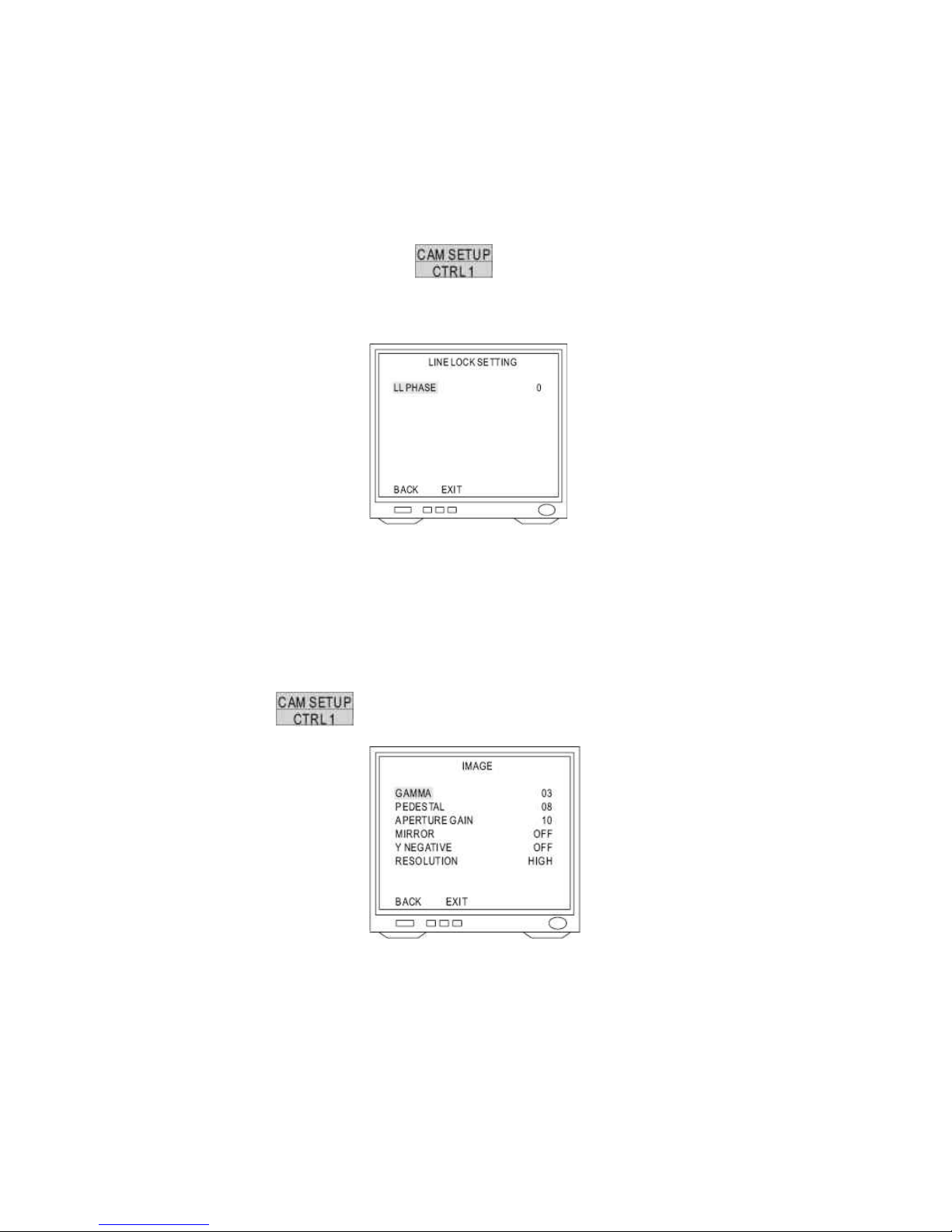
6. Synchronization Mode Setting
Push joystick down to select <SYNC MODE> and then push joystick left or right to
select mode.
INT: Use synchronization signal of internal camera.
LL: Synchronize synchronization signal of camera and AC signal of external power.
Select <LL> and press
key into LL setup and then push joystick left or
right to adjust LL phase. (0~100, each step is 3.5°, phase adjustment is 0°~350°)
7. Auto Gain Control Setting
Push joystick down to select <AGC LIMIT> and then push joystick left or right to make
selection. Auto Gain Control range is 0db~3db.
3. Image Setting
After getting in advanced setting menu, push joystick down to select <IMAGE> and then
press
key into image setting menu.
1. Gamma Setting
Push joystick down select <GAMMA> and then push joystick left or right to make
selection (00~07)
2. Pedestal Setting
Push joystick down to select <PEDESTAL> and then push joystick left or right to make
selection (00~15)
78

3. Aperture Gain Setting
Push joystick down to select <APERTURE GAIN> and then push joystick left or right to
make selection (00~15).
4. Mirror Setting
Push joystick down to select <MIRROR> and then push joystick left or right to make
selection (OFF or ON)
Note: Image will be Left/Right reverse.
5. Y Negative Setting
Push joystick down to select <Y NEGATIVE> and then push joystick left or right to
make selection (OFF or ON)
Note: This function inverse the Y signal.
6. Resolution Setting
Push joystick down to select <RESOLUTION> and then push joystick left or right to
make selection (HIGH or NORMAL)
High: 520 TV lines
Normal: 480 TV lines
14.6 Pan/Tilt Setting Menu
1. Display the Pan/Tilt Setting Menu
After getting in the dome setting menu, push joystick down to select <PAN/TILT> and then
press
key into pan/tilt setting menu.
2. Home Position Setting
Push joystick down to select <HOME POSITION> and then push joystick left or right to select
home position.
OFF: NO action
1~128: Home position is preset position from fast dome.
Note: When keyboard control isn’t used, “Return Mode” is set for “Home” and “Return Time”
is over, “Return Mode” function will be started.
79

3. Self Return Time Setting
Push joystick down to select <SELF RETURN TIME> and then push joystick left or right to
select return time.
OFF: NO action
1~9: Delay time of return time setting is 1~90 min.
Note: When keyboard control isn’t used, “Return Time” is also over, “Return Mode” function
will be started.
4. Self Return Mode Setting
Push joystick down to select <SELF RETURN MODE> and then push joystick left or right to
select return mode.
OFF: NO action
Home: Perform return home position mode
Auto: Perform auto scan mode
SEQ: Perform preset group mode
TOUR 1: Perform tour 1 list mode
TOUR 2: Perform tour 2 list mode
PATROL: Perform memory patrol mode
Note: When keyboard control isn’t used and “Return Time” is also over, “Return Mode”
function will be started.
5. Auto Mode Setting
Push joystick down to select <AUTO MODE> and then push joystick left or right to select
mode.
OFF: NO action
Auto: Perform auto scan mode
SEQ: Perform preset group mode
TOUR 1: Perform tour 1 list mode
TOUR 2: Perform tour 2 list mode
PATROL: Perform memory patrol mode
Note: Press
key on the keyboard to perform Auto mode function
80

6. Auto Scan Mode Setting
Push joystick down to select <AUTO MODE> or <SELF RETURN MODE> and then push
joystick left or right to select <AUTO> then press
key into auto scan mode
setting.
1. Position of Auto Pan Setting
Push joystick down to select <EDIT POSITION> and then press key
into setting menu.
Push joystick left, right, up or down to select start position and then press ,
, , , , to adjust zoom, focus, iris then
press key to confirm.
Push joystick left, or right to select end position and then press key to
confirm.
2. Dwell Time Setting
Push joystick down to select <DWELL TIME> and then push joystick left or right to select
dwell time (1~255 sec)
3. Scan Speed Setting
Push joystick down to select <SCAN SPEED> and then push joystick left or right to
select scan speed (1~40 deg/sec)
81

7. Patrol Mode Setting
Push joystick down to select <AUTO MODE> or <SELF RETURN MODE> and then push
joystick left or right to select <PATROL> then press
key into patrol mode
setting.
1. Patrol Learn Setting
Push joystick down to select <LEARN> and then press key into setting
menu.
Control joystick or press control key of lens to start patrol learn mode (Count down time
from 100%~1%)
Press key to end patrol learn mode.
Note: Patrol mode can record all control action of keyboard and when Auto Pan
Function is select, camera will perform patrol mode before setting.
2. Clear Memory of Patrol
Push joystick down to select <CLEAR> and then press
key to clear all
memory of patrol.
82
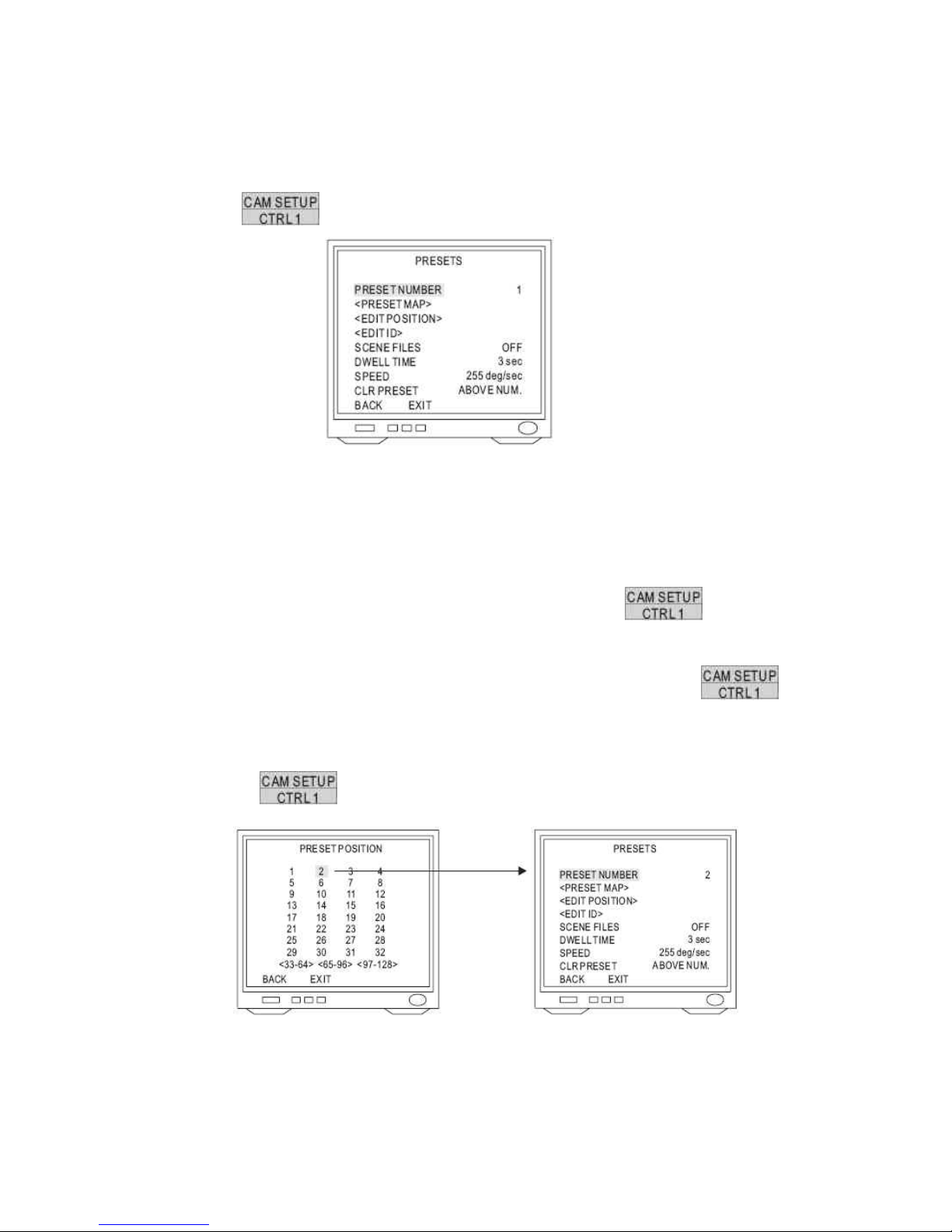
14.7 Preset Function Setting Menu
1. Display the Preset Setting Menu
After getting in dome setting menu, push joystick down to select <PRESETS> and then press
key into presets setting menu.
2. Select Preset Numbers
Select number by PRESET NUMBER: Push joystick down to select <PRESET NUMBER>
then push joystick left or right to select preset number (1~128)
Select number by PRESET MAP:
1. Push joystick down to select <PRESET MAP> and then press
key into
preset map.
2. Push joystick left, right, up or down to select preset number and then press
key into preset setting menu.
3. If need to select preset numbers 33~64, push joystick down to <33~64> then press
key into preset number 33~64.
83

3. Edit Position Setting
Push joystick down to select <EDIT POSITION> then press key into preset
position setting.
Push joystick left, right, up or down to start position and then press , ,
, , , to adjust zoom, focus, iris then press
key to confirm.
4. Edit ID Setting
Push joystick down to select <EDIT ID> and then press key into preset ID
setup.
1. New Preset ID Editing
Push joystick down to select character and press key to confirm. The
character selected will be showed in edit area. If you need space, push joystick down to
select <SPACE> and press key to confirm.
Press or to switch to next character list.
Repeat all steps to complete preset ID.
2. Copy preset ID to Another Preset
Push joystick down to select <EDIT AREA> and push joystick left or right to select first
copy of characters.
Push joystick down to <COPY> and press key to confirm. At this time first
character of preset ID will be copied to first character position of another preset ID and
press key to do next copy.
84

Push joystick down to <OK> and press key to exit. Select another preset
on the preset menu and get into preset ID setting. Then push joystick down to “EDIT
AREA” and press key for copy. At this time edit area will show preset ID
that was copied.
3. Modify Preset ID
Push joystick down to select <EDIT AREA> on the preset ID setting and push joystick
right to select modifiable characters.
Push joystick down to select new characters and press key to chose.
4. Cancel Preset ID
Push joystick down to <CANCEL> then press key to cancel preset ID.
5. Preset ID Position Setting
Push joystick down to “POSI” and press key to get in.
Push joystick to move preset ID to needful position of frame then push key
to confirm.
6. Return Preset Setting
Push joystick down to “OK” and then press key to back to preset menu.
5. Scene File of Preset Setting
Push joystick down to select <SCENE FILES> then push joystick left or right to select scene
file mode (OFF or ON)
Select <ON> press key into scene file of preset menu.
Exposure Mode: AUTO / MANUAL
White Balance: ATW / PUSH / MWB
Note: When scene file of preset is “ON”, it will be
part of preset parameters.
85

6. Dwell Time Setting
Push joystick down to select <DWELL TIME> and then push joystick left or right to select
needful dwell time (1~255 sec)
Note: Only preset No.1~16 can set dwell time, because group of auto pan can only edit preset
No 1~16. Other preset numbers can’t set dwell time.
7. Speed Setting
Push joystick down to select <SPEED> then push joystick left or right to select speed of preset
(1~255 deg/sec)
Note: Only preset No 1~16 can set speed, because group of auto pan can only edit preset No
1~16. Other preset numbers can’t set speed.
8. Cancel Preset
Push joystick down to select <CLR PRESET> then push joystick left or right to select <ABOVE
NUM> or <ALL>. Then press
key to confirm.
ABOVE NUM.: Only cancel parameter of allotted preset
ALL: Cancel parameters of all presets (1~128)
14.8 Tour Function Setting Menu
1. Display the Tour Setting Menu
After getting in dome setting menu, push joystick down to select <TOURS> then press
key into tours setting menu.
2. Tour Number Selection
Push joystick down to select <NUMBER>
then push joystick left or right to select Tour 1
or 2.
3. Edit Tour
Push joystick down to select <EDIT TOUR> then press key into edit tour
setting.
Push joystick up or down to select number. When joystick down to last line, push joystick down
again to get in next table of page. Each tour table can edit 32 presets.
Push joystick left or right to select preset (1~128)
Press key to confirm then push jo ystick to select <BACK> then press
key again to back to tours setting or push joystick to select <EXIT> then press
86

key to exit.
4. Cancel Tour
Push joystick down to select <CLEAR ABOVE NUMBER> then press key to
cancel tour.
5. Dwell Time Setting
Push joystick down to select <DWELL TIME> then push joystick left or right to select dwell
time of tour (1~255 sec)
Note: When Self Return Mode or Auto Mode is Tour, dwell time of Auto Pan will be dwell time
setting of tour.
6. Speed Setting
Push joystick down to select <SPEED> then push joystick left or right to select preset speed
(1!255 deg/sec)
Note: When Self Return Mode or Auto Mode is T our, speed of Auto Pan will be speed setting of
tour.
87

14.9 Privacy Zones Setting Menu
1. Display the Privacy Zones Setting Menu
After getting in dome setting menu, push joystick down to select <PRIVACY ZONES> and
press
key into privacy zones setting menu.
2. Privacy Zones Number Setting
Push joystick down to select <NUMBER> then push joystick left or right to select number (1~8)
Note: If privacy zone is “OFF”, privacy zones setting won’t be edited.
3. Edit Privacy Zones
Push joystick down to select <EDIT ZONE> then press
key into Edit Zone
mode. Also middle of monitor will display privacy zone mask area.
Push joystick left or right to adjust privacy mask position.
Adjust optical zoom lens and auto focus then press key to confirm and get into
privacy zone mask area for editing.
Press key then push joystick left, right, up or down to extend privacy zone mask
area.
Press
key then push joystick left, right, up or down to reduce privacy zone mask
area.
After completing setting, press
key to confirm and back to privacy zones setting
menu.
Note: Optical lens can just adjust 1X to 12X in edit zone mode.
88
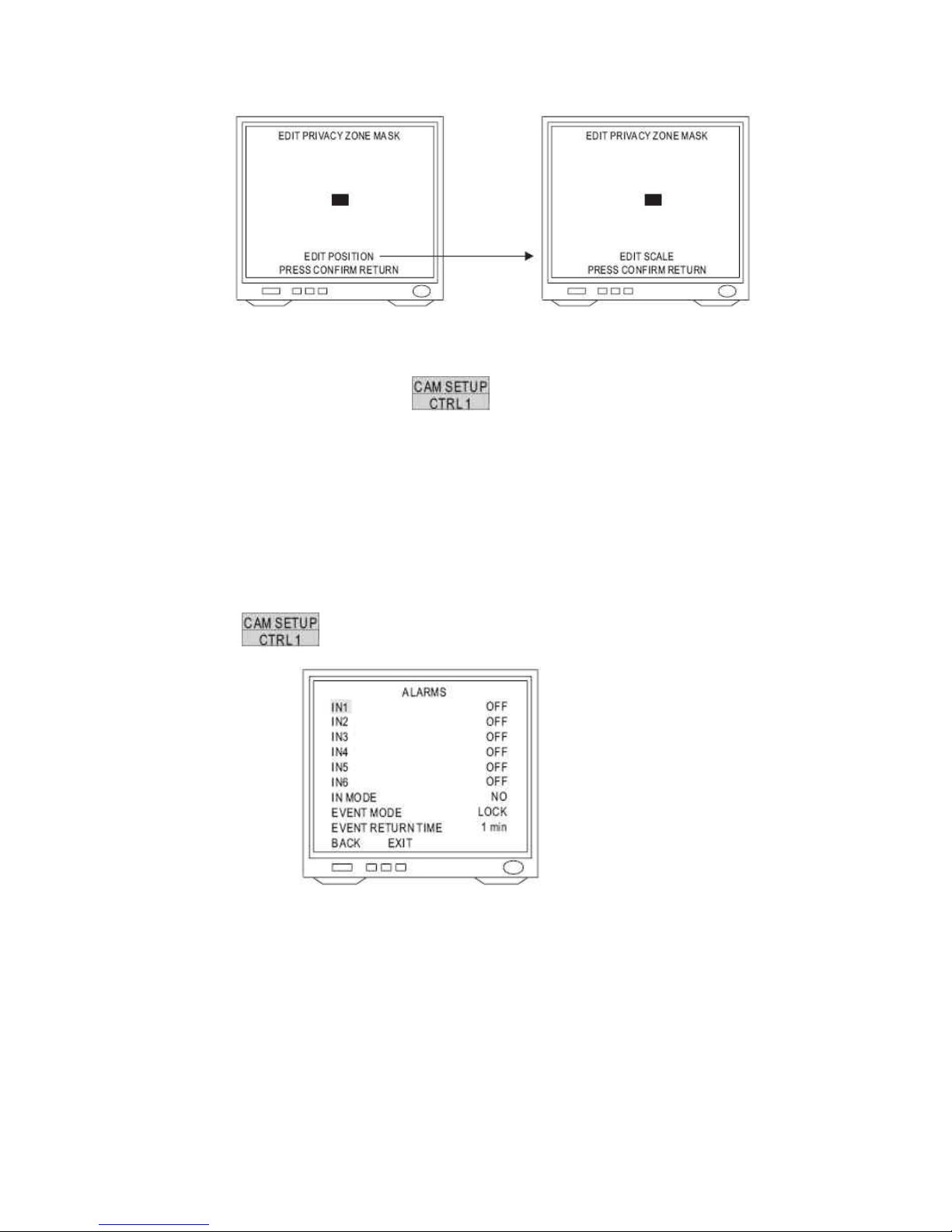
4. Cancel Privacy Zone Mask
Push joystick down to select <CLEAR> then push joystick left or right to select <ABOVE
NUM.> or <ALL>. Then press
key to confirm.
ABOVE NUM>: Only cancel parameter of allotted privacy zone.
ALL: Cancel parameters of all privacy zone (1~8)
14.10 Alarm Setting Menu
1. Display the Alarm Setting Menu
After getting in dome setting menu, push joystick down to select <ALARMS> then press
key into alarms setting.
2. Input of Alarm Setting
Push joystick down to select <IN 1> to <IN 6> then push joystick left or right to select <ON> or
<OFF>.
3. Input of Alarm Mode Setting
Push joystick down to select <IN MODE> then push joystick left or right to select <NO> or
<NC>.
NO mode: Contact of input alarm is normally open. If contact is short, alarm will be triggered.
NC mode: Contact of input alarm is normally short. If contact is open, alarm will be triggered.
89
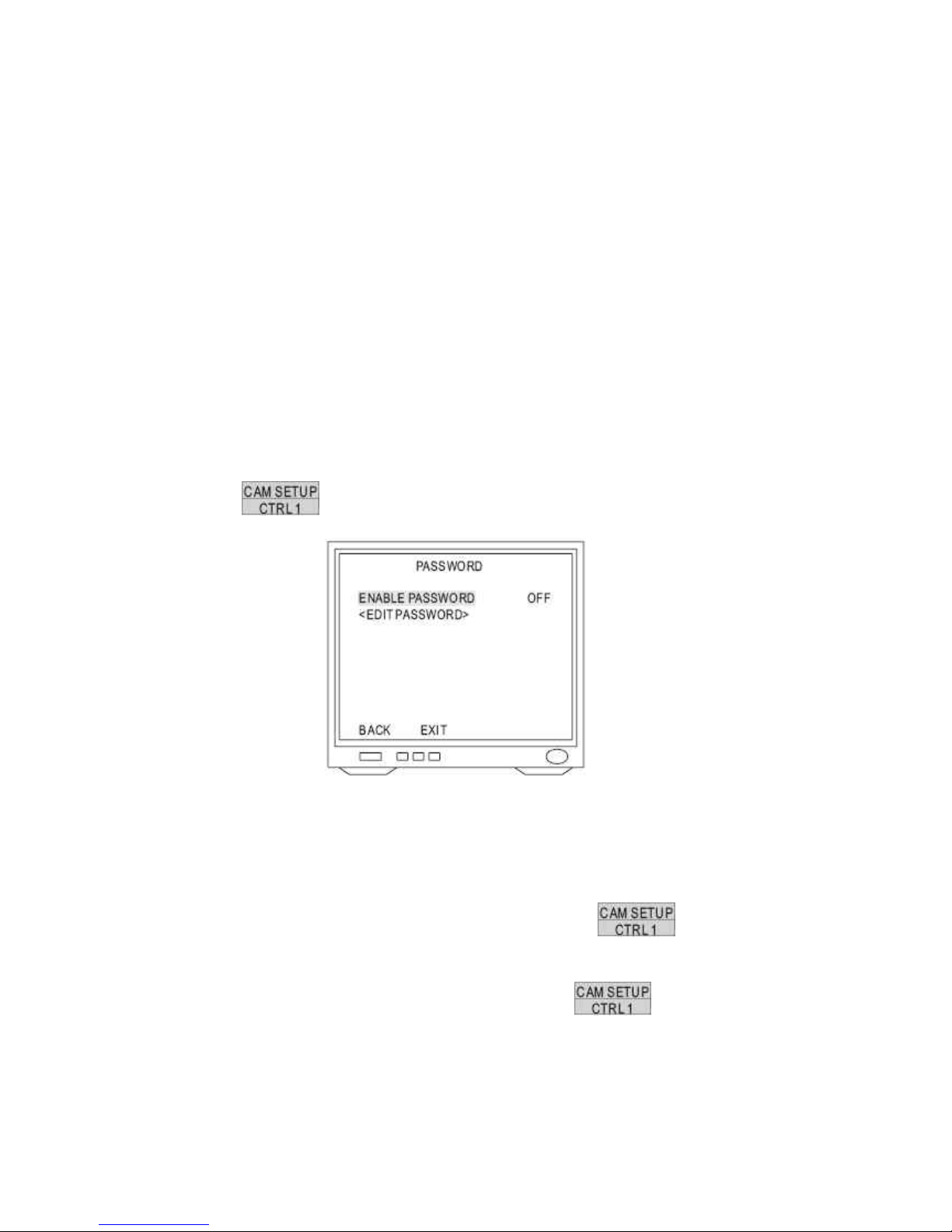
4. Event Mode Setting
Push joystick down to select <EVENT MODE> then push joystick left or right to select
<LOCK> or <RELEASE>
LOCK mode: When multi-alarm is triggered, camera will lock event point of last alarm.
RELEASE mode: When multi-alarm is triggered, camera will do sequence of alarm event
point each 5 sec until event return time stop.
5. Event Return Time Setting
Push joystick down to select <EVENT RETURN TIME> then push joystick left or right to select
event return time (1~99 min)
14.11 Password Function Menu
1. Display the Password Setting Menu
After getting in dome setting menu, push joystick down to select <PASSWORD> then press
key into password function menu.
2. Password Setting
Push joystick down to select <ENABLE PASSWORD> then push joystick left or right to select
<ON> or <OFF>.
3. Edit Password Setting
Push joystick down to select <EDIT PASSWORD> then press
key into edit
password setting.
Push joystick left or right to select number 1~9 then press key to confirm. The
number that is selected will be displayed on the edit column.
Repeat above steps until password setting has been completed.
90
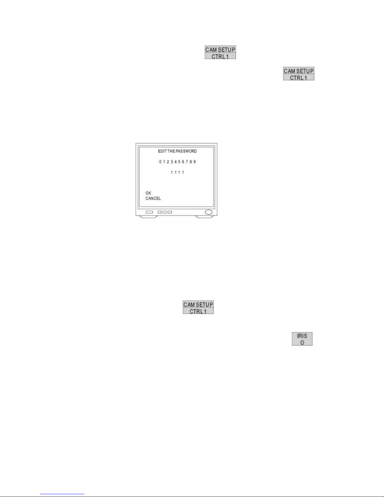
Push joystick down to select <OK> then press key to confirm and back to
password function menu or push joystick down to select <CANCEL> then press
key to cancel password. These numbers of EDIT column will be reset to “1111”.
Note: When edit password setting and camera recording function are simultaneously
performed please stop recording function first; otherwise frame of password setting will be
recorded too.
4. Modify Password
To modify password after editing password completed, please get in <EDIT PASSWORD>
again to edit.
If password function is ON, previous passwords have to enter on the setting menu first and
then do modifying password.
5. Input Password
After password function is ON, press
key to display frame of input password on
the screen.
When protocol is MLP 1, push joystick up or down to select number 0~9 then press
key to confirm. Select numbers will become “*”.
Repeat above steps until passwords have been completed. If password is correct, setting
menu will be displayed.
Note: If does not enter password within 10 sec or input password is wrong, “Invalid password”
will be shown on the screen. Primary password is “1111”.
91
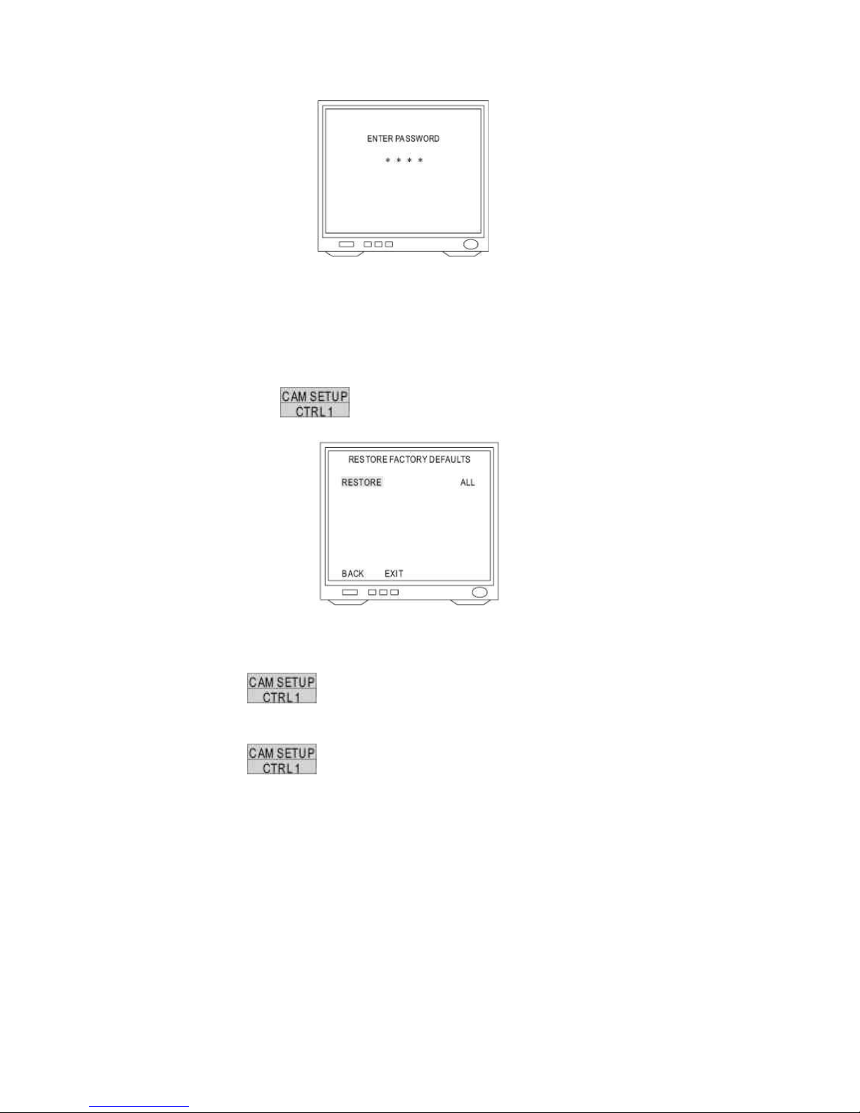
14.12 Restore Factory Defaults
1. Display the Restore Function Initialization Menu
After getting in dome setting menu, push joystick down to select <FACTORY INITIAL> and
then press
key into factory initial setting.
2. Factory Initial for ALL
Push joystick down to select <RESTORE> then push joystick left or right to select <ALL>
Press key to confirm and “Are you sure continue” will be displayed on the
screen.
Press key again then do factory initialization for all.
Note: “PLEASE WAITING FACTORY INITIALIZATION” will show on the screen after
confirmation.
92

3. Factory Initial for Camera
Push joystick down to select <RESTORE> then push joystick left or right to select <CAMERA>
Press key to confirm and “Are you sure continue” will display on the screen.
Press key again then do factory initialization for camera.
Note: Check again. If not press key to confirm within 3 sec, this command will
be canceled.
93

14.13 Schedule Setup Menu
Press key into setup menu.
Push joystick down to select <SCHEDULE SETUP> then press key into schedule
setting.
14.14 Alarm Input Schedule Setting Menu
1. Display the alarm Input Schedule Setting Menu
After getting into schedule setting menu, push joystick down to select <ALARM IN> then
press
key into alarm input schedule setting menu.
2. Start Alarm Input Schedule Setting
Push joystick down to select <STARTUP> then push joystick left or right to select <ON> or
<OFF>.
OFF: Alarm input schedule function is OFF, alarm input trigger will not be limited by schedule
time.
ON: Alarm input schedule function is ON, alarm input trigger will be limited by schedule time.
94

3. Start Time Setting
Push joystick down to select <START> then press key into time setting. Then
push joystick left or right to select start time and press key for next item.
Note: When alarm input schedule function is ON and start time is also beginning, alarm input
trigger will be performed.
4. End Time Setting
Push joystick down to select <END> then press
key into time setting. Then
push joystick left or right to select end time and press key for next item.
Note: When alarm input schedule function is ON and end time is also up, alarm input trigger will be
stopped.
14.15 Start Auto Options Menu
1. Display the startup Auto Options Setting Menu
After getting into schedule setting menu, push joystick down to select <STARTUP AUTO
OPTIONS> then press
key into startup auto options setting menu.
2. Schedule Time Setting
Push joystick down to item 1 to 8 then press key into time setting and push
joystick left or right to select time. Then press key to next item.
95

3. Auto Options Setting
Push joystick down to item 1 to 8 and complete time setting then get into auto setting. Then
push joystick left or right to select auto mode and press
key to confirm.
OFF: No action
STOP: Stop the auto mode
AUTO: Perform auto scan mode
SEQ: Perform preset group mode
TOUR 1: Perform tour 1 list mode
TOUR 2: Perform tour 2 list mode
PATROL: Perform memory patrol mode
Note: 1. When start time began, auto setting mode will start
2. While schedule is performing, if power failed and restored, schedule will not continue to
perform until next schedule time start.
3. While schedule is STOP Mode, if camera is set “Self Return Mode” and “Self Return Time”
is up, camera will perform “Self Return Mode” till next schedule time start.
Example:
1. 12:00, perform SEQ mode
2. 13:00, STOP (If “Self Return Mode” is home, “Home Position Setting” is 1 and “Self Return
Time” is 10 min, camera will perform “Self Return Mode” function and recall preset position 1
at 13:10)
3. 20:00, perform TOUR 1 mode
4. 09:00, STOP (Perform “Self Return Mode” at 09:10)
96

14.16 Daylight Saving Time Menu
1. Display the Daylight Saving Time Setting Menu
After getting into schedule setting menu, push joystick down to select <DAYLIGHT SAVING
TIME> then press
key into daylight saving time setting menu.
2. Start Daylight Saving Time Function Setting
Push joystick down to select <STARTUP> then push joystick left or right to select <ON> or
<OFF>
3. Start Time Setting
Push joystick down to select <START> and press key into setting mode then
push joystick left or right to select start time. Then press key for next item.
4. End Time Setting
Push joystick down to select <END> and press
key into setting mode then push
joystick left or right to select end time. Then press key for next item.
97
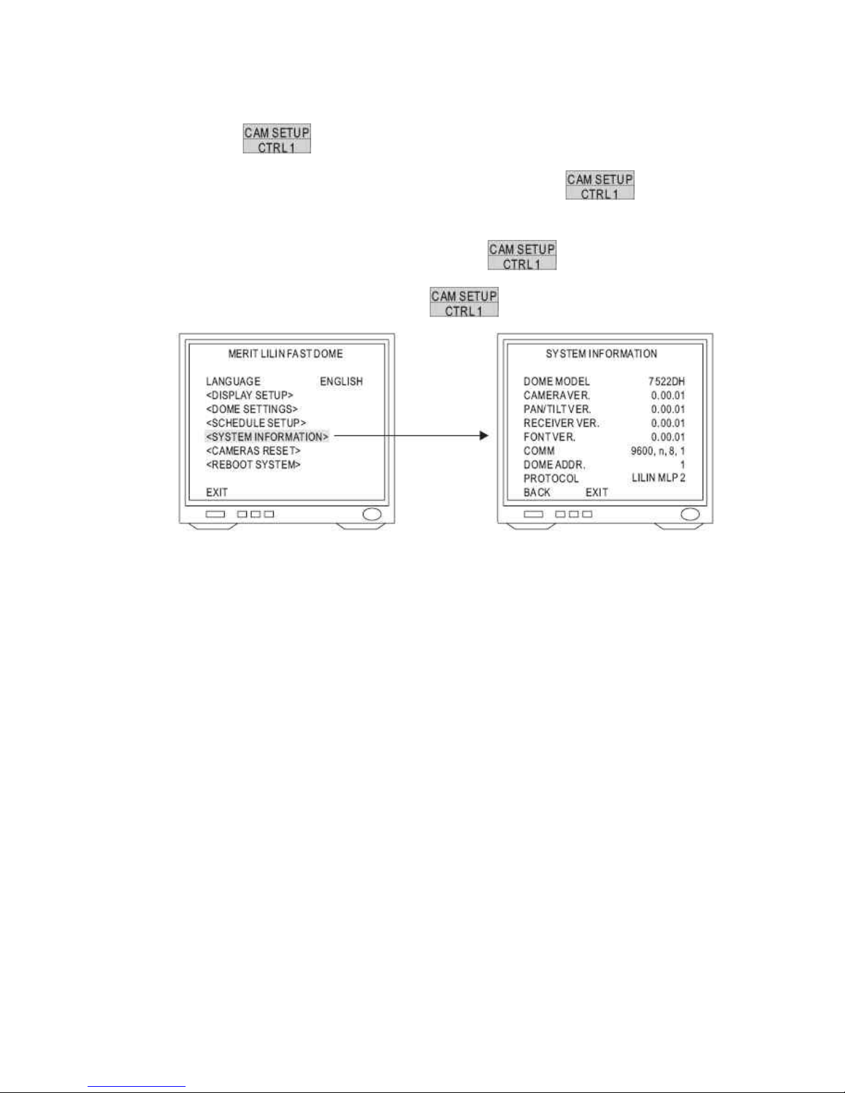
14.17 Display System Information
Press key into Setup Menu
Push joystick down to select <SYSTEM INFORMATION> then press key to
display current system information.
Push joystick down to select <BACK> and then press key to go back or push
joystick down to select <EXIT> then press key to exit setup menu.
Display system information:
1. Fast dome model number
2. Camera, Pan/Tilt, Receiver version
3. Font of OSD version
4. Protocol rate and format
5. Fast dome ID number
6. Protocol version, LILIN717 (MLP1)
98

14.18 Camera Reset
Restart camera module to perform initial setting of camera.
Press
key into setup menu.
Push joystick down to select <CAMERA RESET> and then press key to restart
camera.
Press
key to exit setup menu or joystick down to select <EXIT> and then press
key to exit setup menu.
99

15. Specification
15.1 Operational
Manual Pan / Tilt Speed……………………………………………….0.15°~120°/sec (8 stages)
Preset Position Pan / Tilt Speed………………………………………1°~255°/sec
Preset Position Dwell Time…………………………………………….1~255 sec
Recall Preset Position Pan / Tilt Speed……………………………….360°/sec
180° Instant Flip Rotation Speed………………………………………360°/sec
Pan Rotation………………………………………………………………360° Continuous
Tilt Rotation………………………………………………………………..-6°~+96°
Pan / Tilt Accuracy………………………………………………………..
0.25
Preset Position………………………………………………………..…128 preset positions (memory)
Preset Group……………………………………………………………..4 Groups
Address Setting………………………………………………………….(Corresponding with first 16 presets)
1~64 ID Setting (Protocol is MLP1)
15.2 Camera
Image Device……………………………………………………………..1/4 inch interline transfer CCD
Horizontal & Vertical Pixel……………………………………………….768 x 494 (NTSC)
752 x 582 (PAL)
Scanning System…………………………………………………………2 : 1 Interlace
Horizontal Resolution…………………………………………………….580 TV lines (Monochrome)
520 TV lines (Color)
Minimum Illumination…………………………………………………….0.01 Lux at F1.6 (Monochrome)
0.1 Lux at F1.6 (Color)
S / N Ratio…………………………………………………………………>50dB (AGC OFF)
Synchronization…………………………………………………………..Internal / line Lock
Horizontal & Vertical Synchronization………………………………….15.734KHz/60Hz (NTSC)
15.625KHz/50Hz (PAL)
Auto Gain Control………………………………………………………….0~36dB
Backlight Compensation…………………………………………………..ON / OFF
White Balance……………………………………………………………..2 Auto mode / Manual
Video Output……………………………………………………………….CVBS 1.0Vp-p / 75ΩBNC
100
 Loading...