


1
PixelArt
Version 1.35 firmware
Welcome
PixelArt provides a highly flexible way to convert any
video source from the small screen to a potentially huge
stage. Every part of the system is intelligent and fully
programmable. This makes PixelArt quick to install,
resilient to link failures and easily upgradeable to take
advantage of the latest features.
Contents
Quick start checklist for a typical installation page 2
Key items in the PixelArt system page
2
PixelArt Batten mounting page
3
PixelArt Batten signal cabling page
4
PixelArt Batten power cabling and status indicators page
5
Video Mapper link cabling page
6
Video Mapper video and power cabling page
7
Video Mapper startup page
8
Video Mapper menu page
8
PixelArt Setup Utility page
9
PixelArt Setup Utility: five key functions page 1
0
Crosshairs, grids and solid colour page 1
1
PixelArt fixture orientation page 1
2
PixelArt fixture positioning page 1
3
Troubleshooting page
14
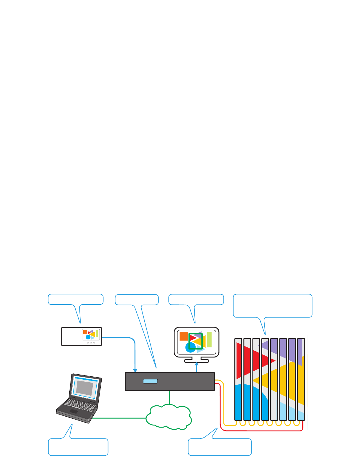
VM 1+1A
or
media
server
IP network
link
video
source
IP network link used to carry out initial
setup and updates, when required
Video out port provides a view of the video
source and the chosen output region (in green)
Protection cable (red) provides an important
backup link in case of main cable (yellow) failure
Each PixelArt fixture displays
its own portion of the chosen
region of the video source
Overview
Checklist
See page 2 for a complete checklist summary of all
actions required to create a new PixelArt installation.
2
Quick start checklist for a typical installation
To create a successful installation, the PixelArt system requires a combination of
mechanical, electrical and software configurations. This quick start checklist runs
through the general order of tasks required for a typical installation:
1 Mount the PixelArt fixtures using standard or custom brackets. see page 3
2 Make daisy-chain power and signal connections between the PixelArt fixtures and also connect the
main signal link from the Video Mapper (V-PORT MAIN socket) to port A of the first PixelArt fixture. see pages 4 & 5
3 Set up a network link between the Video Mapper and the configuration computer. see page 6
4 On the Video Mapper, connect your video source to the appropriate video input
socket (DVI In or VGA In) and attach a DVI monitor to the DVI Out socket. see page 7
5 Power up the PixelArt fixtures, the Video Mapper, the DVI monitor, the video source
and/or the computer.
6 On the computer, run the PixelArt Setup Utility and set the ‘Auto-Number Fixtures’ option to ‘On’
for just five seconds and then switch it ‘Off’. see page 9
7 In the PixelArt Setup Utility, use the ‘Video Input Properties’ (within the ‘Video Mapper’ menu)
option to select the appropriate video input source and define the required video crop area. see page 10
8 In the PixelArt Setup Utility, optionally select the ‘Fixture Discovery’ tab and click the ‘Discover Fixtures’
button to determine the current arrangement of the connected PixelArt fixtures. see page 10
9 In the PixelArt Setup Utility, select the ‘Fixture Mapping’ tab and where necessary, arrange the
PixelArt fixture positions and orientations within the video space to match their physical locations.
When ready, click the Transmit All button to transfer your new mapping details to the
Video Mapper and fixtures. see page 10
10 In the PixelArt Setup Utility, when your configuration is complete, you are strongly recommended to
save the details so that they are immediately available in the future. From the File menu, select the
‘Save Fixture Mapping As’ option to create a .csv file containing your configuration. see page 10
11 On the Video Mapper, when all settings have been made, use the ‘Configuration’ > ‘Save’ option
to ensure that the unit begins using the same settings automatically at every power up. see page 8
12 Connect the standby link (if used) from the last PixelArt fixture to the V-PORT STANDBY socket
of the Video Mapper. see page 4
The PixelArt fixtures should now be displaying the portion of the video source as defined by the
crop area settings. If they are not, then please refer to the Troubleshooting section. see page 14
VM 1+1A
IP network
link
media
server
PixelArt fixtures
(PixelArt Battens are currently
the only type of PixelArt fixture)
DVI output monitor
Video input source
Computer running the
PixelArt Setup Utility
PixelArt fixture MAIN and
STANDBY link cabling
Video Mapper
Key items in the PixelArt system

3
PixelArt Batten mounting
LINK
LIN
K
AC
TIVITY
AC
TIVITY
ER
RO
R
ERR
OR
SOURCE
SOURCE
MAX PO
WER 100W
90 – 240V
A
C
47 – 63H
z
FUSE 3.15A
SLO
W BL
O
W
B
A
www
.pix
elrange
.com
PUSH
PUSH
LINK
A
CTIVITY
ERR
OR
SOURCE
B
A
www
.pix
elr
a
PUS H
Use a safety wire
Ensure that all PixelArt Battens
mounted off-ground are protected
using a secure safety wire (rated
to at least 15Kg, 33lbs) through
the eyelet situated adjacent to the
connection panel.
Supplied Omega brackets
Each PixelArt Batten is supplied with two ‘Omega’
brackets (plus fixings) which attach at the top and
bottom of the rear panel.
For each bracket
1 Insert the two screws into the sockets at the top
left and bottom right holes of the fixing area.
Leave them loose.
2 Securely fit the required clamps to each of the
omega brackets using the supplied bolts, washers and Nyloc® nuts.
3 Offer the bracket to the screws so that the
curved slots engage, then rotate the bracket
anti-clockwise. Tighten the screws.
4 Insert the two twist lock bolts into the top right
and bottom left holes and twist them clockwise
to lock the bracket in place.
5 Double check that each bracket is secure and
use a safety wire (see below).
Optional U-brackets
Optional U-brackets allow greater
tilted angles for PixelArt Battens.
For each bracket
1 Place the supplied fibre washers
between the U-bracket and the
side holes of the PixelArt Batten.
2 Place the metal washers onto the
screws and insert them through the
bracket and the fibre washers into
the side holes.
3 Tighten the screws and double
check that the bracket is secure.
4 Use a safety wire (see left).
IMPORTANT: If a fall is arrested by
the safety chain, the fixture must be
returned to the point of purchase for
checking before it is re-used.
4
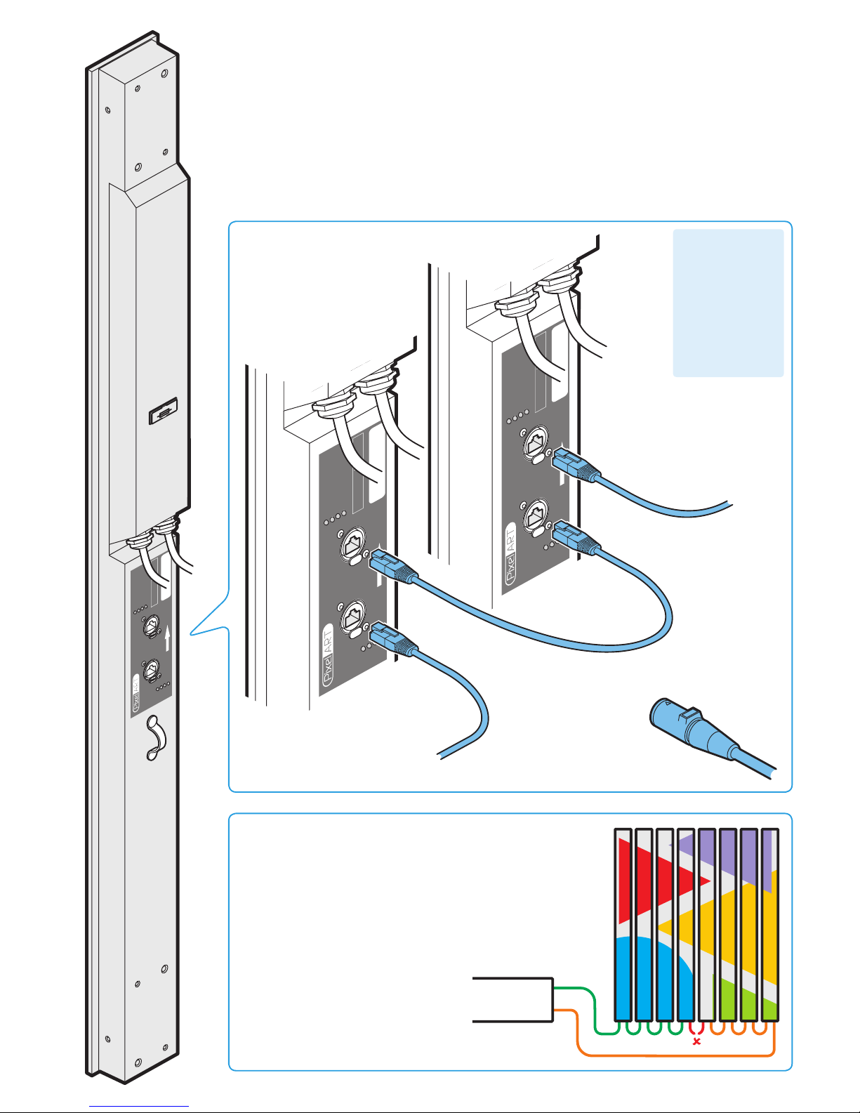
PixelArt Batten signal cabling
• Industry standard Category 5e or 6 (CAT 5e or CAT 6) twisted pair network cable terminated at either
end with standard RJ45 connectors or Neutrik® EtherCon® NE8MC (for more robust linking). Either crossover or straight wired cables may be used for each link - every batten configures the signals accordingly.
• Maximum length of 100 metres (328 feet) between any two battens (or between the Video Mapper and a
batten). Every PixelArt Batten reconditions the signal before transmitting it to the next.
• A maximum of 100 PixelArt fixtures are permissible within a single installation.
•
IMPORTANT: Do not connect ANY PixelArt Batten cabling to an Ethernet network. Such an interconnection
will not cause damage but will result in both the PixelArt system and the network functioning incorrectly.
LINK
LIN
K
AC
TIVITY
AC
TIVITY
ER
RO
R
ERR
OR
SOURCE
SOURCE
MAX PO
WER 100W
90 – 240V
A
C
47 – 63H
z
FUSE 3.15A
SLOW BL
O
W
B
A
www
.pix
elrange
.com
PUSH
PUSH
LINK
LINK
A
CTIVITY
A
CTIVITY
ERR
OR
ERR
OR
SOURCE
SOURCE
MAX PO
WER 100W
90 – 240V
A
C
47 – 63H
z
FUSE 3.15A
SLO
W BLO
W
B
A
www
.pix
elrange
.com
PU SH
PU SH
LINK
LINK
A
CTIVITY
A
CTIVITY
ERR
OR
ERR
OR
SOURCE
SOURCE
MAX PO
WER 100W
90 – 240V
A
C
47 – 63Hz
FUSE 3.15A
SLO
W BLO
W
B
A
www
.pix
elrange
.com
PU SH
PU SH
From Video Mapper MAIN port
(or previous PixelArt fixture)
To port A of the
next PixelArt
fixture
MAIN
STANDBY
Standby cabling
You have the option to run a link cable from the last PixelArt fixture
back to the STANDBY port of the Video Mapper. This provides a
failsafe loop against link cable failure. In such an occurrence, the
system will automatically recognise the loss of signal and re-route
from the other direction up to the lost cable. The battens will all
reconfigure themselves accordingly and operate around the failure
with no loss of output on either side of the break.
IMPORTANT: When setting up a new
installation, do not connect the standby
cable to the Video Mapper until the
PixelArt fixtures have been taken out
of auto-numbering mode. Otherwise
the battens will incorrectly begin auto
numbering themselves from both ends
of the installation.
or
To the
STANDBY port
of the Video
Mapper
(see below)
For more
robust linking,
use Neutrik® EtherCon®
NE8MC connector carriers
Each PixelArt Batten
uses its position
within the daisy
chain cabling link
to automatically
determine its own
number within the
installation. No
switch settings are
used.
5
PixelArt Batten status indicators
LINK: When on, indicates that a valid cable link is
present.
ACTIVITY: Indicates that data is being received - this
indicator is usually always on due to the continually
streamed data.
ERROR: Illuminates when errors are discovered within the data stream.
SOURCE: Indicates where data is being received from:
SHORT FLASH
(known as a ping) - No valid data present.
FAST FLASH
- data received from Video Mapper MAIN port.
SLOW FLASH
- data received from Video Mapper STANDBY port.
DOUBLE FLASH
- data is looped back on same cable, i.e. final bat-
ten (without protection) or batten is adjacent to a cable break.
Note: During normal use, when the main and standby links are connected, the SOURCE indicators for the A and B ports (on every PixelArt
fixture) will confirm to which side of the link loop they are connected:
main (fast flash) or standby (slow flash).
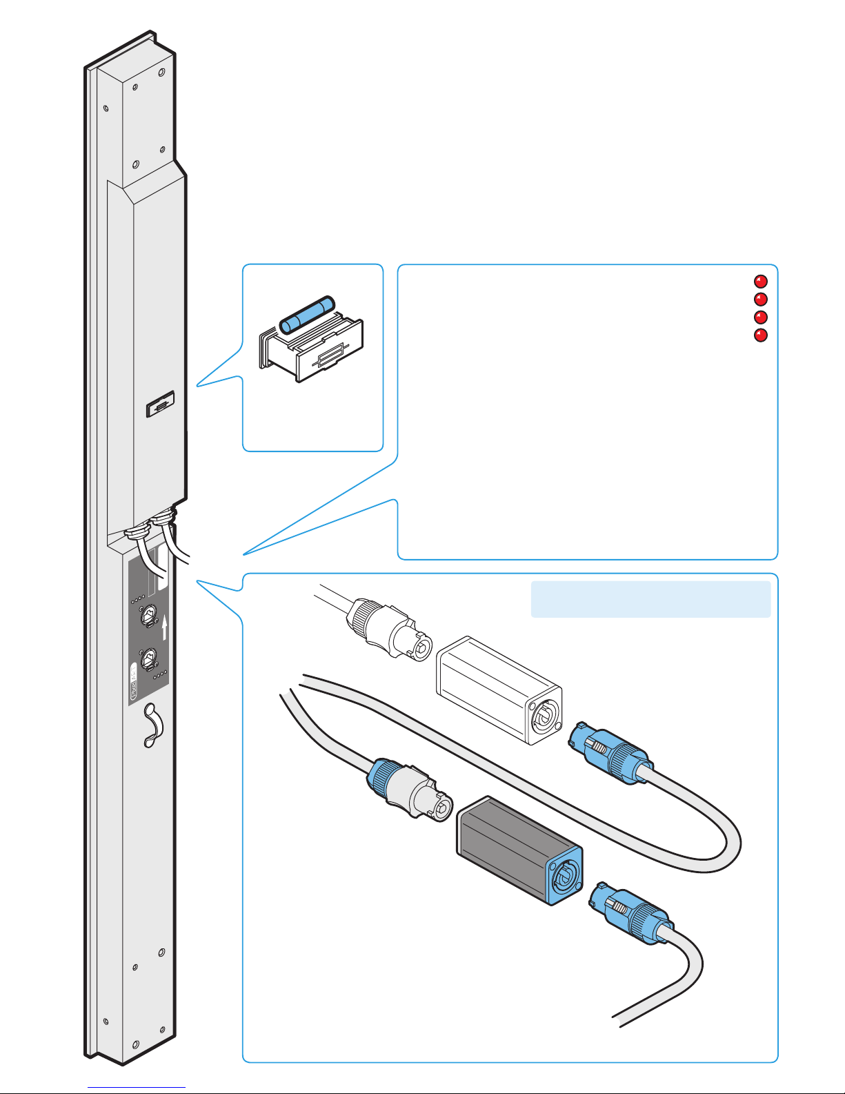
PixelArt Batten power cabling and status indicators
IMPORTANT: Do not connect more than 20 PixelArt Battens in a single power daisy chain.
LINK
LIN
K
AC
TIVITY
AC
TIVITY
ER
RO
R
ERR
OR
SOURCE
SOURCE
MAX PO
WER 100W
90 – 240V
A
C
47 – 63H
z
FUSE 3.15A
SLOW BL
O
W
B
A
www
.pix
elrange
.com
PUSH
PUSH
Power in from source (or
previous PixelArt fixture)
Power out to next
PixelArt fixture
Neutrik® PowerConn®
coupler (NAC3MM)
Size: 5 x 20mm
Rating: 3.15A (slow)
250VAC
PixelArt Batten fuse
Input voltage: 90 to 264V AC, 47 to 63Hz autosensing
Earth leakage: 0.22mA
Connectors required: Neutrik PowerConn® NACFC3A and NACFC3B
Power requirements: @ 230V/50Hz @ 115V/60Hz
Standby 35 watts 35 watts
Maximum (const.) 100 watts 100 watts
Start up (peak*) <40 amps <40 amps
* The peak value occurs only at first power up and lasts only for a period measured in microseconds.
Adjustments may need to be made to supply circuit breakers when (up to 20) PixelArt Battens are
daisy-chained, causing them all to draw the peak simultaneously.
LINK
ACTIVITY
ERROR
SOURCE
IMPORTANT: Do not connect more than 20
PixelArt Battens in a single power daisy chain.
6
Fuse 1A (sl
o
w)
IEC 5x20m
m
90 - 264V
A
C
47 - 63 Hz
V
-POR
T 1
NETW
ORK
(STANDBY)
D
VI Out
MAX PO
WER 60W
Disconnect mains bef
ore changing fuse or remo
ving co
ve
r
No User ser
viceab
le par
ts
D
VI In
V
GA In
G
R
B H
V
V
-POR
T
0
(MAIN)
Activity
Link
)Statu
s
PUS H
Activity
Link
)Statu
s
PUS H
Activity
Link
)Statu
s
PUS H
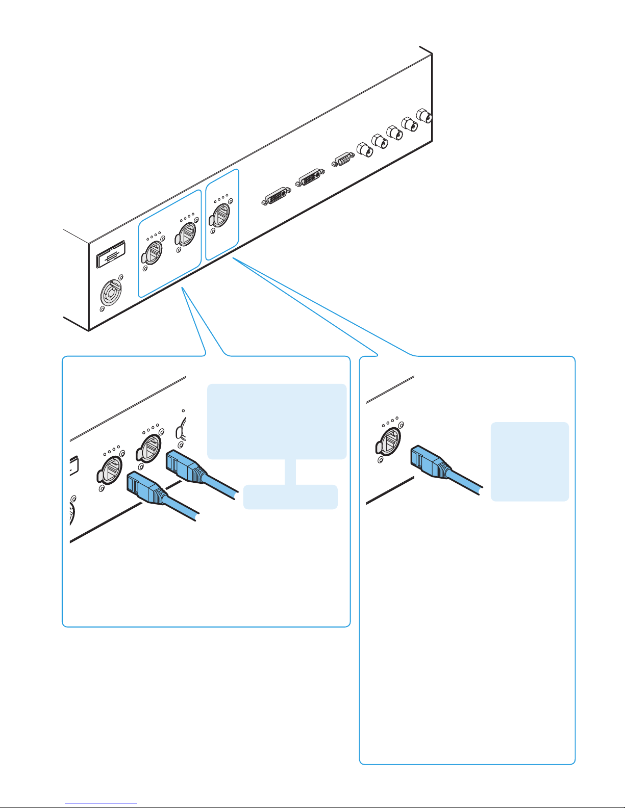
Video Mapper link cabling
o
w)
C
z
V
-POR
T 1
NET
(ST
ANDBY)
V
-POR
T
0
(MAIN)
Activity
Link
)Statu
s
P
US H
Activity
Link
)Statu
s
P
US H
Activity
P
US H
MAIN signal output
to first PixelArt fixture
V-PORT links to PixelArt fixtures
V-PORT status indicators
LINK: When on, indicates that a valid cable link is present.
ACTIVITY: Indicates that data is being transmitted - this indicator
is usually always on due to the continually streamed data.
STATUS: Reserved for future use.
Computer network link
NETW
ORK
Activity
Link
)Statu
s
PU SH
Used to link a computer to the Video
Mapper, primarily for initial configuration
purposes.
You can either connect your computer directly to the
Video Mapper or indirectly via a network router/hub.
Use CAT5e or CAT6 cable (see crossover note above).
Depending on its configuration, the Video Mapper
will either attempt to automatically find itself a suitable network address or will use a pre-configured
setting (determined by ‘Network Settings’ within the
Video Mapper menu - see page 8).
During automatic searches, the Video Mapper will
try to configure itself according to the connected
network (using DHCP or Dynamic Host Configuration
Protocol). In automatic mode, if no other devices are
discovered, the Video Mapper will timeout and use a
default address and subnet mask, usually: 2.0.0.20
and 255.0.0.0 respectively.
Note: The search will take longer if no network is
connected.
Network status indicators
LINK: When on, indicates that a valid cable link is
present.
ACTIVITY: Indicates that data is being transceived.
STATUS: Reserved for future use.
STANDBY signal output
to final PixelArt fixture
Note: Do not connect the STANDBY
link until the PixelArt fixtures have
been fully configured via the
PixelArt Setup Utility and taken out
of auto number mode - otherwise
the battens will number themselves
incorrectly.
Connection to PC:
Use a crossover
network cable.
Connection to a
router/hub: Use
a straight through
network cable.
7
ore changing fuse
o
ser
viceab
le par
ts
D
VI In
V
GA In
R
D
VI Out
MAX PO
WER 60
Disconnect main
No User ser
vicea
DV
I
Fuse 1A (sl
o
w)
IEC 5x20m
m
90 - 264V
A
C
47 - 63 Hz
V
-POR
T 1
NETW
ORK
(STANDBY)
D
VI Out
MAX PO
WER 60W
Disconnect mains bef
ore changing fuse or remo
ving co
ve
r
No User ser
viceab
le par
ts
D
VI In
V
GA In
G
R
B H
V
V
-POR
T
0
(MAIN)
Activity
Link
)Statu
s
PUS H
Activity
Link
)Statu
s
PUS H
Activity
Link
)Statu
s
PUS H
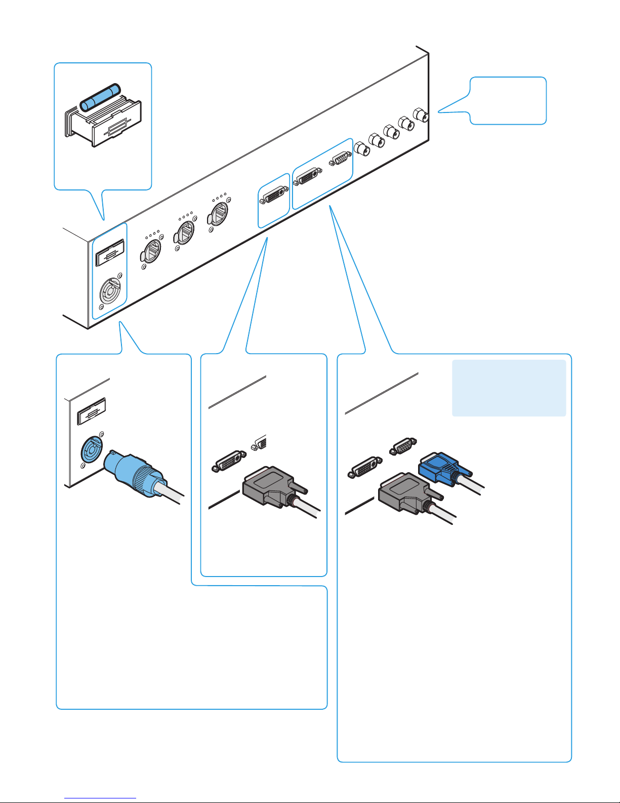
Video Mapper video and power cabling
Power input
Video monitor output
Fuse 1A (sl
o
w)
IEC 5x20m
m
90 - 264V
A
C
47 - 63 Hz
Size: 5 x 20mm
Rating: 1A (slow)
250VAC
Video Mapper fuse
BNC connectors
reserved for future
use
DVI/D output for video
monitor. Essential during
configuration for defining the
video region to be sent to the
PixelArt fixtures.
Video input
IMPORTANT: To achieve best
quality results from PixelArt
fixtures, use only digital DVI
video inputs wherever possible.
Analogue VGA input
Digital DVI/D input
Video input resolution and frequency
The link between the Video Mapper and the PixelArt
fixtures has a maximum bandwidth of 120,000 pixels at
25Hz (frames per second). This equates to a quarter of an
800 x 600 video input or just under half of a 640 x 480
input. The actual portion of the video input that is sent to
the PixelArt fixtures is determined using the Crop Area settings within the PixelArt Setup Utility (see page 9).
The Video Mapper automatically takes every third frame
from the video input. Therefore, the optimum video input
resolution is 75Hz (in order to achieve an ideal 25Hz (25
frames per second) output to the PixelArt fixtures).
Supported frequencies
The following frequencies are supported by the Video
Mapper:
640x480 @ 75Hz
720x576 @ 75Hz
800x600 @ 75Hz
1024x768 @ 75Hz
Input voltage: 90 to 264V AC, 47 to 63Hz autosensing
Earth leakage 0.22mA
Connector required: Neutrik PowerConn® NACFC3A
Power requirements: @ 230V/50Hz @ 115V/60Hz
Maximum (const.) 60 watts 60 watts
Start up (peak*) <40 amps <40 amps
* The peak value occurs only at first power up and lasts only for
a period measured in microseconds.
Power requirements

8
Video Mapper startup
As soon as power is applied to the Video Mapper, it will either attempt to
automatically find itself a suitable network address or will use a pre-configured
setting as determined by ‘Network Settings > Network Setup > Set Network
Mode’.
During automatic searches, the Video Mapper will try to configure itself according to the connected network (using DHCP or Dynamic Host Configuration Proto-
col). In automatic mode, if no other devices are discovered, the Video Mapper
will timeout and use a default address and subnet mask, usually: 2.0.0.20 and
255.0.0.0 respectively.
You can preset a network address and subnet mask using ‘Network Settings >
Network Setup > Set IP Address / Set Subnet Mask’.
Note: The automatic search will take longer if no network is connected.
Video Mapper menu
The Video Mapper menu allows you to configure various aspects of operation.
To enter and use the menu
1 From the initial screen display that shows the firmware version and network
address, press the ENTER ( ) button to enter the menu. The top line of the
screen will show the first menu item: Pattern Tools.
2 Use the
DOWN ( ) and UP ( ) buttons to move between the menu options
and press the ENTER ( ) button when the required menu option is displayed.
3 Within the chosen menu option, again, use the
DOWN and UP buttons to dis-
play the required sub-option (or setting) and press the ENTER button to select
it. When a setting is changed, the display will show SET as confirmation.
4 Use the
BACK ( ) button to exit from a menu option to the previous level.
Video Mapper
firmware version
PixelArt 0x 135
Starting
PixelArt
BACK
ENTER DOWN UP
IMPORTANT: When making changes that you
wish to keep after the next power up, visit the
‘Configuration’ option and select ‘Save’. This
is especially vital when changing network addresses as it may affect the next power up.
Pattern Tools
Controls the Video Mapper’s internal effects generator
and enables you to superimpose a grid, solid colour
fills and/or a crosshair onto the PixelArt fixture display.
The grid and the crosshairs are particularly useful when
configuring new installations - see page 11.
Video Settings
Determines various aspects of the video input and
output, including the main video source, the input resolution and information items that can be overlaid (On
Screen Display or OSD) onto the DVI output monitor
screen.
Network Settings
Allows you to adjust the network address and subnet
mask settings used by the Video Mapper when linked to a
computer. Address setting is manual as standard.
Information - Provides details about the revisions for the
various major components within the Video Mapper.
Blackout - Enables you to immediately place all connected PixelArt fixtures into blackout.
Fixture Settings - Allows you to place the connected
fixtures in and out of auto-numbering mode.
Configuration - Allows you to save, load or reset all
Video Mapper settings within internal non-volatile memory.
Menu layout
Pattern Tools Grid Grid On/Off
Grid Colour
Grid Pitch
Solid Colour Set Colour
Colour Cycle
Crosshair Crosshair On/Off
Crosshair Colour
Crosshair Area
Crosshair X
Crosshair Y
Video Settings Input Source Pattern Gen.
DVI Port
VGA Port
Input Resolution
OSD Settings OSD On/Off
OSD Colour
OSD X
OSD Y
Fixture Settings Auto Num On/Off
Network Settings Show IP Address
Show Subnet Mask
Network Setup Set Network Mode
Set IP Address
Set Subnet Mask
Configuration Load
Save
Reset
Information Firmware Version
Hardware Version
Graphics Version
Blackout Fixtures On / Fixtures Off

9
PixelArt Setup Utility
The PixelArt Setup Utility is used during initial configuration and can be run on any Windows® XP or Vista -based computer (with Java6 or
later) or any Apple Mac (with Java 5 or later) that is network linked to the Video Mapper.
Video Mapper communication
Check that the network address shown in the Video Mapper IP address section matches the address shown in the startup display of
the Video Mapper. If the network addresses do not match or there
is no address shown in the section, then there may be a communication problem. Please see the Troubleshooting section on page 14
for details.
Starting the PixelArt Setup Utility
1 Insert the supplied disc into CD-ROM drive of the
connected computer.
2 View the contents of the CD-ROM and run the PixelArt Setup
Utility application.
When the utility starts, you will see the main screen
Five key functions for new installations
Within the PixelArt Setup Utility, there are five key functions
that you need to perform for any new installation:
1 Auto-number the PixelArt fixtures.
2 Confirm the source video input to the Video Mapper.
3 Define the video crop area.
4 Map the PixelArt fixtures within the crop area video space.
5
Save settings in Video Mapper flash memory
Please see the next page for details
about how to perform each key function
Ü
Use this menu to confirm the source
video input, define the crop area and
save all settings to the Video Mapper
Use this menu to
save or load fixture
mapping files
Shows the network address of the
Video Mapper. Use Search to find
a newly connected Video Mapper
Use this option to
enable and disable
fixture auto numbering
Use these buttons to
send all or some fixture
mapping details to the
PixelArt fixtures
Use this button to
discover the current x,y
and orientation values
for all of the connected
PixelArt fixtures
Use this button
to create a visual
representation of the
fixture mapping (not
currently implemented)
The three main tabs
allow you to: see the
preliminary arrangement of the PixelArt
fixtures; define new arrangements and view
a visualisation
The central area shows
the fixture positions
and orientations,
either as values or as
a visual representation depending on the
chosen tab
Set the video input
source here
Configure the crop area size and position here.
The Total field will turn red if your size settings
exceed the 120,000 pixel maximum.
Note: When defining a crop box, ensure that it
remains within the total video input area.
Click the ‘Video Mapper’ menu
& select ‘Video Input Properties’
Use the ‘Initialise Fixtures’ option
within the ‘Tools’ menu if one or
more fixtures behave erratically

10
1
Auto-Numbering fixtures
When beginning a new installation, it is vital to briefly place the
connected PixelArt fixtures into auto-numbering mode so that they
can assign themselves unique fixture numbers, according to their positions within the daisy chain cable link. Once complete you do not
need to auto number the PixelArt fixtures again, unless any fixtures
are added, removed or moved.
Note: It is important that the Auto-Number Fixtures option is switched
Off before the standby link is made from the final PixelArt fixture to
the Video Mapper.
To auto-number the PixelArt fixtures
1 In the lower left corner of the PixelArt Setup Utility window, in the
‘Auto-Number Fixtures’ section, click the ‘On’ option.
2 After five seconds, click the ‘Off’ option.
2
Confirming the source video input
The Video Mapper provides a choice of two video inputs: DVI digital
or VGA analogue. Of the two input types, the DVI option provides a
much greater image quality. You need to confirm to the Video Mapper which input is being used.
To confirm the source video input
1 In the PixelArt Setup Utility window, click the ‘Video Mapper’
menu and select the ‘Video Input Properties’ option to display the
Video Input Setup window.
2 In the Video Input section of the window, select either the DVI or
the RGB/VGA option, as appropriate.
If you select the RGB/VGA option, then you will also need to
confirm the resolution of the video source. Click the down arrow
of the Resolution box and select the appropriate setting.
3 When the appropriate settings have been made, click the Set
button to send the data to the Video Mapper.
3
Defining the video crop area
The PixelArt fixtures display a portion of the total input video source
and that portion is defined by the crop area. Once defined, all PixelArt fixture coordinates are determined relative to the top left hand
corner of the crop area.
Note: The Video Mapper provides a crosshair tool to assist you to
relate positions on the output video monitor (and the PixelArt fixtures)
with pixel coordinates - see the next page for details Ü
To define the crop area
1 In the PixelArt Setup Utility window, click the ‘Video Mapper’
menu and select the ‘Video Input Properties’ option to display a
dialog box (shown on page 9).
2 In the ‘Crop Area’ section, enter the required position of the top
left corner of the crop area using the x and y fields. In each case,
you are entering the number of pixels across (x) and down (y)
from the top left corner of the total video space area (i.e. 800 x
600; 640 x 480, etc.).
3 Now define the size of the crop area using the Width and Height
fields. Again, these are measured in pixels and the total area
must not exceed 120,000, (e.g. width = 400 x height = 300)
which is the upper limit that can be sent to the PixelArt fixtures.
Note: Ensure that your combined crop area size and position
settings result in the crop area lying within the overall video input
space, i.e. so that a portion of the crop area does not overhang
any of the video space boundaries.
4 When the appropriate values have been entered, click the Set
button to send the data to the Video Mapper. On the DVI monitor
you will see the green outlined crop area change within the total
video space to reflect your values. This is now the screen area
that will be sent to the PixelArt fixtures.
4
Fixture mapping
Thanks to the flexible manner in which the PixelArt fixtures are designated, you can configure any PixelArt fixture to occupy any position
(and any 90 degree rotation) within the video space defined by the
crop area. This is called fixture mapping and is a key feature of the
PixelArt system. There are two main ways to determine fixture mapping:
• By using just the PixelArt Setup Utility, or
• By using a spreadsheet and the PixelArt Setup Utility.
See also:
Fixture orientation and positioning pages 12 and 13
To perform a fixture discovery
When beginning a new installation, it is common, but not essential to discover the current configuration of all connected PixelArt
fixtures. From this starting point it can be more straightforward to
adjust the configuration to suit your required layout, particularly if
the PixelArt fixtures have been wired in a logical sequence.
1 In the PixelArt Setup Utility window, click the ‘Fixture Discovery’
tab.
2 Click the ‘Discover Fixtures’ button. Within a short while, the x,
y and orientation coordinates for each PixelArt fixture will be
updated within the list.
To map fixtures using only the PixelArt Setup Utility
1 In the PixelArt Setup Utility window, click the ‘Fixture Mapping’
tab.
2 For each fixture entry, click your cursor in the required x, y or
Orientation field and edit the entry, as necessary. Press your
keyboard’s Enter key to fix the new value.
3 Repeat step 2 for each entry that needs to be changed.
4 When all changes have been made, either click the ‘Transmit
All’ button or highlight one or more fixture entries and click the
‘Transmit Selection’ button.
To map fixtures using a spreadsheet and the utility
1 Use a spreadsheet such as Microsoft Excel to create a simple
file with four columns and as many rows as there are PixelArt
fixtures. From left to right the columns represent: Fixture number,
x, y and orientation.
Alternatively, in the PixelArt Setup Utility, save the current discov
ered fixtures to a ‘.csv’ file (using the ‘Save Discovered Fixture
Map As’ option in the File menu), then open that file within your
spreadsheet and use it as a template.
2 Once your mapping details are complete, save the file with a
‘.csv’ file ending.
3 In the PixelArt Setup Utility, open the saved file using the ‘Load
Fixture Mapping’ option in the ‘File’ menu. The new details will
be shown within the ‘Fixture Mapping’ tab.
4 Click the ‘Transmit All’ button to send the data to the fixtures.
5
Save settings in Video Mapper flash memory
Once all settings have been made and sent to the Video Mapper,
you need to ensure that they are also transferred to the Video Mapper’s non-volatile flash memory so they are instantly available at the
next power up (and can be used independently of the computer).
To save settings in Video Mapper non-volatile memory
You can do this in two ways, either:
• In the PixelArt Setup Utility window, click the ‘Video Mapper’
menu and select the ‘Save Current Setup to Video Mapper’ option to transfer all configuration details, or
• In the Video Mapper menu, select ‘Configuration’ and select the
‘Save’ option.
PixelArt Setup Utility: five key functions
11
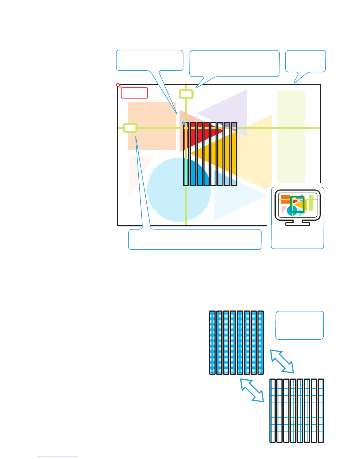
The grid is expandable from 0 pixel
spacing to 20 pixel
spacing
Crosshairs, grids and solid colour
The Video Mapper is able to generate and superimpose items over the source video input to assist you during configuration. As well as being able to apply solid colours to the whole video space, you will find the crosshairs particularly useful when defining the crop area and the
grid invaluable when initially testing the fixture mapping.
Using crosshairs when defining the crop area
When configuring a new installation it
is necessary to define the size and position of the crop area (within the total
video space) that will form the region
displayed by the PixelArt fixtures.
The Video Mapper provides a set
of crosshairs to assist in locating the
required coordinates of the crop area.
The crosshairs are superimposed on the
video input as seen on the connected
DVI video monitor and also, when they
enter the crop area, on any connected
PixelArt fixtures that are mapped into
the same area.
You have the choice of viewing crosshair coordinates relative to the entire
video space origin (absolute) or relative to the origin of the crop area. The
former is useful when defining the crop
area, the latter is more useful when testing/locating areas once the crop area
has been fully defined.
The current x or y coordinates (absolute or crop area) of the crosshairs are
shown on the Video Mapper display
and these can be used directly within
the PixelArt Setup Utility.
To use the crosshairs
1 On the Video Mapper, enter the
Pattern Tools menu and select the
‘Crosshair On/Off’ option. Choose
the ‘On’ setting.
Note: You can also change the
colour for the crosshairs.
2 Select the ‘Crosshair Area’ option and choose either ‘Absolute’ or ‘Crop Area 1’ as required.
3 Select the ‘Crosshair X’ or ‘Crosshair Y’ option, as appropriate, and increase or decrease the position value until the crosshair arrives at
the required position, as seen on the monitor and possibly the PixelArt fixtures.
4 Read off the value shown on the display and use this when defining the crop area or locating a section within the crop area.
5 Repeat steps 3 and 4 for the other crosshair.
Using the grid when fixture mapping
The grid feature provided by the Video Mapper is useful when initially mapping
fixtures or when testing fixtures because it can quickly highlight any fixtures that
have been mapped or mounted incorrectly.
To use the grid
1 On the Video Mapper, enter the Video Settings menu and select the Input
Source option. Choose the ‘Pattern Generator’ option.
2 Now enter the Pattern Tools menu and select the ‘Grid On/Off’ option.
Choose the ‘On’ setting.
Note: You can also change the colour for the grid.
3 Select the ‘Grid Pitch’ option and adjust the grid spacing from 0 to 20. If
the PixelArt fixtures are correctly mapped and positioned, you should see a
contiguous grid across all fixtures.
Note: When you have finished with the grid, you need to change the input
source back to either ‘DVI port’ or ‘VGA port’ within the ‘Video Settings’ >
‘Input Source’ menu.
Absolute
origin (0,0)
132
138
Crop area origin point = 0,0
Absolute position = 135,128
Crop area and crosshairs shown on DVI
output monitor
X crosshair - the position value (pixels
across from the left - relative to either the
absolute origin or the crop area origin)
is shown on the Video Mapper menu
Total input video
space defined by
the crop area
Y crosshair - the position value (pixels down from the top -
relative to either the absolute origin or the crop area origin)
is shown on the Video Mapper menu

12
PixelArt fixture orientation
You can physically arrange each PixelArt
fixture in any of four rotational positions:
0, 90, 180 or 270 degrees, going anticlockwise relative to the horizontal plane.
To match the physical arrangements, you
need to inform the PixelArt fixtures themselves (via the PixelArt Setup Utility and
the Video Mapper) which way they are
positioned.
Each PixelArt fixture maintains a logical
origin point at its top left hand corner, irrespective of its rotation. This is to simplify
fixture positioning information and also to
ensure that the video image remains true,
regardless of how each PixelArt fixture is
arranged.
In the representations shown here, the
power cables are used to indicate the
direction of the fixture.
Origin point
Orientation:
0 degrees
Origin point
Orientation:
90 degrees
Origin point
Orientation:
180 degrees
Origin point
Orientation:
270 degrees
Input image
Orienting PixelArt fixtures
You can set the orientation for each PixelArt fixture using either:
• The Fixture Mapping tab of the PixelArt Setup Utility,
or
• A spreadsheet (such as Microsoft
®
Excel®) to create a (.csv)
file that can be loaded into the PixelArt Setup Utility.
See page 13 for details.

13
PixelArt fixture positioning
You can place each PixelArt fixture
anywhere within the video space
defined by the crop area.
Each PixelArt fixture’s position
within the video space is totally
independent of its location in the
control cable daisy chain, although
it is common for the two to coincide.
Three values are required to position a PixelArt fixture within the
video space:
• a horizontal
x coordinate
(measured in pixels)
• a vertical
y coordinate
(measured in pixels),
and
• an orientation
(measured in degrees)
The origin point of the video space
is always in the top left hand corner
(of the crop area) and similarly, the
origin point for each PixelArt fixture
is also always in the top left hand
corner, regardless of their respective rotation settings.
x=0
y=0
1
4
7
10
13
8
9
253
6
12
11
x: 0
y: 0
o: 90
x: 6
y: 0
o: 90
x: 12
y: 0
o: 90
x: 42
y: 20
o: 0
x: 42
y: 26
o: 0
x: 42
y: 32
o: 0
x: 60
y: 22
o: 90
x: 36
y: 116
o: 0
x: 39
y: 120
o: 0
x: 42
y: 124
o: 0
x increasing
y increasing
x: 6
y: 72
o: 90
x: 12
y: 72
o: 90
Positioning PixelArt fixtures
There are two mains ways to determine the PixelArt fixture positions:
• Use the Fixture Mapping tab
within the PixelArt Setup Utility
or
• Use a spreadsheet (e.g. Microsoft
®
Excel®)
to create a (.csv) file that can be loaded
into the PixelArt Setup Utility
Fixture
Number
x
coordinatey coordinate
Orientation
Note: Each PixelArt Batten
measures 6 x 72 pixels
x: 0
y: 72
o: 90
Video space defined
by the crop area

Documentation by Corporate Text & Design (www.ctxd.com)
Release 1.35d
www.pixelrange.com
UK +44 (0)1905 363600
sales@pixelrange.com
USA +1 865 675 3955
salesUSA@pixelrange.com
Troubleshooting
No video output on PixelArt fixtures
• Check that the Blackout option is not active on the Video Mapper.
• Check the video input to the Video Mapper.
• Check that the fixtures are correctly mapped within the crop area.
• Check the indicators at the rear of the PixelArt fixtures for general
illumination and also for error flashes.
• Check the power input fuses and the power feed to the fixtures.
Incorrect or garbled output from one or more PixelArt fixtures
• In the PixelArt Setup Utility on the computer, click the ‘Tools’ menu
and select the ‘Initialise Fixtures’ option.
No communication between computer and Video Mapper
• Check network connection and also network address of computer.
• Disable all network adapters (including wireless and FireWire
links) on the computer except the one that is connected to the
Video Mapper.
• If the Video Mapper is connected directly to the computer (i.e.
not via a network router or hub), ensure that the cable used has
crossover links (i.e. pin 1 to pin 3, pin 2 to pin 6, etc.) rather than
straight through connections (i.e. pin 1 to pin 1, pin 2 to pin 2,
etc.).
• Check that the computer’s firewall is not blocking network access
for the Video Mapper. If so, make an exception for port 6455,
which is used by the Video Mapper. Note: Changes to firewall
settings should only be made by those competent to do so.
Settings keep being lost from the Video Mapper
• After making changes within the Video Mapper menu, be sure to
go to the ‘Configuration’ section and choose the ‘Save’ option.
This will store all settings within non-volatile flash memory. This is
particularly important for network settings as these could affect the
next power up of the Video Mapper.
PUSH
PUSH
90mm
(3.5”)
64mm
(2.5”)
1080mm
(42.5”)
440mm
(17.25”)
285mm
(11.25”)
90m
m
(3.5”)
P
USH
PUSH
PUSH
Dimensions
 Loading...