

Page 1
PRODUCT
MANUAL
Video Processor / Scaler PE1000
Page 2

Page 3

1
Contents
Table of Contents
1 Introduction 3
About Plasma Enhancer® PE1000 4
Installation and Setup Overview 5
Familiarizing with Plasma Enhancer® PE1000
Front and Side Panels 6
Rear Panel 7
Remote Controls
Full Feature Remote Control 8
Spouse Friendly
Remote Control - TV Commander 9
®
2 Installation 10-14
Hardware Installation 10
Compatible Equipment 10
Power Connection 11
Display Device Connection 11
AV Device Connection 12
Antenna Connection 12
Alternative AV Receiver / Processor Connection 13
Audio Out Connection 14
Product Registration 14
3 Basic System Setup 15-17
Image Setup 15
Display Setup 16
TV Setup 17
System Setup 18
4 Advanced Setup 19-21
Image Setup 19
Input Select 19
Picture 19
Aspect Ratio 19
Deinterlacer 19
Overscan 19
Y/C Delay 20
Noise Reducer 20
TrueLife 20
NLS Config 20
Position 20
Profile 20
Page 4

Table of Contents
Contents
System Setup 21
Spouse Remote 21
Audio Mapping 21
AV1 Config 21
Analog Output 21
Audio Channel 21
Information 21
TV Commander 22
Show Advanced Option 22
Factory Setting 22
5 Important Information 23-26
Troubleshooting 23
Technical Specifications 24
Safety Information 25
Support and Warranty Information 26
6 Note 27
Page 5

3
Introduction
Thank you for purchasing the Plasma Enhancer PE1000, featuring the most
powerful video processing technologies by Pixel Magic Systems. This product
will deliver a high performance processing and scaling for the most life-like
picture quality and a superb home theatre viewing experience.
®
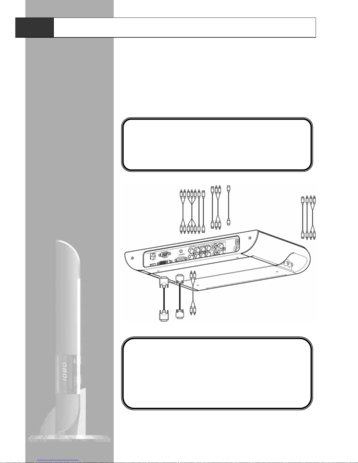
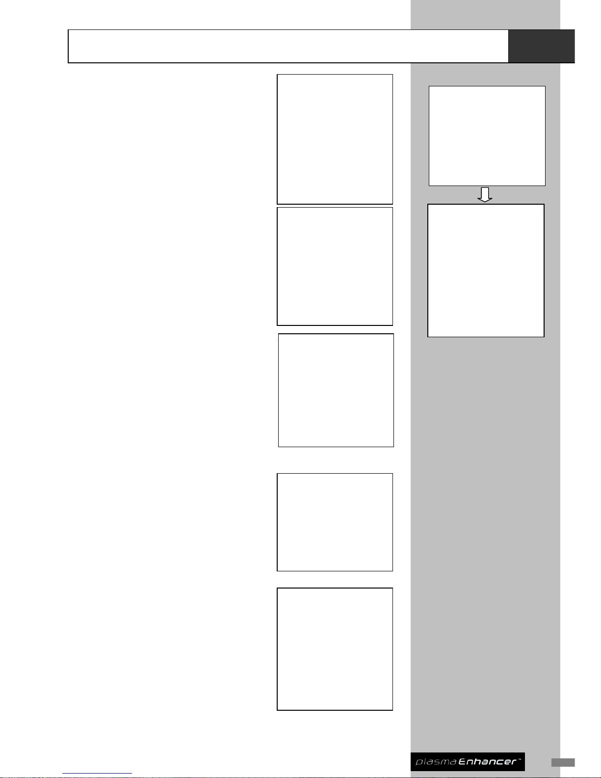
The carton of your Plasma Enhancer
should contain the following items:
®
1. Plasma Enhancer
®
PE1000 Video Processor
2. Full Feature Remote Control
3. Spouse Friendly
®
Remote Control
4. Transformer with mains power lead
5. Plasma Enhancer
® Vertical Stand
6. Audio and Video Cable
7. Plasma Enhancer
®
PE1000 Product Manual
Please contact your Plasma Enhancer
retailer immediately if any of the above
items are missing.
®
This product manual will help to familiarize with the; set-up, configuration, AV
device connection, and operation of your Plasma Enhancer
.
®
The Technical Specifications section at the end of this user guide summarizes
the key features and performance of the Plasma Enhancer
.
®
Should you have any questions during the setup or operation of this Plasma
Enhancer
, you should first contact your authorized Plasma Enhancer reseller
for assistance. You can also contact Pixel Magic Systems directly for technical
assistance:
® ®
Email
info@pixelmagicsystems.com
Web www.pixelmagicsystems.com
Enjoy!
Page 6

Overview
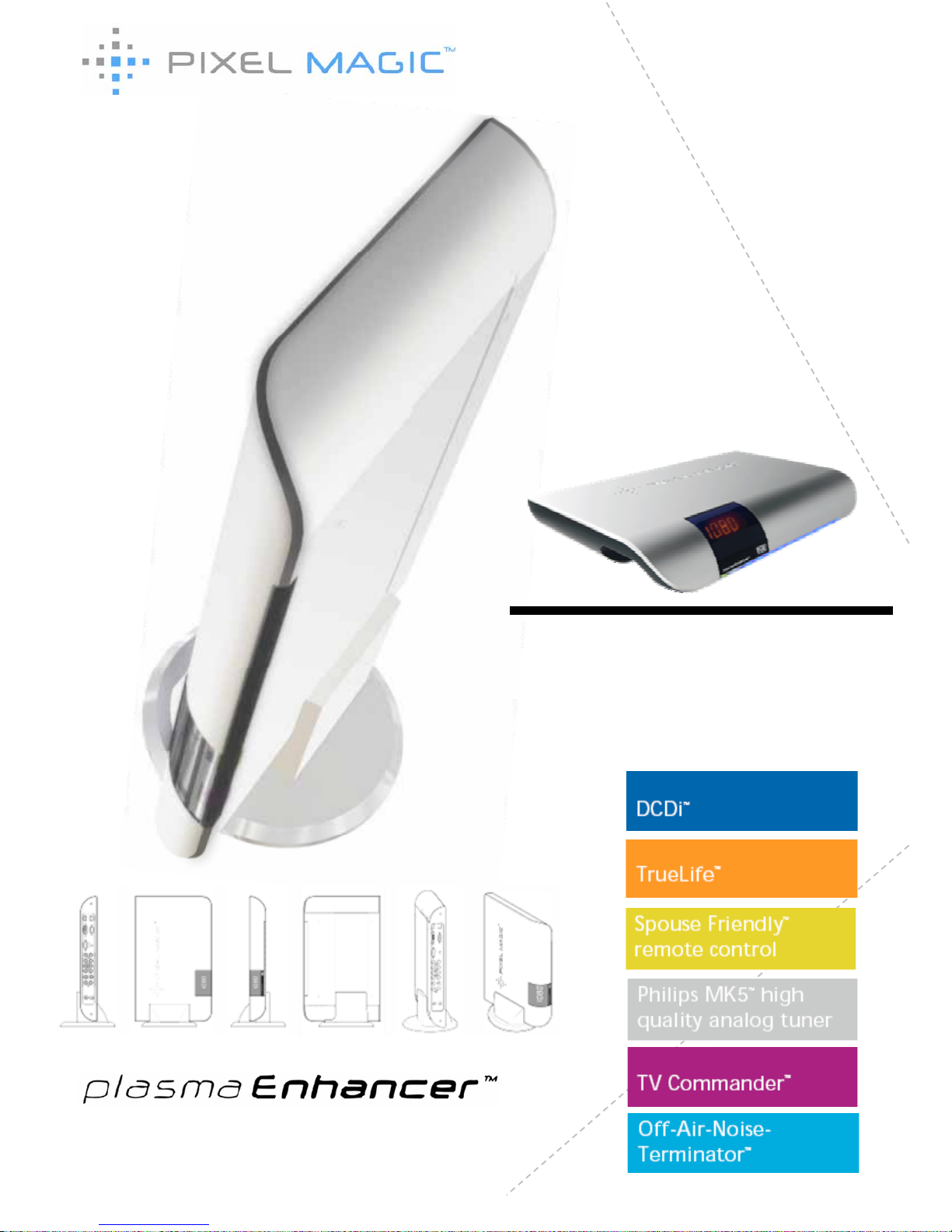
About Plasma Enhancer® PE1000
Plasma Enhancer
is a high performance video processor / scaler specially
designed to enhance video quality of Plasma TVs, LCD TVs, Projectors and
RPTVs.
®
z DCDi
™
z Philips MK5
TM
high quality
analog tuner
z Off-Air-Noise Terminator
™
z Spouse Friendly
™
remote
control
z TV Commander
™
z TrueLife
™
Special Features include:
Special Features include:
Plasma Enhancer
comprises cutting-edge digital video transmission,
processing, scaling and format conversion technologies to deliver
unprecedented high quality video in home theaters.
®
Major technologies including Genesis Microchip’s Emmy award winning DCDi
and TrueLife
are employed to provide impressive de-interlaced processing
and outstanding picture quality. Not only that, Plasma Enhancer
is equipped
with the new Philips 5
generation high quality analog TV tuner MK5 .
Boasting a best-in-class noise figure of less than 5dB throughout the frequency
range, and with improved selectivity, Plasma Enhancer
offers crystal clear
analog TV reception quality.
™
™
®
th ™
®
Video Sources Display Devices
Page 7

5
Overview
Installation and Setup Overview
To install and set up your Plasma Enhancer
PE1000, you can follow our
installation guidelines in this manual. The basic 5 key steps include:
®
1 Display Device Connection: Connect your Plasma Enhancer® to your
display device(s) i.e. Plasma TV, LCD TV with reference to section 2,
Hardware Installation. An On-Screen Display (OSD) menu will be
shown on your display device for your setup.
2 AV Devices Connection: Connect your AV device(s) i.e. DVD Player,
TV cable box to your Plasma Enhancer
®
with reference to section 2,
Hardware Installation.
3 TV Setup: Connect a TV cable or antenna to your Plasma Enhancer
®
with reference to section 2, Hardware Installation and section 3, Basic
System Setup.
4 Plasma Enhancer Configuration: Configure your Plasma Enhancer
®
with reference to section 3, Basic System Setup, and section 4,
Advanced Setup.
5 Registration: Register your Plasma Enhancer
®
at
www.pixelmagicsystems.com to enjoy official warranty, technical
support, and software update from Pixel Magic Systems Ltd.
!!Caution!!
Ensure ALL devices are switched OFF before connecting your audio and
video systems to your Plasma Enhancer
®
Refer to this product manual as and when required for detailed connection and
set up instructions, in addition to our corresponding safety precautions.
Page 8

Familiarizing with Plasma Enhancer® PE1000
Overview
Plasma Enhancer PE1000 Front and Side Panels
®
1
2
3
4
6
5
Front Panel Features
1 Power indicator LED
Green - running mode
Red - standby mode
2 IR indicator LED
Red - Receiving signal from remote control
3 Film indicator LED
Blue - Film mode enabled
4 4-Digit LED display
Display current status of the system
5 AV3: video audio input
S-Video / Composite video with stereo audio input
6
Plasma Enhancer
®
vertical stand
For placing your Plasma Enhancer® vertically
Page 9

7
Overview
Familiarizing with Plasma Enhancer® PE1000
Plasma Enhancer PE1000 Rear Panel
®
4
2 1
3
6
7
8
5
9
Rear Panel Features
1 Power supply cable
entry
Connect with supplied transformer to your Plasma
Enhancer
®
VIDEO / AUDIO INPUTS
2 RF In
Antenna / 75-ohm coaxial input for analog TV tuner:
European (PAL & SECAM) or NTSC
3 AV1: video audio input
Component / S-Video / Composite with stereo audio
4 AV2: video audio input
S-Video with stereo audio
VIDEO / AUDIO OUTPUTS
5 DVI Out
DVI-D digital video out
6 Analog Out
Analog video out via DB15 connector – The DB15 analog
output can also be used as component (YPbPr) video
outputs (via optional adaptor)
7 Audio Out
Stereo audio out
OTHER CONNECTIVITY
8 IR Emitter
Infrared output jack to connect to an external infrared
transmitter (not included)
9 USB, RS232 & RJ45
RS232: For integration of Plasma Enhancer® into home
theatre control systems
USB & RJ45: Reserved for future application
Page 10

Remote Controls
Overview
Full Feature Remote Control
Two remote controls are supplied with your Plasma Enhancer . One is a full
feature remote, another is a smaller and easy-to-use Spouse Friendly™
Remote Control specially designed for your family members.
®
Full Feature Remote Control Features
1 Power ON & OFF
buttons
Press ON to switch on your Plasma Enhancer® & press OFF to
switch to standby mode.
Note: There will be a few seconds delay if switching immediately
between ON and OFF.
2 TV ON/OFF button
Switching your display device ON & OFF.
Note: Only applicable when you have programmed the TV
ON/OFF button to the Plasma Enhancer
®
with a remote module
connected to the back of the device.
3 AV SEL button
Switch between the available video inputs of your display device.
Note: Only applicable when you have programmed the AV SEL
button to the Plasma Enhancer® with a remote module connected
to the back of the device.
4 MUTE button
Mute and restore Plasma Enhancer® audio output
5 0 – 9 buttons
Select and switch to a TV channel using 0-9 buttons
6 -/-- button
Switch between 1-digit & 2-digit TV channel number
7 CH+ / CH- buttons
Scan up and down through channels
8 VOL+ / VOL- buttons
Adjust audio volume (sound system from audio out)
9 AUDIO button
Select multi-channel TV sound (NICAM) options: stereo, dual
(main / sub channel) and mono
10 MENU / OK button
Press MENU to call up OSD menu; OK to select item or confirm
setting
11 ESC button
Exit and go back up one menu level
12 Aspect Ratio
buttons
Directly switch to common aspect ratio settings including 4:3, 16:9,
Natural NLS and 16:9 Letter Box
13 Picture adjustment
buttons
Direct access to Picture adjustment options, including BRIghtness,
CONtrast, COLor and SHArpness
14 RECALL PROFILE
button
Recall a stored user profile
15 INFO button
Display current INFOrmation & status of Plasma Enhancer® on
4-digit LED
16 AUTO / VIDEO buttons
Select AUTO or VIDEO deinterlacing methods
17 Input Select
buttons
Directly select active video source including SDI, AV2, YPbPr1,
TV, VIDEO 1, VIDEO3, S-VIDEO1, S-VIDEO3, HDMI1, HDM2, and
VGA
Note: not all labeled inputs are available on Plasma Enhancer®.
18 PASS
Note: Not applicable
to this model
Applicable to HDMI1, HDMI2, and VGA
Passthrough ON: no processing on input video
Passthrough OFF: processing applied to input video
5
14
18
8
12
15
17
16
13
7
10
9 6
1 3 2
4
11
Note: Insert batteries to
remote control before using
Page 11

9
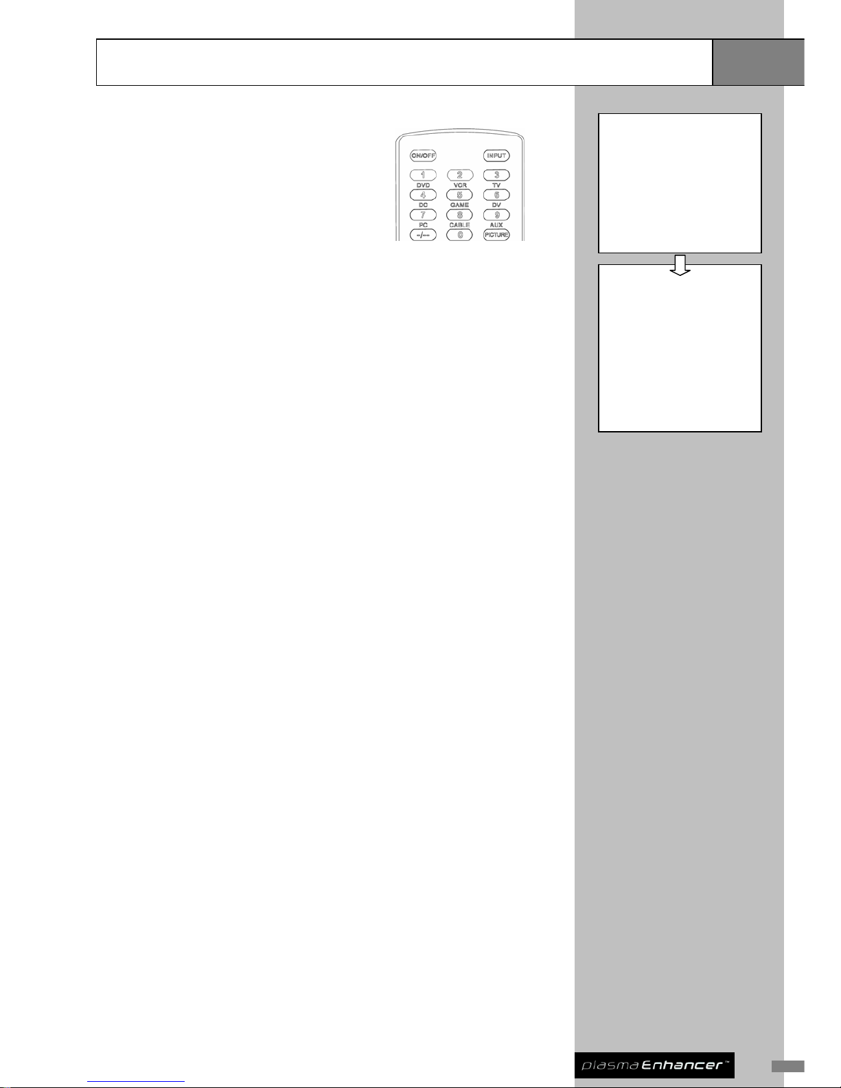
Spouse Friendly Remote Control
™
The Spouse Friendly™ remote control provides a simple and user-friendly
interface for you and your family members to control and navigate the common
functions of your home theatre device(s). From now on, members of your family
can operate a Plasma Enhancer
as easily as operating a TV.
®
The Spouse Friendly
™ remote also allows direct source selection without first
calling up the OSD menu. See section 4, Input Select setup for the initial
configuration for this function.
Spouse Friendly® Remote Control Features
1 ON/OFF button Press ON to switch on your Plasma Enhancer® & press OFF to
switch it to standby mode.
Note: There will be a few seconds delay if switching immediately
between ON and OFF.
2 INPUT button Select from different video input sources.
E.g. Press <INPUT> followed by <1> for DVD input. The DVD
stands for user defined input source on spouse remote function.
3 0 – 9 buttons /
Input Select buttons
Select and switch to a TV channel using 0-9 buttons
4 -/-- button Switch between 1-digit & 2-digit TV channel number
5 PICTURE button Directly call up Picture adjustment menu
6 Aspect Ratio
buttons
Directly switch to 4:3, 16:9, Natural NLS aspect ratio
7
CH+ / CH- buttons
Scan up and down through channels
8
VOL+ / VOL- buttons
Adjust audio volume (same as item 17)
9 MENU button Call up and exit OSD setup menu
10 ENTER button Select item or confirm setting
11 ESC button Exit and go back up one menu level
12 INFO button Display current INFOrmation & status of Plasma Enhancer on
4-digit LED
13 AUDIO button Select multi-channel TV sound (NICAM) options: stereo, dual, &
mono
14 PASS
Note: Not applicable
to this model
Applicable to HDMI1, HDMI2, and VGA
Passthrough ON: no processing on input video
Passthrough OFF: processing applied to input video
15 MUTE Mute and restore Plasma Enhancer® audio output
TV Commander (only applicable when you have programmed the buttons to the Plasma
Enhancer and a remote module is connected to the back of the device)
16 ON/OFF button Switch ON & OFF your display device
17
VOL+ / VOL- buttons
Adjust display device audio volume
18 AV SEL button Switch between the available video inputs of your display device.
Remote Controls
7
Overview
8
9
1
3
2
4
6
5
11
13
12
10
16
14
17
18
15
Note: Insert batteries to the
remote control before use
Page 12
Hardware Installation
Installation
Compatible Equipment
Plasma Enhancer is a high performance video processor and scaler designed
to process TV and video signals from your AV device(s) and transmits the
improved signals to your display device(s).
®
Plasma Enhancer
PE1000 is compatible with:
®
Display Devices:
Analog or digital display device(s) capable of accepting input in the
form of:
z Digital video via DVI-D
z Analog RGBHV or YPbPr (Component Video) via DB15 VGA
connector
AV Devices:
AV source device(s) capable of outputting:
z Component (YPbPr)
z S-Video
z Composite Video
z Antenna for analog TV
Page 13
11
Power Connection
Connect your Plasma Enhancer to a power point using the transformer
provided.
®
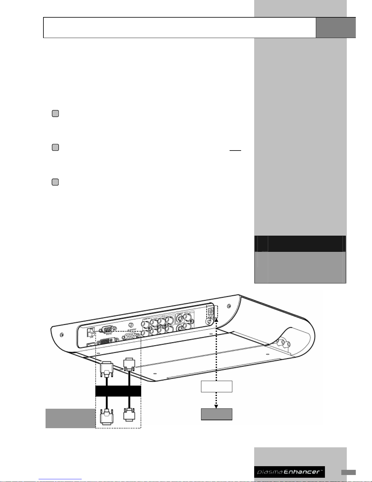
Display Device Connection
1 Preparation: Make sure your display device has either digital DVI-D
or analog VGA (DB15 ) terminals. Prep are the correspondi ng cable for
connection (use high quality cables for optimum picture quality).
2 Connection: Ensure your display device(s) are powered
OFF;
connect your Plasma Enhancer
®
to your display device(s) with
appropriate terminals and cables.
3 Verification: Switch ON both of your Plasma Enhancer
®
and display
device(s); select the input on your display device that corresponds
with the Plasma Enhancer
®
connection. Ensure the On-Screen
Display (OSD) menu of your Plasma Enhancer
®
is displayed properly.
For best result, select the digital connection (DVI-D) of your display device(s)
when both digital (DVI-D) and analog (VGA) terminals are available. Generally,
digital terminal provides better processing and less interference over short/long
distance while the analog terminal cannot offer su ch result.
V
ideo Out
Plasma TV / LCD
TV / Projector /
RPTV
Transformer
Power Point
DVI
Deciding which output terminal
to use for your display
device(s): (Best quality first)
1 DVI-D
2 Analog video out via DB15
connector – The DB15 analog output
can also be used as a Component
(YPbPr) Video output
Installation
Hardware Installation
Page 14

Hardware Installation
Installation
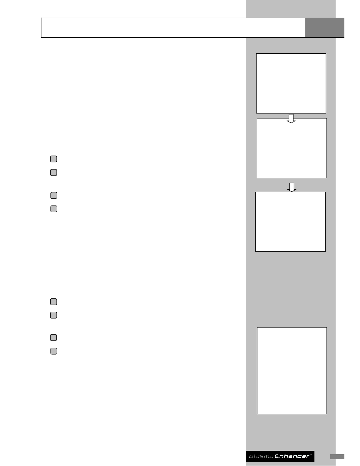
AV Device Connection
Plasma Enhancer embraces a comprehensive set of input terminals that allow
you to connect to a wide range of video devices.
®
Follow the below steps to install:
1 Preparation: List all AV devices that you wish to connect to Plasma
Enhancer
®
for outputting processed video.
2 Allocation: Decide which input terminals of your Plasma Enhancer
®
to use for your AV device(s), and set aside the high quality terminals
to this source(s) i.e. DVD player with Component video output should
be connected to the Component terminal of AV1. Make sure all
required cables are available.
3 Connection: Ensure all devices are powered
OFF; connect the AV
device(s) to your Plasma Enhancer
®
with the appropriate terminals
and cables.
4 Setup: Switch ON your Plasma Enhancer
®
, AV device(s), and display
device(s). Set up your Plasma Enhancer
®
according to the next
section, Basic System Setup.
Deciding which video input to
use for your AV device(s): (Best
quality first)
1 AV 1: Component x 1, S-Video x 1,
Composite x 1 with stereo audio x 1
2 AV 2: S-Video input x 1 with stereo
audio x 1
3 AV 3 on side panel: S-Video x 1,
Composite x 1 with stereo audio x 1
(this is designed for convenient
connection to portable AV devices
such as DV recorder)
Tips: It is recommended that you
choose the interlaced output from
your AV devices, instead of
progressive (e.g. 480i instead of
480p). This leaves the conversion
from interlaced video to
progressive video to be performed
by Plasma Enhanc er
®
, which has
sophisticated processing
dedicated to this task.
Optional AV Am plifier Connection
Antenna Connection
1 Ensure all devices are powered OFF; connect the VHF/UHF to your
Plasma Enhancer
®
with an antenna cable.
2 Switch ON your Plasma Enhancer
®
and set up TV channels
according to section 3, TV Setup.
Page 15

13
Hardware Installation
Installation
Alternative AV Receiver / Processor Connection
Depending on the quality and available input switching you may find it simpler
connecting all AV sources directly to your AV receiver and use the monitor
outputs as the input feed into the Plasma Enhancer
. This allows a greater
number of source components to be connected.
®
1 Preparation: Make all required audio and video connections between
source components and AV receiver. Use the best connection for
each source i.e. Component Video for the DVD player etc. If your
amplifier does not provide a component video input, connect your
DVD player directly to the Plasma Enhancer
®
.
2 Allocation & Connection: Ensure all devices are powered OFF; if
source components are connected via a mixture of: Composite V ideo,
S-Video & Component Video connections, feed all corresponding
Monitor output connections into the required inputs of the Plasma
Enhancer
®
.
3 Setup: Switch ON your Plasma Enhancer
®
, AV device(s) and display
device(s). Setup your Plasma Enhancer
®
according to the next
section, Basic System Setup.
Tips: If you connect the monitor outputs of your AV Receiver to the Plasma
Enhancer
, ensure any available video signal conversion within the AV
receiver itself is switched off. The sophisticated processing and scaling
within the Plasma Enhancer
is dedicated to this task.
®
®
Page 16

Hardware Installation
Installation
For extended
flexibility you may
consider connecting
your Plasma
Enhancer
®
to the
Monitor Outputs of
your AV
Receiver/Processor.
DVD Player
Antenna
Sound System
VCR
Game Console /
DV Recorder
-
A
V1: Component / S-Video /
Composite
AV3: Component /
S-Video / Composite
Audio Out Connection
1 Ensure all devices are powered OFF; connect your Plasma
Enhancer
®
with a stereo audio cable to your sound system.
2 Switch ON both your Plasma Enhancer
®
and sound system and set
up your Plasma Enhancer
®
according to section 4, Audio Map ping.
Note:
Registration will just take a couple
of minutes. You will need your
serial number, so please make a
note of it prior to registration.
Product Registration
To enjoy 12-month warranty, you must register your Plasma Enhancer online
at www.pixelmagicsystems.com
®
Page 17

15
Basic Setup
Basic System Setup
SETUP
→ IMAGE SETUP
DISPLAY SETUP
TV SETUP
SYSTEM SETUP
↑↓: SELECTION
ENTER: CONFIRM ESC: CANCEL
Image Setup (IMAG)
Image Setup is used to set the overall images from your AV devices to your
Plasma Enhancer
. You can select your desired video input, adjust picture
quality etc. The basic setup will be introduced and illustrated here. The
advanced settings and configuration will be demonstrated in the next section.
®
IMAGE SETUP
→ INPUT SELECT ↑
PICTURE
ASPECT RATIO
DEINTERLACER
OVERSCAN
Y/C DELAY
NOISE REDUCER ↓
↑↓: SELECTION
ENTER: CONFIRM ESC: CANCEL
INPUT SELECT
→ YPBPR 1
S-VIDEO 1
S-VIDEO 2
S-VIDEO 3
COMPOSITE 1
COMPOSITE 3
TV
↑↓: SELECTION
ENTER: CONFIRM ESC: CANCEL
OR
ASPECT RATIO
→ 4:3
16:9
FULL SCREEN
16:9 LETTER BOX
2.35:1
NATURAL NLS
↑↓: SELECTION
ENTER: CONFIRM ESC: CANCEL
Input Select (INPU)
This allows you to select the active video source.
1 Press MENU button of your remote control to call up OSD menu.
2 From the SETUP page, use ↑ and ↓ buttons to highlight IMAGE
SETUP, press ENTER button to continue.
3 Choose INPUT SELECT, press ENTER button to continue.
4 Choose the video input terminal that you want to display by using ↑
and ↓ button, and then press ENTER button to confirm.
Tips: You may use the Input
Select button of your remote
controls to select the active
video source directly.
Aspect Ratio (AR)
This is to establish the ASPECT RATIO (AR) of the active video source.
Different AR setting can b e saved for indi vidual video input source and you m ay
required to modify this for the same source (i.e. DVD titles may have different
AR settings; you may check this from the DVD packaging accordingly).
5 Press MENU button of your remote control to invoke OSD menu.
6 Choose IMAGE SETUP, press ENTER button to continue.
7 Choose ASPECT RATIO, press ENTER button to continue.
8 Choose the suitable aspect ratio setting for the active video source by
using ↑ and ↓ buttons then press ENTER button to confirm.
Page 18

Basic System Setup
Basic Setup
Display Setup (DISP)
DISPLAY SETUP
→ RESOLUTION
ASPECT RATIO
↑↓: SELECTION
ENTER: CONFIRM ESC: CANCEL
RESOLUTION
→ 480p ↑
540p
576p
720p
1080i
1080p
640x480 ↓
↑↓: SELECTION
ENTER: CONFIRM ESC: CANCEL
Format of Resolution:
Resolution Format shown
on the LED
480p 480p
540p 540p
576p 576p
720p 720p
1080i 108I
1080p 108P
640 x 480 VGA
800 x 600 SVGA
848 x 480 PL01
852 x 480 PL02
856 x 480 PL03
1024 x 576 PL04
1024 x 768 XGA
1024 x 1024 ALIS PL05
1280 x 720 SXGA
1280 x 768 PL06
1280 x 1024 PL07
1360 x 768 PL08
1360 x 1024 PL09
1366 x 768 PL10
1368 x 768 PL11
1400 x 788 PL12
1400 x 1050 PL13
1920 x 1080 PL14
SETUP
IMAGE SETUP
→ DISPLAY SETUP
TV SETUP
SYSTEM SETUP
↑↓: SELECTION
ENTER: CONFIRM ESC: CANCEL
This setting is of fundamental importance. This will ensure both the OSD menu
and video output of your Plasma Enhancer
are displayed correctly on your
display device(s).
®
Consult your dealer or the display device manual to establish the correct
resolution and aspect ratio settings.
Setting Resolution (RESO)
Resolution refers to the number of columns and rows of pixels your display
device has (for example 1280 x 720).
1 Press MENU button of your remote control to call up OSD menu.
2 From the SETUP page, use ↑ and ↓ buttons to highlight DISPLAY
SETUP, press ENTER button to continue.
3 Choose RESOLUTION, press ENTER button to continue.
4 Choose the resolution of your display device from the list and press
ENTER button to confirm.
Tips: Always check the native resolution of your display device
for best quality.
Setting Aspect Ratio (AR)
AR refers to the ratio of width to height of your display device. For example, if
your display is 16:9 LCD TV, AR of it is 16:9.
5 Press MENU button of your remote control to call up OSD menu.
6 From the SETUP page, use ↑ and ↓ buttons to highlight DISPLAY
SETUP, press ENTER button to continue.
7 Select ASPECT RATIO, press ENTER button to continue.
8 Typically, the AR of your display has been set correctly as shown in
the OSD. Otherwise, you may choose the AR your display device(s)
from the list, and press ENTER button to confirm.
Page 19
17
Basic System Setup
Basic Setup
TV Setup (TV)
SETUP
IMAGE SETUP
DISPLAY SETUP
→ TV SETUP
SYSTEM SETUP
↑↓: SELECTION
ENTER: CONFIRM ESC: CANCEL
Plasma Enhancer is equipped with the latest Philips 5 generation high quality
analog TV tuner MK5™. This offers crystal cl ear analog TV reception quality.
® th
Tuner Setup (TUNE)
The Tuner Setup is operated for searching and creating a list of receivable TV
channels automatically. When setting up TV channels at first time, select
SEARCH ALL BAND to auto scan all receivable TV channels. (Refer to Tips on
the left below)
TV SETUP
→ CHANNEL DETAILS
TUNER SETUP
PROFILE SETUP
↑↓: SELECTION
ENTER: CONFIRM ESC: CANCEL
1 Press MENU button of your remote control to invoke OSD menu.
2 From the SETUP page, use ↑ and ↓ buttons to highlight TV SETUP,
press ENTER button to continue.
TUNER SETUP
→ SOUND SYSTEM: I
TUNER GAIN: 2
SEARCH VHF LOW BAND
SEARCH VHF HIGH BAND
SEARCH UHF
SEARCH ALL BAND
↑↓: SELECTION
ENTER: CONFIRM ESC: CANCEL
3 Choose TUNER SETUP, press ENTER button to continue.
4 Set the TV channels following the instructions shown on screen.
Tuner Gain
Turner gain can be employed in poor reception areas to boost the overall TV
signal.
Channel Details (CHAD)
Use Channel Details to fine tune, shift channels, and d elete surplus channels.
5 Press MENU button of your remote control to invoke OSD menu.
6 From the SETUP page, use ↑ and ↓ buttons to highlight TV SETUP,
press ENTER button to continue.
Tips:
Tuning setup may take longer if
you are doubt with the bandwidth
you should tune from. If you are
familiar with the bandwidth, you
could select to tune directly from:
SEARCH VHFLOW BAND
SEARCH VHFHIGH BAND
SEARCH UHF
If you are not sure, select
SEARCH ALL BAND.
7 Choose CHANNEL DETAILS, press ENTER button to continue.
8 You can fine tune TV channels, move TV channels, and delete
unwanted TV channels.
Profile Setup (PROS)
The profile setting can be utilized to share or separate current video profiles
(aspect ratio, deinterlacer, picture, noise reducer and etc) between channels.
Page 20

Basic System Setup
Basic Setup
Sound Mode
There are numerous sound mode applied to different countries, namely I, D/K,
M, and B/G. For Hong Kong, I is the sound mode that is being used. You may
check with your sound systems user manual or consult your AV retailer for this
information.
System Setup (SYS)
System Setup is used for detailed configuration of your Plasma Enhancer . You
can configure and setup the Spouse Friendly™ Remote Control, video sources
of AV1, audio channels an d audio mapping, TV commander™ and etc.
®
Additional information of SYSTEM SETUP is available in section 4.
Page 21
19
Image Setup
Advanced
Setup
INPUT SELECT
→ SDI ↑
HDMI 1
HDMI 2
VGA
VGA YPBPR
COMPONENT 1
S-VIDEO 1
S-VIDEO 3
COMPOSITE 1
COMPOSITE 3
SCART
TV ↓
↑↓: SELECTION
ENTER: CONFIRM ESC: CANCEL
INPUT SELECT
→ SDI ↑
HDMI 1
HDMI 2
VGA
VGA YPBPR
COMPONENT 1
S-VIDEO 1
S-VIDEO 3
COMPOSITE 1
COMPOSITE 3
SCART
TV ↓
↑↓: SELECTION
ENTER: CONFIRM ESC: CANCEL
Input Select (INPU)
SETUP
→ IMAGE SETUP
DISPLAY SETUP
TV SETUP
SYSTEM SETUP
↑↓: SELECTION
ENTER: CONFIRM ESC: CANCEL
You need to configure and maneuver the active
video source(s) at this menu once, then you will
be able utilize the simple input select button
from your remote controls to navigate the input
source. Simply use the ↓ and ↑ to select and
setup, and press ENTER to confirm your
setting.
IMAGE SETUP
→ INPUT SELECT ↑
PICTURE
ASPECT RATIO
DEINTERLACER
OVERSCAN
Y/C DELAY
NOISE REDUCER
TRUELIFE
NLS CONFIG
POSITION
PROFILE ↓
↑↓: SELECTION
ENTER: CONFIRM ESC: CANCEL
PICTURE
→ BRIGHTNESS ↑
CONTRAST
COLOR
SHARPNESS
R OFFSET
G OFFSET
B OFFSET
R GAIN
G GAIN
B GAIN ↓
↑↓: SELECTION
ENTER: CONFIRM ESC: CANCEL
Picture (PICT)
This menu allows you to alter the appearance
of the video being displayed. An extensi v e
choice of parameters is available. Offset and
Gain are advanced settings and should be
used with care. They allow you to individually
adjust the gain (relative warmth of the color),
and the offset (the amount of black in the color
of the primary Red, Green, and Blue colors.
A
→ 4:3
16:9
FULL SCREEN
16:9 LETTE
2.35:1
↑↓: SELECTION
ASPECT RATIO
→ 4:3
16:9
FULL SCREEN
16:9 LETTER BOX
2.35:1
NATURAL NLS
↑↓: SELECTION
ENTER: CONFIRM ESC: CANCEL
SPECT RATIO
R BOX
NATURAL NLS
ENTER: CONFIRM ESC: CANCEL
Aspect Ratio (AR)
AR is the ratio of image width to image height.
Common motion-picture ratios are 16:9 or 4:3.
LCD s and Plasma screens are usually 16:9.
Always check the DVD titles/disc for a suitable
AR.
DEINTERLACER
→ AUTO
VIDEO
2:2 EVEN
2:2 ODD
NTSC30
↑↓: SELECTION
ENTER: CONFIRM ESC: CANCEL
Deinterlacer (DEIN)
Deinterlacing is the complex process that
converts a traditional interlaced video source
into the progressive scan format required by
modern high definition displays. A wide range of
deinterlacing choice such as AUTO, VIDEO, 2:2
EVEN, 2:2 ODD and NTSC 30 are available.
OVERSCAN
→ OFF ↑
1%
2%
3%
4%
5%
6%
7%
8%
9% ↓
↑↓: SELECTION
ENTER: CONFIRM ESC: CANCEL
Overscan (OVER)
Depending on the video signal, noose
artifacts can occasionally be visible at the
extreme edges of an image. Overscan will
enlarge an image slightly allowing between
0-9% of the original image to be cropped
whilst still remaining image size and quality.
Page 22

Advanced
Setup
Image Setup
Y/C Delay (YCDL)
Y/C DELAY
→ -4 ↑
-3
-2
-1
0
1
2
3 ↓
↑↓: SELECTION
ENTER: CONFIRM ESC: CANCEL
Y/C is abbreviation for luminance / chrominance.
Color and details are kept separate, thus
preventing composite video artifacts. Normally,
Y/C delay is encountered when you see the
color of the image has shifted. If you encounter
this problem, you can adjust the nearby value to
eliminate it.
Noise Reducer (NOIS)
NOISE REDUCER
→ OFF
LOW
MID
HIGH
SUPER
↑↓: SELECTION
ENTER: CONFIRM ESC: CANCEL
Noise Reducer is used to improve video
quality by reducing video noise of off-air
materials, i.e. TV signals produce noises.
Noise reducer can remove the surplus noise.
Choose the one that you feel comfortable.
TRUELIFE options (all with range 0-100)
Detail Eff: sets level of Horizontal Detail
enhancement
Detail Thd: sets threshold point for
introduction of Horizontal Detail enhancement
Luma Edge Eff: sets level of Horizontal Edge
Luma enhancement
Luma Edge Thd: sets threshold point for
introduction of Horizontal Edge Luma
enhancement
Chroma Edge Eff: sets level of Horizontal
Edge Chroma enhancement
Chroma Edge Thd: sets threshold point for
introduction of Horizontal Edge Chroma
enhancement
V Luma Edge Eff: sets level of Vertical
Details enhancement
V Luma Edge Thd: sets threshold point for
introduction of Vertical Detail enhancement
Note: Whilst the SUPER level is very effective at
reducing video noise you may also notice some
finer detailing is also reduced.
TRUELIFE
→ DETAIL EFF ↑
DETAIL THS
LUMA EDG EFF
LUMA EDG THS
CHROMA EDG EFF
CHROMA EDG THS
V LUMA EDG EFF
V LUMA EDG THS ↓
↑↓: SELECTION
ENTER: CONFIRM ESC: CANCEL
TrueLife™ (TRUE)
TrueLife™ uses non-linear algorithms to
enhance; image detail, color and improve
depth perception by sharpening large edges.
This is achieved with no visual artifacts or
distortion.
NLS Config (NLSC)
NLS CONFIG
→ CENTER SHAPE
CROP TO FIT
↑↓: SELECTION
ENTER: CONFIRM ESC: CANCEL
NLS Configuration:
CENTER SHAPE option allows less
horizontal stretching at image center and
more stretching at both sides.
CROP TO FIT option crops top and bottom
part of an image to reduce horizontal
stretching.
NLS Config (Non-Linear Stretching) is used to fill
a full 16:9 screen with a 4:3 image while
minimizing the widening effect on the image.
Position (POS)
This setting allows the displayed image to be
moved to perfectly fit the display device. This
function is of particular use when watching
2.35:1 movies with the subtitles displayed on an
invisible area.
PROFILE
→ RECALL PROFILE
STORE PROFILE
↑↓: SELECTION
ENTER: CONFIRM ESC: CANCEL
Profile (PROF)
Profile allows you to store and recall up to 9
image profiles including all features reference
above.
Page 23
21
Advanced
Setup
System Setup
SETUP
IMAGE SETUP
DISPLAY SETUP
TV SETUP
→ SYSTEM SETUP
↑↓: SELECTION
ENTER: CONFIRM ESC: CANCEL
SYSTEM SETUP
→ LANGUAGE ↑
SPOUSE REMOTE
AUDIO MAPPING
AV1 CONFIG
ANALOG OUTPUT
AUDIO CHANNEL
INFORMATION
TV COMMANDER
SHOW ADVANCED OPTION
FACTORY SETTING ↓
↑↓: SELECTION
ENTER: CONFIRM ESC: CANCEL
Spouse Friendly™ Remote (SREM)
Spouse Friendly™ Remote can be use d to
allocate the AV input terminals to the input
select buttons of the remote itself. Press
<MENU> to call up OSD for setup.
Audio Mapping (AUDI)
This function is used to map appropriate audio out terminal to different video
sources.
AV1 Config (AVCO)
The AV1 Config is used to configure AV1 video terminal as YPbPr (Compo nent
Video) or RGBS.
Analog Output (ANAO)
Analog Output is used to configure VGA (ANALOG OUT) terminal as RGBHV
or YPbPr (Component Video).
Audio Channel (AUCH)
Audio Channel is used to select audio channel of the video source for audio
output. You can use this for NICAM channel selection when viewing TV.
Information (INFO)
This menu will display a complete information page on screen, info such as
firmware version, input source, aspect ratio, resolution, deinterlacer mode,
brightness, contrast, color and sharpness.
Page 24

System Setup
Advanced
Setup
TV Commander™ (TVCM) (Optional)
TV Commander™ is used for your Plasma Enhancer to learn the common
infrared remote control signals of your TV (TV on/off, volume up/down, and AV
selection). You need to configure this before you can control your TV from your
Plasma Enhancer
remote controls.
®
®
(Note: a wired Infrared transmitter is required to be installed at the back of your Plasma
Enhancer
to perform this function)
®
Show Advanced Option (ADOP)
Show Advanced Option is used to configure other settings whi ch are not shown
on the default menu. Select this mode (ON) when you wish to configure your
own advanced settings.
Factory Setting (FACT)
Factory Setting is used when you want to reset your Plasma Enhancer to the
default setting.
®
Page 25

23
Important
Information
Troubleshooting
LED is not displayed properly (including power)
z Check that the unit is connected to a working mains supply, and that it is
switched on.
No picture is displayed at your display device
z Ensure both Plasma Enhancer
®
and the display device is switched ON.
z It may take up to 30 seconds for Plasma Enhancer
®
to complete its
initialization process before the video can be displayed.
z Ensure your display device is properly connected to Plasma Enhancer
®
and correct video input is selected from your display device.
z Press MENU button from the remote control and check whether the OSD
can be correctly shown on your display device.
z Check whether correct resolution is set for your display device. Refer to
section 2, DISPLAY SETUP for more information.
z Ensure your AV device is properly connected to Plasma Enhancer
®
and
correct video input has been selected from Plasma Enhancer
®
.
z Ensure the source video is of correct format.
Picture is displayed but is unstable
z Check cabling, particularly that the cable providing video sync is
connected correctly.
Picture appears to be stretched
z Ensure that the aspect ratio of the video source material, aspect ratio of
your display device, and display resolution are all correctly set.
Page 26

Technical Specifications
Important
Information
Audio / Video Inputs
z Antenna input for analog TV tuner x 1: European (PAL & SECAM) or
NTSC versions are available
z A V1: S-V ideo x 1, Component (config urable as RGBS) x 1, Composit e x 1,
with stereo audio x 1
z AV2: S-Video x 1 with stereo audio x 1
z AV3 on front panel: S-Video x 1, Composite x 1, with stereo audio x 1
Audio / Video Outputs
z Digital video: DVI-D x 1
z Analog video: RGBHV or Component (YPbPr)(DB15 connector)
z Stereo audio
Resolutions supported
z 480p, 540p, 576p, 720p, 1080i, 1080p, 640x480, 800x600, 848x480,
852x480, 856x480, 1024x576, 1024x768, 1024x1024 ALiS, 1280x720,
1280x768, 1280x1024, 1360x1024, 1366x768, 1368x768, 1400x788,
1400x1050, 1920x1080;
User-friendly appliance
z On-Screen Display for easy system setup
z Two dif f erent remote control units are included
z One infrared output jack on rear panel to connect to an external infrared
transmitter (not included)
z TV Commander™ (optional)
General
z Dimensions: 344 x 210 x 44 mm / 13.5 x 8.3 x 1.75 inch
z Weight: 2.5 kg / 5.5 lb
z Power Consumption: 16W
z Power Supply: 110 / 220V AC Auto-sensing
Specifications and features subject to change without notice
Page 27

25
Safety Information
Important
Information
Safeguards & Important Safety Instruction
z To reduce the risk of electric shock, do not remove cover (or back) no
user-serviceable parts inside. Refer servicing to qualified service
personnel.
z If the wall plug does not fit into your local power socket, then ask your
electrician to replace your obsolete outlet. Do not modify the wall plug. To
do so will void the warranty and safety feature.
z To ensure maximum performance, please read this manual carefully. Keep
it in a safe place for future reference.
z Install this unit in a cool, dry, clean place – away from windows, heat
sources, and sources of excessive vibration, dust, moisture and cold. A void
sources of humming (transformers, motors). To prevent fire or electrical
shock, do not expose the unit to rain or water.
z Never remove the unit cover. Contact your dealer if an object falls inside
the unit.
z Do not use force on switches, controls or connection wires. When moving
the unit, first disconnect the power plug and the wires connected to other
equipment. Never pull on the wires themselves.
z The openings on the unit cover assure proper ventilation of the unit. If
these openings are obstructed, the temperature inside the unit will rise
rapidly . Th erefore, avoid placin g objects against these openings, and install
the unit in a well-ventilated area to prevent fire and damage.
z Be sure to allow a space of at least 30 cm behind, 20 cm on the both sides
and 10 cm above the top panel of the unit to prevent fire and damage.
z The voltage used must be the same as that specified on this unit. Using this
unit with a higher voltage than specified is dangerous and may result in fire
or other accidents. PIXEL MAGIC SYSTEMS LTD will not be held
responsible for any damage resulting from use of this unit with a voltage
other than specified.
z Digital signals generated by this unit may interfere with other equipment
such as tuners, receivers or TVs. Move this unit farther away from such
equipment if interference is observed.
z Do not attempt to clean the unit with chemical solvents; this might damage
the finish. Use a clean, dry cloth.
z Be sure to read the “TROUBLESHOOTING” section regarding common
operating errors before concluding that the unit is faulty.
z When not planning to use this unit for long periods of time, disconnect the
AC power plug from the wall outlet.
z To prevent lightning damage, disconnect the AC power plug when there is
an electrical storm.
z Grounding or polarization– Precautions should be taken so that the
grounding or polarization of an appliance is not defeated.
z This unit is not disconnected from the AC power source as long as it is
connected to the wall outlet, even if this unit itself is turned off. This state is
called the standby mode. In this mode, this unit is designed to consume a
small amount of power .
Page 28
Support and Warranty Information
Important
Information
Product Support
Plasma Enhancer
is designed to provide you an ever long lasting viewing
pleasure. If for any reason you encounter a problem with your Plasma
Enhancer
, please follow the following:
®
®
z Carefully follow the steps shown in section 5 Troubleshooting; or
z Contact your Plasma Enhancer
®
retailer for advice.
!!Caution: Under NO circumstances should you attempt to open, repair
or modify your Plasma Enhancer
®
unit as this could expose you to
electrical shock, and / or severely damage your Plasma Enhancer
®
.
Product Warranty
Pixel Magic Systems Ltd warrants Plasma Enhancer
for one-year from the
date of purchase to the original purchaser that this product is free from defects
in material and workmanship. If, after inspection, you discover any defects in
material or workmanship, Pixel Magic Systems Ltd will have the option to repair,
or replace the defective Pixel Magic Systems’ product free of charge. This
one-year warranty does not cover damages from normal wear and tear or from
accidental damage, misuse, improper care, alterations and damage caused in
transportation by a common carrier or airline.
®
There are no other warranties expressed or implied, including, but not limited to,
the implied warranties of merchantability and the fitness for a parti cular purpose
beyond the terms of this one-year warranty. The one-year warranty offered by
Pixel Magic Systems Ltd herein may not be modified by any oral
representations made by any employee, agent or representative of Pixel Magic
Systems Ltd.
Repair or replacement as provided under this warranty is the exclusive remedy
of the consumer. Pixel Magic Systems Ltd shall not be liable for any incidental
or consequential damages for breach of any expressed or implied warranty on
this product, except to the extent prohibited by applicable law; any implied
warranty of merchantability or fitness for a particular purpose on this product is
limited in duration to the duration of this warranty . If you need to have your Pixel
Magic Systems’ product repaired or replaced under the conditions of this
one-year warranty, please contact your dealer to make suitable arrangements.
Limitation of Liability (for all customers)
BOTH YOURS AND PIXEL MAGIC SYSTEMS’ LIABILITY SHALL BE LIMITED
TO THE PRICE PAID FOR PRODUCT. IN NO EVENT SHALL EITHER YOU
OR PIXEL MAGIC SYSTEMS LTD BE LIABLE TO THE OTHER FOR ANY
INDIRECT, SPECIAL, INCIDENTAL OR CONSEQUENTIAL DAMAGES
RESULTING FROM PERFORMANCE OR FAILURE TO PERFORM UNDER
THIS AGREEMENT, OR USE OF ANY GOODS OR SERVICE SOLD
PURSUANT HERETO, WHETHER DUE TO A BREACH OF CONTRACT,
BREACH OF WARRANTY, NEGLIGENCE , OR OTHERWISE. NEITHER YOU
NOR PIXEL MAGIC SYSTEMS LTD SHALL HAVE ANY LIABILITY TO THE
OTHER FOR INDIRECT OR PUNITIVE DAMAGES OR FOR ANY CLAIM BY
ANY THIRD PARTY EXCEPT AS EXPRESSLY PROVIDED HEREIN.
Page 29

27
Notes
Page 30

Pixel Magic Systems Ltd
Email: sales@pixelmagicsystems.com
Website: http://www.pixelmagicsystems.com
DCDi by Faroudja and TrueLife™ are registered trademarks of Genesis Microch ip.
®
Off-Air-Noise-Terminator™, Spouse Friendly™, and TV Commander™ are registered
trademarks of Pixel Magic Systems Ltd.
All rights reserved.
 Loading...