

Page 1
Email Support: nzsupport@magictv.com
© 2009 Pixel Magic Systems Ltd. All rights reserved. Magic TV
and Pixel Magic are Trademarks of Pixel Magic Systems Ltd.
MyFreeview|HD is a Registered Trademark of Freeview Ltd. All
other trademarks are properties of their respective owners.
Specifications subject to change without notice.
www.magictv.com
Owner's Guide
Page 2

2 3
1. Read these instructions.
2. Keep these instructions.
3. Heed all warnings.
4. Follow all instructions.
5. Do not use this apparatus near water.
6. Clean only with a dry cloth.
7. Do not block any ventilation openings. Install in accordance
with the manufacturer’s instructions.
8. Do not install near any heat sources such as radiators, heat
registers, stoves, or other apparatus (including amplifiers)
which produce heat.
9. Do not expose this appliance to dripping or splashing water
and no object filled with liquids (such as a vase) should be
placed on this appliance.
10. Do not interfere with the safety aspects of the polarized or
grounding-type plug. A polarized plug has two blades with
one wider than the other. A grounding type plug has two blades
and a third grounding prong. The wide blade or the third prong is
provided for your safety. If the provided plug does not fit into your
outlet, consult an electrician for replacement of the obsolete outlet.
11. Protect the power cord from being walked on or pinched, particularly
at plugs and the point where they exit from the apparatus.
12. Only use attachments/accessories specified by the manufacturer.
13. Unplug this apparatus during lightning storms or when unused for
long periods of time.
14. Refer all servicing to qualified service personnel. Servicing is
required when the apparatus has been damaged in any way, such
as if the power-supply cord or plug has been damaged, liquid has
been spilled, objects have fallen into the apparatus, the apparatus
has been exposed to rain or moisture, does not operate normally,
or has been dropped.
Safety Information
TO REDUCE THE RISK OF FIRE OR ELECTRIC SHOCK, DO NOT EXPOSE THIS PRODUCT TO
RAIN OR MOISTURE.
TO REDUCE THE RISK OF FIRE OR ELECTRIC SHOCK, DO NOT USE THIS PLUG WITH AN
EXTENSION LEAD, RECEPTACLE OR OTHER OUTLET UNLESS THE BLADES CAN BE FULLY
INSERTED TO PREVENT BLADE EXPOSURE.
The lightning flash with arrow-head symbol,
within an equilateral triangle, is intended to
alert the user to the presence of uninsulated
“dangerous voltage” within the product’s
enclosure that may be sufficient magnitude to
constitute a risk of electric hock to persons.
The exclamation point within a triangle is
intended to alert the user to the presence
of important operating and maintenance
(servicing) instructions in the literature
accompanying the product.
Additional Safety Instructions
• To ensure maximum performance, please read this manual carefully.
Keep it in a safe place for future reference
• Install this unit in a cool, dry, clean place - away from windows, heat
sources, sources of excessive vibration, dust, moisture and cold. Avoid
sources of humming (transformers, motors). To prevent fire or electrical
shock, do not expose the unit to rain or water
• Do not force connection wires. When moving the unit, first disconnect
the power plug and the wires connected to other equipment. Never
pull on the wires themselves
• The openings on the unit cover assure proper ventilation of the unit.
If these openings are obstructed, the temperature inside the unit will
rise rapidly. Therefore, avoid placing objects against these openings,
and install the unit in a well-ventilated area to prevent fire and damage
• Be sure to allow a space of at least 30 cm behind, 20 cm on both
sides and 10 cm above the top panel of the unit to prevent fire
and damage
• Digital signals generated by this unit may interfere with other
equipment such as tuners, receivers or TVs. Move this unit further
away from such equipment if interference is observed
• Do not attempt to clean the unit with chemical solvents; this might
damage the finish. Use a clean, dry cloth
• Be sure to read section 10: Troubleshooting regarding common
operating errors before concluding that the unit is faulty
• When planning not to use this unit for long periods of time,
disconnect the AC power plug from the wall outlet
Additional Safety Instructions
• To prevent lightning damage, disconnect the AC power plug when
there is an electrical storm
• Grounding or polarization - Precautions should be taken so that the
grounding or polarization of an appliance is not compromised
• This unit is not disconnected from the AC power source as long as
it is connected to the wall outlet, even if this unit itself is turned off.
This state is called the standby mode. In this mode, this unit is
designed to consume a small amount of power
Page 3

4
Table of Contents
Safety Information 2
Additional Safety Instructions 3
1. Welcome 7
1.1 Package Contents 8
1.2 Basic Definitions9
2. Tour of Magic TV™ 11
2.1 Remote Control 12
2.2 Rear Panel 14
2.3 Front Panel Display 16
3. Cabling 17
3.1 Power and Aerial/Antenna Connections18
3.2 Direct Connection to a TV 19
3.3 Connection Via an AV Receiver 21
3.4 Other Setup Options23
4. Guided Setup 25
4.1 Getting a Picture 26
4.2 Welcome to Magic TV™ Guided Setup 26
5. Viewing Live TV 29
5.1 Simple Operations30
5.2 The Freeview Guide 32
5.3 Aspect Ratio Correction 34
6. Recording and Playback 35
6.1 Basic Magic TV™ Recording Terms36
6.2 Instant Recording36
6.3 Recording from the EPG 37
6.4 Timer Recording37
6.5 Viewing and Amendi
ng Scheduled
Recordings Using the To Do List 38
6.6 Recording Priorities and Conflicts 39
6.7 Browsing Recorded Programmes 39
6.8 Managing Recorded Programmes 41
6.9 Playback of Recorded Programmes 43
6.10 TimeShifting & Pausing Live TV 44
6.11 Editing Recordings 45
6.12 Parental Control 46
7. Magic TV™ Gadgets 47
7.1 News 48
7.2 Weather 48
7.3 HD Camcorder Movies 49
8. Magic TV™ Settings 51
8.1 Info Format 52
8.2 Video 53
8.3 Audio 55
8.4 Recording56
8.5 Playback Setup 57
5
8.6 Channel Setup 57
8.7 Guided Setup 59
8.8 Parental Control 59
8.9 System 59
9. System Operations 61
9.1 Network Setup 62
9.2 Firmware Upgrade 63
10. Troubleshooting 65
10.1 Common Problems66
10.2 Setting the Output Format
from the Front Panel 68
10.3 Rescue Procedure 69
11. Support & Warranty 71
Page 4

6
1
Welcome
1.1 Package Contents 8
1.2 Basic Definitions 9
7
Page 5
1
Welcome
9
Thank you for purchasing Magic TV™. An exciting new world of digital
and high definition television is now at your fingertips.
This Owner’s Guide helps you learn about the correct operation and
features of Magic TV™. Please read it carefully.
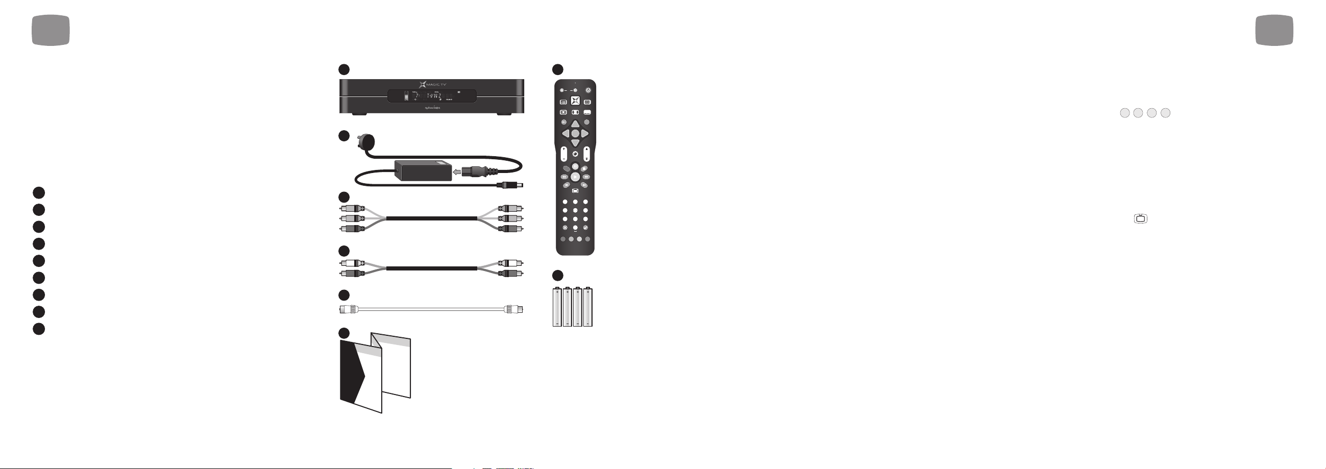
1.1 Package Contents
Before starting, please check the following items were
included in your package:
Magic TV™ HDTV Receiver or Personal Video Recorder
100-240V AC auto-ranging power adapter
Magic TV™ Remote Control
4x AAA batteries for remote control
Component video cable
Stereo audio cable
Aerial/antenna extension cable
Quickstart Guide
This Owner’s Guide
Please contact your Magic TV™ retailer immediately
if any of the above items are missing.
9
8
7
6
5
4
3
2
1
1
Welcome
8
1.2 Basic Definitions
If you are new to Digital Television Broadcasts there are a few terms you
should know:
High Definition (HDTV).
A picture on the TV screen is formed by
a large number of small dots called pixels. The higher the
number of pixels, the better the picture quality will be. The
pictures of conventional analogue TV broadcasting provide a
maximum of 720 (horizontal) x 576 (vertical) pixels. Typically
HDTV broadcasts contain at least 1024 horizontal pixels and
720 vertical pixels, providing superior picture quality over
analogue TV broadcasts. The HDMI and Component video
outputs of Magic TV™ are capable of carrying an HDTV signal.
Standard Definition (SDTV). A picture with only 576 or 480 vertical
pixels is referred to as Standard Definition. The S-Video and Composite
video outputs of Magic TV™ are Standard Definition only.
Digital Terrestrial Television (DTT). Digital TV is a far more efficient
and flexible transmission system than the current analogue system. It
allows broadcasters (TVB and ATV) to offer viewers a range of new and
different services – all through your existing aerial/antenna.
The possible benefits include:
• 'Ghost free' reception
• Widescreen 16:9 pictures
• Standard definition television (SDTV) and HDTV programmes
• High quality audio and surround sound
• Multi-channel programming
• Closed captioning of programmes for the hearing impaired
• Electronic Programme Guides (EPGs)
• On-screen programme guide channel with today's programme
information
• Multi-camera views and enhancements during selected programmes
Interactive Services. Digital TV has the potential to include interactive
programmes, alternative camera angles, selected Internet services, home
shopping, computer games and more. Some services may require an
Internet connection (see section 9.1). When available, you can access
these features by pressing and following the on-screen
instructions.
HDMI (High Definition Multimedia Interface). HDMI is an
uncompressed, all-digital video and audio connection for electronic
devices capable of transmitting High Definition signals. These signals are
usually encrypted using HDCP to prevent unauthorized duplication of
copyrighted material. HDMI is the highest quality video output from
Magic TV™.
Live TV. If you’re watching a program while it’s being broadcast, you’re
watching Live TV. Pressing the button on your remote control will
immediately jump to Live TV from any menu.
Video Output Format. DTT broadcasts can come in a variety of shapes
and sizes. Magic TV™ can cleanly scale the broadcasts to suit your TV.
See section 8.2 for further information.
Multi-channel audio. A surround sound system supporting six discrete
audio channels. These are Left, Center, Right, Rear Left, Rear Right, and
Subwoofer. DTT broadcasters may choose to broadcast some
channels/programmes in multi-channel audio. Use a digital audio
connection (optical, coaxial or HDMI) to an AV receiver in order to hear
all six channels.
Aspect Ratio. A TV’s aspect ratio is the comparison of the screen’s width
to its height. This is typically 4:3 for analogue and standard definition
broadcasts and 16:9 for HD broadcasts.
Aspect Ratio Correction. This is required when the shape of the
broadcast picture and the TV don’t match. The Aspect button on your
remote control lets you quickly change the shape of the broadcast
picture. See section 5.3 for further information.
LIVE
BLUE
YELLOW
GREEN
RED
1
2
5
6
7
8
Start he
3
TV
GUIDE
ASPECT AUDIO SUBTITLE
TEXT
i
OK
VOL
CH
R
LIVE
123
ABC DEF
456
GHI JKL MNO
7809
PQRS TUV WXYZ
CLEAR ENTER
4
AAA
AAA
AAA
AAA
re
Page 6

2
Tour of Magic TV™
2.1 Remote Control 12
2.2 Rear Panel 14
2.3 Front Panel Display 16
11
Firmware Upgrade. From time to time Magic TV™ will receive updates
for the software that controls it. Normally these updates will occur
automatically Over-The-Air (OTA). Firmware update can also be
achieved via USB and over the internet. It’s possible that these updates
will provide features not covered in this guide. Details of new features
will be available at www.magictv.com/nz/support.html. See section 9.2.
1
Welcome
10
Page 7
1312
Programming the Remote Control
Step 1. Place the Magic TV™ Remote Control and the TV remote control
on a flat surface, 3cm apart and with the emitters facing each other.
Step 2. Press and hold both the and buttons for
2 seconds until the LED Indicator flashes slowly.
The Magic TV™ Remote Control is now in "learning mode".
For Samsung, Sony, Sharp, Philips or Pioneer TVs
Press either for Samsung, for Sharp, for Sony, for Philips
For other TVs
Step 3. Press the button you want programmed ( for example).
The LED Indicator will light.
Step 4. Press and hold the Power button on your TV remote control
until the LED Indicator turns off.
Step 5. After 2 seconds the LED Indicator will flash slowly again;
please repeat steps 3 and 4 for each button.
Step 6. When finished, press the button to exit "learning mode".
To reset the buttons to factory defaults, press and hold both the
and the lower corner button for 2 seconds until the LED
Indicator flashes slowly, then press the button.
OK
RED
4
3
2
1
2
Tour of Magic TV™
2
Tour of Magic TV™
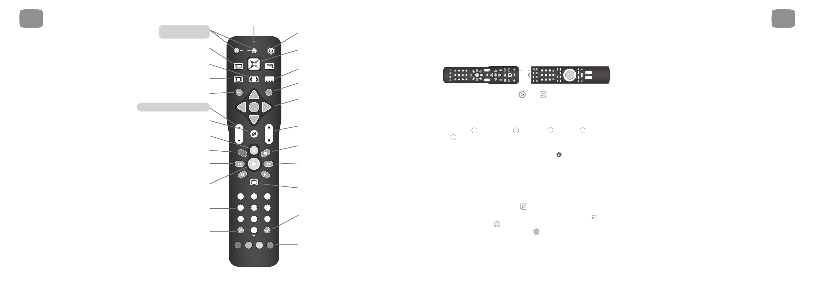
2.1 Remote Control
The Magic TV™ Remote Control is used to
control every aspect of Magic TV™. In order
to make using the remote as easy as possible,
4 of the buttons can be programmed with
commands for your TV.
Inserting the Batteries
• Push in the ridged area of the battery
cover and slide the cover down
• Insert four AAA batteries (supplied) by
matching the + and – marks on the
batteries to the + and – marks in the
battery compartment. Note that two of the
batteries will slide under the casing slightly
• Replace the battery door
If the batteries are working and are inserted
correctly, the LED Indicator will flash when
any button is pressed.
or for Pioneer preset remote control commands. Then go to step 6.
5
Learning buttons
TV Power & TV Input
Electronic Programme
Guide (EPG)
Audio track selection
Aspect Ratio Correction
mode selection
Back
Learning buttons Vol+ & Vol
Mute
Pauses Live TV and
Recorded Programmes
Records the current programme
Rewinds Playback
Resumes Playback
Alphanumeric keys
Cancel or Delete
LED Indicator
Power On/Off
TV
GUIDE
ASPECT AUDIO SUBTITLE
TEXT
i
-
OK
VOL
R
123
456
GHI JKL MNO
7809
PQRS TUV WXYZ
CLEAR ENTER
CH
LIVE
ABC DEF
Magic TV™ button (access
to all menus)
Subtitle language selection
Programme information
Navigation of on-screen
menus. OK during Live TV
will show channel list
Channel Up/Down or
Page Up/Down when
in Menus
Stops Playback and recording
Speeds up Playback.
Press again for faster speed
Live TV. Jumps to Live TV
from any menu
Adds and removes bookmarks
during playback
Contextual navigation including
Interactive Television Services.
Refer to onscreen hints for
exact function
ASPECT AUDIO SUBTITLE
CLEAR ENTER
PQRS TUV WXYZ
GHI JKL MNO
123
456
78
ABC DEF
0
9
VOL
R
LIVE
CH
GUIDE
3cm
TV
OK
TEXT
i
Page 8
2
Tour of Magic TV™
1514
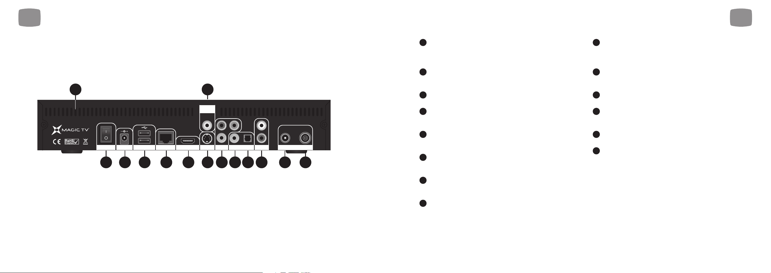
Power On/Off Switch. Turn Magic TV™ on using this switch.
Magic TV™ consumes very little power on Standby. It is therefore
unnecessary to turn Magic TV™ off with this switch during normal
operation
DC Power In. The included 100-240V AC auto-ranging power
adapter should be attached here. Please see “Safety Information”
before proceeding
Ventilation holes. It is important that all the ventilation holes in
Magic TV™ are kept clear, in order for hot air to escape
HDMI. (Connects to a TV, AV receiver or home theatre system.)
HDMI provides a pure digital connection for high definition video
and audio all in one cable
Composite Video. (Connects to a TV, AV receiver, VCR, DVD
recorder or home theatre system.) Composite is the most basic of
video connections and is Standard Definition only
S-Video. (Connects to a TV, AV receiver, VCR, DVD recorder or
home theatre system.) S-Video offers a higher quality signal than
Composite for compatible equipment but is Standard Definition only
Component Video (YPbPr). (Connects to a TV, AV receiver or
home theatre system.) Component provides an excellent quality High
Definition analogue video connection
Coaxial Digital Audio. (Connects to an AV receiver or home
cinema system.) If you are not using the audio over HDMI, then this
connection will provide multi-channel digital audio to your surround
sound system
Optical Digital Audio. (Connects to an AV receiver or home
cinema system.) If you are not using the audio over HDMI, then this
connection will provide multi-channel digital audio to your surround
sound system
Analogue Stereo Audio. (Connects to a TV, VCR or DVD
recorder.) Connect the left/right audio cables (included) for
analogue stereo sound
USB x2. Magic TV™ can be updated with new software via USB.
See section 9.2
Ethernet Network. Use this connection to link Magic TV™
to your home network. This may be needed for some of the
Interactive Services
Antenna In. A coaxial RF cable needs to be connected to this input
to allow Magic TV™ to receive the new DTT signals
Loop Out (Antenna Out). Connect the included Aerial/Antenna
extension cable from this output to another device if you wish to
retain analogue TV reception (on your TV for example)
14
13
12
11
10
9
8
7
6
5
4
3
2
1
2.2 Rear Panel
2
Tour of Magic TV™
3
ON/OFF
Composite
Video
Pb
Pr
Y
12V DC
NetworkUSB HDMI YPbPr
21 657 8 9 1011 12 1314
S-Video HDTV Tuner
Digital Audio
4
L
R
Audio
Loop
Out
Ant.
In
Page 9

1716
3.1 Power and Aerial/Antenna Connections 18
3.2 Direct Connection to a TV 19
3.3 Connection Via an AV Receiver 21
3.4 Other Setup Options 23
2
Tour of Magic TV™
2.3 Front Panel Display
3
Cabling
Output Format Indicator, This display
shows 1080i/p, 720p, 576i/p, 480i/p,
50Hz, 60Hz as chosen in Settings >
Video > Video Output Format
Hard Disk Drive (HDD)
space meter. When the
top (red) segment is lit,
the HDD is full
Recording indicator. Red
circle will light if Magic TV™
is currently recording
Scheduled Recording indicator.
Lights when Magic TV™ has
been set to record a future
Playback Indicator. Lights when a
Recorded Programme is being played
Alpha-numeric Display which can
show TV channel information, OSD
mode and clock (in standby) with
ALL
Loop Play indicator. Lights
during playback when Loop
Play has been chosen
am/pm indicator
HDMI Output Indicator.
Lights when the HDMI
output is active
Online Indicator. Lights if the
network connection is active
Live TV Indicator, Lights solidly
if the Signal Quality on
current channel is good. Off
or flashing if quality is poor
Infra Red receiving
area. Keep
unobstructed and
in sight of the
remote control
HDMI Audio indicator. Lights
when the HDMI output
contains embedded audio
Page 10
1918
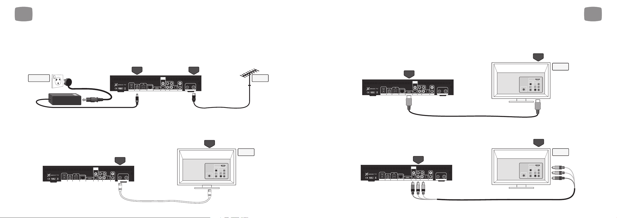
3.2 Direct Connection to a TV
Video + Audio - for HDMI equipped HDTVs
HDMI is the highest quality video output from Magic TV™. It can also carry multi-channel audio, which conveniently reduces cabling.
Simply connect the HDMI output from Magic TV™ directly to one of your TV's HDMI inputs.
Video - for HDTVs without HDMI
In order to get High Definition video from Magic TV™ without HDMI, Component (YPbPr) must be used. Simply connect the Component output
from Magic TV™ directly to one of your TV’s Component inputs. Component doesn't carry audio, so a separate connection is needed. See below.
Television
YPbPr
(component)
YPbPr
(component)
Audio
Video
Antenna
HDMI
INPUTS
S-Video HDTV Tuner
Ant.InLoop
Out
NetworkUSB HDMI YPbPr
Audio
Digital Audio
L
R
Composite
Video
Pb
Pr
Y
12V DCON/OFF
Television
HDMI
Audio
Video
Antenna
HDMI
INPUTS
HDMI
HDMI
HDMI
S-Video HDTV Tuner
Ant.InLoop
Out
NetworkUSB HDMI YPbPr
Audio
Digital Audio
L
R
Composite
Video
Pb
Pr
Y
12V DCON/OFF
3
Cabling
3.1 Power and Aerial/Antenna Connections
Power + Antenna
Insert the power cord into a suitable power outlet and the 12v DC plug into Magic TV™. Leave the power outlet switched off or unplugged until all the
wiring work has been completed. Then connect Magic TV™ to your antenna using the Ant. In connector. A roof-mounted antenna is recommended for
best reception. For information on monitoring your signal quality, see section 8.6.
Optional - Antenna loopthrough
If you want to retain analogue TV reception on your television or on any other devices with a TV tuner (VCR or DVD recorder for example), connect the
included extension cable to the Loop Out connector of Magic TV™ and to the Antenna In on your other device. Many devices can form part of the
antenna loop, by chaining together the Antenna Outs to Antenna Ins on each device.
We recommend using Magic TV™ as the first component on the chain and your television as the last.
Loop
Out
Ant. In
Television
Other device with
a tuner on board
(
VCR or DVD recorder
for example).
OR
Audio
Video
Antenna
HDMI
INPUTS
S-Video HDTV Tuner
Ant.InLoop
Out
NetworkUSB HDMI YPbPr
Audio
Digital Audio
L
R
Composite
Video
Pb
Pr
Y
12V DCON/OFF
12V DC
Ant. In
100v-240v AC
Power Outlet
Aerial/
Antenna
S-Video HDTV Tuner
Ant.InLoop
Out
NetworkUSB HDMI YPbPr
Audio
Digital Audio
L
R
Composite
Video
Pb
Pr
Y
12V DCON/OFF
3
Cabling
Page 11
2120
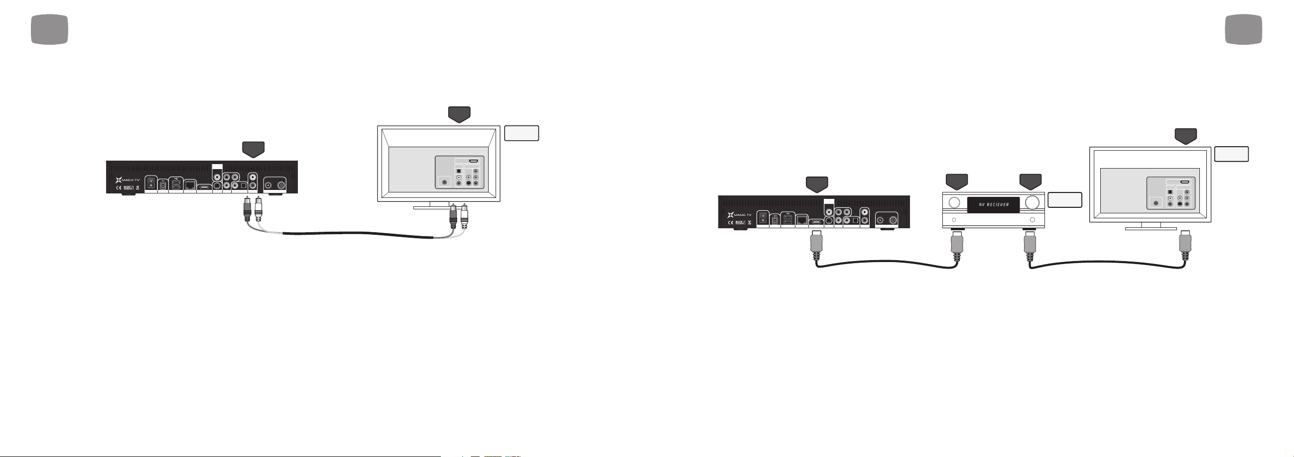
3.3 Connection Via an AV Receiver
Video + Audio - for HDMI equipped receivers and HDTVs
HDMI is the highest quality output from Magic TV™. It can also carry multi-channel audio, which conveniently reduces cabling. Simply connect the HDMI
output from Magic TV™ to one of your receiver's HDMI inputs and connect one of your receiver's HDMI outputs to one of your TV's HDMI inputs.
Television
AV Amp/
Receiver
HDMI
HDMI
HDMI
INPUT
HDMI
OUTPUT
Audio
Video
Antenna
HDMI
INPUTS
HDMI
HDMI
HDMI
HDMI
S-Video HDTV Tuner
Ant.InLoop
Out
NetworkUSB HDMI YPbPr
Audio
Digital Audio
L
R
Composite
Video
Pb
Pr
Y
12V DCON/OFF
3
Cabling
Audio - for HDTVs without HDMI
Not many televisions can accept a digital audio signal, in which case you may be limited to using the Stereo audio outputs of Magic TV™. Simply
connect the Stereo Audio output from Magic TV™ directly to one of your TV's Stereo Audio inputs.
3
Cabling
Analogue
Audio
Television
Analogue
Audio
Composite
Video
Pb
L
Pr
Y
Digital Audio
R
S-Video HDTV Tuner
NetworkUSB HDMI YPbPr
12V DCON/OFF
Ant.InLoop
Out
Audio
INPUTS
Antenna
HDMI
Audio
Video
Page 12
2322
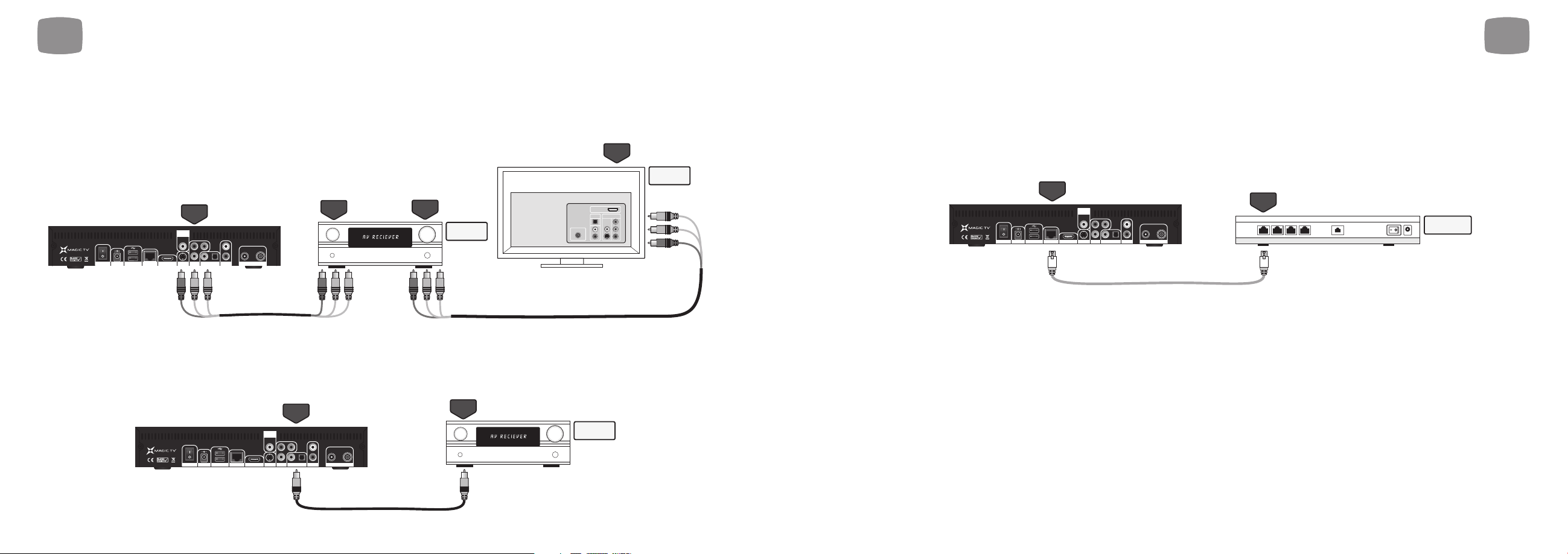
3.4 Other Setup Options
Network connection for Interactive Services
Some of the features present in the new MHEG-5 Interactive Services broadcasts require an internet connection (competition entries, voting, subscribing and
purchasing, for example). You will need to have an existing Ethernet Network present in your home. Simply use a CAT-5 cable to connect the Network port
of Magic TV™ to your network router or hub. See section 9.1 for information on network setup.
Ethernet
Network
Ethernet
Network
Network
Hub/Router
S-Video HDTV Tuner
Ant.InLoop
Out
NetworkUSB HDMI YPbPr
Audio
Digital Audio
L
R
Composite
Video
Pb
Pr
Y
12V DCON/OFF
3
Cabling
3
Cabling
Video - for receivers or HDTVs without HDMI
If your receiver or television don't have HDMI, you can still get a very high quality High Definition image using Component (YPbPr). Simply connect the
YPbPr output from Magic TV™ to one of your receiver's Component or YPbPr inputs and connect one of your receiver's Component or YPbPr
outputs to one of your TV's Component or YPbPr inputs. Component doesn't carry audio, so a separate connection is needed. See below.
Audio - for receivers or HDTVs without HDMI
If your receiver doesn't have HDMI, you need to make a separate audio connection. Magic TV™ has both Coaxial and Optical digital audio outputs.
Use whichever is more convenient. Simply connect one of the Digital Audio outputs from Magic TV™ to one of your receiver's Digital Audio inputs.
AV Amp/
Receiver
Coax or
Optical
Coax or
Optical
in
S-Video HDTV Tuner
Ant.InLoop
Out
NetworkUSB HDMI YPbPr
Audio
Digital Audio
L
R
Composite
Video
Pb
Pr
Y
12V DCON/OFF
YPbPr
(component)
Television
AV Amp/
Receiver
YPbPr
(component)
YPbPr
(component)
in
YPbPr
(component)
out
Audio
Video
Antenna
HDMI
INPUTS
S-Video HDTV Tuner
Ant.InLoop
Out
NetworkUSB HDMI YPbPr
Audio
Digital Audio
L
R
Composite
Video
Pb
Pr
Y
12V DCON/OFF
Page 13

2524
4.1 Getting a Picture 26
4.2 Welcome to Magic TV™ Guided Setup 26
4
Guided Setup
Page 14
2726
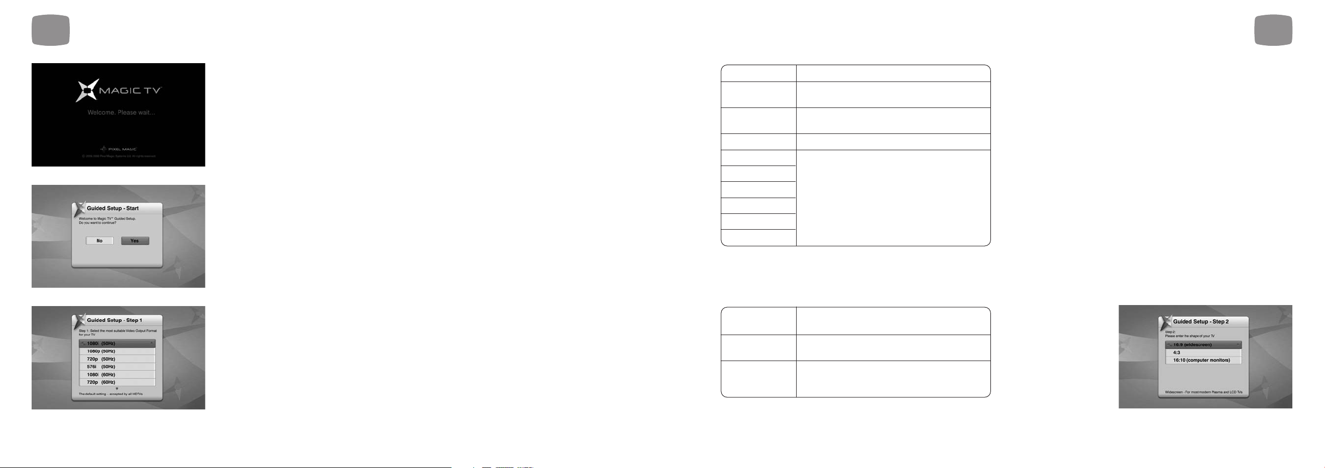
Step 2: Please select the Aspect Ratio of your TV
16:9 Choose this if your TV is widescreen
(widescreen) * (most modern Plasma and LCD TVs)
4:3 Choose this if you have a traditionally
shaped TV
16:10 Choose this if you are using a widescreen
(computer computer monitor as your display
monitors)
1080i (50Hz) * The default setting – accepted by all HDTVs
1080p (50Hz) A good choice if your TV accepts a 1080p
HDMI input
720p (50Hz) A good choice if your ‘HD Ready’ TV has 720 or
768 lines of resolution
576i (50Hz) Use only if your TV is Standard Definition
576p (50Hz)
1080i (60Hz)
1080p (60Hz) Use these only under special circumstances
720p (60Hz)
– see
section 8.2
480i (60Hz)
480p (60Hz)
4
Guided Setup
4.1 Getting a Picture
• Turn Magic TV™ on
• Turn your TV on
• Change input on your TV to the one used by Magic TV™
• If this is the first time Magic TV™ has been switched on, the Guided Setup will be shown
• The default video output is 1080i (50Hz). If you can't see the Welcome Screen, please check that
your TV supports this format. If not, please read section 10.2 to change the Video Output Format
using the front panel display
4.2 Welcome to Magic TV™ Guided Setup
Do you want to continue?
Choose yes to be taken through Magic TV™ setup.
Step 1: Please select the best Video Output Format for your TV
Choose the most appropriate option from the list.
To ensure that you can always see a picture, Magic TV™ will automatically revert back to the
previous format after 15 seconds if you haven’t responded to the on-screen prompt.
4
Guided Setup
*
=
default setting
*
=
default setting
Page 15

4
Guided Setup
28 29
5.1 Simple Operations 30
5.2 Freeview Guide 32
5.3 Aspect Ratio Correction 34
Step 3:
Scan for channels automatically
This step will scan through all the available frequencies looking for channels. Once complete,
Magic TV™ will display a list of the channels found.
Guided setup is now complete
You can now view Live TV, view the Electronic Programme Guide or take a look at some
of the other setup options.
If you wish to return to ‘Guided Setup’ at any time, it can be found under Settings Guided Setup.
5
Viewing Live TV
Page 16

3130
5
Viewing Live TV
The Info Banner - current program information
The info banner will show every time the channel is changed; however you can also
view it while you’re watching a programme by pressing .
i
5
Viewing Live TV
CH
5.1 Simple Operations
Changing Channels
You can change channels in four different ways.
During Live TV, change channel Up/Down quickly.
In menus scroll Page Up/Down.
Enter the channel number
directly if known.
Use the built-in Electronic Programme
Guide (EPG) to browse and select a channel.
During Live TV press OK to show a Channel List.
Use Up/Down arrows to select a channel and
OK to confirm.
Interactive Services
During some programmes, Interactive Services
will be available.
Navigate the Interactive screens and menus using the
arrow/OK buttons and also the coloured buttons according to
onscreen instructions.
Remote Control Shortcuts
If you want to record during Live TV,
press R to see a menu of options.
Pauses Live TV and starts recording the current programme
so that you can catch up later (see section 6.10).
Jumps to the Recorded Programmes List.
Cycles through the available Audio languages.
Cycles through the available Subtitle languages.
Magic TV™ Menu
Press the at any time to access the Main Menu. From here you can
access all of the Magic TV™ features and options.
i
OK
OK
R
AUDIO
SUBTITLE
GUIDE
123
456
7809
RED GREEN
YELLOW
BLUE
Programme name
Programme start
and finish times
Channel number
and name
Programme
description
Title of the next
programme on on
this channel
Icons to show information about the current programme
Programme is High Definition
Contains Dolby Surround Sound
Multiple audio tracks are available
Subtitles are available
Programme is being recorded
Playback of a Recorded Programme
Currently TimeShifting (see section 6.10)
Current time
Press these remote
control buttons for extra
functions during Live TV
Page 17

3332
5
Viewing Live TV
EPG Listings
When you press the button on your remote, you'll see 'loading...'.
This tells you that the Freeview Guide is being downloaded to your
digital receiver. You will then see a screen like the one below.
Press yellow on your remote to go to the previous day's listings
or blue to go to the next day's listings for the current channel.
You can loop through 8 days this way.
Press on a highlighted programme and, if it is currently on, you will
be tuned in to that highlighted channel and programme.
Press on your remote to exit the Freeview Guide and return to the
programme you were watching.
OK
BLUE
YELLOW
GUIDE
5.2 The Freeview Guide
The Freeview Guide enables you to view 8 days of programme listings on all Freeview channels. It also contains a Now/Next screen that shows what is
on now and next for each channel. When new channels are added to the Freeview service they will automatically appear on the Freeview Guide.
5
Viewing Live TV
Channel logo and date
for the listings shown
below
Button hints. Press
these buttons for
extra features
Programme times
and names.
Scroll through the
programmes
Synopsis for the
currently highlighted
programme
Parental Rating and
Captioning information
Channel number of
current listings
A mini-screen showing
the programme you
were previously
watching with channel
name and current time
Scroll through
channels
Press the channel number
button (e.g. for TV3) to
move directly to that
channel’s listings page
3
What’s on Now/Next
Press when viewing the EPG Listings to display the 'What's On
Now/Next' page.
Press on your remote to watch the channel and programme you've
highlighted.
Press on your remote to exit the EPG and return to the programme
you were watching.
Press again to return to the current day's listings page for the
highlighted channel.
GUIDE
OK
GUIDE
Channel numbers
and name
Scroll through the
programmes
Press the channel
number button (e.g.
for TV3) to jump that
channel to the top
Button hints. Press
these buttons for
extra features
3
Current time and date
Programmes
currently showing
and up next including
start times
Page 18

3534
5
Viewing Live TV
5.3 Aspect Ratio
Correction
Freeview HD channels are always
broadcast in 16:9 widescreen format.
If the programme is 4:3, then black
bars will be included in the broadcasted
image on the sides of the programme.
Aspect Ratio Correction can be used to
remove these black bars and stretch the
image in different ways to achieve the
desired result.
Use the button of the Magic TV™
Remote Control to cycle through the
available modes.
ASPECT
Original broadcast
(and also how the image will look if
'Full' is selected)
Aspect Ratio
Correction
mode used
Full
The broadcast fills the screen
WideZoom
Magic TV™ removes the sides and
non-linearly stretches the image
keeping the centre of the screen
undistorted
Zoom 1
Magic TV™ zooms in on the
centre of the screen - retaining the
original shape
Zoom 2
Magic TV™ removes the sides and
evenly stretches the image to fill
the screen
Letterbox
/Pillarbox
If a programme appears stretched
in ‘Full’ mode, this mode could
correct it by adding black bars to
the sides or top and bottom
Result
on 16:9 TV
6
6.1 Basic Magic TV™ Recording Terms 36
6.2 Instant Recording 36
6.3 Recording from the EPG 37
6.4 Timer Recording 37
6.5 Viewing and amending Scheduled
Recordings using the To Do List 38
6.6 Recording Priorities and Conflicts 39
6.7 Browsing Recorded Programmes 39
6.8 Managing Recorded Programmes 41
6.9 Playback of Recorded
Programmes 43
6.10 TimeShifting & Pausing Live TV 44
6.11 Editing Recordings 45
6.12 Parental Control 46
Recording and Playback
Page 19

6.3 Recording from the EPG
The easiest way to record future programmes is to find them on the
Freeview Guide. Simply highlight your chosen programme and press
on your remote control.
Series recordings
If the programme is part of a series you will be presented with the option
to either record this single episode or record the whole series.
This useful service allows Magic TV™ to record and store every episode
of a series without you having to remember.
Press yellow to record the whole series or blue to record just this
episode.
Series recordings will be shown in the Magic TV™ menus with a [S]
before the programme name.
One-off recordings have [R] before their name.
6.4 Timer Recording
By navigating to Main Menu Recording Timer Recording, you can
set Magic TV™ to record a particular channel at a particular time.
You can select the Channel, Date, Time and Length of recording
6
Recording and Playback
37
There are many easy ways to record programmes with Magic TV™.
You can record the programme you’re watching instantly, choose a
programme to record from the EPG, set a traditional timer or record
at the same time every day.
6.1 Basic Magic TV™ Recording
Terms
Instant Recording. Recording the programme currently being viewed.
Scheduled Recording. Recording a future programme.
Series Recordings. Recordings which have been made with the "Record
the whole series" option (see section 6.3). These are shown on the EPG
as an [S] instead of an [R] for single recordings."
Timer Recording. Manually setting a time for Magic TV™ to record.
To Do List. This is where you can view and amend Scheduled
Recording tasks.
TimeShifting. You are in TimeShifting mode when you are watching a
delayed version of Live TV. For example when you pause Live TV
because of an interruption, you are now in TimeShifting Mode (see
section 6.10).
Keep. This term refers to how long Recorded Programmes will be kept
before being deleted.
Trash. Once Recorded Programmes are deleted, they are placed in
Trash. When a programme is in Trash, it will no longer appear in any
other list, until it is either restored, overwritten or permanently deleted
(see section 6.8)
Conflict. When 2 or more scheduled recordings overlap.
Disk Space. Magic TV™ uses a Hard Disk Drive to store Recorded
Programmes. When this disk is full, no more recordings can be made.
See section 6.8 on how to manage recordings so that you can free up
disk space and keep important recordings.
Remaining Recording Time: This is displayed on many screens and is
labelled in hours for HD (High Definition) and SD (Standard Definition)
programmes. All programmes broadcast in HD will be recorded in HD.
6.2 Instant Recording
Recording the programme you’re watching is easy - just press on
your remote control. Magic TV™ will start recording the current
programme instantly.
The current programme now behaves like a Recorded Programme and
you can control it as shown in section 6.9.
R
6
Recording and Playback
36
RED
YELLOW
BLUE
Page 20

6.6 Recording Priorities and
Conflicts
Magic TV™ will constantly check to see if any new recordings or changes
to a Scheduled Recording cause an overlap.
MTV3600TD reduces the likelihood of conflicts by allowing programmes
to be viewed and recorded on 2 different frequencies simultaneously.
If Magic TV™ detects an overlap or conflict when making or amending a
Scheduled Recording, a message will appear asking you to set the
priority for that programme.
Unless the programmes start and stop times match exactly, Magic TV™
will still record some of the lower priority programme.
6.7 Browsing Recorded
Programmes
A full list of the recorded programmes can be found under Main Menu
Recorded Programmes.
The Recorded Programmes list can also be accessed by pressing
while watching Live TV.
As the number of recorded programmes can run into the hundreds,
Magic TV™ has a number of ways to help find them fast.
Browsing Categories can be:
Filter View (Main): Use these to quickly narrow your search by
reducing the number of recordings shown in the right-hand list.
Higher This programme will be recorded instead of lower
priority Scheduled Recordings
Lower If a Higher priority scheduled recording conflicts with this
one, the other will be recorded
Cancel This will cancel the new recording/adjustment
6
Recording and Playback
39
6.5 Viewing and Amending
Scheduled Recordings Using
the To Do List.
The To Do List can be found under Main Menu Recording To Do
List. This list allows you to browse and amend all future Scheduled
Recordings.
Once a task has been completed, it will be removed from this list.
[R] before the programme name means that only one episode
has been recorded.
[S] means that this recording is part of a Series Recording
(see section 6.3)
If you highlight a Scheduled Recording and press you will be
presented with the following options:
Tasks can also be cancelled by pressing the button on your remote
control and answering yes to the confirmation.
CLEAR
Cancel this
Scheduled Recording
Extend/Delay You can set the Start Time earlier or later
Start Time than the EPG start time by none, 1, 2, 3, 5,
10 or 15 minutes.
Note: This value will be
used instead of the global value set in Main
Menu Settings Recording
Extend/Delay Start Time for this particular
programme
Extend Stop Time You can set the Stop Time later than the
EPG stop time by none, 1, 2, 3, 5, 10, 15
or 30 minutes, or 1, 2 or 3 hours.
Note: This value will be used instead of the
global value set in Main Menu Settings
Recording Extend Stop Time for this
particular programme
Move recorded Once the programme has been recorded
programme to folder it will be moved to the selected folder
Re-arrange Recording See the next section
Priority
Exit
OK
6
Recording and Playback
38
Page 21

6
Recording and Playback
41
Folder View: Organise your recordings into folders to help you find
them. See section 6.8 about managing folder contents. A programme
can only appear in one folder at once.
Series Recordings: By pressing yellow you can view a list of
programme names in the left hand menu. Once a name is selected,
a list of individual episodes will be shown on the right.
Trash: Here you can view programmes that have been deleted.
See section 6.8 for further details.
Once you’ve entered a list, you can still swap between the Browsing
Categories by using the coloured buttons:
Programme list
On the right of the screen is a list of programmes. Once your highlight
bar is in the right-hand column, the list can be sorted in many ways by
pressing one of the coloured buttons. Pressing the button again will
toggle between an ascending or descending list.
Sort by date
Sort by programme length
Sort by name
Sort by channel number
GREEN
YELLOW
BLUE
RED
Filter View (Main)
Folder View
Repeat Recordings
GREEN
YELLOW
RED
YELLOW
Not in Folder Performance Finance
My Favourites Arts Food
Series Music User 1
Sport Culture User 2
Movie Education User 3
Concert Entertainment User 4
Travel Documentary
Children News
All programmes
Not yet viewed
Trash
6
Recording and Playback
40
You can also perform these operations on multiple files at once.
Simply press on all the files you wish to select and then press .
Press on a highlighted recording and Magic TV™ will begin playing
the programme (from the last stop point if one exists).
You can play multiple recordings without interruption by selecting
multiple recordings (by pressing ) and then pressing .
Recordings will play in the order they were selected.
Press on a highlighted recording to delete the file.
Depending on the Parental Control settings in section 6.12, you may
be asked to enter your PIN before playback will start. Files can be
‘undeleted’ later (see next section).
6.8 Managing Recorded
Programmes
Organising programmes into folders
In order to find recorded programmes faster, Magic TV™ has a folder
system where you can move recorded programmes into folders with
meaningful names. This can be done from either the To Do List or
Recorded Programme List.
After pressing on a highlighted programme in either list, you can
select ‘Move to Folder’. The available folders are as follows:
To view the contents of the folders, simply go to the Recorded
Programme List and press .
GREEN
Not in Folder Performance Finance
My Favourites Arts Food
Series Music User 1
Sport Culture User 2
Movie Education User 3
Concert Entertainment User 4
Travel Documentary
Children News
OK
CLEAR
ENTEROKENTER
Resume Play The programme will begin playing
from the point it was last stopped at
Play from the beginning The programme will begin playing
from the beginning of the recording
Remove all Bookmarks Deletes all the previously set
bookmarks and cut-marks from the
recording (if any). See
sections 6.9
and 6.11
Delete this programme You will be asked to confirm that you
want to move this recording to Trash
Keep programme for You will be asked how long you want
to keep this recording for.
Select from various lengths of time,
and also ‘Forever’. See section 6.8
Move to folder This recording will be viewable under
the selected folder
Press on a highlighted recording and you will be given the
following options:
OK
Page 22
Deleting and undeleting files
When browsing your recorded programmes, you can delete them by
pressing and choosing “Delete this programme” or by pressing
Magic TV™ then marks these files as ‘deleted’ and removes them from
the listings. The HDD space is now available for further recordings.
However, it is still possible to recover deleted files provided that they
have not been overwritten.
In the main Recorded Programme List, there is a Filter called ‘Trash’.
When a programme is highlighted and is pressed, you will have
the following options:
Pressing on a programme in Trash will permanently remove
it after confirmation.
Keeping Files
By default, Magic TV™ will keep all files until the Hard Disk Drive is full.
At this time, if another recording is made, Magic TV™ may delete the
oldest programme in order to make room.
This default setting of ‘Until Disk Full’ can be changed in Main Menu
Settings Recording Keep Recorded Programme For, and options
include numbers of weeks, months, 1 year and ‘Forever’.
Keep settings can also be set for individual recordings by highlighting
them in the Recorded Programmes list, pressing and choosing the
required time period.
'Forever' will not overwrite recordings unless they have been manually
deleted. If you keep programmes ‘Forever’, it is possible that Magic TV™
will not be able to make a new recording if the disk is full. However,
the front panel display and many of the menus contain the disk space
information so that you can be aware of a potential problem.
After the keep period has passed, Magic TV™ will move the file to Trash
and the space will be made available for new recordings.
OK
CLEAR
Undelete this This will restore the programme and it will
programme behave exactly like it did before deletion
Permanently remove Once this has been selected, the file cannot
this programme be restored
Exit
OK
CLEAR
OK
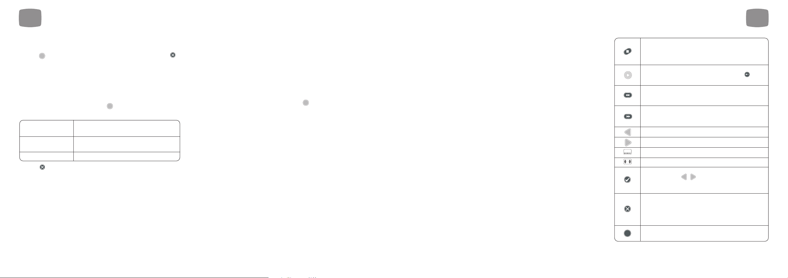
6.9 Playback of Recorded
Programmes
Once a recording has been selected from the Recorded Programmes List,
playback will begin. During playback you get all the features you would
expect from a video recorder such as pause, fast forward and rewind,
but there are some other features too.
The table opposite shows the functions of remote control buttons during
playback:
6
Recording and Playback
43
6
Recording and Playback
42
Will stop playback and return to the Recorded
Programme List. Magic TV™ will remember this point
and you can choose to resume playback from this
point later
If already playing, this button can be used to
display the Timebar for 30 seconds. Pressing
will hide it again
Rewind – the programme will rewind at double the
normal speed. Press the button again to increase
speed of rewind to 4x, 8x, 16x and 32x
Fast Forward – the programme will move forward at
double the normal speed. Press the button again to
increase speed of Fast Forward to 4x, 8x, 16x and 32x
Skips backwards to the previous bookmark
Skips forward to the next bookmark
Cycles through the available subtitles (if any)
Cycles through the available audio tracks (if any)
Creates a bookmark at the current playback time.
You can use the buttons to skip between
bookmarks. Pressing the button again within 10
seconds of a bookmark will remove it
Creates a cut-mark at the current playback time.
Magic TV™ will now miss out the section between a
cut-mark and bookmark pair during playback (see
section 6.11). Pressing the button again within 10
seconds of a cut-mark will remove it
Shows an Info Banner about the
recorded programme
SUBTITLE
AUDIO
ENTER
CLEAR
i
Page 23
45
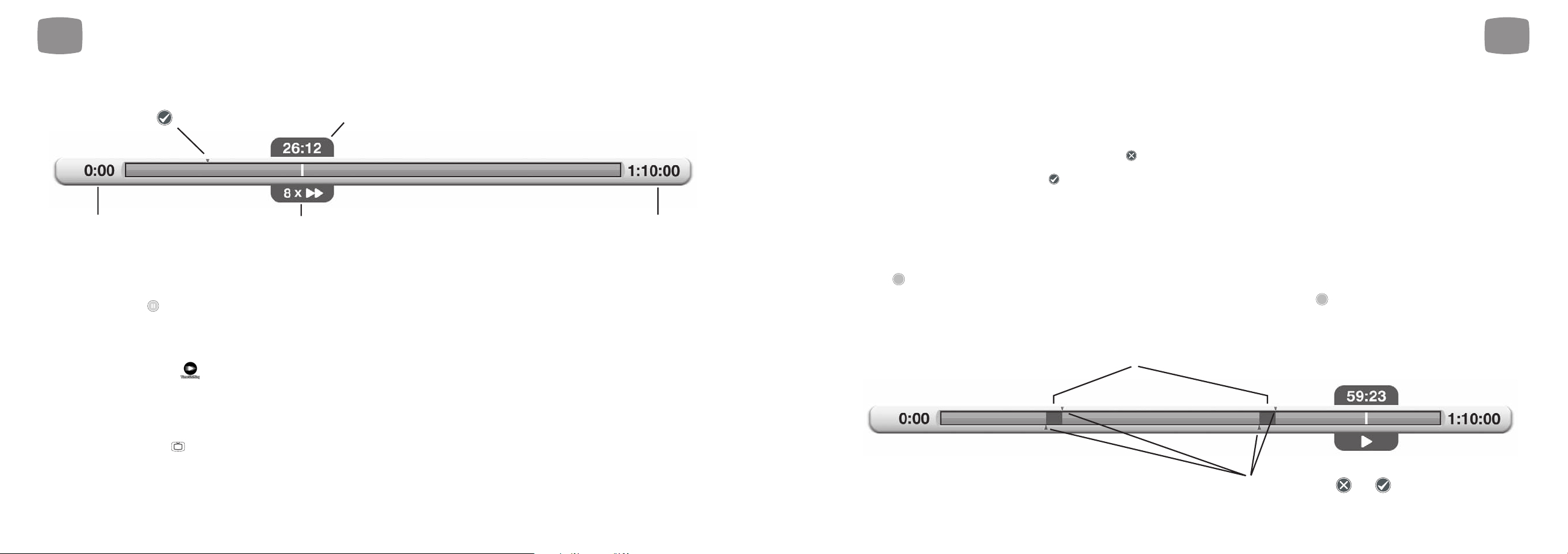
The Playback Timebar
6.10 TimeShifting & Pausing Live TV
If your Live TV viewing gets interrupted and you don’t want to miss
anything, you can press to freeze the action.
It will remain paused and immediately begin recording the current
programme. You can press play at any time to resume viewing from
where you left off.
The programme now displays a and behaves like a Recorded
Programme (see above) and you can rewind, fast forward, pause and
skip in exactly the same way within the segment of the programme that
has been recorded.
To return to the live broadcast, you can either fast forward/skip to the
end of the recording or press at any time.
LIVE
6
Recording and Playback
44
6
Recording and Playback
6.11 Editing Recordings
Magic TV™ allow you to edit recordings by choosing which parts of recordings are shown and which are hidden.
The original recording is always kept intact and edit points can be removed at any time.
To edit out a section (a commercial break for example), carry out the following steps:
1. During Playback, at the start of the section to be cut press to add a ‘cut-mark’ to the recording
2. At the end of the section to be cut, press
3. Magic TV™ will now miss out the section between these marks during future playback.
Any section to be missed will be shown on the Timebar as transparent
4. Multiple sections can be edited out by inserting another cut-mark and bookmark pair
Edits can be removed by deleting a cut-mark or bookmark, or by highlighting the programme on the Recorded Programme List,
pressing and selecting “Remove all Bookmarks” from the menu.
Edits can be made permanent by highlighting the programme on the Recorded Programme List, pressing and selecting “Edit and Move” from the
menu. From the same menu, you can also select “Edit and Copy” which will create a duplicate file. The original will be intact and the copy will have the
edited sections permanently removed.
OK
OK
ENTER
CLEAR
Bookmarks (made and removed
by pressing the button)
Beginning of the recording Length of the recorded programme
Status. In this case the programme is being
fast forwarded at 8x normal speed.
Current playback time from
beginning of recording
Transparent areas between cut-marks are edited out and wont play
Cut-mark/bookmark pairs inserted by pressing and
Page 24

47
6.12 Parental Control
The Magic TV™ Parental Control system works in tandem with the
Freeview Parental Ratings to enable you to effectively control what your
family views.
Every programme on Freeview NZ includes a rating in accordance with
the Codes of Practice formulated by New Zealand broadcasters and the
government-appointed Broadcasting Standards Authority.
Programme ratings can be viewed in the white area of the Freeview
Guide (see section 5.2).
You can control which rating level of programmes can be viewed freely
and which require the input of your PIN.
Simply go to Settings Parental Control Level Setting and select the
level you want blocked. Levels above this will also be blocked.
The default PIN is 0000 and you can change this in Settings Parental
Control Change PIN Code. Please make a note of your number as the
only way to reset the PIN is to do a full factory reset of Magic TV™, which
will lose your personal setup options.
Unrated
G General Programmes which exclude material likely to be
unsuitable for children. Programmes may not necessarily
be designed for child viewers but must not contain
material likely to alarm or distress them.
PGR Parental Guidance Recommended Programmes
containing material more suited for mature audiences but
not necessarily unsuitable for child viewers when subject
to the guidance of a parent or an adult.
AO Adults Only Programmes containing adult themes and
directed primarily at mature audiences.
6
Recording and Playback
46
7
Magic TV™ Gadgets
7.1 News 48
7.2 Weather 48
7.3 HD Camcorder Movies 49
Page 25

7
Magic TV™ Gadgets
49
7
Magic TV™ Gadgets
48
For live News and Weather updates, an Internet connection and local
network is required. Please connect Magic TV™ to your broadband router
or network (connection instructions are in sections 3.4 and 9.1). For other
network and Internet related support issues, please consult your Internet
Service Provider (ISP).
7.1 News
Magic TV™ can keep you updated on local and global news stories
by displaying News bulletins from popular and trusted sources.
Simply choose your preferred news supplier from the supplied list
and browse an up-to-date list of news stories.
When viewing a news story, you can quickly jump to the next or previous
story by pressing . Pressing will return you to the previous menu.
If a news item is long, press to scroll the text and reveal more.
*News and Weather information is obtained from the Internet. Pixel Magic does not guarantee
the accuracy or reliability of any information.
7.2 Weather
Magic TV™ can also display New Zealand weather information.
Simply choose your preferred region and browse the latest updates.
If a weather bulletin is long, press to scroll the text and reveal more.
*News and Weather information is obtained from the Internet. Pixel Magic does not guarantee
the accuracy or reliability of any information.
7.3 HD Camcorder Movies
Magic TV™ can browse, copy and play AVCHD and HDV camcorder
files from many of the latest HD camcorders. When you select this option,
Magic TV™ will automatically search all folders named “AVCHD” or
“VIDEO” for movies with the .m2t (HDV) or .mts/m2ts (AVCHD)
extensions.
The files found are presented in alphabetical order of folder name, then
file name.
Colour coding
Pressing on a movie name will reveal the following options:
Playback functions and options are very similar to normal recorded
programme playback. You can also select multiple movies by using the
button and then by pressing .
Multiple movies will play in the order they were selected.
Due to the different ways in which camcorder manufacturers encode
video, there may be some minor playback issues. Sometimes these ‘problem’
files can be fixed with third party computer applications. Pixel Magic cannot
guarantee playback quality of non-broadcast videos.
Play Plays the highlighted movie(s)
Play All Plays all the movies in the list
Copy to Copies the Camcorder movie onto the System
System HDD Hard Disk Drive for convenient future playback
OK
Black File is located on the internal HDD
OK
ENTER
Page 26

5150
8.1 Info Format 52
8.2 Video 53
8.3 Audio 55
8.4 Recording 56
8.5 Playback Setup 57
8.6 Channel Setup 57
8.7 Guided Setup 59
8.8 Parental Control 59
8.9 System 59
8
Magic TV™ Settings
Page 27

8
Magic TV™ Settings
5352
8.1 Info Format
Auto Info Banner
When the channel is changed, or Live TV is first accessed,
the ‘Info Banner’ will show. This setting allows you to choose
the time taken before it disappears.
Front Panel Brightness
From here, you can select a reduced brightness setting for
the front panel.
Front Panel Clock
Normally, when Magic TV™ is in ‘Standby’, the front panel will display
the current timein 12-hour AM/PM format. This menu allows you to
change the display to a 24-hour clock, or turn it off.
OSD Transparency
When the Magic TV™ menus overlay a TV programme, they are
transparent so that you can still see the moving image below.
The level of transparency can be set here.
Adjust OSD Size
If your TV overscans the image from Magic TV™ so that the menus spill
off the edge of the screen, you can shrink the On-Screen Display (OSD)
by -1% to -5% here.
USB Storage Message
When Magic TV™ is initially turned on, It will display a message telling
you if you have a USB device attached. If you want to remove this
message, set this option to ‘Off’.
Off
On *
Normal*, -1%, -2%, -3%, -4% and 5%
Solid
Low *
Medium
High
AM/PM *
24-hour
Off
Normal *
Dim
Normal *
Slow
Off
8
Magic TV™ Settings
*
=
default setting
Recording OSD Logo
During recording Magic TV™ will display a logo for 3 seconds
at 10 seconds intervals. This setting allows you to turn the logo off.
Playback OSD Logo
During playback of recorded programmes Magic TV™ will display a
logo for 3 seconds at 10 seconds intervals. This setting allows
you to turn the logo off.
8.2 Video
Video Output Format
50/60Hz As New Zealand DTT programmes will normally be broadcast
in 50Hz, selection of a 50Hz format from the list below is recommended.
However, some TVs (perhaps from Japan or America where broadcasts
are in 60Hz) may not happily accept a 50Hz signal.
In this case choose from the list of 60Hz formats provided.
As the S-Video and Composite Video outputs are Standard Definition
only, they will output PAL if a 50Hz setting has been chosen and NTSC if
a 60Hz output has been chosen.
To ensure that you can always see a picture, Magic TV™ will
automatically revert back to the previous format after 15 seconds
if you haven’t responded to the on-screen prompt.
1080i (50Hz) * The default setting – accepted by all HDTVs
1080p (50Hz) A good choice if your TV accepts a 1080p
HDMI input
720p (50Hz) A good choice if your ‘HD Ready’ TV has 720 or
768 lines of resolution
576i (50Hz) Use only if your TV is Standard Definition
576p (50Hz)
1080i (60Hz)
1080p (60Hz)
720p (60Hz)
480i (60Hz)
480p (60Hz)
Off
On *
Off
On *
*
=
default setting
Page 28

54
Black Enhancer
This feature can provide more image depth when used in certain systems.
Try it and see which you prefer.
Image Mode
This option can help boost contrast in channels if they appear flat or
‘washed out’.
This setting is saved for each channel, so ensure that you are tuned to
the channel you want to adjust before making the adjustment.
Aspect Correction Mode
This menu allows you to select the default Aspect Ratio Correction Mode.
See section 5.3. You can also cycle between modes by using the
button on the remote control.
TV Aspect Ratio
Use this menu to set the shape of your display. This option is also
included as part of the Guided Setup process. 16:9 is the shape of
most modern digital Plasma and LCD TVs. 4:3 is the traditional shape
of analogue displays. 16:10 is the shape of modern widescreen
computer monitors.
Test Pattern
This option will display a geometry test pattern to help set your display’s
Position and Overscan controls.
Advanced Settings
16:9 (widescreen) *
4:3
16:10 (computer monitors)
ASPECT
Zoom 1
Zoom 2
Letterbox
Full *
Widezoom
Natural *
Dynamic
Off
On *
8
Magic TV™ Settings
*
=
default setting
HDMI Color Space RGB */ YcbCr
HDMI Startup Mode Fast */ Normal
Adjust Video Size -5% to +5% Use this setting to shrink
for each side or enlarge the image
This setting is saved
seperately for each TV
channel
8
Magic TV™ Settings
55
*
=
default setting
8.3 Audio
HDMI Audio Out
HDMI is unique in that it can transmit both video and audio along the
same cable. This menu allows you to select whether or not to do this. In
Auto mode, Magic TV™ will send audio if it detects that the TV/receiver
can accept it. You may want to turn HDMI audio off if you are sending
audio separately to an AV receiver via the digital audio outputs.
Bitstream
By default the digital audio is transmitted in PCM format (Bitstream off)
for maximum compatibility with TVs. However, if you want to receive
broadcasts in 5.1 digital surround sound (to be passed to an AV receiver,
for example), Bitstream should be tried.
Sound Level
The Enhanced setting will boost the volume of analogue and digital audio
output from Magic TV™. Dolby Digital bitstream output is unaffected.
Audio Preference
When a program has an audio language track that matches your
preference it will be selected automatically.
Subtitle Preference
When a program has a subtitle language that matches your preference
it will be selected automatically.
Audio Codec Preference
When a program has an audio track that matches your preference it will
be selected automatically. Note that Audio Languages will be given
higher priority than Audio Codec.
Dolby Digital *
AAC
MPEG Audio
Disable * German Mandarin
English Italian Cantonese
Maori Spanish Japanese
French Korean Hindi
English * Italian Cantonese
Maori Spanish Japanese
French Korean Hindi
German Mandarin
Normal *
Enhanced
Off *
On
Off
On
Auto *
Page 29

56
Subtitle Hard of Hearing
If ‘Yes’ is selected, Subtitles for the Hard of Hearing will be shown when
available. The availability of these subtitles is displayed in the Freeview
Guide under the programme synopsis (see section 5.2).
8.4 Recording
Extend/Delay Start Times
When a Scheduled Recording is made from the EPG, Magic TV™ will
start at exactly the time shown. However, if programmes are delayed or
don’t match with the EPG data, the beginning of the programme may be
missed. Here you tell Magic TV™ to start recording all programmes
earlier than the scheduled time. If you choose an Extend time, Magic
TV™ will begin recording earlier.
You can also set this time for individual programmes on the To Do List by
pressing on a highlighted programme.
Extend Stop Times
When a Scheduled Recording is made from the EPG, Magic TV™ will
stop recording at exactly the time shown. However, if programmes are
delayed or don’t match with the EPG data, the end of the programme
may be missed. Here you can tell Magic TV™ to stop recording all
programmes later than the scheduled time.
You can also set this time for individual programmes on the To Do List
by pressing on a highlighted programme.
Keep Programme For
Here you can set the length of time before Magic TV™ will move a
Recorded Programme to Trash. “Forever (protected)” means that the
programme cannot be deleted until its “Keep Programme For” setting is
changed. You can also set this time for individual recordings. See
section 6.8 for further information on ‘Keeping Recordings’.
1/2 weeks
1/2/3/6/9 months
1 year
Until Disk Full *
Forever
Protected
OK
None *
1/2/3/5/10/15/30 minutes
1/2/3 hours
OK
None *
Extend 1/2/3/5/10/15 minutes
Delay 1/2/3/5/10/15 minutes
Yes
No *
8
Magic TV™ Settings
8
Magic TV™ Settings
57
*
=
default setting
*
=
default setting
Auto Standby
If Auto Standby is switched on, Magic TV™ will automatically turn to
standby after a recording has been made.
Remaining Disk Space
This section displays how much space is left on the internal
Hard Disk Drive.
• Remaining Disk Space in gigabytes and megabytes
• HD recording time in hours
• SD recording time in hours
(See other advanced options for the way we format these)
Advanced Options
Check and Repair System HDD
If recording or playback operation becomes unstable, you can try this
feature to try and restore correct operation. The Check and Repair
process may take a few hours. Please note that there is no need to
perform a Check and Repair if your system operation is normal.
8.5 Playback Setup
Loop Play
When enabled, recorded programmes and files will auto repeat.
During Loop Play the front panel icon will light (see section 2.3).
8.6 Channel Setup
Channel List
Here, you’ll see a list of all the channels currently found by Magic TV™.
If you select a channel, you will be given the option to either:
Deleting a channel will make it unavailable to view or browse on
the EPG. To restore the channel, a new channel scan will have to
be performed.
Auto Channel Scan
After entering Auto Scan, you will be asked to confirm that you want
to delete all current channels. After proceeding, Magic TV™ will begin
scanning for channels. A yellow bar will represent the scanning process.
The scan can be stopped at any time and any found channels will be
available to view. When the scan has finished, Magic TV™ will jump
to Live TV.
View this channel
Delete this channel
Exit
Off *
On
Off *
On
Page 30

Manual Channel Scan
Magic TV™ can be made to scan certain frequencies for channels. Use
the slider to select the desired frequency channel. The presence and
quality of a broadcast signal can be seen below. After selecting ‘Start
Scan’, Magic TV™ will report the number of channels found (if any).
After you’ve finished scanning, you can view the new channels by
selecting ‘View Channel List’.
RF Signal Monitor
The strength and quality of your DTT signal can be viewed
in this section.
The Frequency Channel slider will automatically show the channel of the
current viewing channel (or 35 if none).
Use to move the slider to a different frequency channel and
Magic TV™ will automatically display the Strength and Quality of
the broadcast.
Signal Strength: This shows the aerial/antenna receiving power of the
current channel frequency. Moving your aerial/antenna will change this
value. For the best viewing quality, please tune the antenna for a signal
value above 50.
Signal Quality: 100% indicates error free reception. A lower value may
cause the TV picture to deteriorate and produce visible image artifacts.
To help with installation, the signal can also be monitored without a TV.
During signal monitoring, the Front Panel Display will show the UHF channel
number, signal quality and signal strength.
For example, a display of “CH:35 100:70” indicates a UHF channel of 35,
a signal strength of 100% and a signal quality of 70%.
One-Touch Channel Selection
Last Channel Switch
When this option is enabled, the key will switch to the previous
channel during Live TV.
On
Off *
One-Touch Channel On / Off *
Key 1-9 channel Once enabled, you can assign a channel to
assignment each remote control number key for quick
access to your favourite channels.
8
Magic TV™ Settings
58
*
=
default setting
8
Magic TV™ Settings
8.7 Guided Setup
Selecting this option will restart the initial setup sequence outlined
in section 4.
8.8 Parental Control
Level Setting
Here you can block programmes that you don’t wish some Magic TV™
users to see. Your PIN must now be entered before you can view
programmes rated at and above the level chosen below.
See section 6.12 for more information about Parental Control and the
New Zealand Broadcast Codes of Practice.
Change PIN Code
The default PIN is 0000
To change this PIN you must first enter the old PIN and then enter a new one.
Please make a note of your number as the only way to reset the PIN is to do
a full factory reset of Magic TV™, which will lose your personal setup options.
8.9 System
System Info
This selection will display a system information panel. This information is
mainly for diagnostic purposes in the event of a problem.
Network
The News and Weather features under the Magic TV™ Gadgets require
an internet connection.
You will need to have an existing Ethernet Network present in your
home. See section 9.1 for information on network setup.
Restart
Choosing ‘Yes’ to this option will result in Magic TV™ turning itself off
and back on. After restarting, Live TV will be shown
as normal.
No block *
Block all
programmes
G
PGR
AO
This option PIN protects all programmes rated
G and above. A general guideline is for children
under the age of 9
This option PIN protects all programmes rated
PGR and above. A general guideline is for children
under the age of 11
This option PIN protects all programmes rated
AO and above. A general guideline is for children
under the age of 15
59
*
=
default setting
Page 31

Factory Reset
Choosing ‘Yes’ to this option will result in Magic TV™ deleting all
channels and resetting all options to the factory defaults. After this has
been performed, Magic TV™ will start as if for the first time and you will
be taken through the Guided Setup process.
Firmware upgrade
From time to time Magic TV™ will receive updates for the software
that controls it. It is important that your firmware is up-to-date, as
new features, bug fixes and enhanced operation may be available.
Normally these updates will occur automatically Over-The-Air (OTA).
Firmware can also be updated via a USB drive and over the internet.
Upgrading the firmware will not change, reset or delete any
current settings.
See section 9.2 for Firmware Upgrade instructions.
Advanced Settings
Sleep Timer
Start-up Timer
Standby Timer
Magic TV™ can be set to Sleep, Standby
or Wake up at a specific time each day
60 61
9.1 Network Setup 62
9.2 Firmware Upgrade 63
9
System Operations
8
Magic TV™ Settings
Page 32

9
System Operations
63
9
System Operations
62
9.1 Network Setup
Get IP Address from DHCP Server
The most common way to get Magic TV™ on your network is to get
the IP information from a DHCP Server (usually on a network router).
After selecting this option, Magic TV™ will start searching for the
IP information.
If found, a message will appear and selecting “Save and exit”
will finish the process.
If no DHCP server is found, please check that your network supports
DHCP and that your network cable is connected correctly at both ends.
Restart Magic TV™ for it to be seen by the network.
Assign Static IP Address
Select this option if your network doesn’t support DHCP, or
you would rather assign a particular IP Address to Magic TV™.
You will be asked to input the following information:
• IP Address
• Subnet Mask
• Gateway Address – (often the IP Address of your router)
• DNS Address – (often the IP Address of your router)
Please refer to your network equipment and computer’s
documentation for information about IP settings.
Use the number keys on the remote control to enter the numbers directly.
Restart Magic TV™ for it to be seen by the network.
9.2 Firmware Upgrade
It is possible that these updates will provide features not
covered in this guide. Details of new features will be available
at www.magictv.com/nz/support.html
Automatic upgrade Over-The-Air (OTA)
Normally, Magic TV™ firmware upgrades will happen automatically
Over-The-Air.
When new firmware is available a message will be shown when
you next switch Magic TV™ on. You will be asked if you want to upgrade
to the new firmware.
If you select ‘Yes’ you will see the following progress bar.
Caution: it is important that the power to Magic TV™ is not interrupted
during the upgrade process.
Once Magic TV™ has been upgraded it will restart automatically.
Manual upgrade from USB or over the Internet
Step 1: Firmware Version Check
• On Magic TV™, go to Settings System System Info.
The installed firmware version and date will be shown
• If the firmware available on www.magictv.com/nz is newer than the
version installed in your Magic TV™ (i.e. a higher version number)
• If Magic TV™ is connected to the internet skip to step 3.
Otherwise follow step 2
Step 2: Downloading and transferring
the new firmware to a USB disk
• Download the new firmware zip file from the www.magictv.com/nz
website to a PC
• Extract the contents of the zip file and put all files into the root
directory of a USB storage device (a thumbdisk for example)
• Connect this portable USB device to one of the Magic TV™ USB ports
Step 3: Updating Magic TV™
• Navigate to Settings System Firmware Upgrade
• Magic TV™ will search online for a new version of the firmware
Page 33

(if connected to the internet) and then look on any connected USB
drives. If the correct files are found it will say either “New Internet
firmware found!” or “New USB firmware found!”
• Select ‘Start upgrade’ and Magic TV™ will begin the upgrade process
and show progress bars for any downloading or installing process.
• Caution: it is important that the power to Magic TV™ is not interrupted
during the upgrade process
Finish: Once Magic TV™ has been upgraded, it will restart automatically.
If Magic TV™ finds new firmware online it will always upgrade to that
instead of any USB firmware. If you want to force Magic TV™ to ignore online
firmware you must temporarily disconnect if from the internet.
9
System Operations
6564
10.1 Common Problems 66
10.2 Setting the Output Format from the Front Panel 68
10.3 Rescue Procedure 69
10
Troubleshooting
Page 34

10
Troubleshooting
67
10
Troubleshooting
No picture
Magic TV™ is not plugged in and switched on
at the back.
Magic TV™ is still in Standby mode.
Video cable isn’t correctly attached.
Your display isn’t able to display the current
Output Format (the current Output Format is
displayed on the front panel).
Check the front panel. If nothing has illuminated,
then it is a power issue – please check the power
cable and plug socket.
Press the Power button on the remote control.
Please check that you are using the correct cable
and connectors for your TV and that they are
inserted correctly.
Please see the next section for instructions on
how to change Output Format without a picture.
Poor results in the RF Signal Monitor
Aerial/antenna not connected.
Aerial/antenna not pointing in the correct
direction.
Broadcast coverage doesn’t reach your area.
Your building isn’t yet set up to receive the
broadcasts.
Please make sure a good quality (preferably
roof mounted) aerial/antenna is connected to
the Magic TV™ ‘Ant.In’ connector using good
quality cable.
If you can reach safely, adjust the direction of
the aerial/antenna until a signal is received.
Please seek help from a professional for external
aerials/antennas.
Please see http://www.freeviewnz.tv for
information about DTT broadcasts in your area.
Please seek advice from your building
management personnel about Communal Aerial
Broadcast Distribution (CABD).
Problem Possible causes Solution
66
Remote control is not working
No batteries or batteries incorrectly inserted.
Batteries are flat.
Infrared receiver on Magic TV™ is obstructed.
Insert the supplied 4x AAA batteries as
described in section 2.1.
Insert fresh batteries as described in section 2.1.
Check that there is clear ‘line of sight’ from the
remote control to the sensor on the front panel of
Magic TV™ (see section 2.3).
No sound
Problem Possible causes Solution
Picture is distorted (people look either too
wide or narrow)
Wrong TV shape is set.
Wrong Aspect Ratio Correction Mode is set.
Please make sure that Settings
VideoTV Aspect
Ratio is set to match the shape of your display.
Please read section 5.3 about Aspect Ratio
Correction modes.
Live TV signal is not stable
Signal quality not good enough (Live TV
Indicator on the front panel not solidly on).
Check your antenna. The Signal Strength
Indicator on the VFD and RF Signal Monitor in
the menus can also help diagnose any signal
problems for the current TV channel.
See RF Signal Monitor in section 8.6.
Audio cables are not connected.
HDMI Audio Output is not active.
HDMI audio is not supported on the
display/receiver.
PCM/Bitstream not supported by the
display/receiver.
Please check that your desired audio cable is
connected properly.
Please check that Settings
AudioHDMI Audio
Out is turned on.
If you are using HDMI audio, please check that
your TV or receiver is compatible.
Please set Settings
AudioBitstream to the
opposite option to try.
Page 35

10
Troubleshooting
Picture not stable when using HDMI to DVI
HDMI audio is switched on, causing
instability.
Please check that Settings
AudioHDMI Audio
Out is turned off when using a DVI connection to
your TV.
Problem Possible causes Solution
10
Troubleshooting
10.2 Setting the Output Format
from the Front Panel
If you can’t see a picture when you first connect Magic TV™ to your
television, it might be because the default 1080i 50Hz format isn’t
recognised. In this case, you can use the front panel display to change
the format to one supported by your TV.
1. Press
2. The front panel should read “Live TV”
3. Press until the display reads “Settings”. Press
4. The front panel should now read “Info Format”. Press until the
display reads “Video”. Press
5. The front panel should read “TV Aspect”. Press until the display
reads “V Format”. Press
6. Use
/
arrows to select a suitable Output Format.
E.g. “1080i (60Hz)” Press
7. The front panel should read “OK / Cancel”
8. If you can now see a correct image on the TV, press
9. If the image still hasn’t appeared, wait a few seconds until the front
panel reverts to the previous resolution e.g. “1080i (50Hz)” then
return to step 6 to try another resolution.
OKOKOKOKOK
6968
10.3 Rescue Procedure
(from firmware corruption)
If power has been interrupted during a firmware upgrade, or for some
other reason, the Magic TV™ firmware has become corrupt. You can
restore Magic TV™ using the following steps:
1. Visit www.magictv.com/nz/support.html and find the newest version
of the firmware (MTV3600TD_(version-number).zip for example).
2. Extract the contents of the zip file and put all files into the root
directory of a USB storage device (a thumbdisk for example).
3. Insert the USB drive into one of the Magic TV™ USB ports.
4. After switching on Magic TV™, repeatedly press
(not holding it down).
5. Magic TV™ will enter Rescue Mode, and autodetect the firmware on
the USB drive.
6. If no firmware is found the front panel will show an error message.
Recheck that the firmware files are unzipped and in the root of the USB
drive and the USB drive is inserted correctly. Press to try again.
7. If firmware is found, the version number will be displayed on the front
panel. Press to proceed.
8. During the rescue process, the front panel will show “UPGRADING”
and the bars at the left-hand side will show progress.
9. After the rescue process has completed (normally around 2 minutes),
Magic TV™ will reboot automatically.
OK
OK
Page 36

7170
11
Support & Warranty
Page 37

11
Support & Warranty
72
Support & Warranty
Product Support
Magic TV™ is designed to provide you with many years of viewing
pleasure. If for any reason you encounter a problem with your unit,
please follow these steps:
1. Carefully follow the instructions shown in this manual.
2. Refer to section 10: Troubleshooting to try and rectify the problem.
3. Contact your dealer for advice.
4. If you still cannot get the information you need, please contact our
support team using the following details.
Email: nzsupport@magictv.com
Caution: Under NO circumstances should you attempt to repair or modify
Magic TV™ as this could expose you to electrical shock, and/or severely
damage Magic TV™.
Product Warranty
Pixel Magic Systems Ltd. warrants Magic TV™ for One-Year from date of purchase
to the original purchaser that this product is free from defects in materials and
workmanship. If, after inspection, you discover any defects in materials or
workmanship, Pixel Magic Systems Ltd. will have the option to repair, or replace
the defective Pixel Magic Systems’ product free of charge. This one-year warranty
does not cover damages from normal wear and tear or from accidental damage,
misuse, improper care, alterations or damage caused in transportation by a
common carrier or airline.
There are no other warranties expressed or implied, including, but not limited to,
the implied warranties of merchantability and the fitness for a particular purpose
beyond the terms of this one-year warranty. The one-year warranty offered by Pixel
Magic Systems Ltd. herein may not be modified by any oral representations made
by any employee, agent or representative of Pixel Magic Systems Ltd.
Repair or replacement as provided under this warranty is the exclusive remedy of
the consumer. Pixel Magic Systems Ltd. shall not be liable for any incidental or
consequential damages for breach of any expressed or implied warranty on this
product, except to the extent prohibited by applicable law, any implied warranty of
merchantability or fitness for a particular purpose on this product is limited in
duration to the duration of this warranty. If you need to have your Pixel Magic
Systems’ product repaired or replaced under the conditions of this one-year
warranty, please contact your dealer to make suitable arrangements.
Limitation of Liability (for all customers)
BOTH YOURS AND PIXEL MAGIC SYSTEMS’ LIABILITY SHALL BE LIMITED TO THE
PRICE PAID FOR PRODUCT. IN NO EVENT SHALL EITHER YOU OR PIXEL MAGIC
SYSTEMS LTD. BE LIABLE TO THE OTHER FOR ANY INDIRECT, SPECIAL,
INCIDENTAL OR CONSEQUENTIAL DAMAGES RESULTING FROM
PERFORMANCE OR FAILURE TO PERFORM UNDER THIS AGREEMENT, OR USE
OF ANY GOODS OR SERVICE SOLD PURSUANT HERETO, WHETHER DUE TO A
BREACH OF CONTRACT, BREACH OF WARRANTY, NEGLIGENCE, OR
OTHERWISE. NEITHER YOU NOR PIXEL MAGIC SYSTEMS LTD. SHALL HAVE ANY
LIABILITY TO THE OTHER FOR INDIRECT OR PUNITIVE DAMAGES, OR FOR ANY
CLAIM BY ANY THIRD PARTY EXCEPT AS EXPRESSLY PROVIDED HEREIN.
 Loading...