

Page 1

User's Manual
for
BT601Pro SDI Mod. Kit
Pixel Magic Systems Ltd.
Doc No: PMS-UM0006 Rev. 1.1
Last update: 28/10/2004
1. Warning:
It is assumed that you have already fully understood the pin assignments of the MPEG decoder in your DVD
player / set-top box and have the skill to do the modification. Pixel Magic Systems Ltd. is not responsible for
any damage caused during the modification.
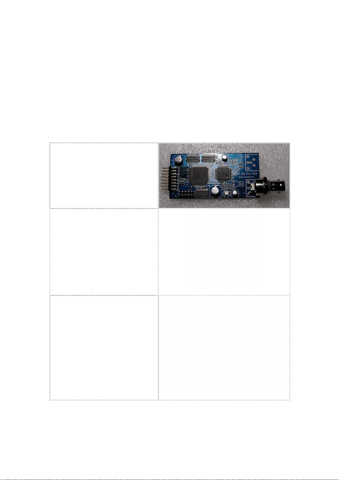
2. Introduction:
The BT601Pro SDI Mod. Kit converts the standard parallel BT601/BT656 digital video signal generated by
the MPEG decoders of DVD players or set-top boxes to SDI (Serial Digital Interface) signal for video signal
transmission in order to avoid unnecessary digital-to-analog and analog-to-digital conversions which will
cause video quality loss. SDI can keep video signal digital, from the source to the video processor / scaler
then to the digital displays, i.e. the highest video picture quality.
2. Features:
Standard compliant SDI output, compatible with major SDI capture devices
Supports major DVD players and set-top boxes with ITU BT601/BT656 video output
Provides 1 SDI output
One BNC connector is pre-installed for easy installation
Provides fully digital output directly from a MPEG decoder to SDI capture card/video processor
Status LED turns on when 27MHz clock signal is detected
Color ribbon cable are included to facilitate the installation
3. System Requirements:
-The video signal from the MPEG decoder must be ITU BT601 compliant (8-bit video data with embedded
sync + 27MHz video clock).
-DC 5V (usually provided by the DVD player or the set-top box) is required to power the kit.
Page 2
4. Specifications:
J6S3D2S2S1
-Dimensions (H x W x D): 1.5cm x 5cm x 4cm, 1.5cm x 7cm x 4cm including the BNC connectors
-Power consumption: 0.3W
-One Serial Digital Interface (SDI) Output
-One BT601/BT656 Input LED Indicator
-Table 1, PIN assignments:
- LED (D2) lights up when 27MHz
clock signal is detected.
- D0 & D1 are for 10-bits SDI
applications, they are not used for
DVD/set top box SDI modification.
- 8bits (D2-D9).
- D2 is the less significant bit.
- D9 is the most significant bit.
- Clock
- Ground
- VSYNC/Field-id
- HSYNC
- +5V
- GND
(Twisted clock and ground cable may lower the
noise of the clock signal)
Pin-color relationship
D0 – brown
D1 – red
D2 – orange
D3 – yellow
D4 – green
D5 – blue
D6 – purple
D7 – grey
D8 – white
D9 – Black
CLK – Brown
GND – Red
HSync – Orange
VSync/F – Yellow
GND – Green
+5V – Blue
Page 3

6. Installation:
1. Connect all D2-D9 pins to the appropriate MPEG decoder output pins of your DVD player or set-top
box. The D0 and D1 pins are not used because the digital video output of the MPEG decoders in
the DVD players and set-top boxes is 8-bit data only.
2. Connect the 5 volt and ground to the appropriate location on the circuit board of the DVD player or
set-top box.
7. Configuration
There are three 8-bit DIP switches to configure the BT601Pro SDI mod kit.
Table 2-1: S1 definition
1 2 3 4 5 6 7 8
HPOLARITY HOFFSET10 HOFFSET9 HOFFSET8 BT601
Mode
Table 2-2: S2 definition
1 2 3 4 5 6 7 8
VOFFSET7 VOFFSET6 VOFFSET5 VOFFSET4 VOFFSET3 VOFFSET2 VOFFSET1 VOFFSET0
Table 2-3: S3 definition
1 2 3 4 5 6 7 8
HOFFSET7 HOFFSET6 HOFFSET5 HOFFSET4 HOFFSET3 HOFFSET2 HOFFSET1 HOFFSET0
For S1/S2/S3 switches, ON=0, OFF=1
VPOLARITY HDiff1 HDiff0
HPOLARITY: H-sync polarity
0(ON): negative polarity
1(OFF): positive polarity
VPOLARITY: V-sync/F polarity
0(ON): negative polarity
1(OFF): positive polarity
BT601 MODE:
0(ON): the input signal is BT601 format; SAV/EAV will be inserted
1(OFF): pass-through mode, input signal is BT656 format (embedded sync)
HOFFSET:H-Sync offset, unit: clock cycle, total 11 bits (1 pixel=2 clock cycles)
H-sync based on ITU BT.601, the firmware of the BT601-Pro will automatically detect PAL or NTSC video
format)
If H-Sync is N cycles ahead of the standard value, please set
HOFFSET= 862 – N, where N <= 862
If H-Sync is N cycles behind of the standard value, please set
HOFFSET= 862 + N, where N<=851
If the color of the picture is wrong (swapped Cr and Cb) or pink (swapped Y and Cr/Cb), please increase or
decrease the HOFFSET value by M, where M=1, 2 or 3.
Standard value: 862 (862 is the magic number which is corresponding to the standard position of
Page 4

VOFFSET:V-sync/Field-id offset, unit: line, total: 8 bits
Standard value:128 (128 is the magic number which is corresponding to the standard position
of V-sync based on ITU BT.601, the firmware of the BT601-Pro will automatically detect PAL or NTSC video
format)
If V-sync/Field-id is N lines ahead of the standard value, please set
VOFFSET= 128 – N, where N <= 128
If V-sync/Field-id is N lines behind of the standard value, please set
VOFFSET= 128 + N, where N <= 127
For most of the MPEG2 decoders, HOFFSET for NTSC is the same as HOFFSET for PAL. Some MPEG2
decoders (e.g. the one used in Denon 3910), the HOFFSET for NTSC is different from HOFFSET for PAL so
we offer a parameter called HDiff to adjust the difference. In these cases, HOFFSET is an offset value for
NTSC mode. For PAL mode, its offset value is the sum of HOFFSET and HDiff values. HDiff refers to the
horizontal offset difference between NTSC and PAL and it is set with a value of 0 (setting 'ON' for both pin)
as default so that the system will display image correctly both in NTSC and PAL mode. These settings aim
at correcting the image color problem due to the color differences between PAL and NTSC color.
Default values:
+-**HPOLARITY: negative (ON)
VPOLARITY: negative (ON)
BT601 Mode: ON (input is BT601 signal)
HOFFSET: 862
VOFFSET: 128
HDiff: 0 (HOFFSET for NTSC = HOFFSET for PAL)
1 2 3 4 5 6 7 8
S1 ON ON OFF OFF ON ON ON ON
S2 OFF ON ON ON ON ON ON ON
S3 ON OFF ON OFF OFF OFF OFF ON
8. Finish:
1. After the modification, power up the DVD player or set-top box and the LED (D2) on the kit should
light up indicating that it is receiving a 27MHz clock signal from the MPEG decoder of the DVD player or set-top box.
2. Connect BNC cables from the SDI output of this Mod. Kit to your SDI capture device.
Example: An SDI Mod. Kit installed on a Philips 963SA DVD player is shown in the following picture.
Page 5

Example 1: the pin assignment of Philips 963SA’s MPEG2 decoder (from left to right):
24 (Gnd) 21 (Field-id) 20 (H-sync) 18 (Clk) 16 (D2) 14 (D3) 12 (D4) 10 (D5) 9 (+5V) 8 (D6) 6 (D7) 4 (D8) 2
(D9) 1 (Gnd)
Settings of BT601Pro SDI Mod. Kit for Philips 963SA DVD player
1 2 3 4 5 6 7 8
S1 ON ON OFF OFF ON ON ON ON
S2 OFF ON ON ON ON ON ON ON
S3 ON OFF ON OFF OFF OFF OFF OFF
Example 2: Settings of BT601Pro SDI Mod. Kit for Denon 3910 DVD player
1 2 3 4 5 6 7 8
S1 ON ON OFF OFF ON ON OFF OFF
Page 6

S2 OFF ON ON ON ON ON ON ON
S3 ON OFF ON OFF OFF OFF OFF ON
 Loading...