

Pixel SRDBS User Manual
Satellite Radio – DBS Multiplex Kit
Model: SRDBS
Transmit Satellite Radio Signals on
the Same Cable used for DBS TV
Satellite Radio
Antenna *
Pixel Model: PRO-500 or
Pixel Model: PRO-600
* Compatible only with Pixel antennas. Damage
may result to non-compatible antennas
DIRECTV or DISH Multi-Switch *
* Note: In some DBS systems this
switch is built into the DIRECTV
or DISH antenna
• Works with any DISH or DIRECTV System
• Compatible with XM and Sirius
• Compatible with DIRECTV SWM systems
• Compatible with Tuner Modules for any
“Sirius-Ready” or “XM-Ready” Home
Theater Receiver
• Signal splitters available for Multi-Receiver
lations (Model SR-4)
Instal
• No external power supply required
Up to 200 feet
of RG-6 cable
SRDBS-O
To IRD’s
Kit Includes Items Shown
Below. All other Items sold
separately
SRDBS-I
3 ft. F-Female to SMB-plug cable
DIRECTV or DISH Receiver
(IRD)
Phone: (303) 526 – 1965 www.PixelSatRadio.com
XM or Sirius Receiver
(or Tuner Module for any “XM-Ready” or
“Sirius-Ready” Home Theater receiver)
Model: SRDBS Satellite Radio / DBS TV Multiplex Kit Installation Instructions
Model: SRDBS Satellite Radio / DBS TV Multiplex Kit
This kit is designed to multiplex a 2.33 GHz satellite radio signal (either Sirius, XM or both) on the same wire used to send
DBS signals to DirecTV or DISH receivers. It includes the necessary components to inject the signal on the cable and to
remove it at the satellite TV receiver. It will operate with all legacy and standard DirecTV and DISH Network receivers and will
also operate with newer DirecTV Single Wire Multi-Switch (SWM) systems. It is only compatible with Pixel satellite radio
antennas Model PRO-500 or PRO-600. It is not recommended for use with other manufacturer’s satellite radio
antennas or antennas that are shipped with XM or Sirius radios, as damage may occur to these other antennas.
System Operation. with legacy and standard DirecTV and DISH Network Systems
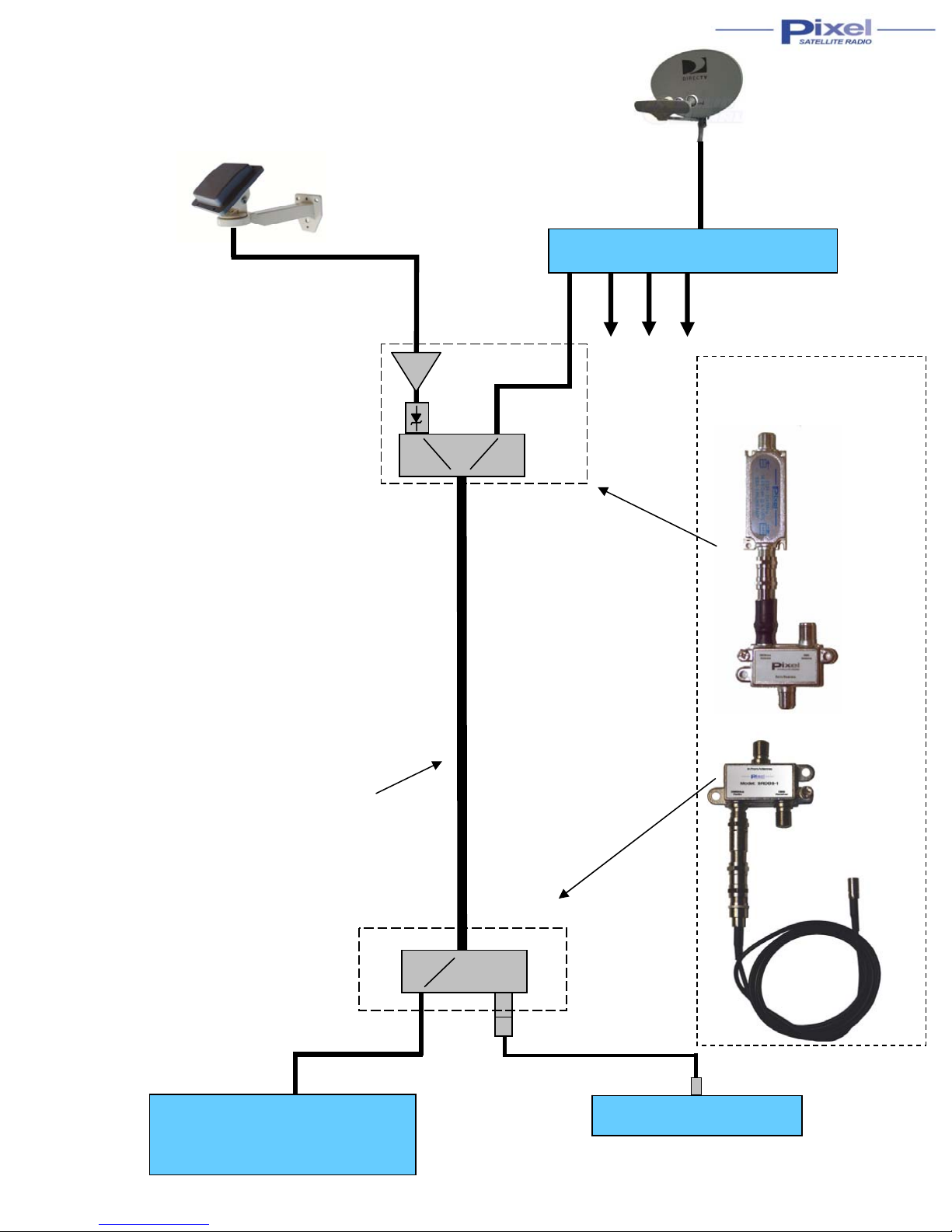
Figure 1 shows the setup for use with any DBS receiver system (except DirecTV SWM-single wire multi-switch systems
shown in Figure 2). The components provided for this include the following:
SBA -1 satellite radio line amplifier
One 7.5 VDC voltage reducer
Signal combiner (all ports power passing) Model SRDBS-O
Signal splitter (one port power passing) Model SRDBS-I
3 ft F-female to SMB-plug cable
Impedance terminator
The satellite radio antenna is connected to the line amplifier shown in Figure 1 and the signal is combined wit h the satellite TV
signal that would normally be connected directly to one of the DISH or DirecTV receivers. At the DISH or DirecTV receiver the
signals are split to the satellite radio and to the satellite TV receiver
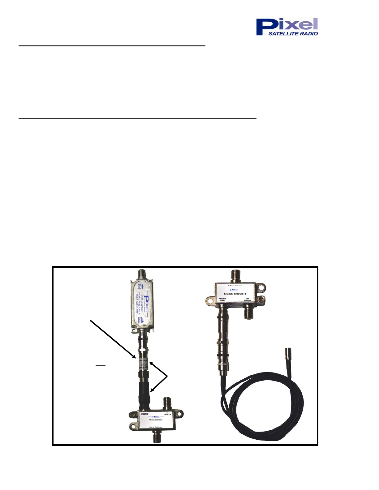
The picture below shows the signal combiner and signal splitter that are pre-assembled ready for use except that
one of the 7.5 VDC voltage reducers shown in the diagram must be removed for use with standard or legacy DBS
systems:
CAUTION: Do not plug the satellite radio antenna into any other port on the signal combiner than
that shown. The 18 V DC for the satellite TV antenna will damage the satellite radio antenna.
SRDBS-O
Remove this voltage
Remove this voltage
reducer when used
reducer when used
with DISH or Standard
with DISH or Standard
13 - 18 VDC DIRECTV
13 - 18 VDC DIRECTV
Systems.
Systems.
WARNING: Do not
WARNING: Do not
remove when u s ed with
remove when u s ed with
DIRECTV SWM systems
DIRECTV SWM systems
(which operate between
(which operate between
21-29 VDC.) Damage to
21-29 VDC.) Damage to
the satellite radio
the satellite radio
antenna will occur.
antenna will occur.
SRDBS-O
Two 7.5 VDC
voltage reducers
SRDBS-I
SRDBS-I
www.PixelSatRadio.com 1 Phone: 303-526-1965
 Loading...