

Page 1

RF PRO-1B INSTALLATION INSTRUCTIONS
This active magnetic loop antenna is designed for reception of signals over the range of 50 kHz to 30 MHz. It
includes a very high dynamic range low-noise preamplier that can be mounted to a pole or any at surface. The
preamplier is designed for minimum intermodulation distortion in the presence of very high level signals that would
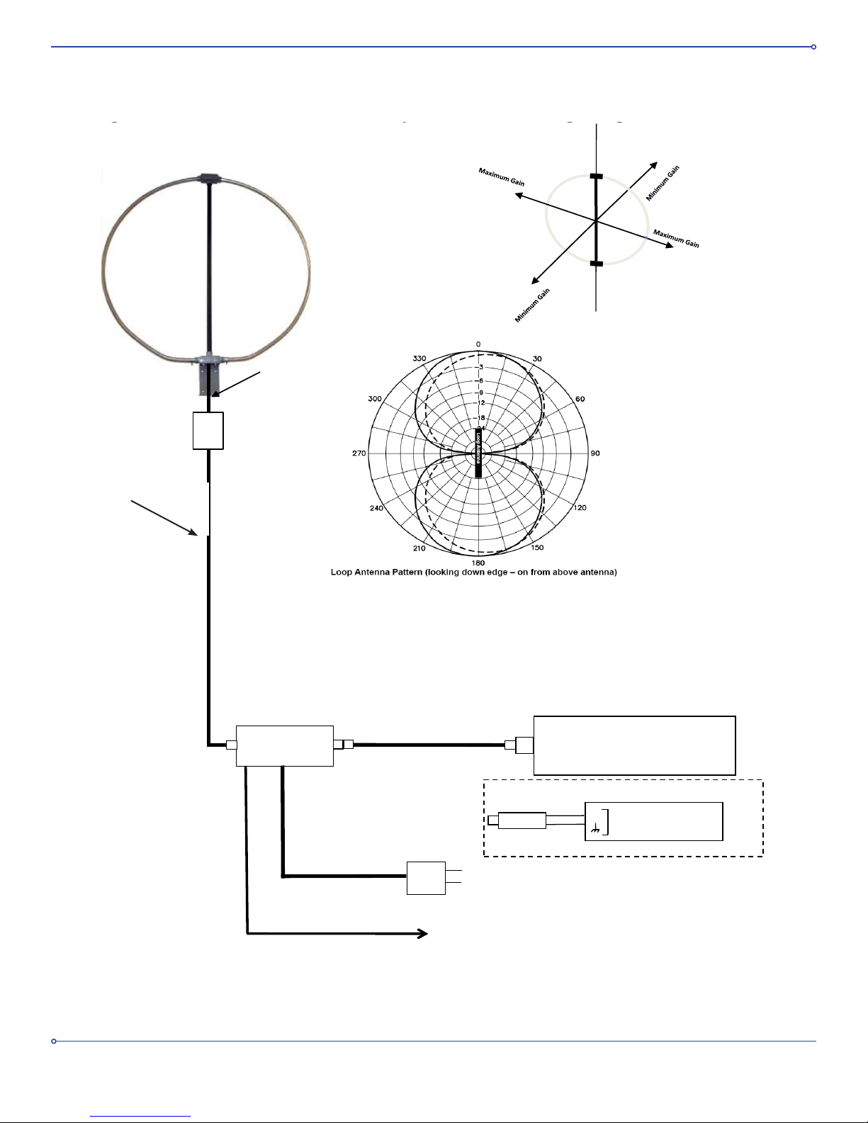
normally overload most ampliers. For proper operation the preamplier needs to be powered as shown in the
diagram shown in Figure 1 with the supplied power inserter and power supply that duplexes DC power on the same
cable carrying the preamplier’s output. The antenna should be oriented in the proper direction to maximize reception
of the desired signals (see details below). For best performance, the amplier should be installed near the antenna to
avoid amplifying low level local interference that may enter the coaxial cable leading from the loop antenna to the
preamplier’s input.
Cautions:
• This is a receive-only antenna. Do not connect it to a transmitter as it will be damaged and void your
warranty
• Do not inadvertently connect the 20 VDC output of the power inserter to your receiver’s antenna input as
your receiver may be damaged.
• See attached cautions and warnings relative to lightning protection and antenna installation near high
voltage power lines.
• When operating with nearby transmitting antennas, follow the instructions below to avoid over-driving (or
damaging)yourreceiver’sinputordamagingtheloop’slow-noiseamplier.
Supplied Components (see Figure 16)
QTY Description
1 Loop antenna
1 30 dB preamplier
1 L-bracket
2 Saddle clamps
2 U-bolts
1 lot Mounting Screws and washers
1 Coaxial- Seal package
1 24 VAC wall mount transformer
1 3 ft F-male to F-male jumper cable
1 1 ft F-male to F-male water-proof jumper cable
1 PL-259 Adapter
1 20 VDC power inserter
1 Twin lead to F-female adapter
1 RCA- plug to RCA- plug cable and Y adapter
1 Grounding Lug
2 Nylon shoulder washers (.375 inch)
2 Nylon at washers (.25 inch)
1 Instruction Manual
1
Page 2
TO
RADIO
TO AMP
OUTPUT (20
VDC)
MODEL P-92A
POWER
INSERTER
PL-259
ADAPTER
RADIO
RECEIVER
24 VAC Wall Mount
Transformer
CAUTION: Do not inadvertently connect 20 VDC
output of Power Inserter to Radio’s antenna input.
The 20 VDC may damage the radio
Figure 1. RF PRO-1B Active Loop Antenna Wiring Diagram
RG-6 Cable
(Not Supplied
)
Input
Output
27 dB
Preamplifier
Model RF30A
Vertical Axis
1 Ft Jumper Cable
115 VAC
Ant
Red
Black
RADIO
RECEIVER
Supplied Twin
Lead Adapter
Alternate Interface for Radios with Twin
Lead Antenna Input
KEY
To KEY output of transceiver (optional)
Power Inserter
(see Figures 4 & 15)
Figure 1. RF PRO-1B Active Loop Antenna Wiring Diagram
(sold separately)
CAUTION: Do not inadvertently connect 20 VDC
output of Power Inserter to Radio’s antenna input.
The 20 VDC may damage the radio.
2
Page 3

Positioning the Antenna
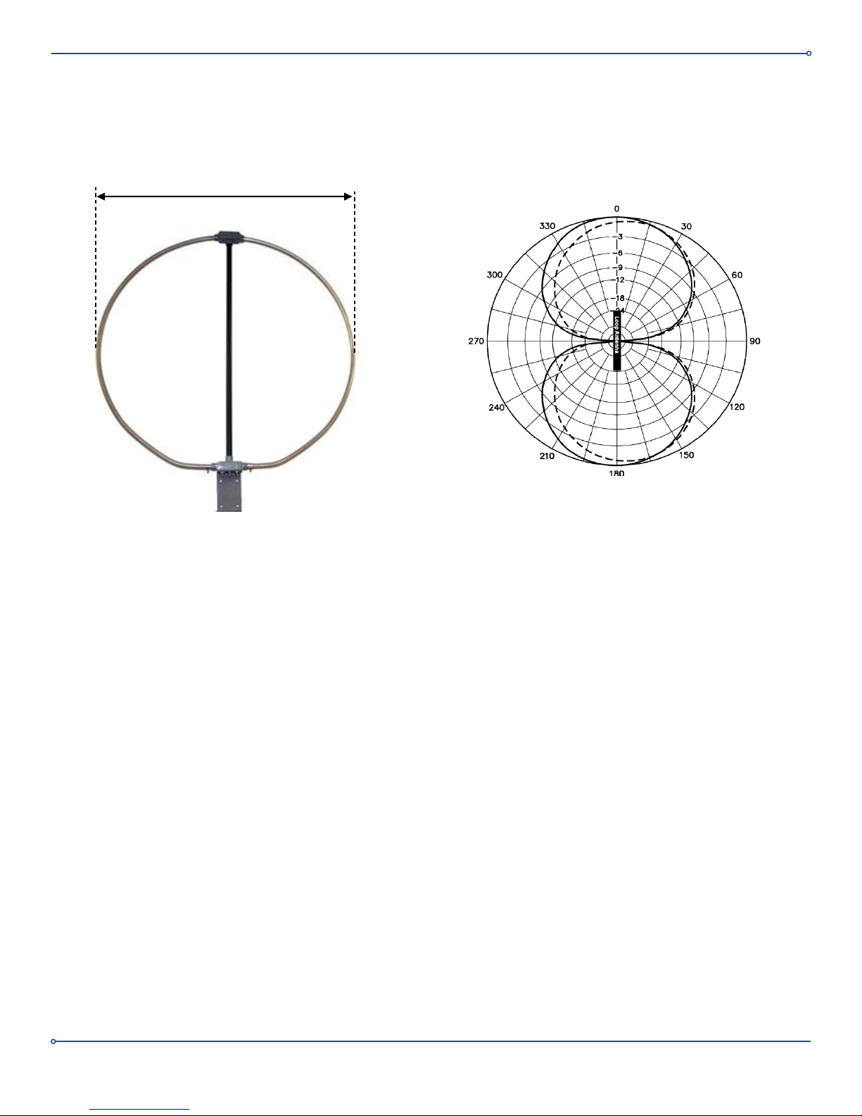
This antenna has a directional ‘Figure Eight’ pattern with two deep 25- 30 dB nulls as shown in the diagram in Figure 1,
so for maximum daytime low-angle ground wave reception of a desired signal it should be oriented so that the
imaginary plane in which the loop rests should be vertical to the ground and should, if extended, pass through the
general location of the signal’s transmitter. There is a label on the antenna’s upper junction box that shows the
proper pointing directions for maximum signals and the nulls. At night, for reception of high- angle sky waves
this antenna is less directional and the nulls are far less prominent.
For best results it should be located as far away as possible from any metal objects that could distort or shield the
antenna’s reception like gutters, downpipes, metal plumbing and aluminum foil backed thermal insulation. It can be
positioned indoors or outdoors at least 5 feet above ground level, but for best results it should be as far as possible
from sources of interference such as AC power cables, cat 5 network cables, uorescent lights, light dimmers,
computers and at panel TV’s. If located outdoors it can be camouaged with shrubbery. Ideally a location outdoors
at least 20 feet away from any buildings will yield superior results. It can be mounted to any pole up to 2 inches in
diameter or attached to a at surface or wall via the included L-bracket.
Use with Near-By Transmitting Antennas
The antenna’s low-noise preamplier will withstand RF input levels of at least 30 dBm without failure. In tests with a
1,500 Watt transmit amplier and a ¼ wave vertical transmitting antenna we found that the worst- case loop output
power into the preamp was 10 dBm when the antenna was located 25 ft from a vertical radiator and adjusted for
maximum coupling. This would indicate that at 25 ft separation there is a 20 dB safety margin. The other factor to
consider however is that with this kind of input signal (+10 dBm) the preamplier’s 27 dB gain will cause it to saturate
and output 1.3 watts into the connected receiver. This high saturated output level is a byproduct of the excellent
intermodulation distortion performance of this preamplier, but while most receivers have some sort of input protection
and possibly an internal transmit / receive switch that disconnects or shorts the input when transmitting, we cannot be
sure of what the radio’s protection limits are and we don’t want to be responsible for any damage that may result.
Hence included in the loop’s power inserter is a relay that can be actuated by the “KEY” output of a typical
transceiver. When actuated, the relay disconnects power from the antenna’s preamp. A green LED on the power
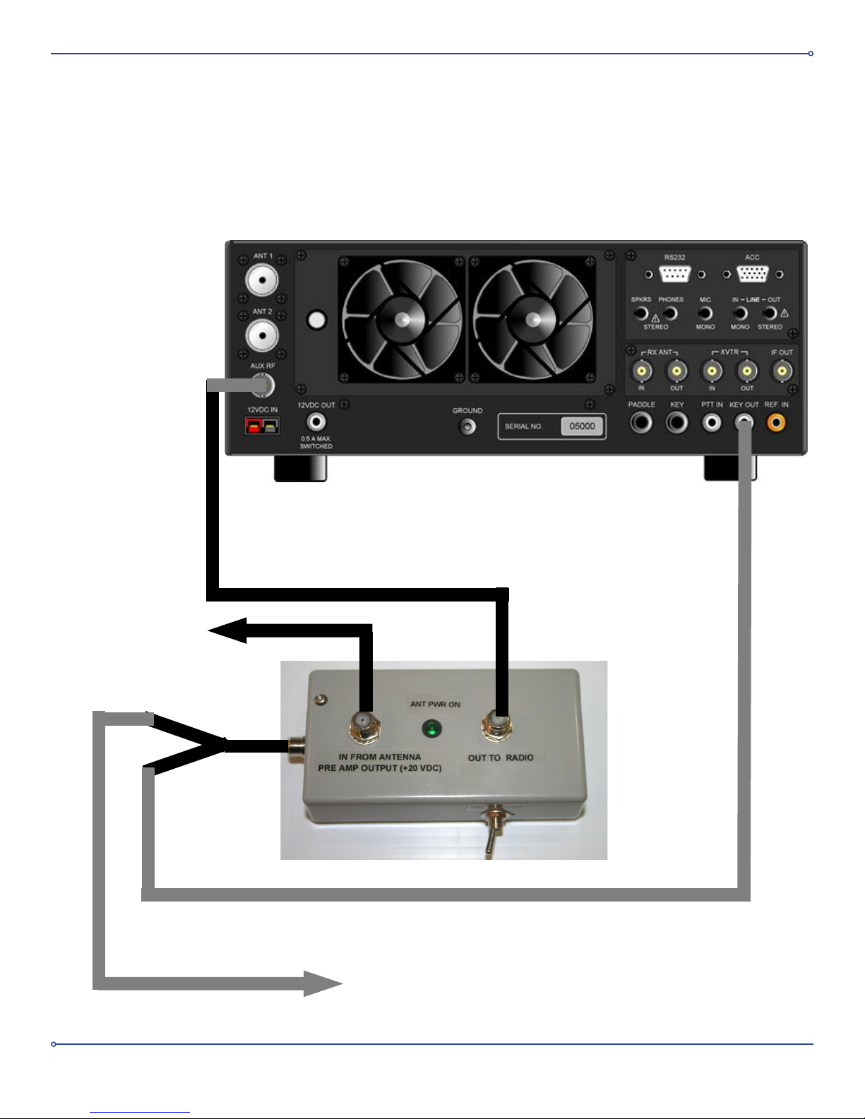
inserter is illuminated when power is applied to the preamp. An RCA-plug to RCA-plug cable is included with the
accessories to connect the KEY output of your transceiver to the RCA jack on the side of the power inserter. An RCA
Y-adapter is also included to enable connecting the KEY signal from your transceiver to other equipment. (See
Figures 2 and 3).
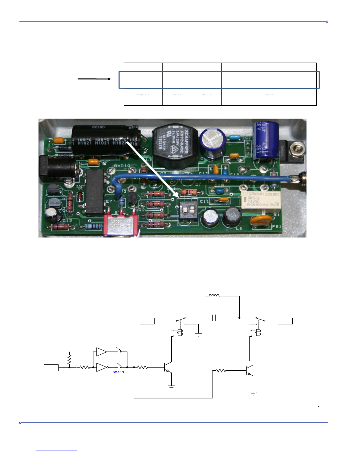
The relay’s actuation circuit is designed to operate with a typical transceiver’s 12 VDC “KEY” signal. The power
inserter has internal DIP switches that can be programmed to harmonize relay actuation with the proper state of the
transceiver’s KEY signal. The default setting is such that when the KEY output is “low” (less than 0.7 VDC) the relay
turns on and disconnects the preamp’s power and the connection to your receiver is grounded through a resistor. If
the KEY signal is “high” or greater than 1.2 VDC the relay is not actuated and power is applied to the amplier and
connection is made to your receiver. If the KEY input to the power inserter is left open or disconnected, then power is
always applied to the preamp. If your transceiver has a “KEY” output that goes high on transmit, then you can reverse
the polarity of the power inserter relay actuation by removing the power inserter’s base plate and programming the
DIP switches on the PC board in accordance with the table shown in Figure 4.
A simplied schematic of the relay interface circuit is shown in Figure 5. Note that the KEY input is pulled up internally
via a 10K ohm resistor to the “high” state. If your transceiver’s KEY output is not compatible with this interface circuit
and does not operate the power inserter relay, please contact our customer service (303 526 1965,
[email protected]) for assistance.
3
Page 4
To Key Input on Transmitter Amplifier
( if you have one)
To Loop Preamp
Back of Elecraft K3
RF PRO-1B Power Inserter
Figure 2. KEY Wiring For RF PRO-1B Loop Antenna
Typical Transceiver
Figure 2. KEY Wiring for RF PRO-1B Loop Antenna
Typical Receiver
Back of Elecraft K3
To Loop Preamp
RF PRO-1B Power Inserter
ToKeyInputonTransmitterAmplier
(if you have one)
4
Page 5
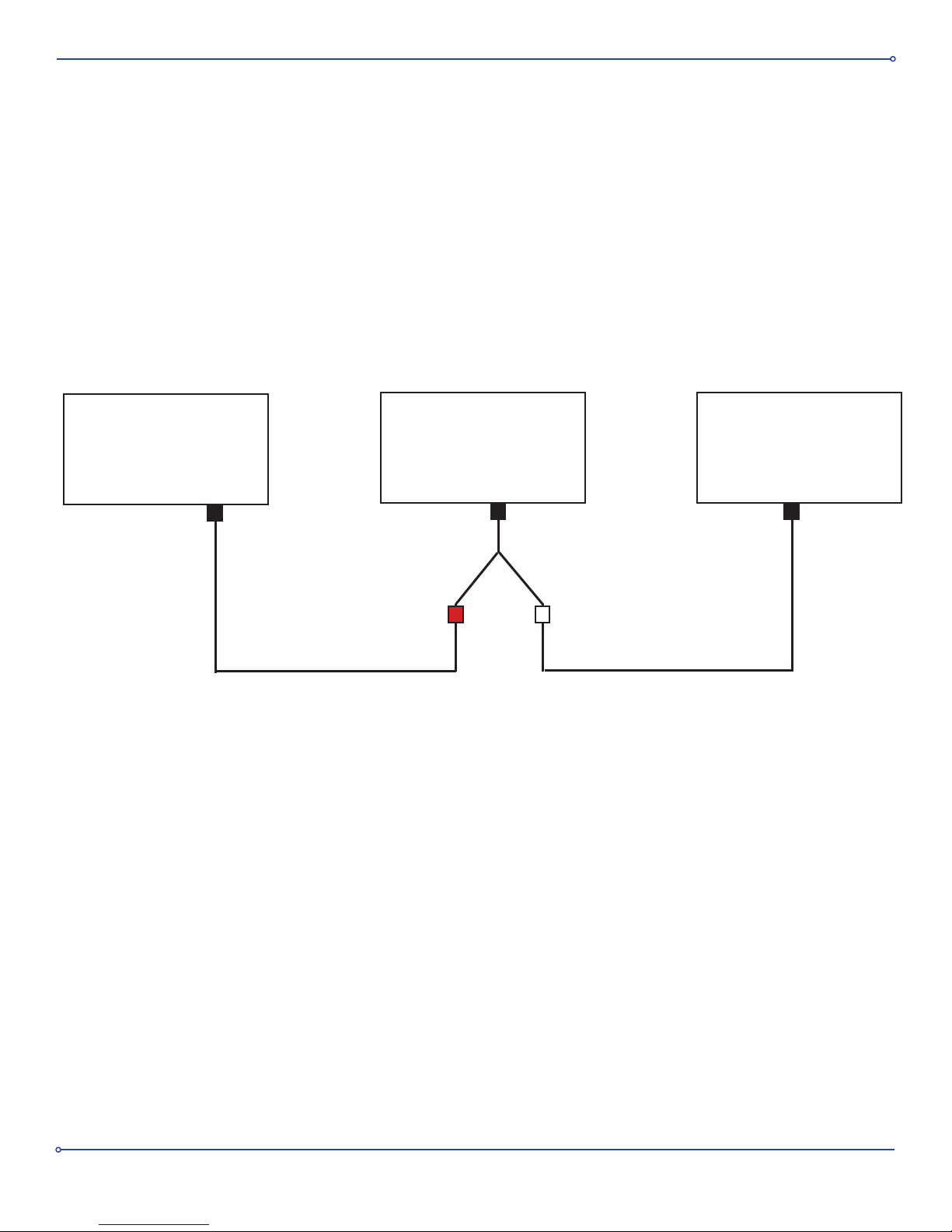
Figure 3. KEY Wiring for RF PRO-1B Loop Antenna
Transceiver
KEY
Out
RF PRO-1B
POWER INSERTER
KEY
Y Adapter
Amplier
KEY
In
5
Page 6
KEYINPUT Switch1 Switch2 20VDCANTENNAPOWER
LOW OFF ON OFF
HIGH OFF ON ON
Default
Settings
LOW
ON
OFF
ON
HIGH ON OFF OFF
LOW≤0.7VDC
HIGH≥1.2VDC
DIPSwitch
ON
1
2
Figure4.PowerInserterDIPSwitchSettings
Figure5.SimplifiedRelayInterfaceSchematic
To Loop Preamp
(+20 VDC)
Output to Receiver
+20 VDC
10k
10k
+20 VDC+20 VDC
+20
SW 1
Key f rom Transciever
SW 2
Figure 4. Power Inserter DIP Switch Settings
Figure 5.SimpliedRelayInterfaceSchematic
6
Page 7

Cable
For best results the cable run from the indoor power inserter to the external amplier should be quad shielded RG-6 cable
with male F connectors on each end.
This cable is available with high-quality compression t water-proof F-connectors pre-attached that have internal O-rings
to keep moisture out.
Pixel part numbers:
C-50 50 feet
C-100 100 feet
C-150 150 feet
C-200 200 feet
Standard shield, high quality RG-6 cable can also be used; however the cable’s ability to reject external interference is
reduced by typically 10 dB.
If the cable run from the power inserter to the antenna’s preamplier is longer than 200 feet, then RG-6 cable that has
a solid-core copper center conductor should be used such as Belden 1829AC to minimize DC loss.
WaterproofF–Connectors&WeatherProong
The one foot long RG-6 jumper cable included with the accessories (see Figure 6) is used to connect the output of the
loop to its preamp. This cable uses specially designed F-connectors to eliminate moisture ingress. A package of COAX
seal is supplied for additional weatherproong. Follow the instructions on the side of the package.
Mounting to a Rotator
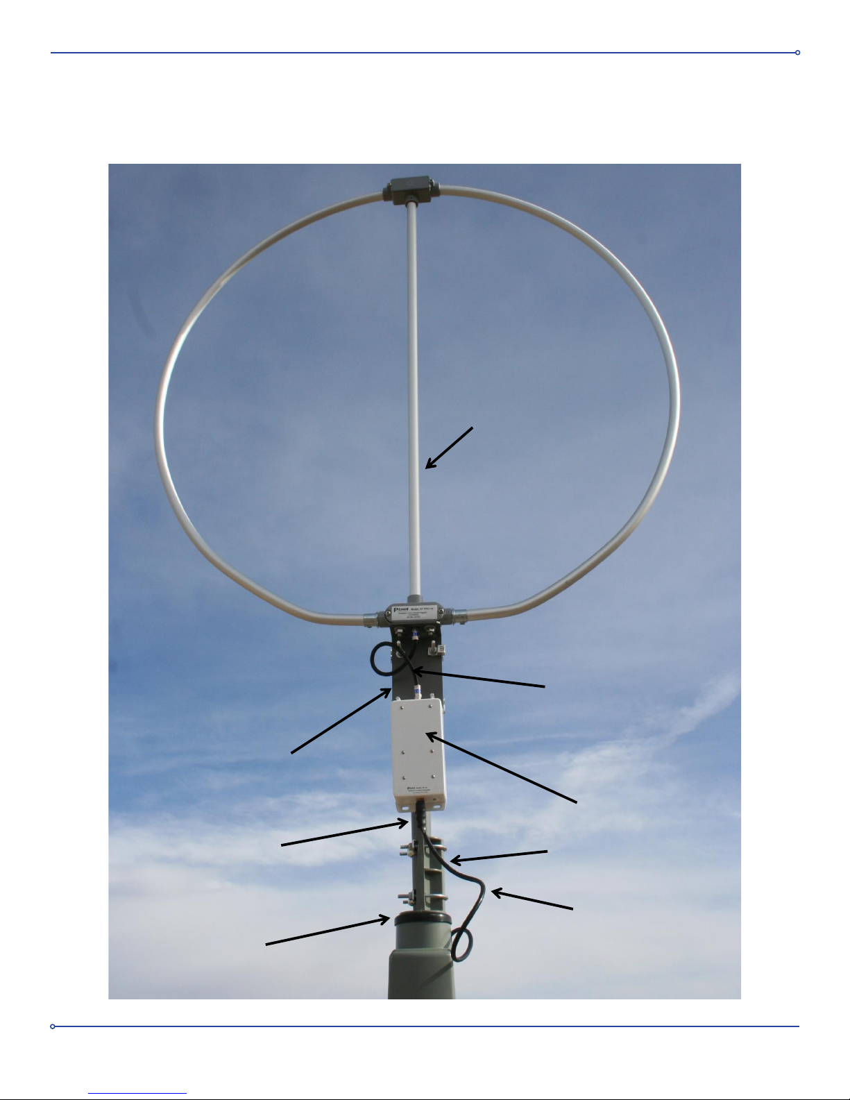
Figure 7 shows the antenna mounted to a rotator. Many users utilize this conguration to take full advantage of the
antenna’s directional characteristics. Because of the antenna’s low weight and wind loading a very low power rotator
can be used typical of the type used with TV antennas.
MountingtheAmplier
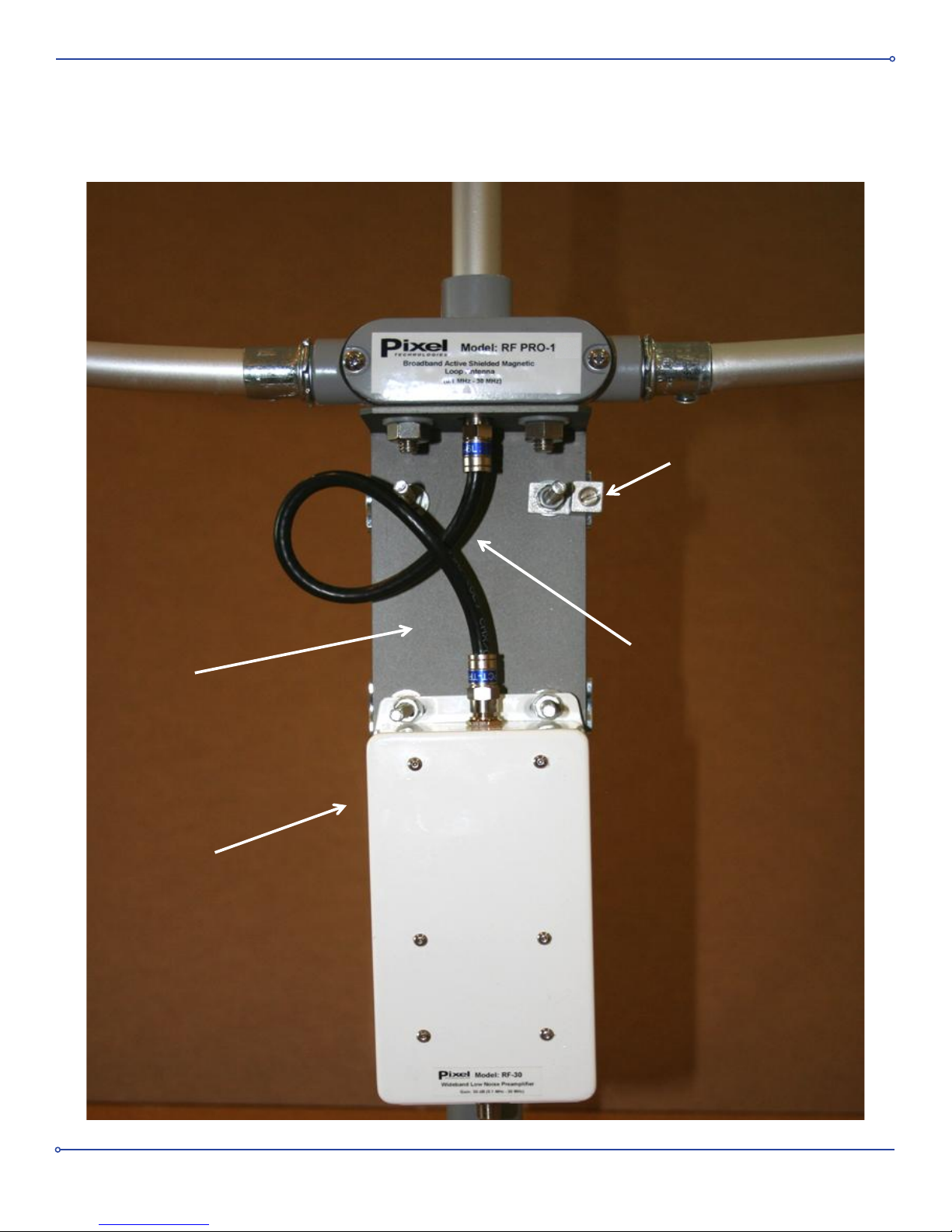
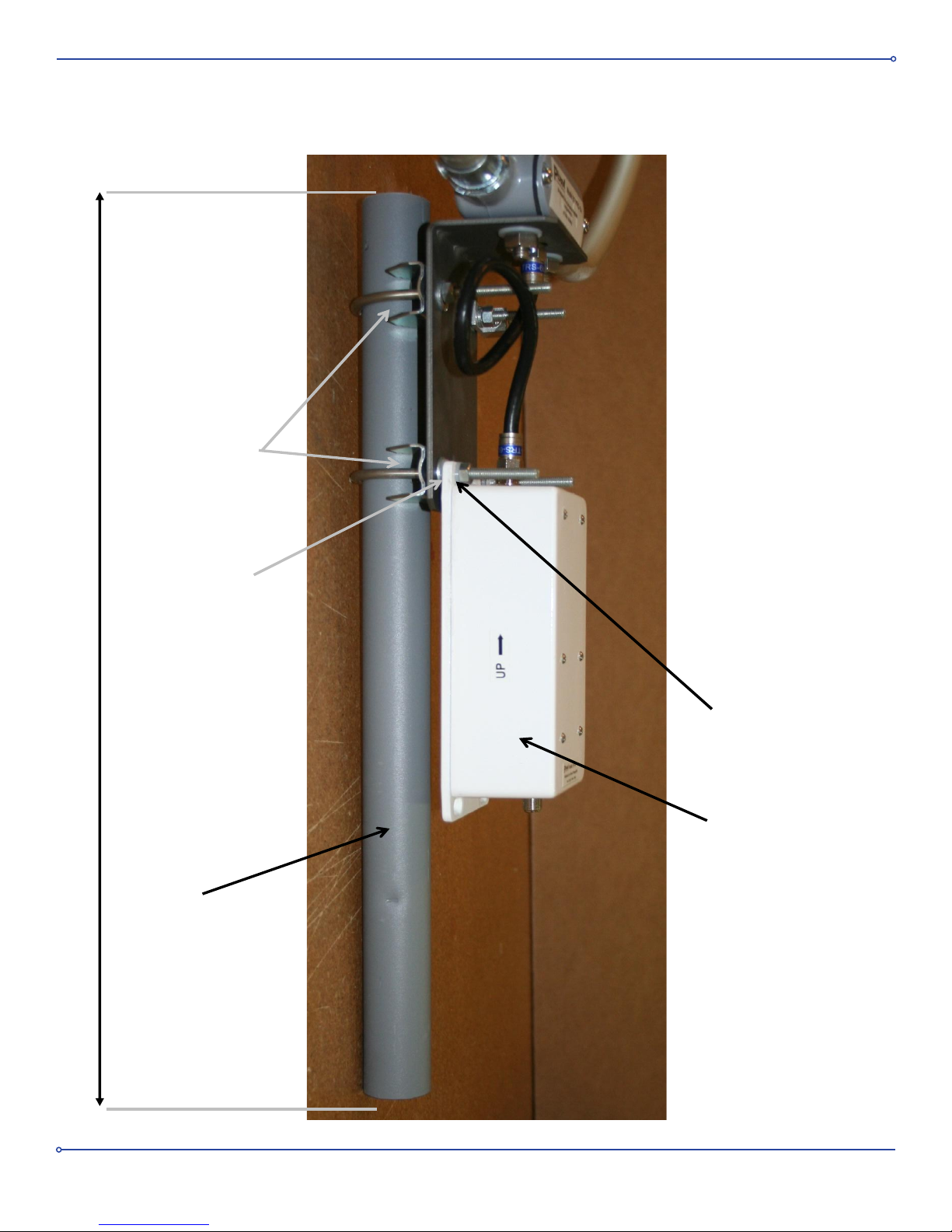
Figures 8 thru 13 show the details for pole mounting the preamplier. Nylon shoulder-washers and nylon at washers are
used to electrically isolate the metal case of the preamplier from the mounting pole. This is required to avoid ground
loops. The preamplier has two small weep holes in its base to drain any condensation that may accumulate internally
and should be orientated in the proper vertical direction as indicated by an arrow on its case. (The preamplier circuit
board is conformal coated to protect it from moisture and corrosion). A 1 foot jumper cable is supplied to connect the
output of the loop antenna to the input of the preamplier. The preamplier’s output should be connected to the 20
VDC output of the power inserter via the lead-in RG-6 cable.
7
Page 8
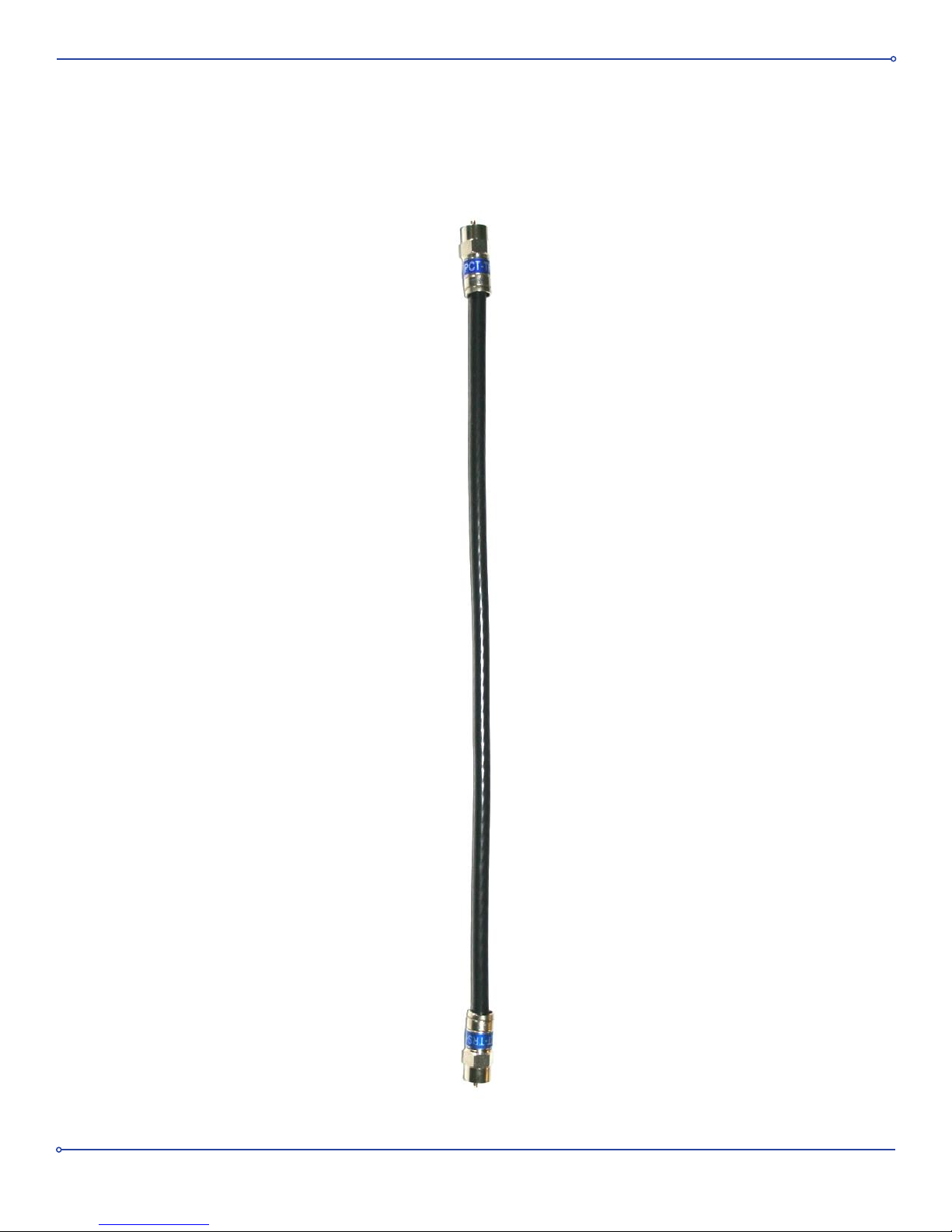
Figure 6. One foot RG-6 Jumper Cable with water-proof F-connectors.
ConnectsLoopAntennaOutputtoAmplierInput.
8
Page 9
Loop
Antenna
1 foot Jumper
L-Bracket
Preamplifier
Rotor
(Not Supplied)
Service Loop
RG-6 Cable to
Power Inserter
(Not Supplied)
Figure 7. Loop Antenna Mounted on Rotator
Coax-Seal
Figure 7. Loop Antenna Mounted on Rotor
9
Page 10
L-Bracket
1 Foot F-male
to F-male
jumper
27 dB Low Noise
preamplifier
mounted to L -
Bracket
Lightning
Grounding
Lug
B
Figure 8. Pole Mounting Details
10
Page 11
U-Bolts and
Saddle Clamps
Nylon Shoulder
Washer
Nylon Washer
Preamplifier
Figure 9. Pole
Mounting Details
(side view)
18 inches
Mast for rotor
mounting
Page 11
Figure 9. Pole Mounting Details (side view)
11
Page 12
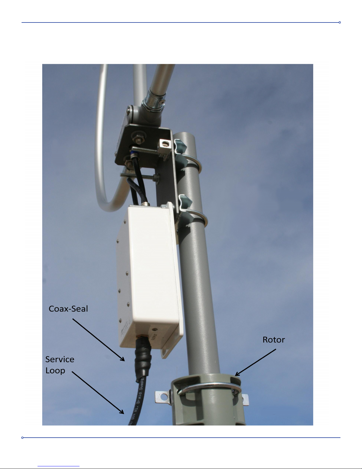
Figure 10. Antenna & Rotor Pole Mounting Details (side view)
12
Page 13
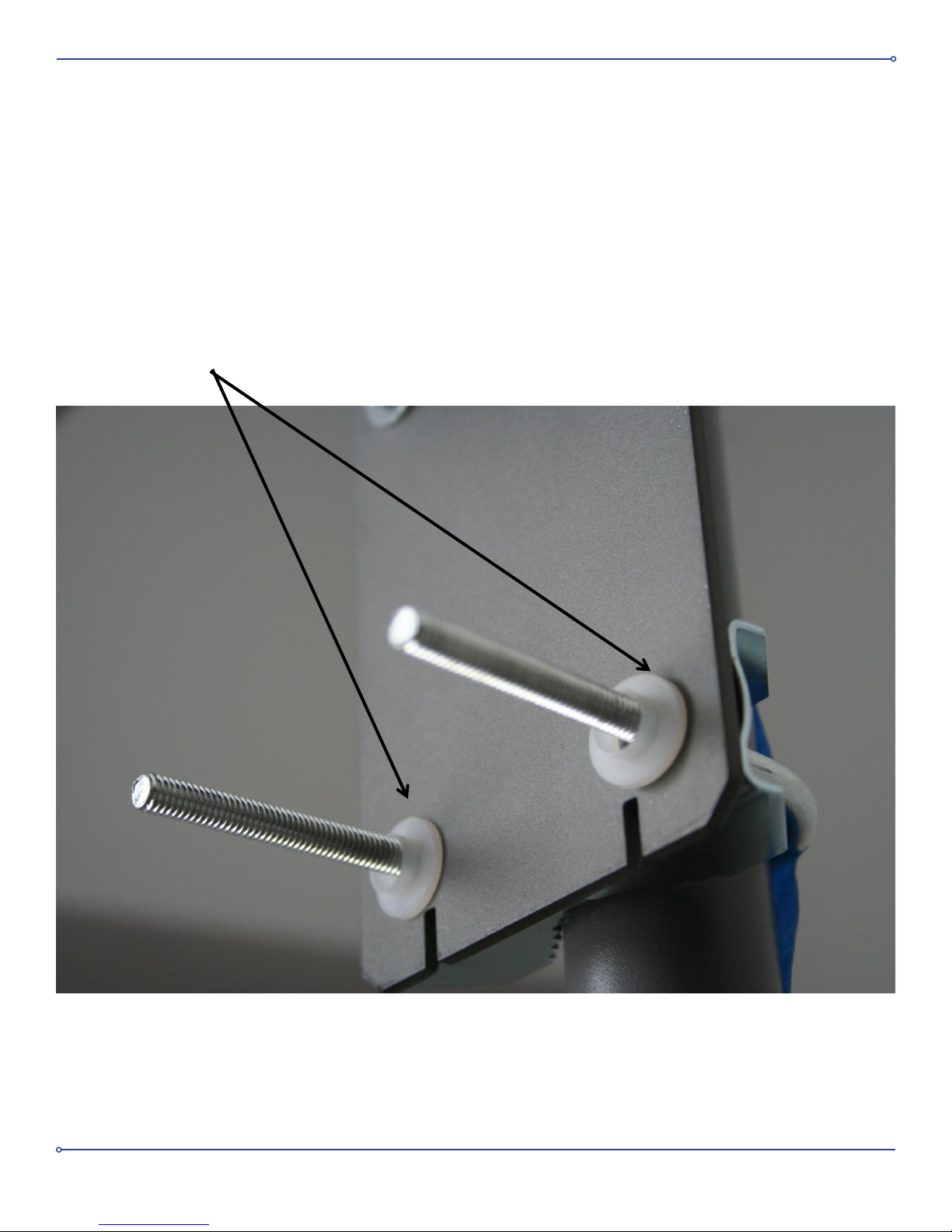
Figure 11. AmplierMountingDetails
Figure 11. Amplifier Mounting Details
Nylon shoulder washers used to electrically isolate
preamplifer from mounting pole
Nylon shoulder washers used to electrically
isolate preamplifier case from mounting pole
13
Page 14
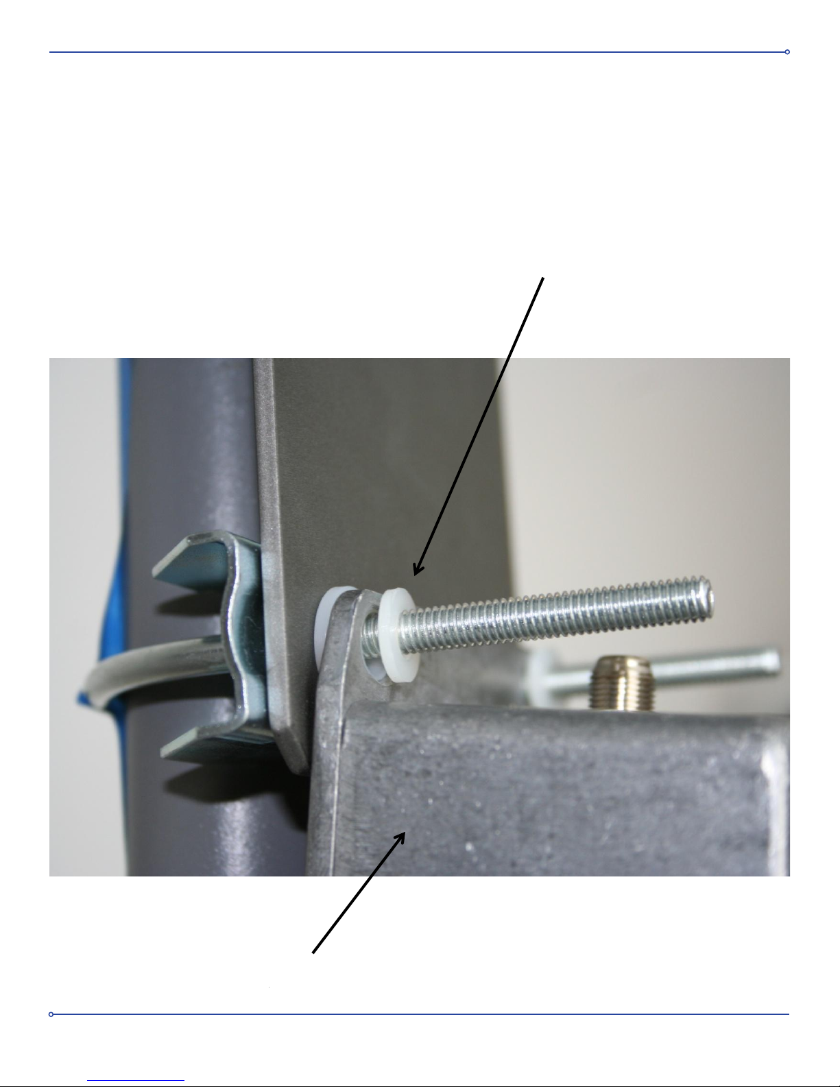
Figure 12. PreamplierMountingDetails
Figure 12. Preamplifier Mounting Details
Nylon Washer
Nylon Washer
Amplier
14
Page 15
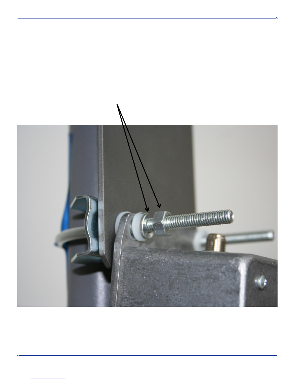
Figure 13. PreamplierMountingDetails
Figure 13. Preamplifier Mounting Details
Lock washer and Nut
Lock washer and nut
15
Page 16

Power Inserter
The power inserter contains a highly ltered linear DC regulator with an internal self resetting fuse that provides
protection from short circuits. It is designed for indoor use only. The wall mount transformer provides 24 VAC for the
power supply.
Connection Diagram
Before applying any AC power, connect the antenna to the receiver as shown in Figure 1.
Be extremely careful to avoid inadvertently connecting the 20 VDC antenna output of the power inserter to
the antenna input on your receiver. Although the power inserter has a self-resetting internal fuse that will trip
at a current draw above 400 milliamps, this will put 20 VDC on the input of your receiver momentarily that
could damage some receivers.
Grounding
The loop antenna aluminum tubing should not be grounded. It is electrically isolated from its metal L-bracket mount via
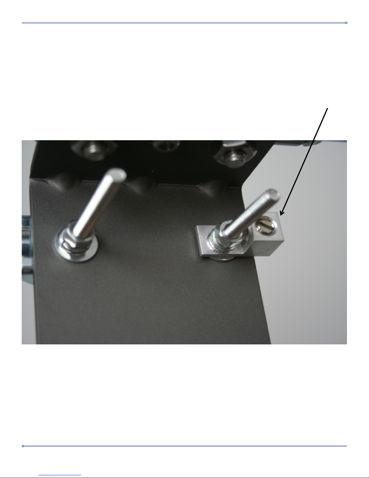
nylon shoulder washers. Do not remove these. A grounding lug is provided (See Figure 14) that can be used to ground
the mounting pole and L-bracket for lightning protection.
Warranty and Customer Service
This product is warranted for defects in materials and labor for a period of 1 year from the date of shipping. If you
require customer service, you can contact us Monday through Friday from 8:00 AM to 4:00 PM (Mountain Time at
(303) 526 1965 or e-mail us at [email protected]
16
Page 17
Grounding Lug for Lightning
Protection
Figure 14. Grounding Lug Mounting Details
Figure 11. Grounding Lug Mounting Details
Grounding Lug for
Lightning Protection
17
Page 18
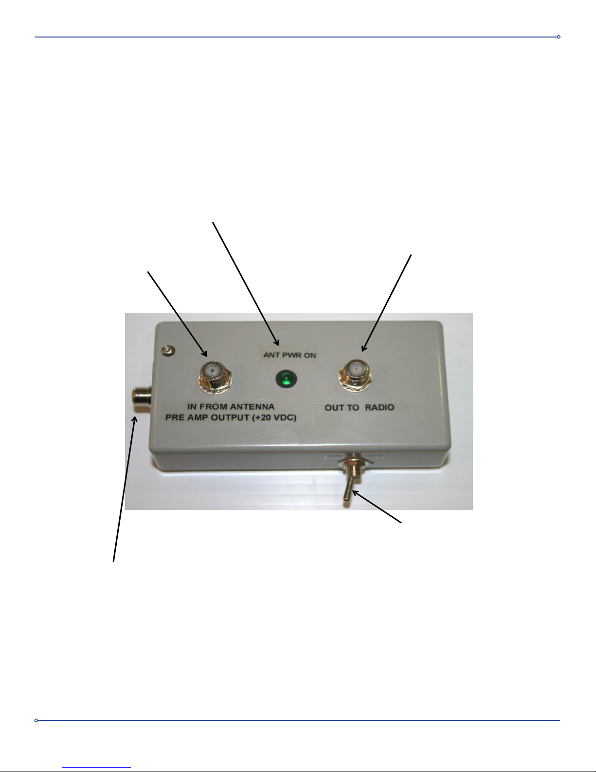
Connect to
preamp output
Connect to Receiver
Antenna Input
Connect to KEY output of
Transceiver (Optional)
Master Power on/off
ANT Power Indicator
(illuminates when the preamp is
powered)
Figure 15. Power Inserter
18
Page 19
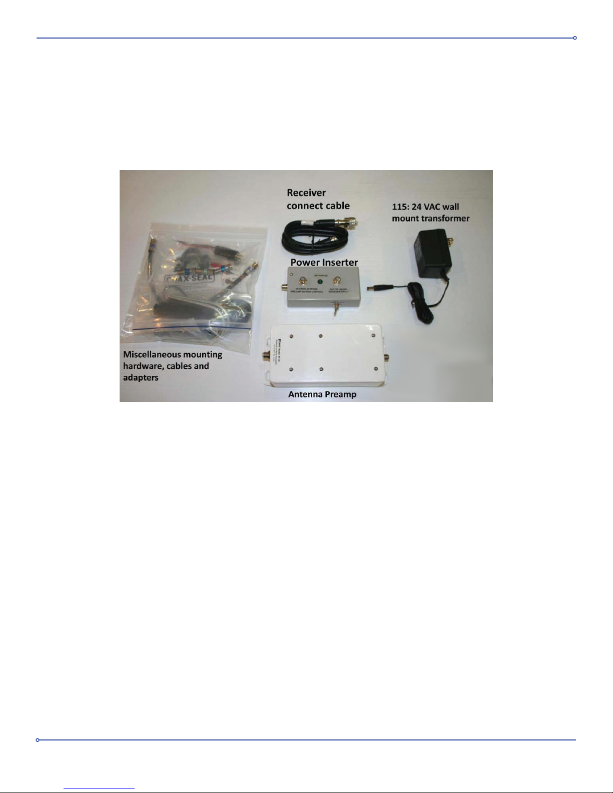
Figure 16. Supplied Accessories
19
Page 20
Magnetic Loop for Improved Reception and Noise Rejection
Model: RF PRO-1B (Receive-Only Antenna)
Shielded Active Broadband Magnetic Loop Antenna
38 inches
• Unique Loop architecture provides enhanced performance
• Very low IMD, 27 dB Low-Noise Clifton Laboratories Norton Preamp insures good performance in both strong
and weak signal environments
• Up to 30 dB rejection of locally radiated noise compared to whip antennas
• Figure eight directivity and deep nulls to further reduce interference.
• Useable coverage range: 50 kHz to 30 MHz
• Rejects power line noise
• Rugged construction, easily mounts to a pole or flat vertical surface, 38 inch dia. aluminum loop, supplied
with LNA, power inserter and DC power supply
• No manual tuning necessary
• No Home Owners Association problems; low profile, easy to camouflage and works at ground level
• Modular design for easy installation and maintenance
• Internal Transmit / Receive Switch disconnects Antenna / Preamp from receiver when transmitting
• Available preamp with internal remote controlled AM Broadcast band elimination filter (High Pass Filter)
Figure 1. Loop Antenna Pattern (looking down)
edge – on from above antenna
•MadeintheUSA
NOT YOUR FATHER’S LOOP ANTENNA
Based on the work of Dr Carl Baum for the US Air Force his “Moebius Strip Shielded Magnetic Loop Antenna”
architecture outperforms much larger antennas.
Dr Baum was a Senior Scientist at the US Air Force Research Laboratory and is the recipient of several awards from
the IEEE (Institute of Electrical and Electronic Engineers) for his work. Originally developed for a classied US Air
Force project involving the measurement of EMP (Electro Magnetic Pulse) from nuclear weapons, this design has
wide application to antennas for low- noise, interference-free radio reception over a wide frequency range. Pixel has
coupled this antenna with a custom made low-noise amplier developed for Pixel by Clifton Laboratories with very
high intermodulation distortion (IMD) specications (OIP3 = +48 dBm, OIP2 > +100 dBm) that can operate without
saturating in high AM and FM broadcast band signal environments.
20
Page 21

MAGNETIC LOOP ANTENNA ADVANTAGE
Most active antennas are the whip type and respond mainly to the electrostatic-field portion of an electro-magnetic radio
wave. The Magnetic Loop responds primarily to the magnetic-field and this ensures high rejection of nearby electric-fields. The
intensity of the electric field is usually higher than the magnetic-field when an antenna is close to interference sources such as
TVs, florescent lamps, power line wiring etc. By rejecting the electric-field there is a reduction in local interference compared to
other types of active and passive antennas. Interference reduction is further enhanced by the deep nulls of the antenna’s
'Figure-Eight' directivity pattern (see Figure 1) that can be used to null out or reduce interference coming from a specific
localized direction.
INTERMODULATION
Some active antennas generate intermodulation products which can appear as spurious signals interfering with reception. This
interference or second and third order intermodulation is caused by non linearity in the amplifier producing signals which are
usually the sum and difference of strong AM or FM Broadcast stations and their harmonics. The RF PRO-1B Loop has been
specifically designed to reduce intermodulation products to a minimum. The third order intercept point is typically +48 dBm
(OIP3) and the second order intercept point is greater than +100 dBm (OIP2 typically 110 dBm). The 1 dB compression point of
this amplifier is + 27 dBm making the levels of the intermodulation products generally far below the atmospheric and manmade noise.
ANTENNA DESIGN
The RF PRO-1B Loop Antenna consists of a rigid light-weight ¾” diameter anodized aluminum 38 inch diameter loop and a
balanced broadband amplifier that is housed in a separate enclosure that can be mounted close to the antenna on its mast or
to any nearby flat surface. This configuration permits the insertion of an optional AM broadcast band elimination high pass filter
in the amplifier that can be remotely controlled on or bypassed. This is not normally required for good performance, but is
available to provide the ultimate performance in extremely high RF signal environments. A 20 volt DC regulated power supply
and power inserter unit are provided. The antenna and amplifier
have been designed to permit the use of low-cost 75 ohm
cable (RG-6 quad-shield recommended). The maximum length is 1000 feet, but the frequency response will be a function of the
cable loss vs. length specifications. For best results the antenna should be positioned approximately 15 feet away from any
buildings or other sources of interference.
TECHNICAL INFORMATION
Frequency response: 50 kHz – 30 MHz (Nominal Gain: 27 dB ±3 dB)
DC power: 20 volts at 240 mA
OIP3: typically +48 dBm
OIP2: > 100 dBm ( typically 110 dBm)
1dB compression point: +27 dBm
NF: typically 2 dB (at 10 MHz)
Antenna Diameter: 38 inches
Antenna Weight: 3 lbs
Available RG-6 Quad-Shield Lead-In Cable
with attached waterproof connectors:
Supplied Components
QTY
Description
1
Loop antenna
1
27 dB preamplifier
1
L-bracket
2
Saddle clamps
2
U-bolts
1 lot
Mounting Screws and washers
1
CoAx Seal package
1
24 VAC wall mount transformer
1
3 ft F-male to F-male jumper cable
1
1 ft F-male to F-male water-proof jumper cable
1
PL-259 Adapter
1
20 VDC power inserter
1
Twin lead to F-female adapter
1
RCA- plug to RCA- plug cable
1
Grounding Lug
2
Nylon shoulder washers (.375 inch)
2
Nylon washers (.25 inch)
1
RCA Y adapter
Part #
Length
Price
C-50
50 feet
$ 19.99
C-100
100 feet
$ 39.99
C-150
150 feet
$ 54.99
C-200
200 feet
$ 74.99
Remote Controlled AM Broadcast Band High Pass Preamp Filter:
Model RF-30 FLT (High pass 7
th
order Butterworth) $99.99
ANTENNA DESIGN
The RF PRO-1B Loop Antenna consists of a rigid light-weight ¾” diameter anodized aluminum 38 inch diameter loop and
a balanced broadband amplier that is housed in a separate enclosure that can be mounted close to the antenna on its
mast or to any nearby at surface. A 20 volt DC regulated power supply and power inserter unit are provided. The antenna
and amplier have been designed to permit the use of low-cost 75 ohm cable (RG-6 quad-shield recommended, and
available separately). For best results the antenna should be positioned approximately 15 feet away from any buildings or
other sources of interference.
SUPPLIED COMPONENTS:
TECHNICAL INFORMATION
QTY Description
1 Loop antenna
1 27 dB preamplier
1 L-bracket
2 Saddle clamps
2 U-bolts
1 lot Mounting Screws and washers
1 CoaxSeal package
1 24 VAC wall mount transformer
1 3 ft F-male to F-male jumper cable
1 1ft F-male to F-male water-proof jumper cable
1 PL-259 Adapter120 VDC power inserter
1 Twin lead to F-female adapter
1 RCA-plug to RCA-plug cable
1 Grounding Lug
2 Nylon shoulder washers (.375 inch)
2 Nylon washers (.25 inch)
1 RCA Y adapter
1 Instruction Manual
Frequency response: 50 kHz –30 MHz (Nominal Gain: 27 dB ±3 dB)
DC power: 20 volts at 240 mA
OIP3: typically +48 dBm
OIP2: > 100 dBm (typically 110 dBm)
1dB compression point: +27 dBm
NF: typically 2 dB (at 10 MHz)
Antenna Diameter: 38 inches
Antenna Weight: 3 lbs
www.PixelSatRadio.com
[email protected]
303-526-1965
21
 Loading...