

Page 1

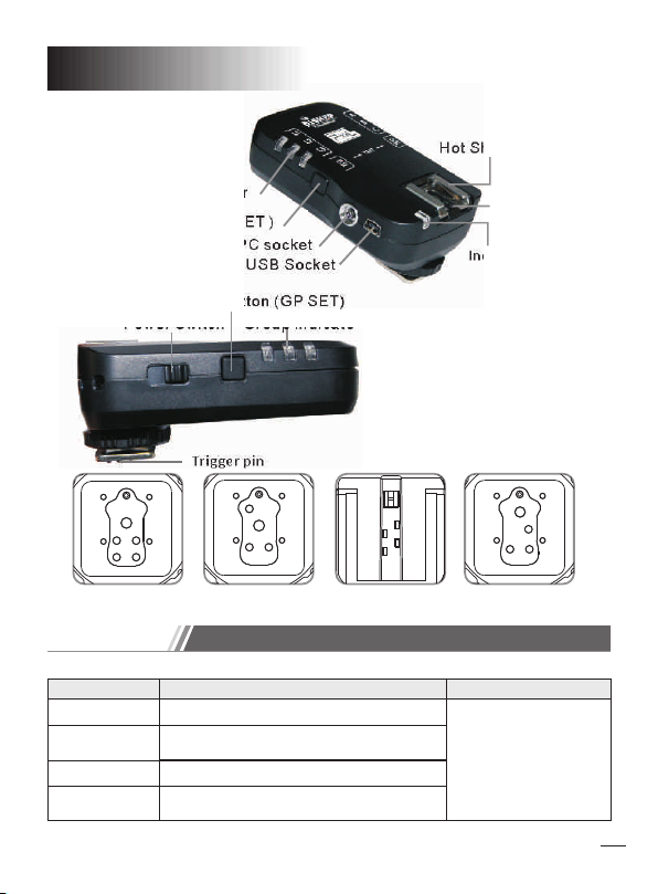
Receiver
Channe l Ind icator
Channe l but ton (CH SET )
Output P C soc ket
Group se t but ton (GP SET )
Power Sw itc h
US B Socke t
Group In dic ate
Product Manual
Digital Flash Trigger
Hot Shoe S tan d
Trig ger pi n
Indica tor
1
Page 2
Transmitter
Hot Shoe S tan d
Channe l Ind icator
Channe l but ton (CH SET )
Input/ Out put PC sock et
USB Sock et
Ind icator
Group se t but ton (GP SET )
Power Sw itc h
F ON
F
O
Group In dic ate
Trig ger pi n
for Canon for Nikon for Sony for Olympus/
Panasonic
Compatible
BISHOP model compatible list as below:
Mo del
For C anon
For N ikon
For Sony
for O lympus/
Panasonic
Nik on seri es came ra, Sam sung se ries ca mera,
Fuj ifilm s eries c amera , Pante x serie s camer a
Son y serie s camer a, Mino lta ser ies cam era
Above br and n ame is regi ste red by the re spectiv e own er.
Transmitter Receiver
Can on seri es came ra
Oly mpus/ Panas onic se ries ca mera
Qri ginal s peedl ite,
stu dio lig ht,Me tz,
SUN PAK, Sigma
Trig ger pi n
2
Page 3

Overview
Thank you so much f or p urc has ing PI XEL product, BISHOP i s a
professiona l gro upi ng fl ash t rigger. TTL mode av ail abl e on tr ansmitter
hot sh oe and sync wi th off shoe trigger t oge the r. Off shoe trigger ca n
be grouped th e fl ash and shu tte r th e ca mer a. B ISH OP i s us ing glo bal
free FSK 2.4GHz w hic h is mo re st abi liz e.
Cautions before use
1. Make sure the ca mer a is po wer ed off before inst all d evi ce.
2. This is electronic products accessories; one o f the e nvi ron men t
causes may affect the working. However this is hard ly ev er to g et
this situation, do n't w orr y!
3. This component can't be strong vibration, or may l ead t o pro duc t
failure.
4. For a long time no n-u se, p lea se tu rne d off the trans mit ter a nd th e
receiver's po wer a nd re mov e the b att ery.
5.The batteri es sh oul d not i nst all a nti -po lar ity; otherwise the
batteries may l eak . cor ros ive l iqu ids , hea t or ex plosion.
6. When the produ ct co nne cte d to th e dev ice , Do no t pul l the wires.
7. Do not put it in hig h tem per atu re, s uch a s a clo sed c ar un der direct
sunlight, the cont rol p ane l and o the r hig h-t emp erature areas.
8. keep dry, do not use wet hand contact with te product, th e pro duc t
must not be immer sed i n wat er or e xpo sed t o rai n, an d thi s may lead
to not work prope rly.
9. Do not use flamm abl e gas es in v iol ati on of t his w arn ing may cause
an explosion or f ire .
10.Because of t his p rod uct i s inc lud ed ba tte ry; p lease strictly follow
the instruction fo r ope rat ion . Oth erw ise i ts ma y cause an
explosion, fi re or p ers ona l inj ury .
Feature
1.BISHOP is a professional grouping flash trigg er
2.Tran smi tte r hot s hoe support TTL and sync with off shoe flash.
3.Wake -up f unc tion available, the flash will be wake up automatically.
4.Through stu dio l igh t to co nne ct PC o r USB s ock et, t he sync speed
up to 1/320s(
camera model
5. Available to control the shooting or through m ast er ca mer a to
control slave c ame ra.
Sync time may hav e lit tle b it in acu rra cy as d iffere nce
).
.
3
Page 4
Specification
Wireless Frequency System
Operating Distance up to 200m
:
Shutter Sync Speed:
Group setting:
Wireless Channel 7
Operating Time Receiver: 500 hours
:
:
Transmitter: over 20k shoot
Power:
Weight:
Receiver 64.0g ( without battery )
:
FSK2 .4 GHz
1/320s (Depend on camera)
3 difference group (7 combinations)
AA x2 (2.4V~3.2V)
Transmitter 68.5g ( without battery )
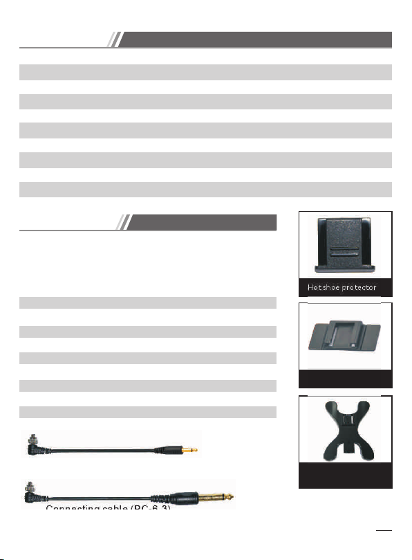
Included item:
Please check the package an d make sure the
below it ems are already in th e box. If there's
mi ss ed a ny th in g, p le as e co nt ac t wi th the
distributor d ire ctl y.
BISHOP Tra nsm itt er 1 pc
BISHOP Receiver 1pc
Connecting ca ble ( PC- 6.3 ) 1pc
Connecting ca ble ( PC- 3.5 ) 1pc
Universal Fla sh Ho lde r(S F-1 8) 1pc
Receiver hold er 1pc
Hot shoe protec tor 2pc
Manual 1p c
Buckle rope 2 pc
Hot s hoe pro tector
Rec eiver ho lder
Connec tin g cable (PC -3.5)
Connec tin g cable (PC -6.3)
Uni versal F lash Ho lder
(SF -18)
4
Page 5

Prepare to use
Battery Insta lla tio n
Receiver and tr ans mit ter a re
the same instal lat ion .
+
AA
-
Turn on power
Tra nsm itt er
ON:
ON
OFF
to on for trigger and
shutter control
Tur n off the
ON
OFF
transmitter
Receiver
AA
ON:
ON
OFF
to on for operating
status
+
OFF:
ON
OFF
receiver
Switch the powe r
OFF:
Switch the powe r
Tur n off the
Channel Setting
Set transmitt er an d rec eiv er to t he sa me ch ann el
1.
Slightly to pre ss “C H SET ” but ton t o sho w the c urr ent ly channel
2.
Press “CH SET” ag ain t o cha nge t he ch ann el.
3.
Changing as:
L1→L2 →L3 →L1,L2→L1,L 3→L2, L3→L1 ,L2 ,L3→L 1→
CH
SET
CH
SET
CH
SET
CH
SET
CH
SET
CH
SET
CH
SET
4. Press “CH SET” for 2 sec a gai n or le ave t he bu tto n for 4 sec,
Group display l igh t tur n off at that time.
CH
SET
Trans mitte r
* Transmi tte r and recei ver must be set as t he same cha nne l.
*Tr ansmitt er ha s memoriz e functio n whi ch saved yo u las t setting a s diff ere nce
group.
CH
SET
Rec eiver
CH
SET
Trans mitte r
CH
SET
Rec eiver
CH
SET
Trans mitte r
CH
SET
Rec eiver
CH
SET
5
Page 6

Group setting
Group setting on tra nsm itt er
1.
Slightly to pre ss “G P SET” button to show the current ly gr oup .
2. Press “GP SET” again to change the group.
3.
Group changin g as:
A →B →C→A、B →A、C→B、C→A、B、C→A→
GP
SET
GP
SET
GP
SET
GP
SET
GP
SET
GP
SET
GP
SET
GP
SET
4.Press “GP SET” for 2sec again or leave the button for 4s ec,
Group display l igh t tur n off at that time.
* When A,B, C ind icator li ght is on mean the t ransmit ter i s synchro nizing th e
receiv er.
Group setting on receive r
Slightly to pre ss “G P SET” button to show the current ly gr oup .1.
2.
Press “GP SET” again to change the group.
3.
Group transmitting order:
A→B→C→A→
GP
SET
GP
SET
GP
SET
GP
SET
4.Press “G P SET ”fo r 2sec again o r lea ve the button f or 4sec,
Group display l igh t tur n off at that time.
* Receiv er on ly get sign al fr om transm itter whe n the c urrent gr oup
settin g of re ceiver is i ncluded in the v alidate g rou p of transm itter.
Testing:
Check power on or o ff.
1.
Check the channel of transmi tter a nd rec eive r.
2.
Check the group s ett ing o f tra nsm itt er an d rec eiv er.
3.
Testing the recei ver s ign al as b elo w:
6
Page 7

GP
+
+
+
CH
SET
SET
ON
OFF
ON
OFF
1. Ins ert fla shg un o n t he
rec eive r and tur n on the
fl ash p owe r; se t the
fla sh index as m inim um.
2. Pr ess the button CH SET
and GP SE at th e same t ime.
Device Conne ction
Tig ht th e Hot shoe with screw, a nd th en
1.
turn right to rela x.
Plug the transmi tte r on th e camera hot shoe.
2.
Tig ht th e Hot shoe with screw, a nd th en
3.
turn left to lock.
Connect the Transmitter to Hot Shoe
(1 (2
1.Plug the PC cord i nto
transmitter PC s ock et.
2.Plug the PC cord to
camera PC socket .
( )Trans mitte r
Connect the Transmitter to Camera via PC cable.
*PC-PC c abl e should be p urc hased sep arately .
3. Tr igge r the Fl ash.
7
Page 8

1. Split the protection film on the receiver holder
2
31
and stick it on the sturio light as figure.
2. Fix the Receiver on the Receiver holder.
3. According to use the PC-3.5 or PC-6.3 on the
studio light socket.
4.Insert PC plug into receiver PC output socket.
5. Insert other plug into the socket of Studio Light.
Connect the Receiv er to St udio Light
1.
Unlock the Speed lit e Fla sh locking screw
2.
Insert the Speed lit e Fla sh into the receiver
hot shoe socket as f igu re.
3.
According to the f las h loc king method to
lock the speedli te on r ece iver.
Connect the Rec eiv er to S pee dli te Fl ash
1. Plug the USB shutter cable
(1 (2
into the USB socket of
Receiver.
2. Plug the shutter control
terminal of USB shutter
USB So cket
able into the control
socket of Camera
Shutter.
*The shu tte r cable sho uld be purchas ed separa tel y.
Connect Recei ver t o Cam era
8
Page 9

Figure Explaination
Off-camera TTL Flash + off-camera flash trigger remote control
By using of the TTL off-camera cable to trigger the off-camera flash
when the Speedl ite TTL fla sh wo rks .
Speedlite fla sh TT L + Studio light off-camera flash
trigger remot e con tro l
Speedlite fla sh TT L + Speedlite flash trigger remote c ont rol
9
Page 10

Speedlite flash TTL + off-camera flash trigger remote control
The transmitter supports th e Speed lit e flash and w ill not hamper
TTL communication of c ame ra. F urt her mor e, it w ill s end t he sync
signal and trig ger t he off-camera flashgun m ean whi le.
Speedlite fla sh TT L + Studio light off-camera flash tr igg er
remote contro l
Speedlite flash TT L + Speedlite flash trigger remote c ont rol
10
Page 11

Off-camera fl ash r emo te co ntr ol
Tra nsm itt er in sta lled on camera hot shoe, and trigger the flash light.
Studio light off-c ame ra fl ash t rig ger r emo te co ntr ol
Speedlite fla sh tr igg er re mot e con tro l
11
Page 12

Transmitter in put /ou tpu t PC so cke t
Transmitter on top TTL, PC sync trigger, off-camera sync trigger.
N
OFF O
Camera on top TTL, PC of f-c ame ra sy nc tr igg er.
12
Page 13

Flash grouping rem ote c ont rol
Receiver A、 B、 C will operate whe n tra nsm itter set at A、 B、 C.
Receiver A、 B wil l ope rate when transmitter set at A、 B.
13
Page 14

Receiver B will o per ate w hen t ran smi tte r set a t B.
Receiver A will operate when transmitter set at A.
14
Page 15

Using under incompatib le mode
When the transmitter is incompatible with the camera, you should
use it as below.
Press TEST bu tto n (Press
“CH SET” and “GP SET”
button in the mea nti me) t o
activate inco mpa tib le mo de.
The using mothe d is sa me
as the compatib le mo de.
* If press button or sh ooting
inte rval time is ove r than
30sec, you have to press
the TEST butt on to set it
agai n, If you don 't pre ss
TES T button, i t may c ause
error si tua tion.
Shooting Control
Remote Shooti ng
GP
CH
SET
SET
Tra nsmitte r
The came ra sh oots dire ctly
Press “CH SET” an d “G P SET” in th e me ant ime to activate the
shooting.
*M ake s ure s et th e len s as MF mode.
15
Page 16

Master camera c ont rol t he sl ave c ame ra
Transmi tte r
Master C ame ra
Receiv er
Slave Ca mer a
Half press release bu tto n of master cam era , th e main-control
camera an d al l remoted cameras will f ocu s, p res s fully, all
cameras will sh oot .
Caution
1. As camera response time is little bit difference, the shooting
time may have a little bit inaccuracy
2. If didn't find the focus, Part of cameras will not shoot even
receiving the shooting signal. At that moment you should change
the focus mode into manual mode “MF”.
3. If not using the specific transmitter, the slave camera cannot
activate focus mode.
Now you can start to use incredible PIXEL product. If you have any
quest io n, you ca n c on tact t he lo cal de al er or vis it to
http://www.pixelhk.com.
This manual information is updated at Dec 10, 2010. If you want to use
this product combined with others, which published after this date;
please consult with the PIXEL dealer for further information.
50143 V 10.0 1
16
 Loading...