

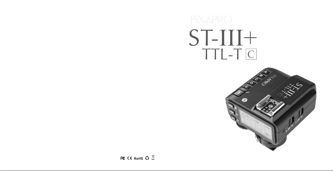
Pixapro ST-III Plus-C, ST-III Plus-F, ST-III Plus-N, ST-III+, TTL-TO Instruction Manual
...Page 1
PIXAPRO® LTD.
50 Popes Lane,
Oldbury,
West Midlands,
B69 4PA
Tel: 0121 552 3113
Web: www.essentialphoto.co.uk
E-mail: info@essentialphoto.co.uk
Company Registration No. 07601334
705-X2TC00-00
Made In China
2.4GHz Wireless Flash Trigger
Instruction Manual
Page 2

Contents
Foreword
02
Warning
03
Names of Parts
04
Body
LCD Panel
Battery
06
Installing Batteries
Battery Level Indication
Setting the Flash Trigger
07
Power Switch
Automatically Enter Power Saving Mode
Power Switch of AF Assist Beam
Channel Settings
Wireless ID Settings
Mode Settings
Output Value Settings
Flash Exposure Compensation Settings
Multi Flash Settings (Output Value, Times
and Frequency)
Modeling Lamp Settings
ZOOM Value Settings
Shutter Sync Settings
Buzz Settings
Foreword
Sync Socket Settings
SHOOT Function Settings
C.Fn: Setting Custom Functions
Using the Flash Trigger
15
As a Wireless Camera Flash Trigger
As a Wireless Outdoor Flash Trigger
As a Wireless Original Flash Trigger
As a Wireless Studio Flash Trigger
As a Wireless Shutter Release Trigger
As a Flash Trigger
with 3.5mm Sync Cord Jack
Connect to Smartphone through Bluetooth
Compatible Smartphone Models
22
Compatible Flash Models
23
Compatible Camera Models
24
Technical Data
25
Restore Factory Settings
26
Firmware Upgrade
26
Attentions
27
Caring for Flash Trigger
28
- 01 - - 02 -
Thanks for your purchase of this ST-III Plus-C wireless flash trigger.
This wireless flash trigger is suitable for using Canon cameras to control PIXAPRO
flashes with ONE System e.g. camera flash, outdoor flash, and studio flash. It can
also control Canon original speedlites with the coordination of ST-III R-C receiver.
Featuring multi-channel triggering, stable signal transmission, and sensitive
reaction, it gives photographers unparalleled flexibility and control over their strobist
setups. The flash trigger applies to hotshoe-mounted Canon EOS series cameras,
as well as the cameras which have PC sync sockets.
With ST-III Plus-C wireless flash trigger, high speed synchronization is available for
most of camera flashes in the market which support E-TTL
synchronization speed is up to 1/8000s *.
*: 1/8000s is achievable when the camera has a max camera shutter speed of 1/8000s.
II. The max flash
Page 3
Warning
Names of Parts
Do not disassemble. Should repairs become necessary, this product must be sent to
an authorized maintenance center.
Always keep this product dry. Do not use in rain or in damp conditions.
Keep out of reach of children.
Do not use the flash unit in the presence of flammable gas. In certain circumstance,
please pay attention to the relevant warnings.
Do not leave or store the product if the ambient temperature reads over 50℃.
Turn off the flash trigger immediately in the event of malfunction.
Observe precautions when handling batteries
-
Use only batteries listed in this manual. Do not use old and new batteries or
batteries of different types at the same time.
- Read and follow all warnings and instructions provided by the manufacturer.
- Batteries cannot be short-circuited or disassembled.
- Do not put batteries into a fire or apply direct heat to them.
- Do not attempt to insert batteries upside down or backwards.
- Batteries are prone to leakage when fully discharged. To avoid damage to the
product, be sure to remove batteries when the product is not used for a long time or
when batteries run out of charge.
- Should liquid from the batteries come into contact with skin or clothing, rinse
immediately with fresh water
.
- 03 - - 04 -
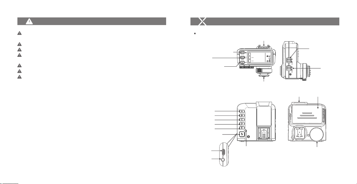
Body
Mode Selection/Locking Button
Menu Button/
Modeling Lamp Control
ALL Settings Selection/
All Selection
Note: All the buttons have backlight, which is convenient
for usage in dark environment.
Group Button A
Group Button B
Group Button C
Group Button D
Group Button E
TEST/Shutter Button
Type-C USB
Port
3.5mm Sync
Cord Jack
Hot Shoe Speedlite Connection
1/128
M
A
B
C
Hot Shoe Camera Connection
Status Indicator Lamp
--Green:
Trigger (Flash) + Focus (Camera)
--Red:
Trigger (Flash) + Shutter (Camera)
AF Assist Beam Switch
CH 01
--ON (AF Assist Beam outputs)
AF-assist Lamp
--OFF (A F Assist Beam
do not output)
Power Switch
--ON (Power On)
--OFF (Power Off)
Battery Compartment
Select Dial
Page 4
Names of Parts
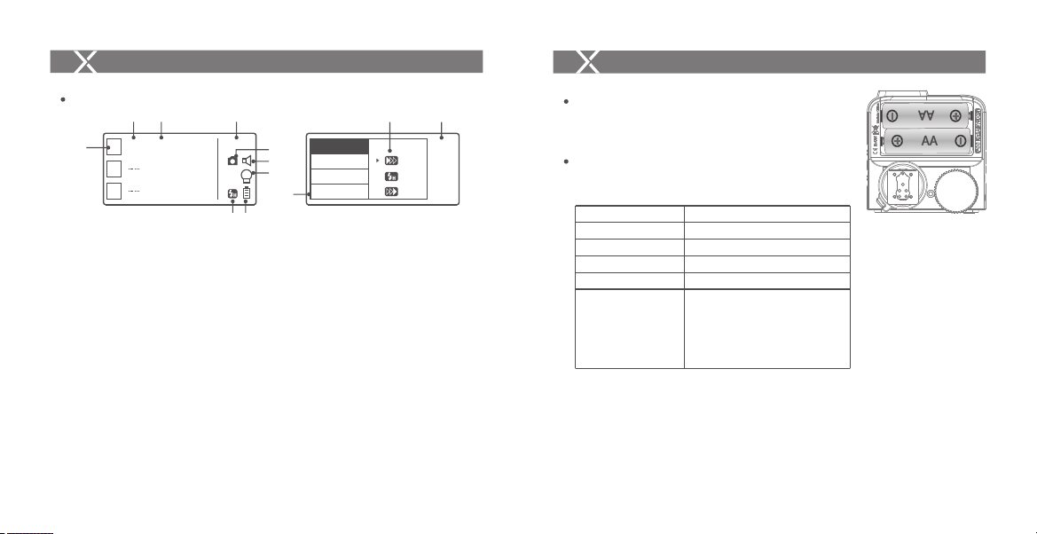
LCD Panel
7
1. Channel (32) 2. Camera Connection 3. Modeling Lamp Master Control
4. High-Speed/Rear Curtain Sync 5. Sound 6. Battery Level Indication
7. Group 8. Mode 9. Power 10. ZOO M Value 11. Version
8
M
A
B
C
9
1/128
Group Display
1
2
CH 01
5
3
6
4
- 05 - - 06 -
SYNC
BLUE.T.
BEEP
ZOOM
10
Menu
V0.2
1/4
Battery
AA alkaline batteries are recommended.
114
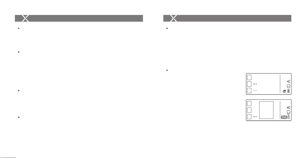
Installing Batteries
As shown in the illustration, slide the battery
compartment lid of the flash trigger and insert two
AA batteries separately.
Battery Indication
Check the battery level indication on the LCD panel
to see the remaining battery level during the usage.
Battery Level Indication
3 grids
2 grids
1 grid
Blank grid
Blinking
The battery indication only refers to AA alkaline batteries. As the voltage of Ni-MH battery tends to be
low, please do not refer to this chart.
Meaning
Full
Middle
Low
Low battery, please replace it.
< 2.5V The battery level is going
to be used out immediately (please
replace new batteries, as low power
leads to no flash or flash missing in
case of long distance).
Page 5
Setting the Flash Trigger
Setting the Flash Trigger
Power Switch
Slide the Power Switch to ON, and the device is on and status indicator lamp will not
reveal.
Note: In order to avoid power consumption, turn off the transmitter when not in use.
Automatically Enter Power Saving Mode
1. The system will automatically enter standby mode after stop operating the
transmitter over 60 seconds. And the displays on the LCD panel disappear now.
2. Press any button to wake up. If the flash trigger is attached to the hot shoe of
CANO N EO S camera, half press the camera shutter can also wake the system up.
Note: If do not want to enter power saving mode, press the <MENU > button to enter C.Fn custom
settings and set STBY to OFF.
Power Switch of AF Assist Beam
Slide the AF-assist beam switch to ON, and the AF lighting is allowed to output.
When the camera cannot focus, the AF assist beam will turn on; when the camera can
focus, the AF assist beam will turn off.
Channel Setting
1. Short press the <MENU> button and choose CH to set the channel value.
2. Turn the select dial to choose the appropriate channel. The channel value will be
confirmed after exiting the menu.
3. This flash trigger contains 32 channels which can be changed from 1 to 32. Set
the transmitter and the receiver to the same channel before usage.
- 07 -
Wireless ID Settings
Change the wireless channels and wireless ID to avoid interference for it can only be
triggered after the wireless IDs and channels of the master unit and the slave unit are
set to the same.
Press the <MEN U> button to enter C.Fn ID. Press the <S ET> button to choose O FF
channel expansion shutdown, and choose any figure from 01 to 99.
Note: It can only be used when the slave units have the wireless ID settings functions. If they do not
have, please set the ID to OF F.
Mode Setting
1. After pressing the group button to select one
group, press the <MOD E> button and all the current
group’s mode will be changed by the order of
TTL/M/--.
2. In normal situation, press the <MOD E> button to
switch the multi-group mode to MULTI mode. Press
the group selection button and then press the
<MOD E> buttoncan set the MULTI mode to ON or
OFF.
- 08 -
1/128
M
A
B
C
1/128
ON
A
1Hz
ON
B
C
1Times
CH 01
CH 01
Page 6
Setting the Flash Trigger
Setting the Flash Trigger
Output Value Settings
In the M mode
1 . Press the group button to choose the group, turn the select dial, and the power
output value will change from Min to 1/1 in 0.3 stop increments. Press the <SET>
button to confirm the setting.
2. Press <ALL> button to choose all groups’ power output value, turn the select dial,
and all groups’ power output value will change from Min to 1/1 in 0.3 stop
increments. Press <ALL> button again to confirm the setting.
Note: Min. refers to the minimum value that can be set in M or Multi mode. The minimum value can be
set to 1/128 0.3, 1/256 0.3, 1/128 0.1, 1/256 0.1, 3.0(0.1) and 2.0(0.1) according to C.Fn-Min.
For most of camera flashes, the minimum output value is 1/128 and cannot be set to 1/256. However,
the value can change to 1/256 when using in combination with PIXAPRO strong power flashes e.g.
AD600, etc.
Flash Exposure Compensation Settings
In the TTL mode
Press the group button to choose the group, turn the select dial, and the FEC value will
change from -3 to ~3 in 0.3 stop increments. Press the <SET> button to confirm the
setting.
Multi Flash Settings (Output Value, Times and Frequency)
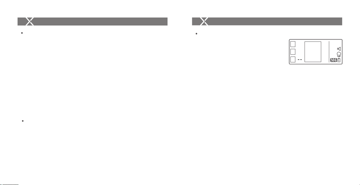
1. In the multi flash (TTL and M icon are not
displayed).
2. The three lines are separately displayed as power
output value, Hz(flash frequency) and Times(flash
times).
3. Press the <SET> button and turn the Select Dial to
change the power output value from Min. to 1/4 in
integer stops.
4. Press the <SET> button again and choose Hz to
change flash frequency. Turn the select dial to
change the setting value.
5. Press the <SET> button again and choose Times to
change flash times. Turn the select dial to change
the setting value.
6. Until all the amounts are set. Or during any value
setting, short press the <SET> button to exit the
setting status.
7. In the multi flash setting submenu, short press the
<MOD E> button to return to main menu when no
values are blinking.
Note: As flash times are restricted by flash output value and flash frequency, the flash times cannot
surpass the upper value that permitted by the system. The times that transported to the receiver end are
a real flash time, which is also related to the camera’s shutter setting.
- 10 -- 09 -
1/128
ON
A
1Hz
ON
B
C
1Times
CH 01
Page 7
Setting the Flash Trigger
Setting the Flash Trigger
Modeling Lamp Settings
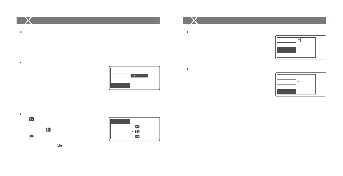
1. Long press the <MEN U> button for 2 seconds to
control the ON/O FF of the modeling lamp.
ZOOM Value Settings
Short press the <MEN U> button to enter the ZOO M
menu. Short press the <SET> button and turn the
select dial, and the ZOO M value will change from
AUTO/24 to 200. Choose the desired value and back
to the main menu.
Note: The flash’s ZOOM should be set to Auto (A) mode before
responding.
Shutter Sync Settings
1. High-speed sync: short press the <MENU>
button to enter the SYNC menu. Choose high-speed
sync icon and is displayed on the LCD panel.
2. Second-curtain sync: short press the <MENU>
button to enter the SYNC menu. Choose second-
curtain sync icon and is displayed on the LCD
panel.
- 11 -
SYNC
BLUE.T.
BEEP
ZOOM
SYNC
BLUE.T.
BEEP
ZOOM
24
V0.2
1/4
V0.2
1/4
Buzz Settings
Press the <MEN U> button to enter C.Fn BEE P and
press the <SET> button. Choose ON to turn on the
BEEP while OFF to turn off it. Press the <M ENU>
button again to back to the main menu.
Sync Socket Settings
1. Press the <MEN U> button to enter C.Fn SYN C
and press the <SET> button to choose IN or OU T.
Press the <MEN U> button again to back to the
main menu.
When choosing IN, this sync socket will
1.1
enable ST-III Plus C to trigger flash.
1.2 When choosing OUT, this sync socket will
send trigger signals to trigger other remote
control and flash.
- 12 -
SYNC
BLUE.T.
BEEP
ZOOM
SCAN
CH
ID
PC SYNC
OFF
ON
IN
OUT
V0.2
1/4
V0.2
2/4
Page 8
Setting the Flash Trigger
Setting the Flash Trigger
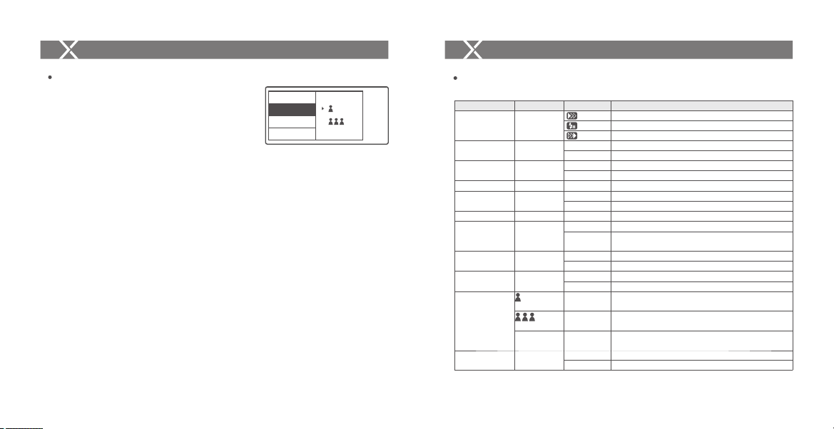
SHOOT Function Settings
Press the <MEN U> button to enter C.Fn SHO OT.
Press the <SET> button to choose one-shoot or multi-
shoots, and press the <MEN U> button again to back
to the main menu.
One-shoot: When shooting, choose one-shoot. In the
M and Multi mode, the master unit only sends
triggering signals to the slave unit, which is suitable
for one person photography for the advantage of
power saving.
Multi-shoots: When shooting, choose multi-shoots,
and the master unit will send parameters and
triggering signals to the slave unit, which is suitable
for multi person photography. However, this
function consumes power quickly.
APP: Only send triggering signal when camera is
shooting (control the flash's parameters by
smartphone APP).
DELAY
SHOOT
DIST
STEP
APP
V0.2
3/4
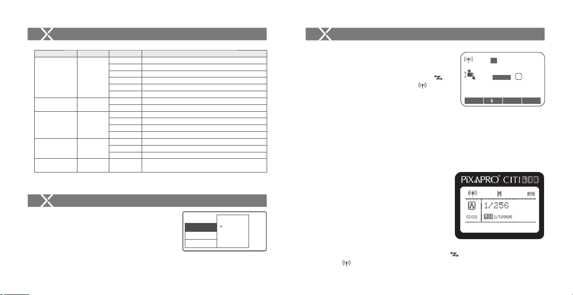
C.Fn: Setting Custom Functions
The following table lists the available and unavailable custom functions of this flash.
Custom Function
SYNC
BLUE.T.
BEEP
ZOOM
SCAN
CH
ID
PC SYNC
DELAY
SHOOT
DIST
Function
Shutter sync
setting
Bluetooth
status setting
Beeper
ZOOM setting
Scan the spare
channel
Wireless
Channel setting
Wireless ID
Sync cord jack
Delay setting
APP
Triggering
distance
Setting Signs
OFF
ON
ON
OFF
24
OFF
START
01
OFF
01-99
IN
OUT
OFF
0.1ms-9.9ms
One-shoot
All-shoot
APP
0-30m
1-100m
Settings and Description
Front curtain
High speed
Second curtain
Off
On
On
Off
AUTO/24-200
Off
Start to find the spare channel
01-32
Off
Choose any figure from 01-99 (the old version
flashes cannot use this function temporarily)
Trigger ST-III Plus-C to fire flash
Output signal to trigger other remote control and flash
Off
Set the firing delay in high-speed sync
Only send triggering signals in the M & Multi mode when
camera is shooting
Send parameters and triggering signal when camera is
shooting(suitable for multi person photography)
Only send triggering signal when camera is shooting
(control the flash’s parameters by smartphone APP)
0-30m triggering
1-100m triggering
- 14 -- 13 -
Page 9
Setting the Flash Trigger
Using the Flash Trigger
Custom Function
STEP
GROUP
STBY
LIGHT
LCD
Function
Power output
value
Group
Sleep
Backlighting
time
Contrast ratio
of LCD panel
Setting Signs
1/128(0.3)
1/256(0.3)
1/128(0.1)
1/256(0.1)
3.0(0.1)
2.0(0.1)
5 (A-E)
3 (A-C)
60sec
30min
60min
OFF
12sec
OFF
ON
-3-+3
Using the Flash Trigger
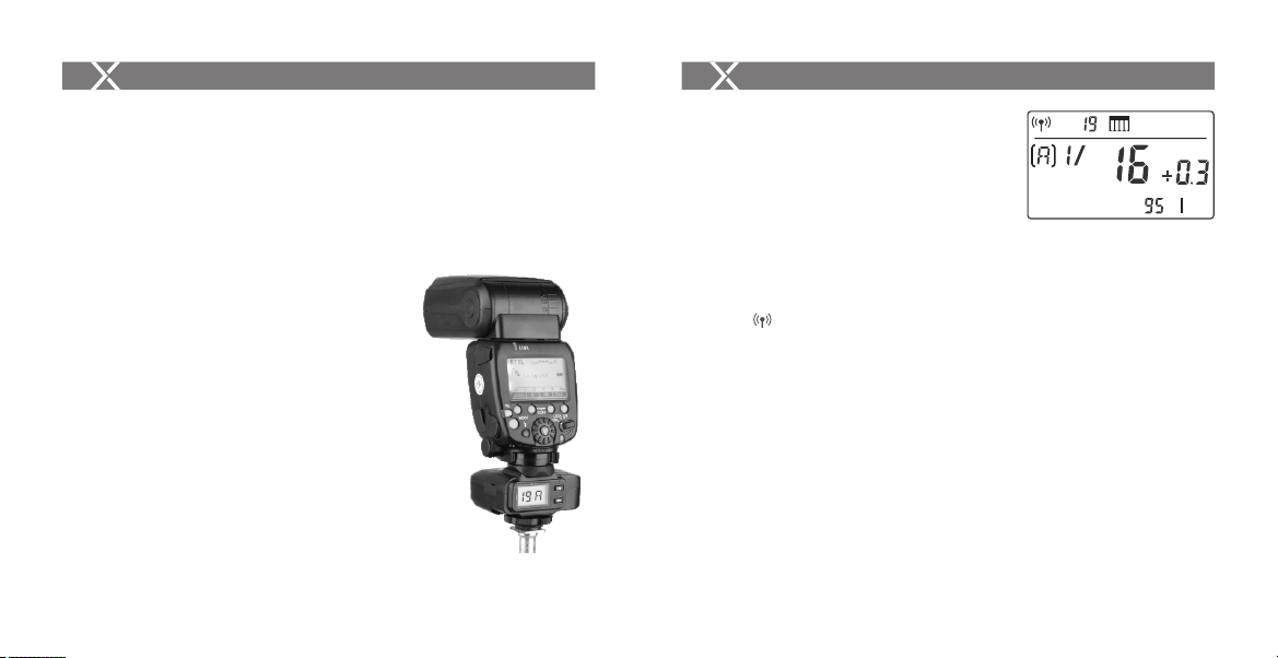
1. As a Wireless Camera Flash Trigger
Take Li-ion580II as an example:
1.1 Turn off the camera and mount the
transmitter on camera hotshoe. Then, power on
the flash trigger and the camera.
- 15 -
Settings and Description
The minimum output is 1/128(change in 0.3 step)
The minimum output is 1/256(change in 0.3 step)
The minimum output is 1/128(change in 0.1 step)
The minimum output is 1/256(change in 0.1 step)
The minimum output is 3.0(change in 0.1 step)
The minimum output is 2.0(change in 0.1 step)
5 groups(A/B/C/D/E)
3 groups(A/B/C)
60 seconds
30 minutes
60 minutes
-Auto off in 12 seconds
Always off
Always lighting
The contrast ration can be set as integral number from
-3 to +3
SCAN
CH
19
ID
PC SYNC
V0.2
2/4
1.2 Short press the <MEN U> button to set channel,
group, mode and parameters (refers to the
contents of “Setting the Flash Trigger”).
1.3 Turn on the camera flash, press the
wireless setting button and the wireless
icon and <SLAVE> slave unit icon will be
displayed on the LCD panel. Press the < CH>
button to set the same channel to the flash
trigger, and press the <Gr> button to set the
same group to the flash trigger (Note: please refer
to the relevant instruction manual when setting the
camera flashes of other models).
1.4 Press the camera shutter to trigger and the
status lamp of the flash trigger turns red synchronously.
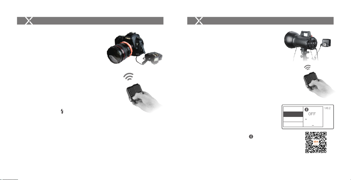
2. As a Wireless Outdoor Flash Trigger
Take CITI600 Manual as an example:
2.1 Turn off the camera and mount the
transmitter on camera hotshoe. Then,
power on the flash trigger and the
camera.
2.2 Short press the <MEN U> button to set
channel, group, mode and parameters
(refers to the contents of “Setting the
Flash Trigger”).
2.3 Power on the outdoor flash and press the wireless setting button and the
wireless icon will be displayed on the LCD panel. Long press the
< >
< >
- 16 -
< >
M
CH19
Zm/C.Fn Gr CH
< >
M
SLAVE
±
Zoom
24
1/128
mm
A
Page 10
Using the Flash Trigger
Using the Flash Trigger
<GR/C H> button to set the same channel to the flash trigger, and short press
the < GR/C H> button to set the same group to the flash trigger (Note: please
refer to the relevant instruction manual when setting the oudoor flashes of other
models).
2.4 Press the camera shutter to trigger and the status lamp of the flash trigger turns
red synchronously.
3. As a Wireless Original Flash Trigger
Take 600EX-RT as an example:
3.1 Turn off the camera and mount the transmitter
on camera hotshoe. Then, power on the flash
trigger and the camera.
3.2 Short press the <MEN U> button to set channel,
group, mode and parameters (refers to the
contents of “Setting the Flash Trigger”).
3.3 Attach the original flash to the ST-III R-C receiver.
Press the <CH> button on the receiver to set
the same channel to the flash trigger, and press
the <Gr> button to set the same group to the
flash trigger (Note: please refer to the relevant
instruction manual when setting the original
camera flashes).
3.4 Press the camera shutter to trigger. And the
status lamp of the camera flash and the flash
trigger both turn red synchronously.
GRCH
4. As a Wireless Studio Flash Trigger
Take LUMI400II as an example:
4.1 Turn off the camera and mount the transmitter
on camera hotshoe. Then, power on the flash
trigger and the camera.
4.2 Short press the <MEN U> button to set
channel, group, mode and parameters (refers
to the contents of “Setting the Flash Trigger”).
4.3 Connect the studio flash to power source and
power it on. Synchronously press down the
<GR/C H> button and <S1/S2>button and the
wireless icon will be displayed on the
< >
LCD panel. Long press the <G R/CH> button to
set the same channel to the flash trigger, and
short press the < GR/C H > button to set the
same group to the flash trigger (Note: please
refer to the relevant instruction manual when
setting the studio flashes of other models).
4.4 Press the camera shutter to trigger. And the
status lamp of the camera flash and the flash
trigger both turn red synchronously.
Note: As the studio flash’s minimum output value is
1/32, the output value of the flash trigger should
be set to or over 1/32. As the studio flash do not
have TTL and stroboscopic functions, the flash
trigger should be set to M mode in triggering.
- 18 -- 17 -
CH
%
Page 11
Using the Flash Trigger
Using the Flash Trigger
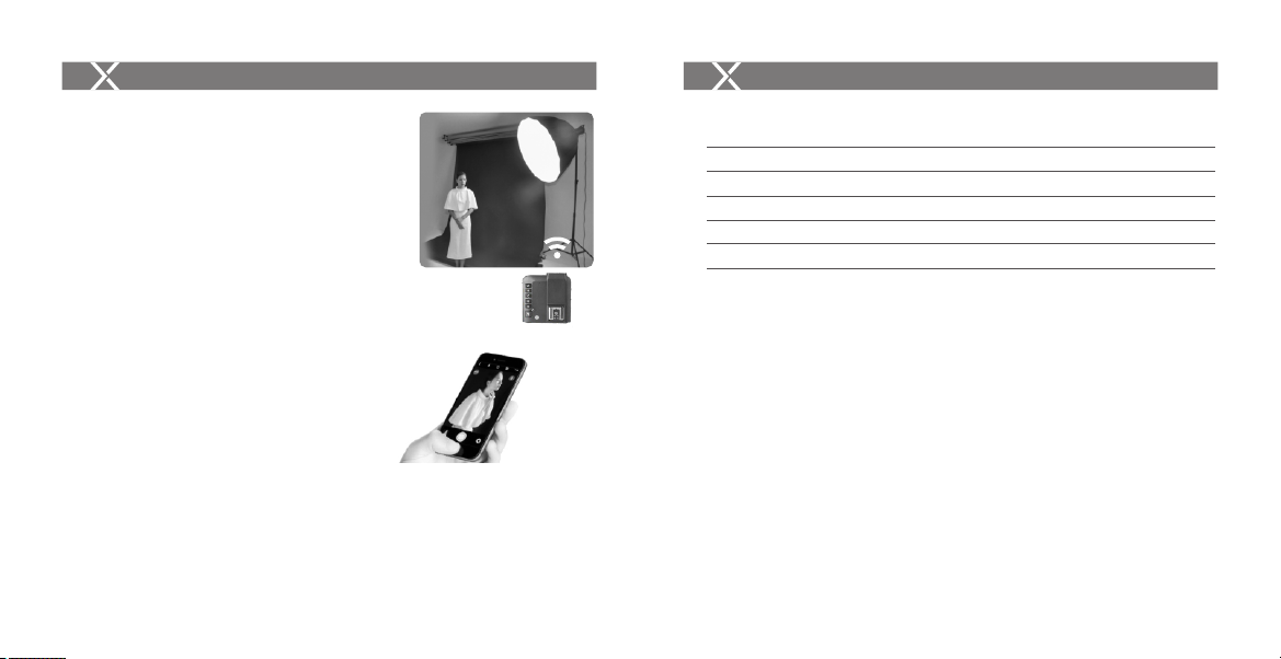
5. As a Wireless Shutter Release Trigger
Operation method:
5.1 Turn off the camera. Take a camera remote
cable and insert one end into the camera’s
shutter socket and the other end to the
shutter release port of ST-III R-C to connect.
Power on the camera and the receiver.
5.2 Short press the <MEN U> button to set
channel, group, mode and parameters
(refers to the contents of “Setting the Flash
T
rigger”).
5.3 Press the receiver’s <CH> button to set the
same channel to the flash trigger, and press
the <Gr> button to set the same group to the
flash trigger.
5.4 Half press the button to focus and full
press the <TES T> button to shoot. Release
the button until the status lamp turns to red.
6. As a Flash Trigger with 3.5mm Sync Cord Jack
Operation method:
6.1 The connection method please refers to the
contents of “As a Wireless Studio Flash Trigger”
and “As a Wireless Shutter Release”.
6.2 Set the transmitter end’s sync cord jack as an
output port. Operation: press the <MEN U>
button on the transmitter end to enter C.Fn
settings. Then, set PC SY NC to O UT mode.
6.3 Press the shutter normally and the flashes will
be controlled by sync cord jack's signal.
7. Connect to Smartphone through Bluetooth
Using method:
7.1 Short press the <MENU> Button to enter
BLUE.T. to open the Bluetooth. The Bluetooth ID
will displayed under the ON.
7.2 Search“Godox Photo”in iPhone’s APP Store
and download the APP. Or install the APP by
scanning the QR Code with your smartphone.
Open the APP and choose .
7.3
7.4 Connect the transmitter to the responded
Bluetooth ID and enter the password to
match
(the initial password is “000000”).
- 20 -- 19 -
SYNC
BLUE.T.
BEEP
ZOOM
OFF
ON
GDBHA7BC
"GodoxPhoto"
V0.2
1/4
Page 12
Using the Flash Trigger
7.5 Full match and back to APP main interface.
7.6 When started the Bluetooth function, the
Bluetooth icon will be displayed on the
transmitter’s panel.
7.7 Set the channels of the slave flash and the
transmitter to the same, and parameters e.g.
slave flash mode, power value, modeling lamp
and beep can be controlled on the APP of the
smartphone.
7.8 Use the APP of the smartphone for shooting
after setting all the parameters.
Note: When successfully connected the flash trigger and
smartphone APP, the auto sleep of the flash trigger can be
set to 30 min.
Compatible Smartphone Models
This flash trigger can be used on the following Smartphone models:
iPhone 6S iPhone 6S Plus iPhone 7 Plus iPhone 7 iPhone 8 Plus
iPhone 8 iPhone 6 Plus iPhone 6 iPhone X
HUAWEI P9 HUAWEI P10 HUAWEI P10 Plus HUAWEI Mate 9 Pro
HUAWEI Mate 9 HUAWEI Mate 10 Pro HUAWEI Mate 10
HUAWEI P20 HUAWEI P20 Pro
Samsung galaxy S8 Samsung galaxy Note8 Samsung galaxy S9
1. This table only lists the tested Smartphone models, not all Smartphone. For the compatibility
of other Smartphone models, a self-test is recommended.
2. Rights to modify this table are retained.
- 21 -
- 22 -
Page 13
Compatible Flash Models
Compatible Flash Models
Compatible Flash Models
Receiver
Transmitter
ST-III
Plus C
Note: The range of support functions: the functions that are both owned by ST-III Plus-C and flash.
Flash
-
CITI600 series/CITI400 series
Hybrid360 TTL series PIKA200 series
Li-ion580II series/Li-ion350II Series/
STORM II/ LUMI II KINO II+ series
600EX-RT/ 580EXII / 580EX / 430EXII
ST-III
R-C
Li-ion580 ETTL
PRO AC
HYBRID360 Manual, RIKO400
2.4GHz
STORM / KINO / LUMI Series
ST-I
Li-ion580 ETTL / Li-ion580 ITTL
2.4GHz
Li-ion580 Manual
- 23 -
Note
As there are so many camera flashes in
the market which are compatible with
Canon speedlites, we do not test one by one.
The flashes with wireless USB port
Can only be triggered
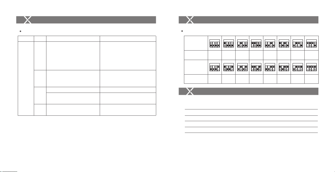
The relationship of PRO AC wireless system andST-III + wireless system:
ON
PRO AC 2.4
(Code Switch)
ST-III +
(Display Screen)
PRO AC 2.4
(Code Switch)
ST-III +
(Display Screen)
ON ON ON ON ON ON ON
CH01 CH02 CH03 CH04 CH05 CH06 CH07 CH08
ON ON ON ON ON ON ON ON
CH09 CH10 CH11 CH12 CH13 CH14 CH15 CH16
Compatible Camera Models
This flash trigger can be used on the following Canon EOS series camera models:
1DX Mark II 1DX 5Ds/5Dsr 5DⅣ 5D Mark III 5D Mark II 5D
7D Mark II 7D 6D 80D 70D 60D 50D 6D MarkII 77D 800D
40D 30D 750D/760D 700D 650D 600D 550D500D 450D 400D
Digital350D DIGITAL100D 1200D 1000D 1100D M5 M3 EOS R
M50 1500D(2000D/T7) 3000D(4000D)
1. This table only lists the tested camera models, not all Canon EOS series cameras. For the compatibility
of other camera models, a self-test is recommended.
2. Rights to modify this table are retained.
3. The cameras which are released before 2012 do not have TTL mode in their D and E group.
4. 1500D(2000D/T7), 3000D(4000D):When the high-speed shutter is higher than 1000, there will be
lunimance edge on the photo.
- 34 -
Page 14
Technical Data
Technical Data
Model
Compatible cameras
Compatible smartphone
(sync flash in M mode)
Power supply
Flash Exposure Control
TTL autoflash
Manual flash
Stroboscopic flash
Function
High-speed sync
Flash exposure
compensation
Flash exposure lock
Focus assist
Modeling lamp
Beeper
Wireless shutter
ZOOM setting
TCM function
Firmware upgrade
Memory function
ST-III Plus-C
Canon EOS cameras (E-TTL II autoflash)
Support for the cameras that have PC sync socket.
iphone, Huawei, Samsung(see the compatible smartphone models for details)
2*AA batteries
E-TTL II
Yes
Yes
Yes
Yes, ±3 stops in 1/3 stop increments
Yes
Yes
Yes
Yes
Control the beeper by the flash trigger The receiver end can control the
camera shooting through the 3.5mm sync cord jack
Adjust the ZOOM value by the transmitter
Transform the TTL shooting value into the output value in the M mode
Upgrade through the Type-C USB port
Settings will be stored 2 seconds after last operation and recover
after a restart
- 25 -
Model
Wireless Flash
Transmission range (approx.)
Built-in wireless
Modulation mode
Channel
Wireless ID
Group
Other
Display
Dimension/Weight
2.4G Wireless Frequency Range
Max. Transmitting Power of 2.4G Wireless
Restore Factory Settings
Hold the MOD E button and power the flash trigger on, and all the parameters will
restore the factory settings.
ST-III Plus-C
0-100m
2.4G
MSK
32
01-99
5
Large LCD panel, backlighting O N or OFF
72x70x58mm/90g
2413.0MHz-2463.5MH z
5dbm
Firmware Upgrade
This flash trigger supports firmware upgrade through the Type-CUSB port. Update
information will be released on our official website.
USB connection line is not included in this product. As the USB port is a Type-C
USB
socket, please use Type-C USB connection line.
As the firmware upgrade needs the support of PIXAPRO G3 software, please
download and install the "PIXAPRO G3 firmware upgrade software" before
upgrading. Then, choose the related firmware file.
- 26 -
Page 15

Attentions
1. Unable to trigger flash or camera shutter. Make sure batteries are installed
correctly and Power Switch is turned on. Check if the transmitter and the receiver
are set to the same channel, if the hotshoe mount or connection cable is well
connected, or if the flash triggers are set to the correct mode.
2. Camera shoots but does not focus. Check if the focus mode of the camera or lens
is set to M
3. Signal disturbance or shooting interference. Change a different channel on the
4. Operating distance limited or flash missing. Check if batteries are exhausted. If so,
F. If so, set it to AF.
device.
change them.
The Reason & Solution of Not Triggering in PIXAPRO 2.4G Wireless
1. Disturbed by the 2.4G signal in outer environment (e.g. wireless base
station, 2.4G wifi router, Bluetooth, etc.)
→ To adjust the channel CH setting on the flash trigger (add 10+ channels) and
use the channel which is not disturbed. Or turn off the other 2.4G equipment in
working.
2. Please make sure that whether the flash has finished its recycle or caught up
with the continuous shooting speed or not(the flash ready indicator is
lighten) and the flash is not under the state of over-heat protection or other
abnormal situation.
→ Please downgrade the flash power output. If the flash is in TTL mode, please try
to change it to M mode(a preflash is needed in TTL mode).
3. Whether the distance between the flash trigger and the flash is too close or
not
→ Please turn on the “close distance wireless mode” on the flash trigger (<0.5m):
→ Please set the C.Fn-DIST to 0-30m.
- 27 -
4. Whether the flash trigger and the receiver end equipment are in the low
battery states or not
→ Please replace the battery(the flash trigger is recommended to use 1.5V
disposable alkaline battery).
Caring for Flash Trigger
Avoid sudden drops. The device may fail to work after strong shocks, impacts, or
excess stress.
Keep dry. The product isn’t water-proof. Malfunction, rust, and corrosion may occur
and go beyond repair if soaked in water or exposed to high humidity.
Avoid sudden temperature changes. Condensation happens if sudden
temperature changes such as the circumstance when taking the transceiver out of a
building with higher temperature to outside in winter. Please put the transceiver in a
handbag or plastic bag beforehand.
Keep away from strong magnetic field. The strong static or magnetic field
produced by devices such as radio transmitters leads to malfunction.
- 28 -
Page 16

FCC Statement
A. This device complies with part 15 of the FCC Rules. Operation is subject to the
following two conditions: (1) This device may not cause harmful interference, and
(2) this device must accept any interference received, including interference that
may cause undesired operation.
B. Warning: Changes or modifications to this unit not expressly approved by the
part responsible for compliance could void the user’s authority to operate the
equipment.
C. NO TE: This equipment has been tested and found to comply with the limits for
a Class B digital device, pursuant to part 15 of the FCC Rules. These limits are
designed to provide reasonable protection against harmful interference in a
residential installation. This equipment generates, uses and can radiate radio
frequency energy and, if not installed and used in accordance with the instructions,
may cause harmful interference to radio communications. However, there is no
guarantee that interference will not occur in a particular installation. If this
equipment does cause harmful interference to radio or television reception, which
can be determined by turning the equipment off and on, the user is encouraged to
try to correct the interference by one or more of the following measures:
- Reorient or relocate the receiving antenna.
- Increase the separation between the equipment and receiver.
- Connect the equipment into an outlet on a circuit different from that to which the
receiver is connected.
- Consult the dealer or an experienced radio/TV technician for help.
- 30 -- 29 -
 Loading...