


UndercoverEye™ Power Box
Instruction Manual
Copyright ©, PixController, Inc. http://www.pixcontroller.com, all rights reserved
1
Revision 1.00B

WARRANTY REGISTRATION
PixController, Inc. warrants products sold by it and guarantees to correct, by repair or
replacement at our option, any defects of material and workmanship which develop under normal
and proper use within twelve (12) months from the date of the original purchase when inspection
proves the fault to be of manufacturing. All such Products must be returned to our service center.
This warranty does not apply to any of our Products which have been repaired or altered by
unauthorized persons or service centers in any way so as, in our judgment, to injure their stability
or reliability, or which have been subject to misuse, negligence, or accident or which have had
their serial number altered, effaced or removed.
We will not assume any expense or liability for repairs made by other parties without our written
consent. PixController, Inc is not responsible for damage to any associated equipment or
apparatus, nor shall we be held liable for loss of profit or other special damages. There is no
other guarantee or warranty except as herein stated.
Returns for any unaffected products are permitted within 14 days from the date of receipt of
merchandise. After such time, items will incur a 15% restocking fee. Returns of wrong ordered
items are allowed. Returned merchandise will be accepted only if all conditions are met.
In no event shall PixController, Inc. be liable for any incidental, special, indirect or consequential
damages, whether resulting from the use, misuse, or inability to use this product or from defects
in this product. The Buyer is not permitted to tamper or remove any of the Raptor System
electronics without voiding this warranty.
The Buyer, his employees, or others assumes all risks and liabilities for the operation, the use
and the misuse of the product described herein and agree to defend and to save the seller
harmless from any and all claims arising from any cause whatsoever, including seller’s
negligence for personal injury incurred in connection with the use of the said product.
PixController, Inc reserves the right to discontinue models at any time or change specifications,
price or design without notice and without incurring any obligation.
The express warranties are in lieu of all other warranties, guarantees, promises, affirmations, or
representations, express or implied which would be deemed applicable to the goods sold
hereunder. No express warranties and no implied warranties, whether of merchantability, fitness
for any particular use or purpose, against infringement, or otherwise (except as to title) other than
those expressly set forth herein, shall apply.
FOR REPAIR CONTACT
PixController, Inc.
1056 Corporate Lane
Export, PA 15632
Phone: 724-733-0970
Fax: 724-733-0860
Email: support@pixcontroller.com
Web : http://www.pixcontroller.com
2

Table of Contents
1. Introduction
2. What’s included with your UndercoverEye™ Power Box System
3. UndercoverEye™ Power Box System Components
4. Setting up the UndercoverEye™ Power Box
5. Powering up the UndercoverEye™ Power Box
6. How to customize the Power Box settings
7. Wireless RF Sensors
7.1 Wireless Sensor Introduction
7.2 Using the Wireless PIR Motion Sensor
8. UndercoverEye™ Power Box 12V Battery & Charger
9. Using your Power Box unit with different 12V devices
3

1. Introduction
The PixController UndercoverEye™ Power Box is a system designed to power 12V devices such
as IR Arrays and/or 12V Wireless Video Transmitter and cameras in conjunction with the
PixController UndercoverEye™ camera systems.
The PixController UndercoverEye™ Power Box was designed to provide remote IR lighting or
turn on a wireless video camera (assuming a video receiver is connected to the PixController
UndercoverEye™ camera system upon trigger from the RF Wireless motion sensor.
The PixController UndercoverEye™ Power Box will give the user the ultimate ability to use the
PixController UndercoverEye™ product series with an unlimited number of configurations
depending on the situation.
The UndercoverEye™ Power Box system utilizes advanced battery savings sleep mode whereby
its passive infrared, wireless motion detector (PIR) automatically switches the UndercoverEye™
system from sleep mode to active mode when someone walks into the target area. This mode will
enable the UndercoverEye™ system to be deployed unattended for long periods of time. The
UndercoverEye™ system also comes with a wireless keyfab option for manually triggering the
base recording unit for various surveillance setups/operations.
The UndercoverEye™ Power Box includes a 16’ cable with (3) 2.1mm 12V center positive
connectors allowing (3) different 12V devices to be connected to the Power Box. One of the 12V
connectors is setup to be powered up only at night via the built in light sensor on the main
UndercoverEye™ Power Box unit. This is the connection made when using a IR array to light the
area only in darkness.
The UndercoverEye™ Power Box can be buried in the ground and video camera placed in a
hidden location for the ultimate covert system. The unit is triggered by PixController Long Range
RF Wireless PIR motion sensor.
4

2. What’s included with your UndercoverEye™ Power Box System
Your UndercoverEye™ Power Box system contains the following items:
• UndercoverEye™ Power Box water proof system case/motion control electronic
• Removable Tilt-Swivel RF Antenna w/ SMA connector
• 16’ 12V Device Power cable with (3) 2.1mm 12V DC Connectors
• RF Wireless PIR Sensor (optional)
• 12V 4.5AH Removable Li-Ion Battery
• 12V battery charging unit
Inspection/Acceptance of received products
The buyer shall be responsible for inspecting all products shipped prior to acceptance; provided,
however, that if Buyer shall not have given PixController, Inc. written notice via email of rejection
or shorted items to support@pixcontroller.com within ten (10) days following receipt by Buyer, the
products shall be deemed to have been accepted by Buyer.
All electronic products sent back for a full refund are subject to a 15% restocking within thirty (30)
days from purchase. Products authorized for return must be in their original unopened packaging
to receive credit. Unauthorized returns will not be accepted. After thirty (30) days from purchase
items may not be returned for a full refund. Your electronics are covered for a full 6 month period
coving all part failure under normal use.
5

3. UndercoverEye™ Power Box System Components
UndercoverEye™ Power Box Exterior Components
6

UndercoverEye™ Power Box Interior Components
7

4. Setting up the UndercoverEye™ Power Box
Step 1
Connect the RF antenna to the SMA
antenna connector as shown. The RF
antenna is a tilt-swivel antenna and should
be pointed up when installed. The Power
Box case can be oriented in any direction.
Step 2
Connect the video cable to the Power Box
as shown. The connection is keyed. Once
the connection is made twist the cable end
to make a tight fit.
Step 3
The Power Device cable fits most standard
12V video camera, video transmitters, and
IR Arrays that use a 2.1mm center positive
connector.
8
You will note that one connector is silver in
color. This 12V connector will only be
powered at night via the day/night sensor
on the Power Box Unit. This is where you
would connect the IR Array.

Step 4
Connect the Power Device cable as show
to the device you wish to power. The photo
shows an IR Array connected.
Step 5
Power on the Power Box system as show.
Note: Before powering up the Power Box
system please read the remainder of the
manual to become familiar with the settings
and sensors.
9

5. Powering up the UndercoverEye™ Power Box
To power up the system turn the Power on/off switch to the "on" position. You will hear a short
melody from the Power Box letting you know it's powered on. Next there will be a 30 second
delay. After this time expires you will hear 4 quick beeps which let you know the system is going
into a 1 minute auto walk test phase. If you walk past the Wireless PIR motion sensors at this
point you will hear 1 beep for a "A" Sensor or trigger sensor, and 2 beeps for a "B" sensor or
power up sensor. You may want to keep the case open so you can hear this from a distance.
After this 1 minute walk test phase expires you will hear 4 quick beeps again letting you know the
system is going "active". After this point the system is active.
6. How to customize the Power Box settings
Power Box User DIP Switch
The Power Box DIP Switch will let you customize how the remote sensors will trigger the Power
Box controller. Here you can adjust the address of which sensors to respond to trigger the Power
Box, Walk-Test mode, use KeyFob or PIR sensor, and camera test mode.
Sensor Address Switch 1 Switch 2
“A” Address Down Down
“B” Address Down Down
“C” Address Down Up
“D” Address Down Up
Wireles PIR or KeyFob Mode Switch 3
Use Wireless PIR Sensor Down
Use KeyFob Up
Power On Time Switch 4 Switch 5 Switch 6
30 Sec./Cont. Down Down Down
30 Seconds Down Down Up
10 Seconds Down Up Down
45 Seconds Down Up Up
1 Minute1 Up Down Down
2 Minutes Up Down Up
5 Minutes Up Up Down
10 Minutes Up Up Up
Walk-Test Mode Switch 7
Test Mode Off Down
Test Mode On Up
Power Camera Switch 8
Camera test off Down
Camera test on Up
Setting the Address Code
Switches 1 & 2 control the address code of the UndercoverEye™ Power Box controller box. Both
the SlimFire Remote Control or Wireless PIR Sensor, and UndercoverEye™ Power Box controller
box need to be set to the same address code in order for the unit to function properly. There are 4
unique address codes you can set the UndercoverEye™ Power Box to respond to.
The UndercoverEye™ Power Box is compatible with the SlimFire remote and PIR wireless
motion sensors. The address code here is the “house code” from A-P, however, the
10

UndercoverEye™ Trekker MiniDVR only will recognize “house codes” A-G. For more information
about setting the house code on your SlimFire remote or Wireless PIR Motion Sensor.
Out of the box both the SlimFire remote, Wireless PIR sensor, and Remote VideoEye™ will
be defaulted to the “A” Address Code.
Why set different address codes? There may be a situation when you want to have several
UndercoverEye™ Power Box units in a recording session. You may want to only have several
UndercoverEye ™ units respond to SlimFire or Wireless PIR motion sensors. For this you have
the ability to set the address between each of these devices. It is a good idea to use a marking
pen and write the address code on your SlimFire remote or Wireless PIR motion sensor if not set
in the default “A” address code.
Wireless PIR Sensor or KeyFob Mode
Switch 3 is the setting to let the UndercoverEye™ Power Box know if you are using the KeyFob
or PIR sensor. Note: This mode does not apply to systems sold after 9-15-2010. The
KeyFob option is not available on the new units.
In the Wireless PIR sensor mode, DIP switch 3 in the DOWN position the Power Box will respond
wireless PIR sensors. Note, the unit will still respond to the KeyFob by pressing the “on” button on
the KeyFob unit, however, it will not respond to the KeyFob “off” button. If using the KeyFob in
this mode the recording time is setup by switches 4, 5, and 6.
In the KeyFob mode, DIP switch 3 in the UP position the Power Box will respond to the “on”
button from the KeyFob to turn the Power Box on into recording mode, and by pressing the “off”
button on the KeyFob will power down the Power Box. Note, you can still trigger the unit via the
wireless PIR sensor but the unit will power down when the “off” command is sent by the wireless
PIR sensor. In default mode this is one minute after a PIR trigger, but this time can be adjusted
manually in the PIR sensor. Please see the paper instructions inside the PIR sensor for more
information.
Power On Time
Switch 4, 5 and 6 sets the time the UndercoverEye™ Power Box will power up the 12V devices
upon a trigger event from a wireless sensor.
Walk-Test Mode
When Test Mode is set to “On” it will let you test out the “line of sight” distance between the
triggering unit, i.e., the SlimFire remote control or Wireless PIR motion sensors, and the
UndercoverEye™ Power Box unit. This is useful to be sure the camcorder units can see
commands from the triggering units.
Note: To put the UndercoverEye back into “recording mode” when using Test Mode.
Power Camera Test Mode
Switch 8 controls powers up the video camera and UndercoverEye™ Power Box for reviewing
video in the field with a hand held video monitor, viewing video at home on your TV, or making
changes to the DVR settings with the DVR remote control.
.
Note:
When changing switch setting you must re-boot your UndercoverEye. When re-booting
you must wait approximately 30 seconds before turning power on again.
11

7. Wireless RF Sensors
7.1 Wireless Sensor Introduction
PixController, Inc. produces several different wireless sensors compatible with the Raptor
wireless sensor version. Sensor types range from but not limited to PIR motion detection,
magnetic switch contact, vibration sensor, and pressure mat sensor. The most common sensor is
the PIR motion detection sensor which is briefly covered in this manual. For detailed information
on the sensor used please refer to the sensor manual. Any combination of these sensors will
work with the Raptor Wireless Sensor Version.
PixController Digital PIR Wireless Motion Sensor
7.2 Using the Wireless PIR Motion Sensor
Powering on the Wireless Digital PIR Sensor
To power the wireless senor on you must first remove the battery cover and battery holder from
the sensor tube as shown above. Using a small screw driver such as a jewelers screw driver
press on switch 1 on the DIP switches as shown the photo below. The switches are rocker type
switches and you will need to press switch 1 at the top of the switch.
When the sensor is powered on you will notice the LED turn on and blink 5 times. This will let you
know that the wireless sensor is going into a 1-minute walk-test mode. If you place your hand in
front of the senor the LED will blink giving you feedback that the PIR sensor is functioning. After 1
minute has expired the LED will blink 5 more times and exit walk-test mode. From this point on
there will be no LED activity, but the sensor is armed and active.
12

Adjusting DIP Switch Settings
Programming the Wireless Digital PIR Sensor DIP Switches
The wireless sensor can easily be programmed by adjusting the small switches on the “DIP
Switch”. The sensor is powered on/off by the DIP Switch, and you can also adjust the wireless
sensor address and PIR detection sensitivity.
Powering On/Off the Wireless Sensor
Switch 1 will power on/off the wireless PIR sensor unit. Putting the switch in the down position will
turn the senor off, and putting the sensor in the up position will turn the sensor on. When the
sensor is turned on the LED will blink 5 times.
The default setting is all switches down (2 – 7), assuming switch 1 is “on” for sensor in operation
mode. The sensor is shipped with the PIR sensitivity programmed in medium sensitivity mode.
Setting the Wireless Sensor Address
The wireless PIR sensor can be set to send out 4 different address codes (A through D). DIP
switches 2 & 3 are used to set the sensor address. Setting the sensor address code is useful
when using multiple sensors with multiple camera units. Camera units can be set to respond to
certain sensor addresses.
13

Sensor Address Switch 2 Switch 3
--------------------------------------------------------- Address A Down Down
Address B Down Up
Address C Up Down
Address D Up Up
Note: When changing the sensor address you will need to power the sensor off and back on to
take effect.
Setting Range-Test Mode
Range-Test mode puts the sensor into a mode where it will send out trigger commands on 2second intervals. In this mode the PIR sensor is inactive. This mode is used to set the range
between the wireless PIR sensor and the receiving unit.
To set Range-Test mode start with the wireless sensor in the power down state. Turn DIP
switches 2 and 3 into the down “off” position. Next, power the sensor on by turning switch 1 into
up “on” position. Wait for the LED to blink 5 times. Next, move switches 2 and 3 into the up “on”
position. The wireless sensor is now in Range-Test mode.
To take the wireless sensor out of Range-Test mode power the sensor down by turning switch 1
into the “off” position then turning switch 2 and 3 into the “off” position.
Adjusting the Digital PIR Sensitivity
DIP switches 4 – 7 are used to adjust the PIR sensitivity. The DIP switch functions are as follows:
Switch 4 – Setting Low PIR Detection Sensitivity
Switch 5 – Setting Medium PIR Detection Sensitivity
Switch 6 – Setting High PIR Detection Sensitivity
Switch 7 – Programming PIR Detection Sensitivity
To adjust the PIR detection sensitivity be sure that the sensor is powered on. Next, select the
desired sensitivity setting, low, medium, or high from switch settings 4 – 6. Turn that switch to the
“on” position, then turn switch 7 to the “on” position for at least 1 second. Lastly, turn both
switches “off”. The programming is now complete. Note, programming the sensitivity can be done
at time the unit is powered on.
Sensitivity adjustments may be necessary when using the wireless PIR sensor in hot climates.
Typically you want to use a lower PIR sensitivity setting under very hot conditions. Under cooler
conditions the PIR sensitivity can be increased for longer detection ranges.
Note: It is always a good idea to place the wireless sensor under a covered area to keep the
sensor cool. Avoid placing the sensor on small trees which can blow around in the wind and
cause false triggers. Also, trim away any brush directly in front of the PIR lens which can cause
false triggers if they are heated by the sun and start moving.
14
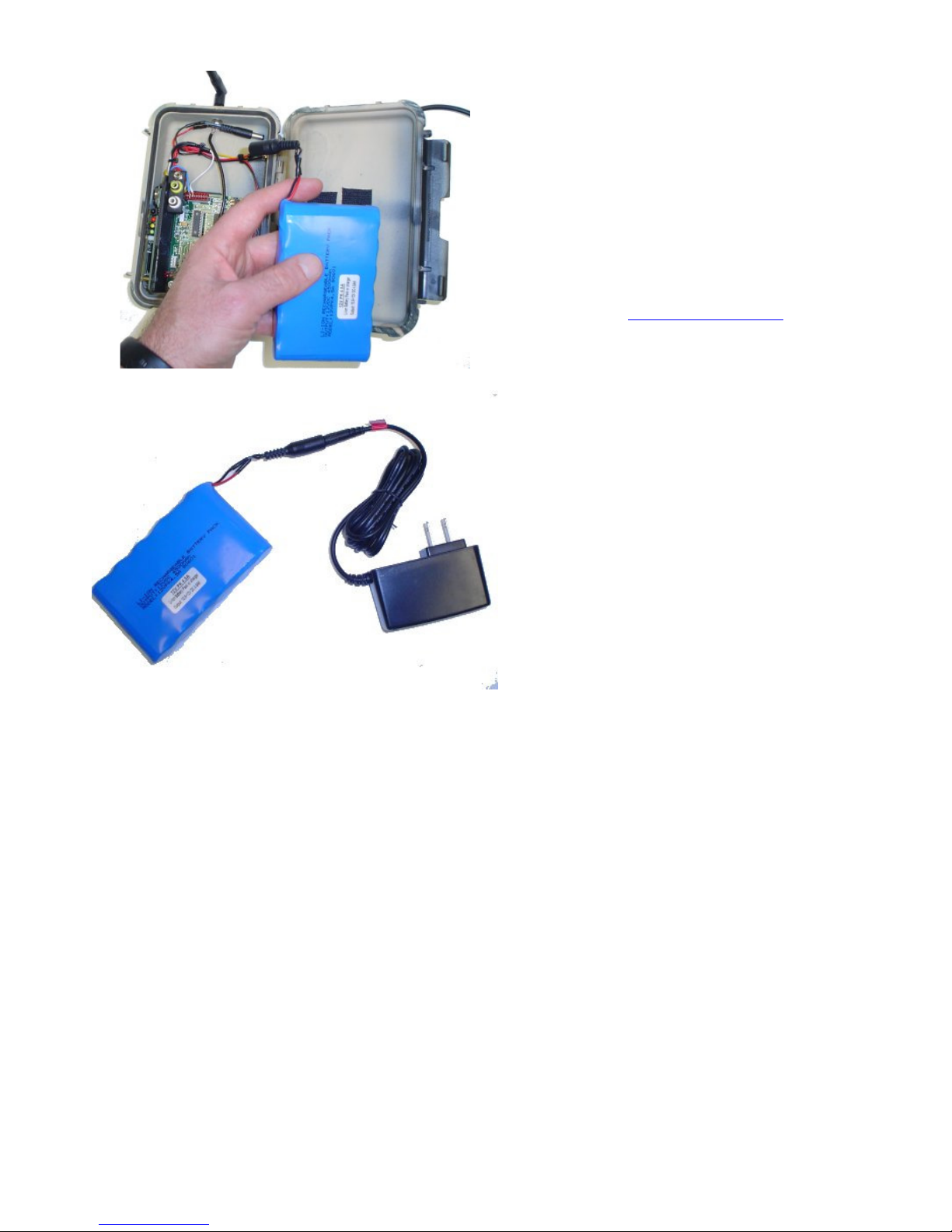
8. UndercoverEye™ Power Box 12V Battery & Charger
Included with your UndercoverEye unit is a
rechargeable 12V Li-Ion battery and 12V charger.
The 12V battery is completely removable from the
UndercoverEye unit for replacing or recharging.
To recharge the 12V battery simply connect the
barrel connector to the 12V wall charger unit.
When charging the red LED on the wall charger
will be lit and will change to green when the 12V
SLA battery is fully charged.
Replacement 12V Li-Ion batteries can be
purchased from www.pixcontroller.com.
15

9. Using your Power Box unit with different 12V devices
Figure 1: Connecting a Bullet Camera and Video
Transmitter
Using a Bullet Camera with Video Transmitter
The Power Box unit can also be used with various
cameras and video transmitters for a wireless connection
back to the UndercoverEye HDD or Trekker units. The
UndercoverEye HDD or Trekker units will need to have a
video receiving unit connected as shown below.
Note: When using a wireless video camera between
the Power Box and the recording unit such as the
UndercoverEye HDD or Trekker units both units need
to be in range of the wireless PIR motion sensor or
KeyFob. Both units need to power up at the same time
by this trigger device.
Figure 1 shows how to connect a bullet camera and video
transmitter to the Power Box. Connect one of the black
2.1mm power connectors to the bullet camera power input
and connect the other black 2.1mm power connector to
power input of the video transmitter. Next, connect the
video output from the bullet camera to the video input of
the video transmitter.
For a situation where you may need an IR array connect
the IR array to the silver 2.1mm power connector as
shown in figure 2.
You can purchase video cameras with built in IR arrays,
but these are typically larger cameras and do not lend
themselves well for covert setups.
Figures 3 and 4 show you how to connect the video
receiver to your UndercoverEye HDD or Trekker units.
Connect the 2.1mm power connector from the video cable
to the video receiver and the video input to the video
output of the video receiver.
Figure 2: Connecting a Bullet Camera and Video
Transmitter and IR Array
Figure 3: Connect the 2.1mm power connector from
the video cable to the video receiver and the video
input to the video output of the video receiver.
16
Note: When using a wireless video transmitter and
receiver be sure to check the video signal before
connecting the recording device. Video transmission
is limited by line of sight, obstructions such as
building, cars, or large metal objects, and topography.

Figure 4: Recording Setup - Video receiver
connected to the Trekker video input
Figure 5: Connecting an IR Array to the Power Box
for remote IR Illumination UndercoverEye HDD or
Trekker units.
Copyright ©, PixController, Inc. http://www.pixcontroller.com, all rights reserved.
PixController, Inc.
Connecting the Power Box to an IR Array
There are many situations where you may need some sort
of IR Illumination for your camera setups. Typically IR
Arrays are large and hard to conceal. Using the Power
Box for a remote IR Illumination will help with this
problem.
Simply setup the IR Array in a location elevated and out of
sight within range of your UndercoverEye HDD or Trekker
recording unit.
When a trigger event occurs both units will be triggered at
the same time. Be sure the day/night sensor is exposed
on the Power Box only to power the IR Array in dark
conditions.
Note: When using an IR Array with the Power Box and
the recording unit such as the UndercoverEye HDD or
Trekker units both units need to be in range of the
wireless PIR motion sensor or KeyFob. Both units
need to power up at the same time by this trigger
device
17
 Loading...