

Pivot SHUTTLE, Shuttle Race XT Build, Shuttle Team XTR Build, Shuttle Series Owner's Manual

PIVOT SHUTTLE
Owner's Manual
This manual is intended to provide you with the information
needed to get you on the trail. This guide will walk you through the
steps necessary to set up all the components and become familiar
with the Shimano STEPS E8000 System. This document contains
some helpful diagrams and reference material to make sure you
have everything necessary to maintain your Shuttle and enjoy it to
the fullest.
www.pivotcycles.com 1.877.857.4868
Performance. Redened.

Table of Contents
SECTION PAGE
1. Quick Start Guide 1
- Bike Set-up 1
- Charging the Battery 1
- Powering the System ON and OFF 1
- Assist Mode Operation
2. Basic Operation 2
- Assist and Shifter Switch Function 2
- Operating the Cycle Computer 2
- Screen Display 2
3. Bike Set-up 3
- Setting Proper Sag 3
- Setting Compression Damping on the Fox DPX2 3
- Setting Open Mode Adjust on the Fox DPX2 3
- Setting Rebound Damping on the Fox DPX2 4
- Setting Air Pressure on the Fox 36 Fork 4
- Setting Compression Damping on the Fox 36 Fork 5
- Setting Rebound Damping on the Fox 36 Fork 5
- Recommended Tire Pressure 5
- Adjusting Saddle Height 5
4. Shimano STEPS E8000 System 6
- Connecting to E-Tube Project 6
- Main Menu for E-Tube Project 6
- Customize Menu in E-Tube Project 7
- Update Firmware Menu in E-Tube Project 7
- Preset Menu in E-Tube Project 7
- Battery Charging Notes 8
- Charger LED Lamp 8
- Battery Power Panel LED Lamps 8
- Removing the Battery 9
- Installing the Battery 9
5. Troubleshooting 10
- Cycle Computer Warning Codes 10
- Cycle Computer Error Codes 10
- Battery LED Warning Codes 11
6. Schematics 12
- Shimano STEPS E8000 Schematic 12
- Small Parts Schematic 13
- Small Parts Table 14
- Wiring Diagram 15
7. Reference Material 16
- Shimano STEPS E8000 System 16
- Pivot Shuttle 16
1
www.pivotcycles.com 1.877.857.4868
Performance. Redened.

QUICK START GUIDE
1
This "Quick Start Guide" provides the essential information to set up your bike. For detailed information
about the Shimano STEPS E8000 System and bike set up, please refer to the full owner's manual.
Bike Set-up
• Before riding, reference the chart below as a rough guide on how to set the bike's components.
COMPONENT QUICK START SETTING
Body Weight in [kg] to [bar] 0.15 × Body Weight [kg] + 2.4 [bar]
Shock Air Pressure
(by Body Weight)
Fork Air Pressure 70 [psi] / 4.83 [bar]
Shock Compression Damping 7 clicks in (clockwise) from OPEN
Shock Rebound Damping 7 clicks in (clockwise) from OPEN
Fork Compression Damping 6 clicks in (clockwise) from OPEN
Fork Rebound Damping 8 clicks in (clockwise) from OPEN
Front Tire Pressure 18 [psi] / 1.24 [bar]
Rear Tire Pressure 22 [psi] / 1.52 [bar]
Adjusting Saddle Height
• The seat post collar on the Shuttle can be loosened and tightened with a 4mm hex wrench.
• Before raising or lowering the seat height, using a 2mm hex wrench, loosen the head tube cable port
securing the dropper post housing. Be sure to re-tighten the cable clamp after adjusting the saddle height.
Body Weight in [kg] to [psi] 2.2 × Body Weight [kg] + 35 [psi]
Body Weight in [lbs] to [bar] 0.07 × Body Weight [lbs] + 2.4 [bar]
Body Weight in [lbs] to [psi] Body Weight [lbs] + 35 [psi]
Charging the Battery
• The battery does not come charged and must be charged completely before the rst use.
• The charging port is located on the non-driveside of the downtube near the bottom of the battery.
• The battery has a sealing cover (g. 1) that needs to be removed for charging.
• The charging cable (g. 2) is plugged into the battery through the charging window in the frame. The
battery can also be charged o the bike. For battery removal instructions, see the full owner's manual.
• Make sure the the charger is securely attached. To verify that the bike is charging, the light on the charger
will illuminate and lights on the battery power panel will light up to indicate the charging level. For
additional information regarding the battery power indicator lights, see the full owner's manual.
Powering the System ON and OFF
• When powering the system ON or OFF, do not have your feet on the pedals; a system fault may result.
• The power button (g. 3) on the battery can be accessed through the window in the top of the downtube.
• Power cannot be turned on while the battery is charging.
• If the bike has not moved for 10 minutes, the power will shut o automatically.
1
2
3
Assist Mode Operation
• On start-up, the assist mode will be o. There are three levels of assistance: Eco, Trail, and Boost.
• The switch on the left side of the handle bar controls the level of assistance provided by the system.
www.pivotcycles.com 1.877.857.4868

BASIC OPERATION
2
Assist and Shifter Switch Function
• The operation procedure detailed below refers to the cycle computer default setting.
• Refer to the Shimano STEPS E8000 System Schematic for the switches part names.
(A)
(B) (C)
Y1 X1 Y2X2
BUTTON CYCLE COMPUTER (A) FUNCTION
Z1
BUTTON ASSIST SWITCH (B) FUNCTION
X1 Increase the level of assistance (Eco, Trail, and Boost)
Y1 Decrease the level of assistance (Press and hold for WALK mode)
BUTTON SHIFTING SWITCH (C) FUNCTION
X2 Up-shift rear derailleur (Pedaling becomes harder)
Y2 Down-shift rear derailleur (Pedaling becomes easier)
1) When Range displayed, the battery level is not displayed
2) Optional Item
3) When WALK assist is functioning Range displays [RANGE ---]
Switch display modes (Current Speed is default and will return after 60 seconds)
(Display Modes: Distance, Odometer, Range, Travel Time2, Avg. Speed2, Max. Speed2, Cadence2, Watts2, Calories2, Clock)
(Z1)
Operating the Cycle Computer
• The table below references the schematic above.
BUTTON CYCLE COMPUTER (A) FUNCTION
Z1
BUTTON ASSIST SWITCH (B) FUNCTION
X1 / Y1 Move menu cursor, adjusting settings, etc.
Switch between screens and conrm settings. (Press and hold to access menu screen)
(Menu Screens: Clear, Clock, Bluetooth, ANT, Light, Brightness, Sound, Units, Language, RD Adjust, RD Protection, Exit)
Screen Display
• The content below details the display layout for the cycle computer (A) in the Shimano STEPS E8000
System schematic.
(B)(A)
LETTER DISPLAY ITEM
A Battery level indicator
B Gear Position
C Assist Gauge
D Assist Mode Display
E Current Speed / Display Mode
1) Only displayed when using Di2
2) [ECO] mode automatically activates as remaining battery capacity declines
(E)
(C)(D)
www.pivotcycles.com 1.877.857.4868
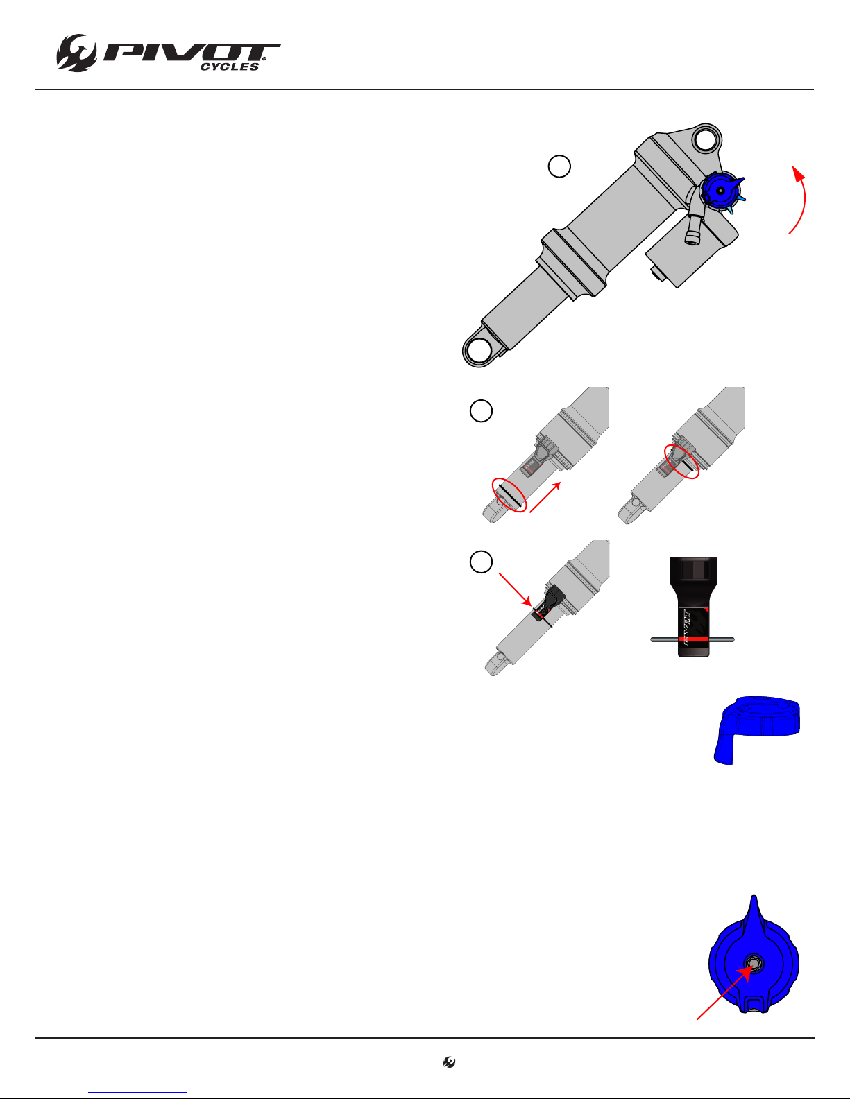
Setting Proper Sag
3
• Pivot uses dierent sag indicators depending upon
the bike model. The Pivot Shuttle uses Sag Indicator B.
1. Always set sag with the blue compression damping
adjust lever turned to the open position. (g. 1)
2. Have the rider stand on the pedals, preferably with
their hydration pack on, and have them sit down
hard into the saddle to achieve accurate sag settings.
The rider does not need to bounce up and down nor
should they sit down gently. If they sit down hard
once, the suspension will cycle well into the stroke
and return to the natural sag setting with the rider
in the saddle.
3. With the rider in the saddle and not moving, slide
the O-ring up into position against the air can. (g. 2)
4. Once the O-ring is set in place, have the rider slowly
step o the bike so as not to move the O-ring.
5. Make adjustments to the sag by removing or adding
air so that steps 2-4 result in the O-ring lining up
with the red line on the sag indicator (g. 3). It will
be necessary to cycle the shock after adding or
subtracting air before re-checking sag as the large
Evol negative air chamber will need to equalize
pressure with the main chamber each time air is
added or removed. You can do this by pushing down
on the saddle several times to compress the shock
past the sag point.
BIKE SET-UP
1
2
3
OPEN
MEDIUM
FIRM
Setting Compression Damping on the Fox DPX2
• The compression damping lever is a tuning tool to adjust compression support.
• All bikes can be run in the open position at all times and still perform well.
• Riders under 82 [kg] (180 [lbs]) will generally run the shock in the open position most of the
time.
• Riders over 82 [kg] (180 [lbs]) and aggressive riders may prefer the middle setting for more
mid-stroke support.
• The rmest setting is best suited for riding to the trail, long re road climbs, and smooth XC
courses.
Setting Open Mode Adjust on the Fox DPX2
• The Open Mode Adjust screw ne tunes the compression damping in the open position.
• The adjustment screw is a 3mm hex screw inside the top of the compression damping lever.
• This adjuster oers 10 additional ne tune adjustments for the open mode.
• Turning the screw clockwise will increase low speed compression damping; turning the
screw counter-clockwise will decrease low speed compression damping.
• Most riders will nd 7 clicks from full open is a good starting point.
www.pivotcycles.com 1.877.857.4868

Setting Rebound Damping on the Fox DPX2
4
• Rebound is set from the most open (fully counter-clockwise) position.
• The rebound setting is determined by the air pressure in the shock.
• Refer to the table below for the suggested rebound setting. The number in the chart
refers to how many clicks in (clockwise) from the open setting the rebound should be set.
BIKE SET-UP
AIR PRESSURE
[bar] [psi]
< 8.3 <120 Open
8.3 - 9.7 120-140 1
9.7 - 11 140-160 2
11 - 12.4 160-180 3
12.4 - 13.8 180-200 4
13.8 - 15.2 200-220 6
15.2 - 16.5 220-240 7
16.5 - 17.9 240-260 9
17.9 - 19.3 260-280 11
19.3 - 20.7 280-300 12
SUGGESTED REBOUND
SETTING
Setting Air Pressure on the Fox 36 Fork
• Fox recommends setting sag between 15% and 20% of the total fork travel. The Shuttle comes with a
150mm fork, so the proper sag measurement is 22.5 - 30.0mm.
• The air pressure in the Fox 36 fork should not exceed 8.3 [bar] (120 [psi]).
• To achieve the proper sag, reference the chart below for an initail starting point.
95 - 100 210 - 220 5.4 [bar] / 79 [psi]
100 - 105 220 - 230 5.7 [bar] / 83 [psi]
105 - 109 230 - 240 6.0 [bar] / 87 [psi]
109 - 114 240 - 250 6.3 [bar] / 91 [psi]
www.pivotcycles.com 1.877.857.4868
RIDER WEIGHT
[kg] [lbs]
55 - 59 120 - 130 3.0 [bar] / 43 [psi]
59 - 64 130 - 140 3.2 [bar] / 46 [psi]
64 - 68 140 - 150 3.5 [bar] / 51 [psi]
68 - 73 150 - 160 3.8 [bar] / 55 [psi]
73 - 77 160 - 170 4.1 [bar] / 59 [psi]
77 - 82 170 - 180 4.3 [bar] / 63 [psi]
82 - 86 180 - 190 4.6 [bar] / 67 [psi]
86 - 91 190 - 200 4.9 [bar] / 71 [psi]
91 - 95 200 - 210 5.2 [bar] / 75 [psi]
FOX 36
AIR PRESSURE

BIKE SET-UP
5
Setting Compression Damping on the Fox 36 Fork
• To set compression, start from the open (or fastest) position by turning the black compression dial on the
top of the right fork leg counterclockwise until it stops clicking.
• Turn black dial clockwise in 2-8 clicks in (depending on rider weight). Most riders should feel comfortable
with 6 clicks in as a starting point.
• Lighter riders will generally prefer less compression damping (fewer clicks from open).
Setting Rebound Damping on the Fox 36 Fork
• To set rebound, start from the open (or fastest) position by turning the red rebound dial on the bottom of
the right fork leg counterclockwise until it stops clicking.
• Turn red dial clockwise in 5-8 clicks in (depending on rider weight). Most riders should feel comfortable
with 8 clicks in as a starting point.
Recommended Tire Pressure
• Tire pressure is an important factor on having the bike ride properly. If the tire pressure is too high, the tire
will not conform to ground, reducing traction. If the tire pressure is too low, the tire could pinch at.
• It is important to have an accurate pressure gauge when setting tire pressure; preferably a digital gauge
with a 0.03 [bar] (0.5 [psi]) accuracy.
• The recommended tire pressure will vary slightly based on rider weight, riding style, and terrain.
• Some riders may nd it helpful to start a ride at a slightly higher pressure than recommended and let out
a little air throughout the course of the ride until you nd your ideal riding tire pressure.
RECOMMENDED TIRE PRESSURE
FRONT REAR
1.24 [bar] / 18 [psi] 1.52 [bar] / 22 [psi]
Adjusting Saddle Height
• The seat post collar on the Shuttle can be loosened and tightened with a 4mm hex wrench.
• Before raising or lowering the seat height, using a 2mm hex wrench, loosen the head tube cable port
securing the dropper post housing.
• The dropper post cable should be routed through the cable port on the driveside of the head tube. This
cable port cap is used to hold the dropper post cable and cycle computer wire in place.
• Be sure to re-tighten the cable clamp on the head tube cable port after adjusting the saddle height.
4mm
Hex Wrench
2mm
Hex Wrench
www.pivotcycles.com 1.877.857.4868

SHIMANO STEPS E8000 SYSTEM
6
Connecting to E-Tube Project
• The display layout and switch operation can be customized through the Shimano E-Tube Project.
• The Shimano E-Tube project can be accessed via the Shimano E-Tube Project app available in the App
Store or through the software, which can be downloaded from Shimano's website.
• The E-Tube Project app is compatible with both Android and Apple devices. At the time of publication, the
E-Tube Project software is only available for Windows operating systems. Check Shimano's website for the
latest information regarding the E-Tube Project software.
• Links to Shimano's website to download the software are in the "Reference Material" Section of this manual.
Connecting via the E-Tube Project app:
1. Before setting up a connection, turn on the Bluetooth connectivity of the smart phone or tablet.
2. Open the E-Tube Project app and set it to receive for Bluetooth signals.
3. Press X1 or Y1 button on the Assist Switch (B) to select [Start] on the cycle computer (A). Refer to the
diagram on Page 2.
4. To start the Bluetooth connection, press the Z1 button on the cycle computer (A). If you press the Z1
button again, during the connection process, the transmission will be interrupted and the screen will
return to the menu list.
5. When the connection is successful, the Shimano STEPS logo will be displayed. If the connection is not
successful a "Connect failure" message will appear. The rst time you connect the password is "000000".
6. When the connection is successful, the unit name will be displayed in the E-Tube Project app. Select
the unit name in the app to customize the unit.
7. To disconnect, cancel the Bluetooth connection from the smart phone or tablet. The cycle computer
(A) will exit the connection mode and return to the regular operation mode.
Connecting via a computer with the E-Tube Project software:
1. Connect a USB cable from the computer to the Communication Box (SM-PCE1). The Communication
Box is not included with Shuttle and must be purchased separately.
2. Connect the Communication Box to the open port in the cycle computer.
3. Open the E-Tube Project Software and select E8000 from the Shimano STEPS menu.
4. On the next screen select "Connection Check".
5. On the following screen conrm by selecting "Next".
6. The next screen will list the devices recognized by software. There should be 5 devices listed: The drive
unit, the cycle computer, the rear derailleur, the assist switch, and the shift switch.
7. Select "Complete" to nish the operation and complete the connection to the system.
Main Menu for E-Tube Project
• The main menu to the E-Tube Project has three main components that are relevant for the consumer to
know how to navigate and operate: Customize, Update Firmware, & Preset.
• In the E-Tube Project software, after clicking "Complete" a list of buttons will appear corresponding to the
menu options.
• When using the E-Tube Project app, after making the connection, a group of icons will appear that
correspond to the menu items. The table below will show what the icons look like.
ICONS IN E-TUBE PROJECT APP
CUSTOMIZE UPDATE FIRMWARE PRESET
www.pivotcycles.com 1.877.857.4868

SHIMANO STEPS E8000 SYSTEM
7
Customize Menu in E-Tube Project
• The Customize menu is sub-divided into menus for individual units: Drive Unit, Display Unit, Switch Setting,
and Multi Shift Setting
• The tables below show the available options within the Customize menu.
DRIVE UNIT SETTING DESCRIPTION
Light Sets whether to use a light.
DISPLAY UNIT SETTING DESCRIPTION
Display Units Switches the measurement units between km and mile.
Display Switchover Sets whether to display traveling time, average speed, maximum speed, cadence, and current time.
Time Setting Sets the correct current time.
Beep Setting Switches the beep sound on or o.
Brightness Adjusts the backlight's brightness.
Dislay Language Sets the language used between English, French, German, Dutch, Spanish, and Italian.
SWITCH SETTING DESCRIPTION
Shifting Switch Sets the shift direction of buttons X2 and Y2 on the Shifting Switch (C)
MULTI SHIFT SETTING DESCRIPTION
Multi Shift Switches the multi shift function on or o.
Gear-shifting Interval Adjusts the shifting speed of multi shift mode. Does not aect shifting speed of individual shifts.
Gear Number Limit Sets how many gears the derailleur will shift through in multi shift mode.
Update Firmware Menu in E-Tube Project
• There is a button in the main menu to update the rmware.
• By pressing the "Update Firmware" button, the software automatically searches for and downloads any
update for the system.
• Once the program has completed any updates, each component of the Shimano STEPS E8000 System will
be listed with the corresponding version of the latest rmware for that component.
Preset Menu in E-Tube Project
• The E-Tube Project allows saving and loading custom settings les.
• Any customized setting can be saved as a preset settings le.
• Settings les can also be pulled from a bike and saved as a preset settings le. The saved settings can be
uploaded to other bikes to duplicate the settings on other bikes.
• To create a preset settings le on the app:
1. Make any changes to the settings of the bike in the Customize menu.
2. Upload the changes to the bike.
3. Open the Preset menu and click on, "Loading settings from the bike".
4. Click on the "Connected" button on the bottom of the screen.
5. The settings that were just uploaded will now appear listed on the screen. By scrolling to the bottom
of the screen, the le name can be edited.
6. Click on the download button on the bottom of the screen. A conrmation of the successful download
will appear.
7. Now, the saved a preset settings le will appear under the "Load a settings le" option within the
Preset menu.
www.pivotcycles.com 1.877.857.4868

SHIMANO STEPS E8000 SYSTEM
8
Battery Charging Notes
• The battery does not come charged and must be charged completely before the rst use.
• Only charge the battery with a desginated charger, such as the one included with the bike.
• Battery can be used once the LEDs on the power panel light up.
• When removing the charger from the outlet or the port, pull on the plug, not the cord.
• When charging the battery, plug the cord into the wall outlet rst, and then into the battery.
• Be sure the the charger is on a at and stable surface, when charging.
• Do not leave the battery fully depleted for an extended period of time. This will cause the battery to
deteriorate and reduce the battery capacity.
Charger LED Lamp
• After charging has started, the LED lamp on the charger lights up.
Charger LED Lamp
LED INDICATOR DESCRIPTION
Lit Up
Blinking
Turned o
Battery Charging (or within 1 hour after the completion of charging)
Charging Error
Battery Disconnected (or 1 hour or more after the completion of charging)
Battery Power Panel LED Lamps
• You can check the charge level of the battery during charging and while riding.
BATTERY LEVEL WHILE CHARGING* BATTERY LEVEL WHILE RIDING*
0% - 20% 0%, Power OFF / Shutdown
21% - 40% 20% - 1%
41% - 60% 40% - 21%
61% - 80% 60% - 41%
81% - 99% 80% - 61%
100% 100% - 81%
www.pivotcycles.com 1.877.857.4868
*
: No Light : Lit Up : Blinking

SHIMANO STEPS E8000 SYSTEM
9
Removing the Battery
• The battery may need to be removed to swap batteries or charge the battery if there is no power supply
near the bike.
• When the battery is removed, the cover will stay attached to the bike, and the front battery bracket will
stay attached to the battery.
2
4
1. Using a 3mm hex wrench, remove the eight M6
bolts securing the battery cover to the frame.
Support the cover as while removing the last
bolts, since the battery is attached to the cover.
2. Pull the rear of the cover downward until the wire
harness clears the frame. Once the wire clears
the frame, pull the cover backwards to pull that
battery out of the frame.
3. Using a 4mm hex wrench, remove the two M5
bolts securing the battery to the battery cover.
4. Pull the battery upward to remove the battery
from the cover.
1
3mm
Hex Wrench
3
4mm
Hex Wrench
Installing the Battery
• To install the battery, reverse the removal procedure from above.
1
1. Install the battery onto the cover by aligning the
rear of the battery with the battery receiver and
then lowering the front of the battery into place.
2. Push the battery backward to ensure tight
engagement between the battery and receiver.
3. Thread the M5 bolts into the battery bracket
through the slots on the battery cover. Make sure
the washers are between the bolt head and the
battery cover. Tighten the bolts to 7 Nm.
4. Insert the front of the battery into the battery
cavity and slide it forward until the rear of the
battery clears the back edge of the cavity. Lift the
back edge of the battery into the battery cavity.
Make sure that the battery cable clears the back
edge of the battery cavity when installing the
battery.
5. Apply blue Loctite 243 on the threads of the
eight M6 battery cover bolts.
6. Using a 3mm allen wrench, replace all eight M6
bolts and tighten to 5 Nm.
3
Hex Wrench
5
4mm
(7 Nm)
Apply
Loctite 243
2
4
6
3mm
Hex Wrench
(5 Nm)
www.pivotcycles.com 1.877.857.4868

Cycle Computer Warning Codes
10
• Warnings may appear on the cycle computer display if the system
detects an issue.
• The warning code will clear once the issue is resolved.
• If any issues persist after the suggestions below, contact the place
of purchase.
TROUBLESHOOTING
CODE ISSUE
W010
W011
W013
W032
Drive unit operation temperature is higher than normal
Traveling speed cannot be
detected
Torque sensor was not initialized
properly
Electronic derailleur installed in
place of a mechanical derailleur
Power assistance may be lower
than usual
Maximum speed may be lower
than usual
Power assistance may be lower
than usual
Power assistance provided in
[WALK] may be lower than usual
OPERATIONAL
RESTRICTION
Cycle Computer Error Codes
• An error message may appear on the cycle computer if the system
detects an issue.
• If any issues persist after the suggestions below, contact the place
of purchase.
CODE ISSUE
E010
A system error was detected Power assistance is not
OPERATIONAL
RESTRICTION
provided during riding
REMEDY
Stop using the assist function until the
drive unit temperature drops.
Check that the speed sensor is installed
correctly.
Change the assist switch to the gear shifting switch and turn the power on again.
Reinstall the derailleur for which the system is congured to support.
REMEDY
Press the power button of the battery to
turn it on again.
E011
E013
E014
E020
E021
E022
E043
An error occured in system opreation Power assistance is not
An anomaly was detected in the drive
unit's rmware
The speed sensor may be installed in the
wrong position
A communication error between the battery and drive unit was detected
Battery connected to the drive unit is not
supported
The battery connected does not conform
with system standards
Part of the cycle computer's rmware
may be damaged
www.pivotcycles.com 1.877.857.4868
provided during riding
Power assistance is not
provided during riding
Power assistance is not
provided during riding
Power assistance is not
provided during riding
Power assistance is not
provided during riding
All system functions
shutdown
Power assistance is not
provided during riding
Press the power button of the battery to
turn it on again.
Contact the place of purchase.
Contact the place of purchase.
Check that the cable between the drive
unit and battery is properly connected.
Press the power button of the battery to
turn it on again.
Press the power button of the battery to
turn it on again.
Contact the place of purchase.

TROUBLESHOOTING
11
Battery LED Warning Codes
• System errors and warnings can be indicated by various lighting patterns on the battery's power panel.
• If any issues persist after the suggestions below, contact the place of purchase.
ERROR TYPE ISSUE LIGHTING PATTERN* REMEDY
SYSTEM
ERROR
Communication error with
the bicycle system
Make sure the battery cable is not
loose or improperly connected.
TEMPERATURE
PROTECTION
SECURITY
AUTHENTICATION
ERROR
CHARGING
ERROR
BATTERY
MALFUNCTION
If the temperature exceeds
the guaranteed operating
range, the battery output is
shut o
This is diplayed if a genuine
drive unit is not connected
or if any of the cables are
disconnected
This is displayed if there is an
error during charging
Electrical failure inside the
battery
Leave the battery in a cool place
away from direct sunlight until the
internal temperature of the battery
decreses suciently.
Connect a genuine battery and
drive unit. Check the condition of
the cables.
Remove the charger from the battery and press the power button. If
an error appears, contact the place
of purchase.
Connect the charger to the battery and then remove the charger.
Press the power button with only
the battery connected.
*
: No Light : Lit Up : Blinking
www.pivotcycles.com 1.877.857.4868
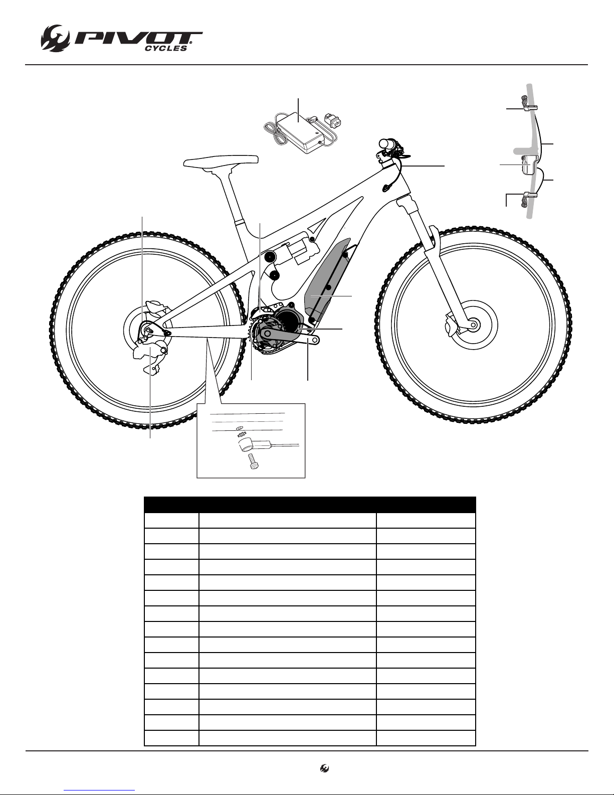
Shimano STEPS E8000 System Schematic
12
(J)
SCHEMATICS
(B)
(M)
(O)
(K)
(L)
(A)
(N)
(E)
(C)
(I)
(G)
(D)
(H)
(F)
LETTER PART DESCRIPTION PART NAME
A Cycle Computer SC-E8000
B Assist Switch SW-E8000-L
C Shifting Switch SW-M8050-R
D Front Chainring SM-CRE80-B
E Chain Device SM-CDE80
F Crank Arm FC-E8050
G Drive Unit DU-E8000
H Speed Sensor SM-DUE10
I Battery / Mount BT-E8010 / BM-E8010
J Battery Charger EC-E6000
K Rear Derailleur (Di2) RD-M8050
L Cycle Computer E-Tube Wire (1000mm) EW-SD50
M Assist Switch E-Tube Wire (400mm) EW-SD50
N Shifting Switch E-Tube Wire (300mm) EW-SD50
O Rear Derailleur E-Tube Wire (900mm) EW-SD50
www.pivotcycles.com 1.877.857.4868
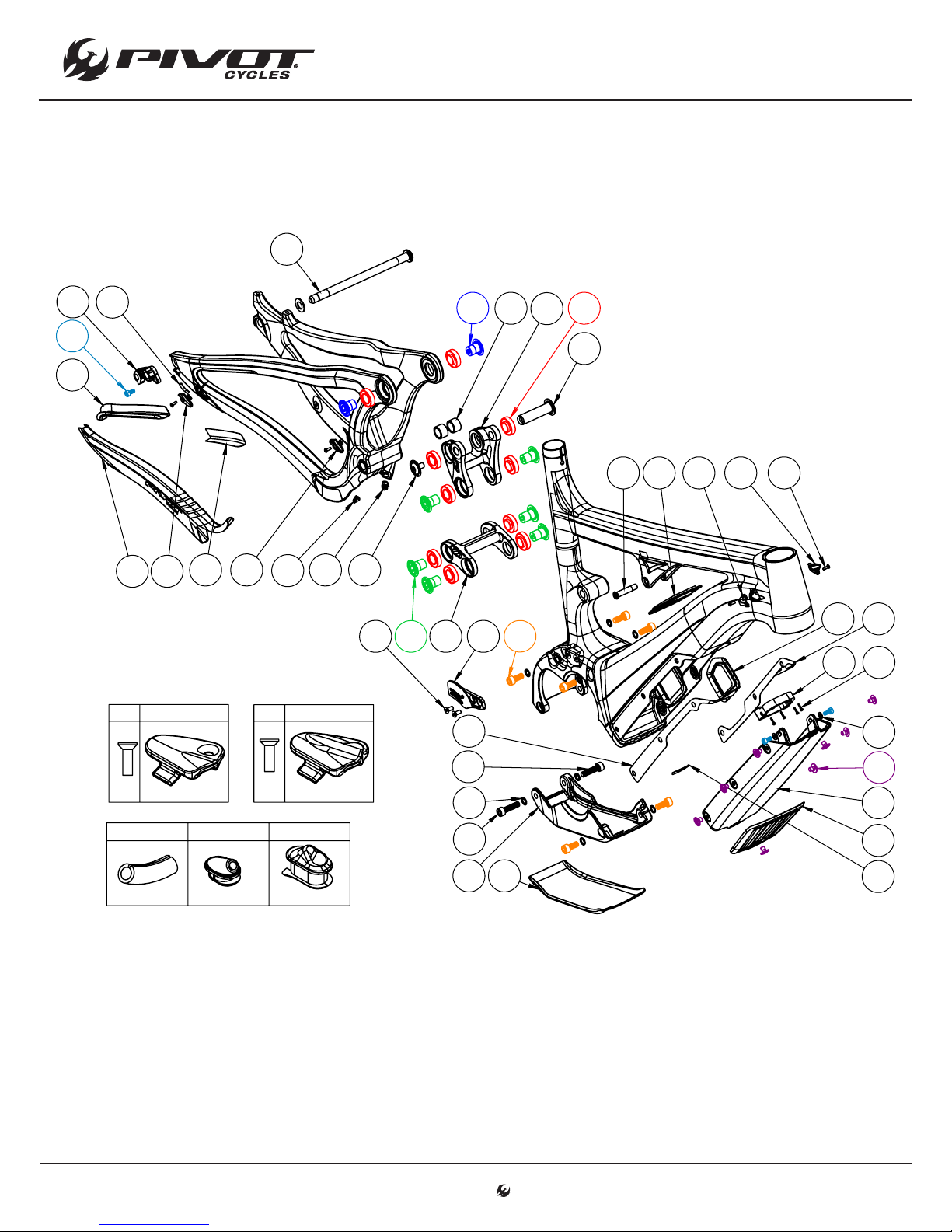
Small Parts Schematic
13
15
28
99
SCHEMATICS
24 1925
21
16
42
41 27
30 27
45
29
31
30 29
32 23
26
20
12
39
22
18 302729
35
13
36
383334
10811
17
37
x1
28 31 32
x1
www.pivotcycles.com 1.877.857.4868
39
94043
44
14

SCHEMATICS
14
Small Parts Table
NUMBER PART NAME DESCRIPTION TORQUE *
8 FP-CVR-EBIKE-BATT Battery Cover
9 FP-CVR-EBIKE-SKD-PLT Skid Plate
10 FP-MNT-FRNT-BATT-V1 Front Battery Mount
11 FP-SCW-BTN-M2.5*12-SLFTAP M2.5x12 Self-tapping Torx Screws
12 FP-GKT-BATT-CVR-DS-V1 E-Bike Carbon DS Battery Cover Gasket
13 FP-GKT-BATT-CVR-NDS-V1 E-Bike Carbon NDS Battery Cover Gasket
14 FP-GKT-BATT-CVR-BLT-V1 E-Bike Carbon Rear Bolt Battery Cover Gasket
15 FP-RDH-TA-12MM-BLK-V2 Direct Mount Rear Derailleur Hanger 12mm TA
16 FP-SCW-SCK-M5*10
17 FP-WSH-5I*10O*1W M5 Battery Mount Washers
18 FP-BLT-M8*38-BLK M8x38 Front Shock Bolt 13 Nm (10 lb·)
19 FP-BRG-6902-LLUMAXECN 28mm 6902 Ext'd Max-E Bearing
20 FP-LNK-LL-50MM-V1 50mm Out-to-Out Lower Link
21 FP-LNK-UL-70MM-DSM-V1 70mm Direct Shock Mount Upper Link
22 FP-PIN-SHK-M8*15O-BLK 15x58mm M8 Rear Shock Pin 13 Nm (10 lb·)
23 FP-BLT-M8*12-BLK M8x12 Rear Shock Bolt 13 Nm (10 lb·)
24 FP-WSH-SPC-M15*13 M15x13 Rear Shock Spacer
25 FP-BLT-M14*17-BLK M14x17 Upper Link Bolt 35 Nm (27 lb·)
26 FP-BLT-M14*20-BLK-V2 M14x20 Lower Link Bolt 35 Nm (27 lb·)
27 FP-CLM-MECH-FRM-V1 Internal Routing Cable Clamp
28 FP-CLM-DI2-SLV-BLK-V1 Di2 Wire Sleeve for Cable Clamps
29 FP-CLM-DUAL-FRM-V1 Internal Routing Dual Clamp
30 FP-SCW-FLT-M3*10 M3x10 Cable Clamp Screw (Included w/ Clamp)
31 FP-GDE-DI2-7*8*2.5*2.5 7x8mm Di2 Wire Guide
32 FP-GDE-DUAL-7*13*5-V1 Extended Dual Wire/Housing Guide
33 FP-MNT-CG-V1 Chain Guide Mounting Plate
34 FP-SCW-FLT-M5*12 M5x12 CG Mounting Screw
35 FP-GKT-BATT-IND-V1 Battery Indicator Gasket
36 FP-GKT-BATT-CHG-V1 Battery Charging Port Gasket
37 FP-BLT-M6*8-BLK-V1 M6x8 Battery Cover Bolts 5 Nm (4 lb·)
38 FP-SCW-SCK-M8*18-R1 M8x18 Motor Mounting Screw 13 Nm (10 lb·)
39 FP-SCW-SCK-M8*30-R1 M8x30 Motor Mounting Screw 13 Nm (10 lb·)
40 FP-WSH-8I*12O*1W M8 Motor Mount Bolt Washer
41 EBIKE CS GUARD E-Bike Carbon Chainstay Protector
42 EBIKE SS GUARD E-Bike Carbon Seatstay Protector
43 EBIKE SP GUARD E-Bike Carbon Skid Plate Protector
44 EBIKE BC GUARD E-Bike Carbon Battery Cover Protector
45 EBIKE SS EXT GUARD E-Bike Extended Seatstay Protector
99 157MM THROUGH AXLE V3 157mm Thru Axle w/ Washer
= grease = anti-seize = anti-seize or grease = loctite 243 (applied to female threads)
*
M5x10 Rear Derailleur Hanger Socket Screw 7 Nm (5 lb·ft)
M5x10 Battery Bracket Socket Screw 7 Nm (5 lb·ft)
www.pivotcycles.com 1.877.857.4868

SCHEMATICS
15
Shuttle Wiring Diagram
• The diagrams below will help illustrate how the wires are to be routed through the internal cable guides
and how the handlebar switches are attached to the cycle computer.
• The routing shown below will help minimize the likelihood of pinching a wire when removing and installing
the motor for maintenance purposes.
-----------------
-----------------
----------------
-----------------
-----------------
-----------------
Cycle Computer Wire / EW-SD50 (1000mm)
Assist Switch Wire / EW-SD50 (400mm)
Shifter Wire / EW-SD50 (300mm)
Rear Derailleur Wire / EW-SD50 (900mm)
Speed Sensor Wire / SM-DUE10
Battery Cable / BM-E8010
www.pivotcycles.com 1.877.857.4868
Frame Wiring Diagram
Cycle Computer Wiring Diagram

REFERENCE MATERIAL
16
Shimano STEPS E8000 System
• Additional information regarding operation and functionality of the Shimano STEPS E8000 System can be
found at: http://si.shimano.com/#/
• To download the E-tubes Project software to fully utilize the connectivity of the Shimano STEPS E8000
System visit: http://e-tubeproject.shimano.com/
Pivot Shuttle
• For FAQs and additional technical documents regarding the maintenance of the Pivot Shuttle can be found
at: http://www.pivotcycles.com/bike/shuttle/
www.pivotcycles.com 1.877.857.4868
 Loading...