

Page 1
REV COUNTER RCX
(RCX As of Octo ber, 2013 No.1)
USER’S MANUAL
REV COUNTER
SHIFT LAMP & REV COUNTER for Pros
Thank you for purchasing this PIVOT product.
Please read this manual carefully and keep it for future
reference.
●If this product is given to
another u ser, make sure to
include this User’s Manual.
Product
+
Contents Please check the contents of the package
Contents / WARNING / CAUTION ……… 1 Features …………………………………… 1 Connecting The Wires …………………… 2 Installing The Product …………………… 3 Settings……………………………………… 3 Basic Operation …………………………… 4 Display The Peak Value and Reset …… 4 Troubleshooting …………………………… 4
WARNING
●Do not work in areas where there is excessive exhaust.
Due to vehi cle exhau st emission poi soning or fire may re sult in a damage to
humans.
●Please securely fasten the product to a stable place.
It is very d angero us if, whil e in use, the p roduc t falls of f and interferes w ith brak ing.
●Do not crush the cable.
Please be careful t hat the ca ble doe s not get cr ushed by t he seat rail or car do or
steel pl ate, nor cut by any sharp s teel plate as this may cause a po or connection or
an elec tric sho rt lead ing to fire or other danger.
●Do not op erate while driving.
Operat ing or checking the disp lay during drivi ng may caus e an acci dent; please use
with the u tmost c onsideration for safety.
●Please be sure to store bundle away all wires with tape, etc...
It is very danger ous to pull tangle d wires by force or all ow tangl ed wires to interfe re
with driving.
Improp er use or di sregar d of these w arning s may
result i n the injury or death of peop le.
OBD2
Shift Lamp
Cut Connectors
× 4
Controller
Double-sided
Tape
CAUTION
●This product is for DC12V cars;
Installation cannot be carried out on cars with other voltage batteries.
●Just after installation do not exert any strong force on the product.
When double- sided t ape is used for an ins tallation be warned that wh en hot the
tape temporarily losses adhesiveness.
●Do Not Use Chemical Cleansers.
If the uni t gets dir ty please wipe with a sof t cloth to remove any dirt. Do n ot use
chemical cleansers such as thinner, benzene, or alcohol.
●Do not install the product in any place subject to high temperature
or any place where water may be splashed.
●Make sure to replace all screws and parts to their original place.
●Do not install the product in a place where it will cause distraction.
●Do not, in any manner, process, take apart, or make changes to
this product.
Power Cable
with fuse 3A
Allen
Wrench
Improp er use or di sregar d of these warning s may
cause in jury to p ersons , damage t he product and
other things.
extension
Zip Ties
× 5
White
cord
Earth
terminal
User’s guide
ECU wiring
diagram list
Features
Shift Lamp
■
Shift lamp lights up when the set rpm is reached.
Ultra bright LED is easy to see even in full daylight.
・
For night driving select auto low light ing or synchronize w ith parking lights.
・
High quality aluminum machined body with swivel neck.
・
Digital Tachometer
■
High precision display for setting shift lamp and viewing rpm.
High precision display of engine rpm up to 9999 in 1 rpm units.
・
Shift lamp settings can be made in units of 100 rpm.
・
View real time and peak engine rpm.
・
Compac t design needs no space.
・
Alarm
■
Alarm sounds at shift point for 0.5 seconds.
Easy Installation
■
Can be easily installed in some model TOYOTA and DAIHATSU cars
directly by connecting to the diagnostics connector. Other models can be
connected to the ECU.
Compatible Vehicles
■
12 V Gasoline Engine Cars (some diesel engine models)
For 1・2・3・4・5・6・8 cylinder models.
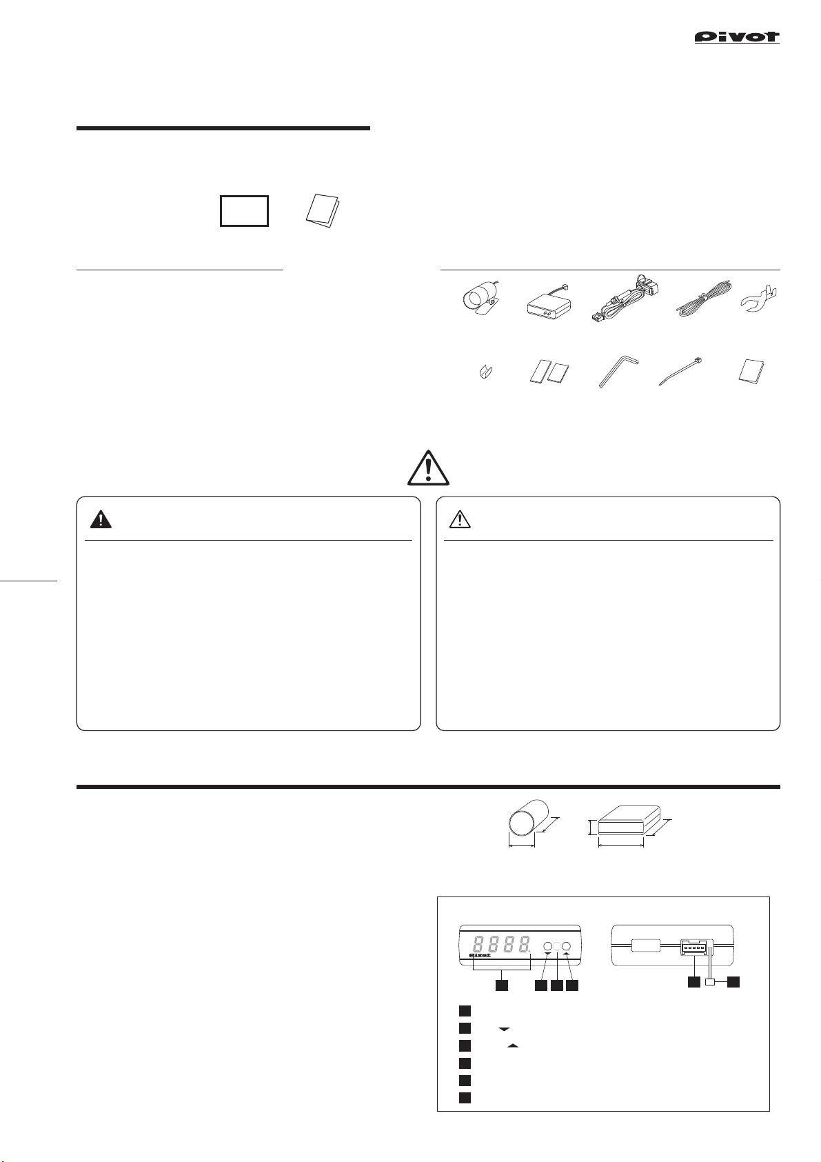
Size
■
[Unit:mm]
(Shift Lamp) (Controller)
46
32
20
Part Names of the Controller
(Front) (Backside)
REV COUNTER
12634
Display
1
SET( ) switch
2
PEAK( ) switch
3
Light sensor
4
5-pin Connector
5
2-pin Connector
6
SET
PEAK
rpm
RPM and eac h setting disp lay
Change each setting
Peak and change each sett ing
For Automatical ly low lighting
Connect to the 5 -pin Co nnecto r of Power cab le
Connect to the 2-p in Connector of Sh ift Lamp
60
50
5
1
Page 2

Connecting the Wires
Red
Red
Black
Black
White
White
Red
Black
White
1
Type
Backside of the controller
Type
Connect to the Power and RPM signal
Car models with a ● or ◎ mark in the
“ECU Wiring Diagram List”
:
A
(Some of TOYOTA, DAIHATSU and MINI)
Connect to the diagnostic
monitor connector
OBD2
5-pin
connector
: If you are not using the diagnostic monitor connector
C
Connector
Backside of the controller
Type
:For Popular Models (other than TOYOTA, DAIHATSU and MINI)
B
5-pin
connector
If you are wiring directly cut off and insulate all wires at the base of the OBD2 connector.
12
←To controller
Cut off at the base
RedRed
BlackBlack
WhiteWhite
OBD2
connector
■ Explanation of wires
Color
Red
Black
White
Orange
Wiring place
IGN
GND
TA
Illumi
Details
12V with key switch ON (or Normal power)
Screw to ga in eart h, etc
RPM signal
12V with park ing light s ON
Backside of the controller
5-pin
connector
●
⇒
●Automatically low lighting
⇒ No need to make wiring
IGN (or Normal power)
BlackBlack
WhiteWhite
Orange wire
Synchronize wit h parkin g lights
Need to make wiring
RedRed
※1
Connect to the diagnostic
monitor connector
Engine Computer,
Earth
= Use cut connector (or solder)
OBD2
Connector
Cut off
WhiteWhite
at the base
Insulate the cut
off part with tape
RedRed
BlackBlack
White ※1
If the white wire is not long
※1
enough, please use the
white wire provided in this package to extend the length.
ECU
etc.
See 【Reference 2】
Cut connector
TA
Backside of the controller
5-pin
connector
Cut the black tube of the wire tip and connect.
Orange
ECU
Engine Computer,
etc.
TA
White
extension wire
Insulate the cut off
part with tape
Parking
light
When another device is already
connected to the RPM signal
from the ECU
●To get the RPM signal from diagnosis
To get the RPM
signal from other
than the ECU
2
Connect to the Shift Lamp
(check connector)
Ex : in ca se of
MAZDA EUNOS
ROADSTER
(NA6C)
←To controller
... and that device works properly keep that wiring.
... and the meter or other device stops working properly or sometimes becomes unstable disconnect from
the ECU wire and get the RPM from the minus terminal of ignition coil or diagnosis. (Follow the directions
as written below)
Location of the
RPM sign al (IG − )
White wire
Insert the 2-pin connector from the shift lamp into the 2-pin connector at the back
of the controller.
Backside of the controller
Shift Lamp
2-pin connector
【Reference 1】Notes about using the OBD 2 Connector
Make sure to g rip the
distended portions when
pullin g it out or inserti ng it.
CAUTION
Do not pul l on the wires
when tr ying to remove the
conne ctor; th e wires may
become disconnected.
If you unable to get a gripon the distended portions.
With some car mod els
it may be difficu lt to
get a goo d grip on the
connector.
●To get the RPM signal from
the igni tion coil
White wire
←To controller
Ignition coil
ー
About Using OBD2 Products in Combination
If you wish to use REV COUNTER in combination with products in
our 3- drive S eries (FLAT or COMPACT) or other OBD 2 products, th e
“OBD2 W iring Kit OBD- EH” (sold separately ¥ 3,2 00) mak es
installation a snap.
For more d etail s about using combinations of pro ducts s ee here.
⇒
http://pivotjp.com/o bd- e/
When usi ng REV COU NTER with p roduc ts menti oned above, they can
*
only be us ed toget her in com patibl e model ve hicles for both products.
When co nnect ing the RPM signal to the
igniti on coil or d iagnos is and th e indica ted
rpm on the meter may be obvio usly lowe r
than th e actual rpm as show n on tach omete r
Ex : For a 6 cyli nder car, th e reading s hould be 3 000
rpm, but d isplay sh ows 500 rp m.
This may be c aused by th e indivi dual wir ing system
of that mod el of car. Chan ge the cyl inder set ting to
“1”. (See page 3 “SE TTING S A” for detail s.)
In such c ase, pull
out the connector by
pullin g on the end of
the zip ti e.
【Reference 2】How to use the Cut Connectors
10 mm
1
Peel off of t he vinyl
cover at connection.
When cri mping, p lease us e crimper s or use pli ers to ben d and then s older tog ether.
*
10 mm
2
Peel off of t he vinyl
cover at the e nd of
the prod uct’ s wire.
3
Wrap around both
wire coils.
2
4
Close ti ghtly wi th
cut connector.
5
Insulate with
vinyl tape.
【Reference 3】How to use provided e arth terminal
1.
Peel off a bout 10mm of vi nyl coveri ng from the t ip of
the blac k wire.
2.
Bend the outside wires around the core to
make the wir e thicker.
3.
Crimp down on the earth terminal.
4.
Connec t it to a ear th screw.
Crimp down
Page 3

Fastening the products
On the steering
column cover
Below the
meter hood
On the steering
column cover
On the da shboard
Installation of the Shift Lamp
(Installation Method)
On the da shboard
On the steering
column cover
Adjust to
designed
angle
Double-sided
tape (included)
Clean to remove
oil or dus t
Hexagonal bolt
Fasten using the
①
double-sid ed tape.
(Clean the surfac e;
removing all oil or dust.)
After decidin g the
②
position and angle of
the meter face, fasten
the hexag onal bolts on
both sid es to sec ure.
Settings
SETTING
A
Set the cylinder number for the car being used.
1
2
Patterns for cylinder set tings display
1-cylinder 234568Special A
Cylinder Number Setting
ON
Press the S ET switc h for 5 seco nds
during the key switch ON (engine not running)
Ex)
(The factory d efault se tting i s for a four-c ylinde r engine)
Press the SET
switch for 5 seconds
Cylinder display
3
Down Up
Press the sw itch to ch ange
the patt ern and set t o the
proper one.
Installation of the Controller
(Installation Example)(Installation Example) (Installation Method)
On the
meter hood
Below the
meter hood
On the steering
column cover
SETTING
C
Changes are only necessary for those car models listed below.
NISSAN (FAIRL ADY Z Z33)・MAZDA (after 2002)・
MITSUBISHI (COLT and others)・SUBARU (early t ype of PLEO and others)
※See the “ECU Wiring Diagram List” for details.
1
Press the PE AK switc h for 3 seco nds during
the key switch ON (engine not running)
2
3
Switching the signal level
ON
Press the PEAK switch
for 5 seconds
orDisplay
Press
the PEAK
switch
The display will c hange with each pressin g of the switch.
Fasten using the double-sided tape.
(Clean the s urface; r emoving a ll oil or du st.)
If the
generic car
4
5
Controller
Double-sided tape
(included)
Clean to remove
oil or dus t
With no
operation for
5 seconds
Display off
If the level
is small
4
※ For one and two cylinder engines, set the signal level switch to two.
●The factor y default setting is for a four-cylinder engine. After set ting is
changed, the last setting will be displayed.
●If the engine is a two cycle engine, multiply the number of cylinder by two.
(e.g., For a two- cycle three- cylinder engine the set ting would be six.)
【Reference】
One- cylind er : Some models of NISSAN or MA ZDA
Two-cylinder : Some models of MAZDA or SUBARU
Four-cylinder : Rotary engine (RX-7)
Special A : Some models of NISSAN, etc.
SETTING
B
Make RPM setting for turning on the Shift Lamp.
While di splayi ng RPM,
press th e SET swit ch once.
Ex)
2
The Shif t Lamp d oes not li t during settin g.
3
With no operation
for 5 seconds
⇒ See SETTING C : Sw itching the sign al level for details.
5
RPM Setting
RPM display
Down Up
Press the switch to change
the RPM set ting
Press the
SET switch
Current setting
(Ex; 350 0rpm)
display
Pressin g button one time w ill
decrease the RPM s ettin g by 100 rpm;
pressi ng button will in crease t he
setti ng by 100 rpm.
※Holding down the either button will
rapidly chang e the set ting.
41
5
Display off
With no
operation for
5 seconds
RPM display
SETTING
Alarm Setting
D
Make Alarm setting for the sound during light emission of Shift Lamp.
RPM display
While di splayi ng RPM,
press th e SET swit ch for 3 sec onds.
Ex)
2
3
The display will c hange with each pressin g of the switch.
●Alarm sounds when you make each settings even if Alarm set to OFF.
SETTING
Current setting
display
Press
the SET switch
Alarm ON Alarm OFF
Press the SET
switch
for 3 seconds
(Ex; Alar m on)
41
5
With no
operation for
5 seconds
RPM display
Low lighting setting
E
Make setting of auto low lighting of Shif t Lamp.
RPM display
While di splayi ng RPM,
press th e PEAK swit ch for 3seconds.
Ex)
2
3
The display will c hange with each pressin g of the switch.
●This functio n doesn’t work if the Shift L amp synchronizes with par king lights
with connecting to Orange code.
●If the controll er is inst alled dark place and the light sensor of controller could
not sense the change of lights, the Shift Lamp might keep low lighting.
Current setting display
(Ex; Low lig hting ON)
Press
the SET switch
Low lighting ON Low lighting OFF
Press the PEAK
switch
for 3 seconds
41
5
With no
operation for
5 seconds
RPM display
3
Page 4

Operation
ENGINE START Key switch ON (engine not running)
Display: Lamp offDisplay : Engine Revolution display
Press
theSET
switch
SETTING
RPM
Setting
B
For details about settings see each [SETTINGS] on page 3.
*
Press
the PEAK
switch
PEAK Value
Display
SETTING
D
With no operation
for 5 seconds
Press the
SET switch
for 3 seconds
Alarm
Setting
SETTING
Low lighting
E
Press the
PEAK switch
for 3 seconds
Setting
SETTING
A
Peak Display and Reset the Peak Value
Display the Peak value Reset the Peak value
RPM display
1
While di splayi ng RPM,
press th e PEAK swit ch once.
Ex)
2
While di splayi ng Peak valu e, maximum of dot wi ll light .
3
With no operation
for 5 seconds
Peak value display
(Ex; Peak val ue= 685 0rpm)
Press the
PEAK switch
4
1
RPM display
Press the PEAK switch
for 3 seconds
While di splayi ng Peak valu e, press th e PEAK switch for 3 sec onds to reset
the Peak value and go b ack to RPM di splay.
Press the
SET switch
for 5 seconds
Cylinder
Number Setting
With no operation
for 5 seconds
SETTING
C
Press the
PEAK switch
for 5 seconds
Switching
the signal level
Troubleshooting
Tro uble
With the engine running the controller does
not show the rpm.
The displayed values are very different from
the stan dard meter and others.
The Shif t Lamp does not light up.
Even with the parkin g lights o n, brightness of
the shif t lamp does not decrease.
The Shift Lamp keeps low lighting. Please move the controller to w here it can sense the change
The display of the controll er is operating even
when the engine has been stopped.
The auto-power window fun ction and/or oth er
electronic devices are re-set.
Poor connection of each wire.
Poor connection of OBD2 connector.
The signal detection level is not correct.
The cylinder set ting is wrong.
The signal detection level is not correct.
The engine rpm has not reach ed the set s hift
point.
Poor connectio n of 2-pin connector.
Poor connection of orang e wire.
Poor wiring of orange wire.
The controller is installed a dark place.
Noise from the car (door locks and so on) may
cause it to temporar ily operate.
This is due to the minus terminal on the
batter y being d isconnected.
Possible Causes Possible Solutions
Please re confir m whether wiring and conne ction s are correct
or not.
See page 3 [SETTING C] and [ECU Wiring Diagram List],
make any nec essar y chang es.
Due to dif ferenc e in accuracy, readings may not be the same
as those o n the standard tachometer.
See page 3 [SETTING A] and make any necessary cha nges.
See page 3 [SETTING C] , make any necessar y changes.
See page 3 [SETTING B] , make any necessar y changes.
Please re confir m whether wiring and conne ction s are correct
or not.
Please re confir m whether wiring and conne ction s are correct
or not.
Please re confir m whether wiring and conne ction s are correct
or not.
of lights.
If the operation is only temporary it is not a malfunct ion; but if
it still causes worry cut the red wire in the OBD2 connec tor
and connect it to IGN.
Re-c onnect the minus termina l and follow re-setting
instructions for any affe cted devices.
※Our products have already been reco gnized as our Industrial Propert y or are in the process of receiving Industrial Proper ty status.
※We plan in the near future to take all possible legal measures to protect against unfair competition from look-alike products using similar designs, regulating
characteristi cs, circuitry and circuitry layout.
※We strictly prohibit the unlicensed use of the PIVOT trad emark and the unau thorize d use of PIVOT User’s Manual.
4
PIVOT CORPORATION 87-3, Shimookad a Okada, Matsumoto-shi, Nagano, 390-0313 JAPAN http://pivotjp.com/
 Loading...