


Bulletin M0188A EN - Rev. 1
CONTROL PANEL
FOR DISPENSERS
CONTROL PANEL
FOR DISPENSERS
MC BOX
MC BOX
ENGLISH
USE AND
MAINTENANCE MANUAL

2
EN

3
TABLE OF CONTENTS
A. EC DECLARATION OF
CONFORMITY ...............................
B. FIRST AID RULES .........................
C. GENERAL ......................................
D. SAFETY INSTRUCTIONS ..............
D.1 SAFETY RULES ........................
D.2 TRANSPORT, HANDLING
AND UNPACKING .....................
D.3 DISPOSAL ................................
E. USING AND LOOKING AFTER
THE MANUALS ..............................
E.1 IDENTIFICATION PLATE ..........
F. DESCRIPTION OF MAIN PARTS ..
F.1 CONTROL SYSTEM .................
G. TECHNICAL SPECIFICATIONS ....
G.1 PERMITTED USES ...................
G.2 CONTROL SYSTEM
PERFORMANCE .......................
G.2 METERING PRECISION............
G.3 ABSORBED POWER ................
4
5
5
6
6
7
7
8
8
9
10
10
10
10
10
10
H. INSTALLATION ..............................
H.1 GENERAL .................................
H.2 ELECTRICAL CONNECTIONS..
I. COMMISSIONING .........................
I.1 ELECTRICAL POWER SUPPLY..
I.2 STATION CONFIGURATION ....
I.3 DISENGAGING THE
“MC” SYSTEM ..........................
I.4 METER CALIBRATION ..............
L. EVERY DAY USE ............................
L.1 FUEL DISPENSING ..................
M.ROUTINE MAINTENANCE ............
M.1 “MC” CONTROL SYSTEM ........
M.2 TROUBLESHOOTING ..............
N. SPECIAL MAINTENANCE .............
N.1 CHECKING AND REPLACING
FUSES ......................................
O. MC BOX SPARE PARTS ................
P. MANUFACTURER AND
SERVICE DATA ..............................
10
10
10
16
16
16
17
18
18
19
20
20
20
22
22
23
23
EN(Translated from Italian)

4
The MC BOX dispensing units described in this manual are for professional use
only.
A EC DECLARATION OF CONFORMITY
EN (Translated from Italian)
- Machine Directive 2006/42/EC
- Low-Voltage Directive 2006/95/EC
- Electromagnetic Compatibility Directive 2004/108/EC
Description:
Model:
Serial number:
Year of manufacture:
DIESEL FUEL DISPENSER
MC BOX
refer to Lot Number shown on CE plate affixed to the
product
refer to the year of production shown on the CE plate
affixed to the product
HEREBY STATES
The undersigned:
under its own responsibility, that the equipment described below:
PIUSI S.p.A
Via Pacinotti c.m. z.i.Rangavino
46029 Suzzara - Mantova - Italy
EC DECLARATION OF CONFORMITY
Suzzara 29/12/2009
is in conformity with the legal provisions indicated in the directives:
The documentation is at the disposal of the competent authority following motivated
request at Piusi S.p.A. or following request sent to the email address: doc_tec@piusi.com
The person authorised to compile the technical file and draw up the declaration is
Otto Varini as legal representative.
the legal representative

5
B FIRST AID RULES
C GENERAL
Persons who have ingested toxic liquids.
Whenever fuel has been swallowed, do not induce vomiting, but have the
injured person drink large quantities of milk or water.
MC BOX Electronic Panels are designed for the private distribution of fuel (or other
liquids).
All of the models in the series are characterised by the same form for which the MC BOX
is known: a solid metal structure, high-accuracy measurements in the dispensed
product and PC software that is designed for simplicity.
This electronic panel allows you to control and monitor private use fuel consumption via
a fuel dispenser with pump and flow meter.
The MC system consists of a multi-user panel, dedicated software and the option to
connect to a PC.
Persons who have suffered electric shock.
Disconnect the power source, or use a dry insulator to protect yourself while
you move the injured person away from any electrical conductor.
Avoid touching the injured person with your bare hands until he is far away
from any conductor.
Immediately call for help from qualified and trained personnel.
IN ALL CASES, SEEK MEDICAL ATTENTION IMMEDIATELY
Key
reader
CONTROLLED UNITS
RSC converter
Remote printer
Pulse meter
External nozzle
switch
Tank level
gauge
Pump unit
Remote PC
connection
PC interface
(optional)
DATA MANAGEMENT
UP TO 80 OR 120 USERS
The MC BOX System has the ability to:
• Switch the pump on;
• Recognise authorised users;
• Preset the dispense quantity;
• Manage the pulse meter;
• Manage an external level switch that turns off the pump in the event of minimum
flow level;
• Operate an external nozzle switch;
• Connect directly to a PC;
• Connect to an external printer
EN(Translated from Italian)

The panel is easy to install and is adequately protected. The wiring connections
can be easily accessed.
The group can also be supplied with a meter, to be installed together with
the pump.
Specifications
Panel with dual display, keyboard and i-button reader.
The electric box can be opened, allowing easy access to the wiring.
Maximum power supply: 6.5 amps.
Optional
• PC Software with dedicated RS converter or i-button reader to export data.
• I-button keys for users.
• High-accuracy oval gear flow meters.
Performance
• 80 or 120-user capacity (depending on model), managed via password or i-button key.
• Total consumption calculation for defined periods for each user.
• Local memory that can store data until the last 255 dispenses.
• Vehicle identification and mileage tracking option.
• Dispensing date and time control.
• Dedicated software that allows you to print dispense data for each user.
• Ability to manage up to 16 control panels with one single software.
• Key reader with USB plug for exporting data.
• RS converter with USB plug for direct connection to the PC via cable (up to 1000 m).
D SAFETY INSTRUCTIONS
All the MC BOX models have been designed and built according to applicable EEC
directives relating to essential safety and health requirements.
Page 4 of this manual shows a copy of the manufacturer's DECLARATION OF
CONFORMITY.
6
D.1 SAFETY RULES
Electrical Precautions.
There are dangerously high voltages inside the unit. Only qualified and
authorized technical personnel are allowed to open the fuel unit.
Permitted Uses.
The unit must always be used for the purpose intended. Follow the
instructions listed in the chapter Instructions for Use.
Service.
Service of the dispenser must be performed by qualified personnel.
EN (Translated from Italian)

When the machine is not used, whether it is packed or unpacked, it must be stored in a
place protected from the weather (rain, damp, sun, etc.) and from dust.
To remove the cardboard packaging, use a pair of scissors or cutters, being careful not
to damage the appliance. Fully open the packaging and take out the MC BOX so that it
can be taken to the place of final installation.
Packaging parts (cardboard, wood, cellophane, etc...) must be placed in specific
containers and not left lying around or within reach of children, as these represent a
potential risk hazard.
They must be disposed of according to the regulations applicable in the country of use.
Check the integrity of the machine by making sure the shipped parts are not damaged
in any way that could affect safety and operation. In case of any doubts, do not start the
appliance but contact the manufacturer's after-sales service.
Should the device be demolished, its parts and components should be entrusted to a
firm that specialises in the disposal and recycling of industrial waste. Please note:
DISPOSAL OF PACKING MATERIAL:
the packaging is made of biodegradable cardboard and can be sent to companies for
the normal recovery of cellulose-based packaging.
DISPOSAL OF METAL COMPONENTS:
metal parts, whether paint-finished or in stainless steel, can be consigned to scrap metal
collectors.
DISPOSAL OF ELECTRIC AND ELECTRONIC COMPONENTS:
these have to be disposed by companies that are specialised in the disposal of
electronic components, in accordance with the instructions of 2002/96/EC (see text of
Directive below).
INFORMATION REGARDING THE ENVIRONMENT FOR CLIENTS RESIDING
WITHIN THE EUROPEAN UNION:
D.2 TRANSPORT, HANDLING AND UNPACKING
D.3 DISPOSAL
7
172
260 146
256
22
MC BOX is shipped inside stackable
cardboard packaging.
DIMENSIONS OF
PACKAGING:
TOTAL WEIGHT:
WEIGHT OF
PACKAGING:
h=400 mm/
l = 290 mm/
p=200 mm
5.386 Kg
0.482 Kg
European Directive 2002/96/EC requires that all equipment marked with this
symbol on the product and/or packaging not be disposed of together with
non-differentiated urban waste. The symbol indicates that this product should
be disposed of separately from regular household waste streams.
It is the responsibility of the owner to dispose of these products as well as other
electric or electronic equipment by means of the specific refuse collection
structures indicated by the government or the local governing authorities.
DISPOSAL OF OTHER PARTS:
Other components, such as pipes, rubber gaskets, plastic parts and wires, must be
disposed of by companies specialising in the disposal of industrial waste.
EN(Translated from Italian)

E USING AND LOOKING AFTER THE MANUALS
This manual is common to all MC box models and illustrates the main characteristics of
the various models, providing information on:
• electrical and mechanical installation
• first start up operations
• daily use
This manual DOES NOT cover other aspects such as:
• configuration and operation of the Control system
For these aspects, refer to the specific manuals which accompany each station
model.
For the installer's convenience, all supplied manuals are grouped together in an
envelope. This collection of manuals represents an integral and essential part of the
product and, according to the provisions of directive EEC 89/392, must be given to
operators and maintenance staff in order to comply with the obligations relating to
training/information referred to in directive EEC 89/391.
Carefully read the instructions contained in these manuals, as these are most important
for installation safety, operation and maintenance.
The manufacturer shall not be responsible for damage caused to persons, to property
or to the product that derive from improper use.
Look after this manual carefully in a place protected from damp, heat, dust, oils,
greases, etc., as it will be useful for future reference and consultation. Do not remove,
tear or amend any parts of the manual for any reason. In case of loss or damage, ask
the manufacturer for a copy, quoting the manual code.
This manual must always remain with the machine; in the event of the machine being
sold, it must be given to the new user.
The MC BOX has an identification plate that reads:
• Model
• Serial number / Year of manufacture
• Technical Specifications
• CE mark
8
E.1 IDENTIFICATION PLATE
MANUFACTURER
PRODUCT CODE
(see table)
YEAR OF MANUFACTURE
TECHNICAL
SPECIFICATIONS
(see table)
“CE” MARK
SERIAL NUMBER
PRODUCT NAME
MC BOX
Vn: 230 V
Fn: 50/60
In stand-by: 40 mA
Pulser Max. Freq.: 60 Hz
Pulser Duty Cycle: 20%-80%
IMotor Max: 6.5 A
IP 55
YEAR 2008
Read instruction
M0187 - M0188
CODE F1398000B
LOT NUMBER
0000001
CERTIFIED COMPANY
UNI-EN ISO 9001
PIUSI S.P.A.
SUZZARA
(MN) ITALY
EN (Translated from Italian)
The company reserves the right to change MC BOX features and specifications
at any time.
! WARNING

9
Client
reference
code
Description
Nominal current
consumption in
stand-by mode
at 25°C ambient
temperature
Power supply
fuse on
electronic
board
Nominal
power supply
(Voltage)
Nominal
frequency (Hz)
Max. motor
current (A)
Motor fuse
F1398000B
MC BOX 230V
80 USER
40 mA
100 mA T (Rit.)
40 mA
100 mA T (Rit.)
80 mA
200 mA T (Rit.)
150 mA
1 A T (Rit.)
75 mA
1 A T (Rit.)
230 Vac 230 Vac 110 Vac 12 Vdc 24 Vdc
50/60 Hz
6.5 A
8 A T (Rit.)
50/60 Hz
6.5 A
8 A T (Rit.)
50/60 Hz
7.0 A
8 A T (Rit.)
50 A
Sized according
to the power
of the connected
DC 12V motor,
but must NOT
exceed 60 A
(automotive)
Sized according
to the power
of the connected
DC 24V motor,
but must NOT
exceed 30 A
(automotive)
25 A
MC BOX 230V
120 USER
MC BOX 110V
120 USER
MC BOX 12V
120 USER
MC BOX 24V
120 USER
F1398005A F1398003A F1398001A F1398002A
MC BOX
230 Vac - 50/60 Hz
80 user
MC BOX
230 Vac - 50/60 Hz
120 user
MC BOX
110 Vac - 50/60 Hz
MC BOX
12 Vdc
MC BOX
24 Vdc
F DESCRIPTION OF MAIN PARTS
The MC BOX is designed for the private dispensing of fuel.
Recognised for their ease of use and maximum safety, MC BOX dispensers are reliable,
high-performing, quick to install and ready-to-use.
Equipment and features are:
• Sturdy, lockable metal box with hinged door;
• Electronic Control Panel with:
- Dual display
- Membrane keyboard
- Recognition and access control system with electronic key, allowing for a
simple man-machine interface.
The electronic panel is also equipped with other out-facing interfaces, such as:
- Pump ignition control
- Nozzle contact input command
- Level contact input command
- RS485 output for PC connection
(subject to software installation and available drivers)
EN(Translated from Italian)
Before installing, always make sure the dispenser model is correct and suitable
for the available power supply (voltage / frequency).
! WARNING

G TECHNICAL SPECIFICATIONS
10
The performance of the MC control system is detailed in the M0187 manual supplied
together with the MC BOX.
Implementation of a fluid dispensing system, intended for private use, not subject to
special regulations (e.g. ATEX) for potentially explosive environments.
Mainly influenced by the pulsation type used.
For further details, please refer to the specific user manual for the pulsation type used.
The MC BOX can be installed outdoors. Nevertheless, it is advisable to locate it under
the shelter of a roof to ensure the dispenser's longevity and provide greater comfort
during refueling in the event of bad weather.
The installation of the dispenser must be carried out by skilled personnel and performed
according to the instructions provided in this chapter.
The power connections must be workmanlike performed by skilled personnel, in strict
compliance with the laws applicable in the country of installation and with the
instructions on the wiring diagrams in this manual.
G.2 CONTROL SYSTEM PERFORMANCE
G.1 PERMITTED USES
G.3 METERING PRECISION
H.1 GENERAL
H.2 ELECTRICAL CONNECTIONS
G.4 ABSORBED POWER
H INSTALLATION
See table, paragraph E.1.
The maximum acceptable variations from the electrical parameters are:
• Voltage +/-10 % for AC versions
• Voltage +/-15 % for battery-operated DC versions
• Frequency +/-1% (+/-2% for short periods) (for AC versions)
The electronic control system -MC- ensures the dispenser can only be used by
authorised personnel.
All the data relating to each dispensing operation are stored and can be transferred
to a PC (optional).
F.1 CONTROL SYSTEM
EN (Translated from Italian)

11
The MC BOX is equipped with 3 junction boxes. These can easily be accessed
by opening the door to where the screw terminals for the external cable connections
are located.
The connections that need to be made vary according to the model (AC or DC):
AC :Versions
EN
Inputs Outputs Note
AC mains supply
AC motor power the same
voltage as the mains
The RS 485 data line
to the PC (optional)
Nozzle contact:
clean contact: Open with nozzle replaced
and Closed when nozzle dispensing
Level contact:
clean contact: Open with nozzle in normal
conditions and Closed below the minimum
flow level
Pulse meter input:
clean contact or Open Collector output signal,
with 60 Hz maximum frequency and between
20% and 80% duty cycle
Voltage: 230Vac or
110Vac, depending
on the maximum
power of the
pluggable motors:
• 230Vac version
= 1400 W
• 110Vac version
= 750 W
(Translated from Italian)
- The MC BOX Electronic Panel does NOT come with protective switches;
it is therefore mandatory that the MC BOX be installed with an electrical panel
that is suitable to the individual MC BOX and has a differential power switch or,
at the very least, a fast-access device such as a socket/plug, to be used in the
event of anomalies;
- All the electronic components found within the MC BOX container have been
pre-wired and tested at the factory; as such, it is NEVER necessary to have the
MC BOX opened by the person who installed it or the plant operator, unless the
fuse protection on the I/O card needs to be replaced;
- The installer should carry out a plug/socket connection for a quick sectioning of
the electric system in case of failures.
! WARNING
Before accessing the electrical parts, be sure that you have
disconnected all of the general switches that power the device.
! WARNING
DC :Versions
Inputs Outputs Note
DC Power Supply
DC motor power
is the same as the
supply voltage
The RS 485 data line
to the PC (optional)
Voltage: 12Vdc or
24Vac, depending on
the maximum power of
the pluggable motors:
• 12Vdc version
= 600 W
• 24Vdc version
= 600 W
By removing a jumper
and inserting the
“in ignition” contact in
its place, the electronics
can be powered only
when the vehicle is
switched on
Power input WITH IGNITION ON.
Given the DC systems' high power
absorption, the motor should be powered
while the battery is being recharged
Nozzle contact:
clean contact: Open with nozzle replaced
and Closed when nozzle dispensing
Level contact:
clean contact: Open with nozzle in normal
conditions and Closed below the minimum
flow level
Pulse meter input:
clean contact or Open Collector output signal,
with 60 Hz maximum frequency and between
20% and 80% duty cycle
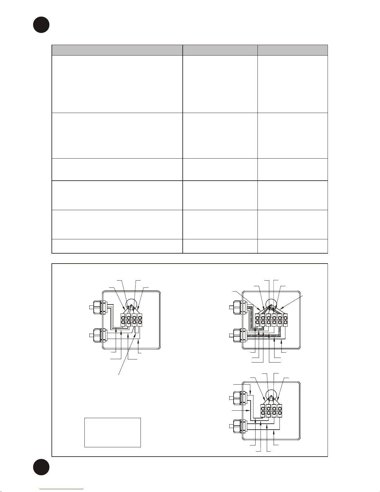
12
POWER
INPUT
230V/110V
TO MOTOR
11
BROWN
GREEN/YELLOW
BLUE
GREY or
BLACK
GREEN/YELLOW
BLACK
BROWN
GREEN/YELLOW
BLUE BLUE
GREEN/YELLOW
BROWN
RS485,
PC/PRINTER OUTPUT
(OPTIONAL)
TO LEVEL
PROBE CONTACT
(OPTIONAL)
3
RS485+
RS485 -
RED
ROSE
GREY
YELLOW
RED
ROSE
GREY
YELLOW
Max. current Motor
Imax = 6.5A (230 Vac)
Max. current Motor
Imax = 7A (110 Vac)
MC BOX 230Vac - 110Vac: EXTERNAL ELECTRICAL CONNECTIONS DIAGRAM
TO
PULSER
K600
TO NOZZLE
CONTACT
22
BROWN
WHITE
GREEN
BLUE
BROWN
WHITE
BROWN
BLUE
Apply a bridge
to the contacts
in the event that
there is no nozzle
contact
EN (Translated from Italian)

13
MC BOX 12Vdc - 24Vdc: EXTERNAL ELECTRICAL CONNECTIONS DIAGRAM
12V version MOTOR 12V
24V version MOTOR 24V
12V version 12V BATTERY
24V version 24V BATTERY
BLUE
BLACK
BROWN
BLUE
BLUE
YELLOW
12V version: TO POWER12V
RED
BLACK
YELLOW
RED
NOZZLE
CONTACT
85
86
87
30
YELLOW
BLUE
RED
BLACK
+
-
BATT IN
+
BATTERY
MOTOR
+
-
R-C
FILTER
If you want to use
the nozzle contact,
remove the jumper
If you wish to turn
the device on and off
with the vehicle key,
replace the jumper
with an ignition switch
The fuse (max. 40A @ 24V and max. 60A @ 12V)
can be placed on the motor or inside the electrical
box as shown. (See "Electrical Power" chapter).
Choose fuse size in accordance with the motor's
absorption level (See "Electrical Power" chapter).
24V version: TO POWER 24V
12V version: TO POWER RELAY 12V
24V version: TO POWER RELAY 24V
WHITE
RED
BROWN
ROSE
GREY
YELLOW
BROWN
WHITE
RED
ROSE
RS-485 +
RS-485 -
TO
K600
PULSER
RS485
PC/PRINTER
OUTPUT
(OPTIONAL)
LEVEL
CONTACT
ON-OFF
key
FUSE
XX
FUSE
XX
85
86
87
30
FUSE
XX
MOTOR
FUSE
XX
Max. current Motor
Imax = 50A (12 V)
Max. current Motor
Imax = 25A (24 V)
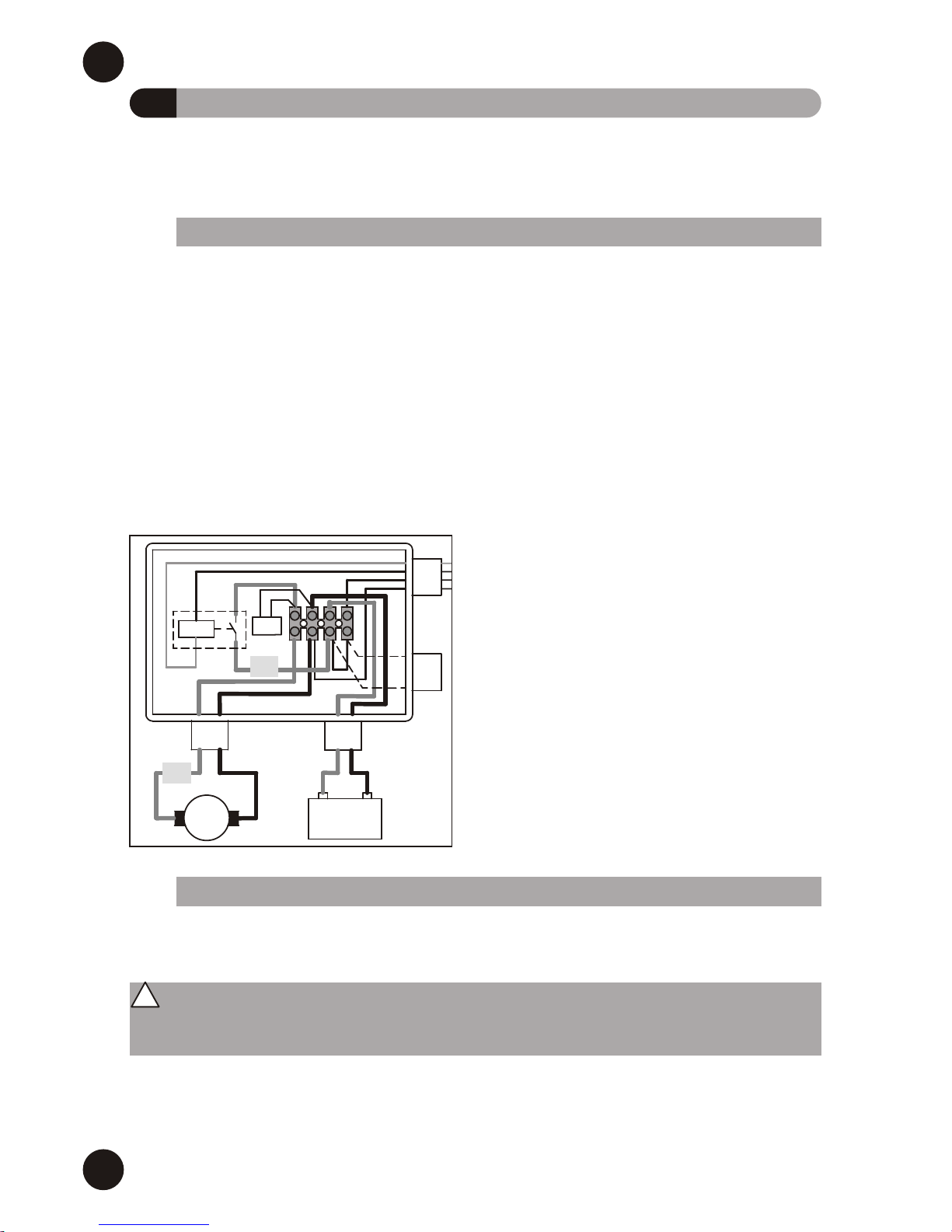
EN(Translated from Italian)

14
CPU CARD
DISPLAY CARD
KEY
READER
KEYBOARD
I/O CARD
BROWN
RED
GREEN
BLUE
1
2
3
4
5
6
1.
2.
3.
4.
5.
6.
KEY READER (I-BUTTON)
DISPLAY CARD
CPU CARD
KEYBOARD
I/O CARD
ELECTRICAL BOXES
K600
PULSER
NOZZLE
CONTACT
BLACKGREY
RED
ROSE
GREY
YELLOW
BLUE
GREEN
YELLOW
GREY
BROWN
WHITE
RED
ROSE
BLUE
YELLOW/GREEN
BROWN
VERSION 230V:
POWER IN 230V
VERSION 110V:
POWER IN 110V
RS-485 OUT TO
PC/PRINTER
(OPTIONAL)
TO LEVEL
PROBE CONTACT
(OPTIONAL)
BROWN
YELLOW/
GREEN
BLUE
GREY
BLACK
BROWN
WHITE
VERSION 230V: MOTOR 230V
VERSION 110V: MOTOR 110V
MC BOX 230Vac - 110Vac:
INTERNAL ELECTRICAL
CONNECTIONS DIAGRAM
EN (Translated from Italian)

15
CPU CARD
DISPLAY CARD
KEY
READER
KEYBOARD
I/O CARD
VERSION 12V:
POWER INPUT 12V
WHITE
VERSION 12V: MOTOR 12V
VERSION 24V: MOTOR 24V
85
86
87
30
+
-
IN BATT
-
+
BATTERY
MOTOR
+
-
OPTIONAL
(RS485 +
LEVEL PROBE)
K600
PULSER
LEVEL
CONTACT
BROWN
RED
ROSE
GREY
YELLOW
NOZZLE
CONTACT
BLACK
RED
BLUE
YELLOW
BROWN
BLUE
1
2
3
4
5
6
1.
2.
3.
4.
5.
6.
KEY READER (I-BUTTON)
DISPLAY CARD
CPU CARD
KEYBOARD
I/O CARD
ELECTRICAL BOXES
YELLOW
BLUE
BROWN
GREY
YELLOW
BROWN
WHITE
RED
ROSE
RED
BLACK
FILTER
R-C
VERSION 24V:
POWER INPUT 24V
VERSION 12V: BATTERY 12V
VERSION 24V: BATTERY 24V
VERSION 12V: RELAY 12V
VERSION 24V: RELAY 24V
BLUE
MC BOX 12Vdc / 24Vdc: INTERNAL ELECTRICAL CONNECTIONS DIAGRAM
The fuse (max. 40A @ 24V and max. 60A @ 12V)
can be placed on the motor or inside the electrical
box as shown
Choose fuse size in accordance with the motor’s
absorption level (see “Electrical Power” chapter)
(see “Electrical Power” chapter).
If you wish to turn the device on and off
with the vehicle key, replace the jumper
with an ignition switch
ON-OFF Key
FUSE
XX
FUSE
XX
85
86
87
30
FUSE
XX
MOTOR
FUSE
XX
Max. current Motor
Imax = 50A (12 V)
Max. current Motor
Imax = 25A (24 V)
EN(Translated from Italian)
16
I COMMISSIONING
To correctly commission the MC BOX the sequence of operations indicated below
must be followed and the MC control system functions must be known (see attached
manual).
Once the power connections have been made, the MC BOX can be energised by
means of the master switch to be fitted by the installer on the upstream line.
Switching on of the MC system will be indicated by the lighting up of the two backlit
LCDs fitted on the front.
NOTE:
In the event of continuous current power supply (DC), a fuse size that is appropriate
to the DC motor's absorption level should be introduced to the motor
power line.
For example:
• If the connected motor is one that absorbs 10A max then a 12A delay fuse should be
inserted.
• If, however, the motor absorbs 50A max, then a 60A delay fuse should be inserted.
• If the fuse is small, it can be fitted along
the cable inside the junction box, in
position (1) (see illustration)
• If, however, the fuse is very big (e.g. 60A)
and cannot physically fit inside the box,
then it can be inserted along the motor’s
power supply cable in position (2) (see
illustration)
I.1 ELECTRICAL POWER SUPPLY
85
86
87
30
+
-
BATT IN
-
+
BATTERY
MOTOR
+
-
FILTER
R-C
(1)
(2)
Every MC BOX station can be adapted to the specific requirements of the station
manager. To do this the MC control system must be CONFIGURED.
After completing configuration, user PIN CODES can be assigned to the persons
charged with using MC BOX, in accordance with the detailed information in the MC
manual.
I.2 STATION CONFIGURATION
EN (Translated from Italian)
MC configuration is crucial and must be done by skilled personnel.
To perform this operation, the MC manual must be carefully and thoroughly read.
! WARNING
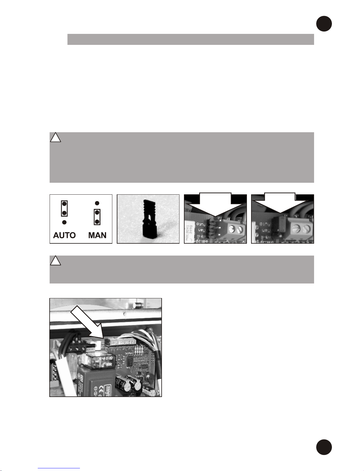
17
In MANUAL mode:
• The MC's LCD may be switched off (only the
backlight is clearly visible) or you may continue
to see the indication that was present at the
time of transition from AUTO to MAN.
• No PIN CODE is required to activate the
pump; the pump starts when the dispenser
nozzle is removed from its lodging and stops
when it is put back (naturally this is in the event
that the "nozzle contact" function is used).
• The amount dispensed is not shown in any
way.
All the MC BOX functions are controlled by the MC control system.
The MC system can nevertheless be disengaged for any startup or maintenance
activities requiring repeated pump starting.
In these case, it is often convenient to simplify pump startup by not having to enter any
code and record any dispensing data.
To do this, a JUMPER has been fitted on the card that permits switching from
AUTOMATIC mode (code request to access dispensing) to MANUAL mode (no code
request).
I.3 DISENGAGING THE “MC” SYSTEM
WITHOUT
JUMPER
JUMPER
IN POSIT.
AUTO
EN(Translated from Italian)
The jumper is only accessible by opening the front panel and is positioned as
shown in the photo.
In this operating mode, MC does not record any data relating to performed
dispensing operations.
Before accessing this jumper, the voltage must be removed.
! WARNING
Before accessing the electrical parts, be sure that you have disconnected all of
the general switches that power the device.
! WARNING

L EVERY DAY USE
Thanks to the MC control system, all the MC BOX models provide access to authorised
users only.
MC acknowledges User authorisation by means of two alternative systems:
• The entering of a 4-figure SECRET CODE (PIN CODE)
• The fitting of an electronic key (OPTIONAL)
18
Before using the MC BOX station, check the METER ACCURACY.
For this purpose, proceed as follows:
• Enter a previously enabled USER PIN code;
• Run the fuel into a calibrated container;
• Compare the quantity of dispensed diesel fuel using a calibrated container.
If accuracy is NOT satisfactory, proceed to CALIBRATE THE METER according to the
instructions in the specific manual.
I.4 METER CALIBRATION
EN (Translated from Italian)
To correctly check accuracy, always keep to the following instructions:
• Use a precision sample container, featuring a graduated scale, with a capacity
of at least 20 litres.
• Before making the check, always make sure you have eliminated all the air from
the system and then run the fuel until a full and regular flow is achieved.
• Dispense continuously at MC BOX maximum flow rate.
• Stop the flow by quickly closing the nozzle.
• Reach the graduated area of the sample container, avoiding prolonged
dispensing at low flow rate, but rather performing short dispensing operations
at maximum flow rate.
• Compare the reading provided by the container, with that provided by MC BOX,
after waiting for all the froth to disappear
! WARNING
Differences of up to 1/10 of a litre affecting the dispensing of 20 litres of fluid fall
within the guaranteed precision of +/- 0,5%.
! WARNING
All the users to whom a PIN CODE is assigned must be adequately instructed and
be at least acquainted with the contents of this chapter.
! WARNING
19
The pump will start (if previously enabled) just as soon as the control lever is moved
to ON position, while it switches off as soon as the control lever is moved to
OFF position.
No further manual operation is required to start or stop the pump.
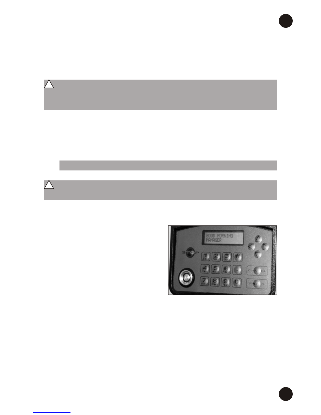
In the case of the simplest configuration (no optional data required), the fuel dispensing
procedure is the following:
• Insert PIN CODE
(or apply the electronic key)
If the MC recognises the activated PIN
(or key), a “GOOD MORNING MANAGER /
USER” message is displayed and the
pump enabled.
For details on dispensing options, please
refer to the M0187 manual.
L.1 FUEL DISPENSING
The configuration of the MC system permits requiring the User to enter further optional
data (vehicle licence plate, mileage, quantity to be dispensed).
For details, see the MC control system manual.
In the event that these options are not set, MC will recognise an activated PIN CODE
and, once the nozzle contact (if applicable) has been closed, the pump is enabled,
allowing it to dispense
EN(Translated from Italian)
Such enabling does not result in immediate pump startup.
The pump is in fact controlled by a switch (positioned in the nozzle seat)
operated by the user.
! WARNING
Fuel MUST ONLY be dispensed under the careful control of the User.
! WARNING

20
M ROUTINE MAINTENANCE
The MC system is maintenance free.
To control it however, refer to the dedicated M0187 manual provided.
M.1 “MC” CONTROL SYSTEM
M.2 TROUBLESHOOTING
EN
PROBLEM POSSIBLE CAUSES SOLUTIONS
AUTO/MAN jumper in the MAN.
position
The user has not yet been
configured by the system
MANAGER
The key has not been linked to
the User by the system
MANAGER
The electronic key is damaged
and is no longer recognised by
the system
The keyboard is damaged and
does not insert the data properly
The MC BOX does
not switch on
The MC BOX turns on
and the displays light
up but no words
appear
The MC BOX turns on
and the displays light
up but the words that
appear are irregular
and the system does
not respond to any
commands
The system does not
recognise the “USER”
with PIN CODE or
Electronic key
• Check connections
• Ensure disconnect switch is in
the ON position
• Check fuse
• Turn the vehicle key to the
ON position
Put the jumper to the AUTO
position
The system MANAGER sets up a
New User
The system MANAGER links the
key to the User
Change electronic key (contact
technical support)
Change keyboard (contact
technical support)
Power supply has failed due to:
• The power leads being
connected incorrectly
• The upstream circuit switch
being in the OFF position
• The power supply fuse being
interrupted
• For DC versions: vehicle key in
the OFF position (if the
“ignition on” power supply
option has been adopted)
(Translated from Italian)

21
PROBLEM POSSIBILE CAUSES SOLUTIONS
It has not been connected
properly to the set terminals
The Pulser that emits the count
signals has not been connected
properly
The Pulser that emits the count
signals is NOT compatible with
the electronics
The signal sent by the Pulser is
outside the acceptable electronic
ranges
Action not permitted by nozzle
contact
The MOTOR
will NOT START
DOES NOT COUNT
when dispensing
The count is
INACCURATE
The count remains
INACCURATE even
after calibration, or it
is accurate but only
for low flow rates
It DOES NOT
COMMUNICATE with
the PC
Check connections
Verificare collegamenti
An incoming electronic signal,
namely “clean contact” or
“OpenCollector”, should be
received.
If the input signal is an
incompatible voltage signal, the
electronic board is likely to be
damaged, in addition to the
malfunction
The maximum pulsation
frequency must be 70 Hz and
between 20% and 80% duty
cycle. The system does not
process received data correctly
outside the acceptable electronic
ranges.
The system must adapted to fit
within the correct ranges,
possibly by interposing other
electronic interface devices
(please contact Technical
Support for options)
Check how the nozzle contact
option has been set (YES/NO)
and the status of the relevant
jumper
The system is NOT calibrated
The RS485 connection is not
correct
The driver on the PC is not
installed properly or the version
is not compatible with the PC’s
Operating System
The RS232 or USB converter is
damaged
The PC's USB or RS232 port is
damaged
Calibrate the system according
to the procedure
Check the connections
Check the versions of the drivers
and the Operating System.
Contact Technical Assistance
Try with a different converter: if
the problem disappears, replace
the converter
Try a different port or try it on a
different PC to check the rest of
the device: if it works on another
PC, then the problem is with the
PC
EN(Translated from Italian)

22
85
86
87
30
+
-
BATT IN
-
+
BATTERY
MOTOR
+
-
FILTER
R-C
Fuse
XX
Fuse
XX
N SPECIAL MAINTENANCE
To check and replace contained fuses
• on the electronic boards
and/or
• in the junction box (for DC versions):
1) Remove voltage from the device;
2) Open the door to the MC BOX with the special key;
3) Open the junction box that contains the motor fuse (DC only) for verification and
possibly replacement;
4) Unscrew the metal back panel to access the electrical boards compartment;
5) Check the condition of the fuses and replace if necessary
6) Shut down everything and restore power.
N.1 CHECKING AND REPLACING FUSES
MOTOR FUSES
(AC Motors)
• 8 A T (Rit)
MOTOR FUSES
(DC Motors)
• The fuse (max. 40A @ 24V and
max. 60A @ 12V) can be placed
on the motor or inside the electrical
switch box (see “Electrical Power”
chapter)
Choose fuse size in accordance
with the motor’s absorption level
(see “Electrical Power” chapter).
POWER FUSE
• 100 mA T (Rit)
for the 230V / 50 Hz version
• 200 mA T (Rit)
for the 110V / 60 Hz version
• 1 A T (Rit)
for versions DC 12 Vdc and 24 Vdc
EN (Translated from Italian)

I
23
EN
The information contained in this manual is provided by the Manufacturer, who reserves
the right to make changes without prior notice
P MANUFACTURER AND SERVICE DATA
O MC BOX SPARE PARTS
5
15
3
14
6
1
4
4
8
2
2
7
9
10
11
12
13
7
13
MANUFACTURER:
DOCUMENT TYPE:
EDITION:
PRODUCT:
MODEL:
CONFORMITY:
TECHNICAL SUPPORT:
PIUSI S.p.A.
General Description and Instructions for Its Installation,
Activation, Use and Maintenance
Bullettin M0188A EN - Rev. 1
Diesel fuel dispenser for private use with meter
All the models of the MC BOX range, with singlephase/three-phase mechanical/electronic meter, with
various voltages/frequencies
CE Mark
(see Declaration of conformity, page 4)
Provided by the Service Departments of our Authorized
Resellers
(Translated from Italian)

Authorized reseller’s stamp
M0188A EN - Rev. 1
 Loading...