

Pittsburgh Modular Foundation 3.1, Foundation 3.1+ Move [208], Foundation 3.1 Move [104] Manual And Patch Manual
Page 1
PITTSBURGH MODULAR
FOUNDATION 3.1 and 3.1+
SYNTHESIZER
MANUAL AND
PATCH GUI DE
1
Page 2

Important Instructions – PLEASE READ
Read Instructions:
Please read the Foundation 3.1 Synthesizer manual completely before use and retain for future reference.
IMPORTANT Ribbon Cable Power Information:
The Foundation 3.1 combines a set of individual modules to create a complete instrument. The individual modules can be
rearranged, removed, and replaced with any compatible eurorack modules from Pittsburgh Modular and other manufacturers.
The Foundation 3.1 uses a standard eurorack power rail to connect the modules to the internal bipolar +/-12v power supply.
Please pay very close attention to the orientation of the ribbon cable when adding and removing modules. The stripe on the ribbon cable marks -12v. This
stripe needs to line up with the -12v pins on the power rail and the -12v pins on the module. Failure to match up the pins correctly can result in damage to
one or all the modules in the Foundation. On the power rail, the -12v pins are clearly labeled. On the individual modules, the positive and negative sides of
the pin connectors are labeled next to the power header on either the top or bottom of the PCB.
Do NOT remove individual modules from the Foundation while synthesizer is plugged in.
Do NOT unplug ribbon cables from the Foundation or individual modules while the Foundation is plugged in.
2
Page 3

Table of Contents
Important Instructions ………………….…… 2
Table of Contents …….…….…………….…… 3
Case and Power Specifications ………….… 4
Foundation Package Contents………….…… 4
An Introduction to Modular Synthesis….… 5
Modular Signal Paths ……………..........….. 6
Individual Modules ……………………..… 7-19
Patching a Modular Synthesizer ……..…. 20
Patch Guides …………………….….…… 21-38
Installing Modules……………..……….…… 39
Trimming Plastic Blank Panel….…….…… 40
1 Year Limited Warranty……………….…... 41
Service and Other Information ….….…… 42!
3
Page 4
Case and Power Specifications
Foundation 3.1 Package Contents
1x Foundation 3.1 Modular Synthesizer
1x Pittsburgh Modular Patch Cable Kit
1x External Power Adapter
Foundation 3.1 Move [104] Case and Power Supply Info
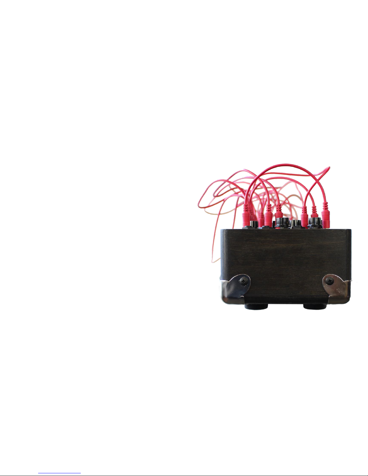
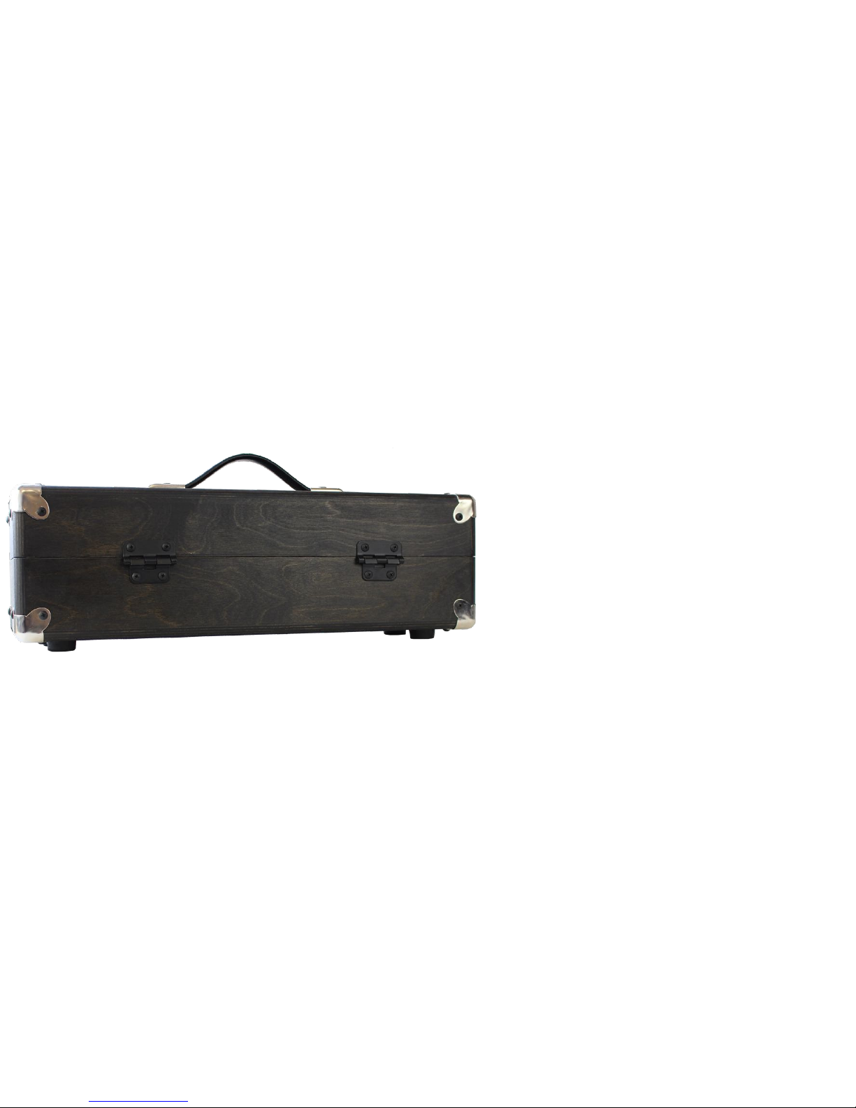
External Dimensions Including Removable Lid: 23.5” x 6.25” x 7”
104hp Move [104] Black Eurorack Case
Sliding Square Nut Mounting System with 20 Nuts Per Rail
External Power Adapter Connection: 2.1mm Barrel Type
External Power Adapter Output: 12V-15V AC / 2000mA
Foundation 3.1+ Move [208] Case and Power Supply Info
External Dimensions Including Removable Lid: 23.5” x 12” x 7”
208hp Move [208] Black Eurorack Case
Sliding Square Nut Mounting System with 20 Nuts Per Rail
External Power Adapter Connection: 2.1mm Barrel Type
External Power Adapter Output: 15V DC / 4000mA
4
Page 5
An Introduction to Modular Synthesis
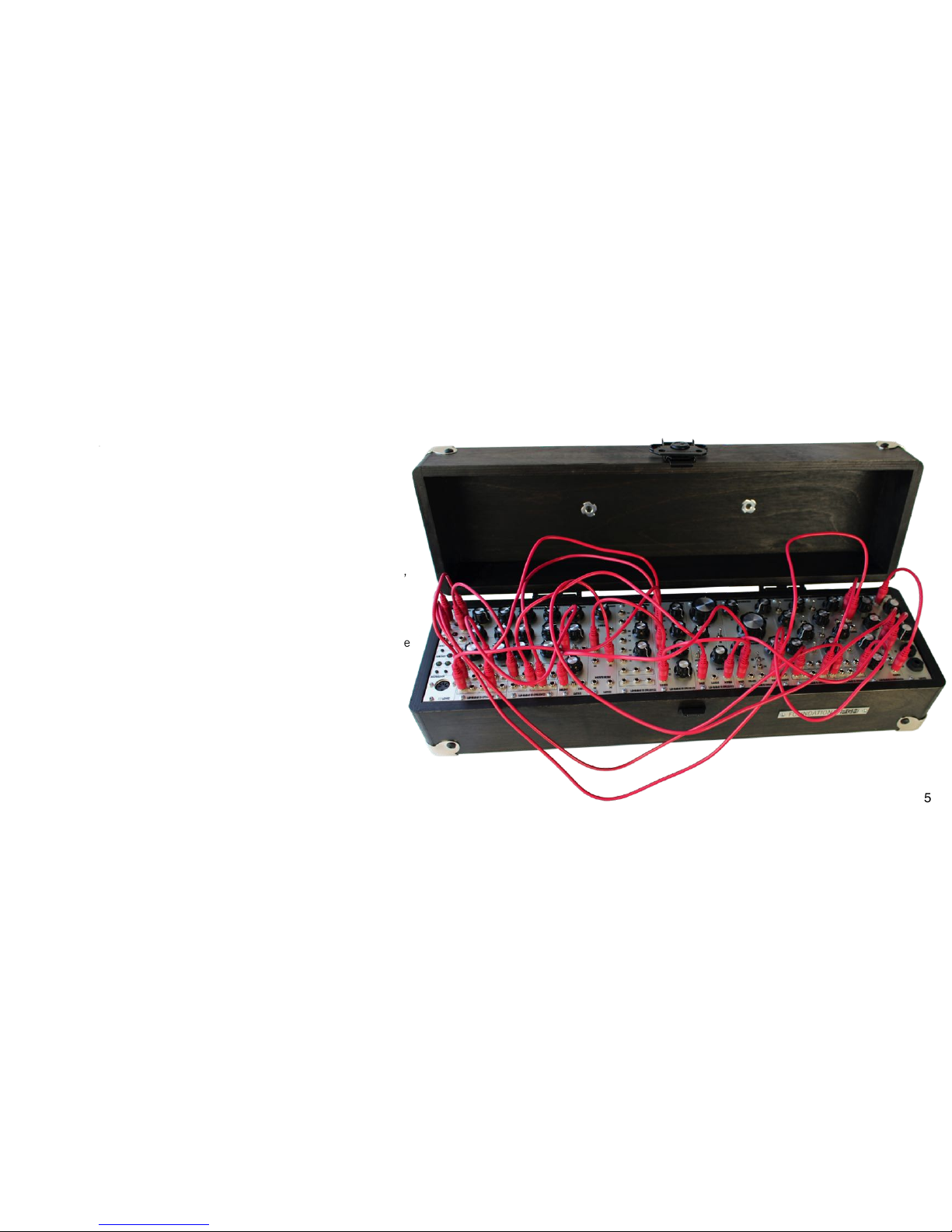
A complete, fully modular analog synthesizer, the Foundation 3.1 is
a modern version of the great 1970's monosynths, conveniently
broken down into individual components with no hardwired signal
flow to restrict experimentation. Oscillators, mixer, filters, envelope,
VCAs, etc., are all individual modules.
Because each module performs a single function, without patch
cables the Foundation will not produce sound. A synthesizer voice
must first be patched up using cables to wire modules together. The
Foundation allows the signal flow to be rewired with every patch.
The voice can be as simple as listening to the triangle output of
an oscillator or as complex as a self running patch using all the
modules.
5
Page 6
Modular Signal Paths
The Foundation signal path is divided into two types of signals: audio signals and control voltages.
The audio signal is the sound that is produced. The audio signal path starts at a sound source such as a Waveforms oscillator, LFO running at audio rate,
or the Filter in oscillator mode. The audio signal is then patched through other modules used to shape the sound such as mixers, filters, and
amplifiers.
Control voltages (CV) manipulate the audio signal in several different ways.
Gates are represented by a high or low control voltage. A gate can be generated using a square or pulse wave from an
oscillator or LFO, or by using the GATE output from the Midi 3 module. A gate can be shaped using an
envelope generator to control the attack, decay, sustain, and release of the gate. The modified gate signal
can then be sent to any CV input on the Foundation.
A second use for control voltages is as a modulation source. For example, a control voltage from the CV
output of the Midi 3 module patched into the 1V/O input on the Waveforms oscillator module controls
the frequency of the oscillator based on the midi note received. The LFO2 module provides two
separate low frequency oscillators that make perfect control voltage modulation sources. Audio
signals also make a great control voltage source for oscillator FM (frequency modulation).
As always, experimentation is essential to getting the most out of the Foundation.!
6
Page 7
Individual Modules
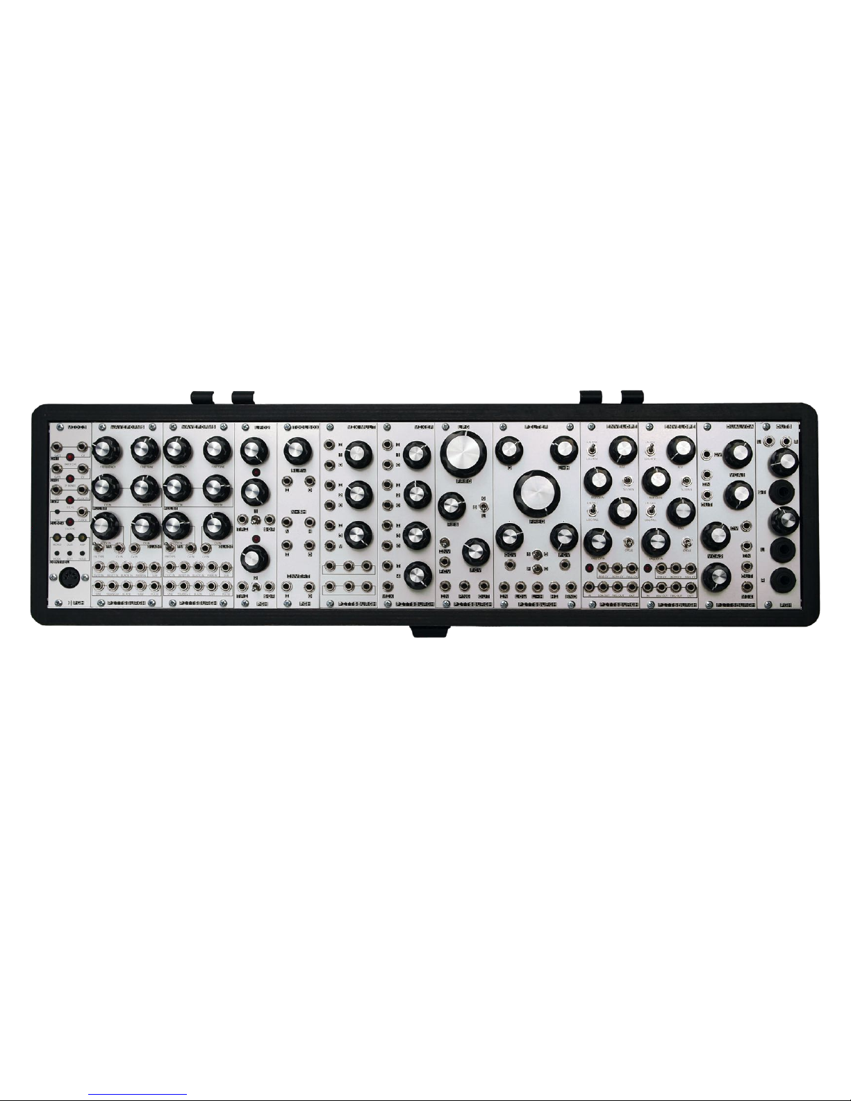
The Foundation is a collection of 13 modules that will allow you to create complex analog sounds. The modular nature of the Foundation allows for deep
experimentation and a virtually unlimited sound palate. The following pages describe the functionality and controls of each module.!
7
Page 8
Midi 3 Module
Description
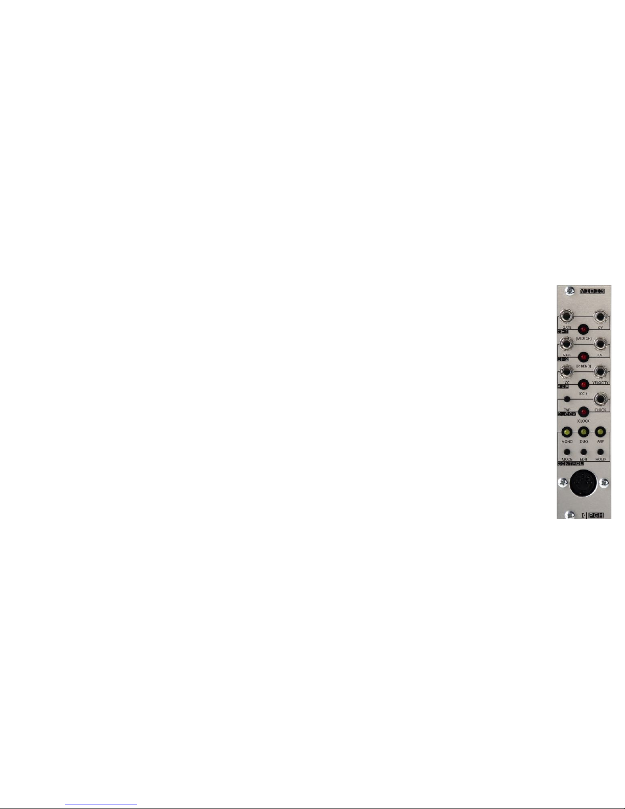
A midi to cv module converts standard midi note messages into the analog control voltages used by modular and other analog synthesizers.
This allows the synthesizer to be controlled by a midi keyboard, sequencer, or DAW. The two CV outputs on the Midi 3 can be used to control
the pitch of an oscillator, cutoff frequency of a filter, or any other function that requires a control voltage signal. The set of Gate outputs on
the Midi 3 can be used to trigger envelope generators or other modules expecting a gate or clock source.
The Midi 3 is our third generation Midi to CV converter packed with a robust list of features. It includes the most complete set of mono and
duophonic midi response modes available in a eurorack module, assignable CC and dedicated velocity outputs, a feature rich clock source
with tap tempo, midi and external gate clock dividers, and multiple arpeggiator responses.
The Midi 3 is a deep module that can not be covered completely in the small amount of space allotted in this manual. Please download the
standalone Midi 3 manual for a complete detailed description of all the features and settings. The Midi 3 manual is available for download
from the Midi 3 web page. http://pittsburghmodular.com/midi3/!
8
Page 9
Waveforms Module x2
Description
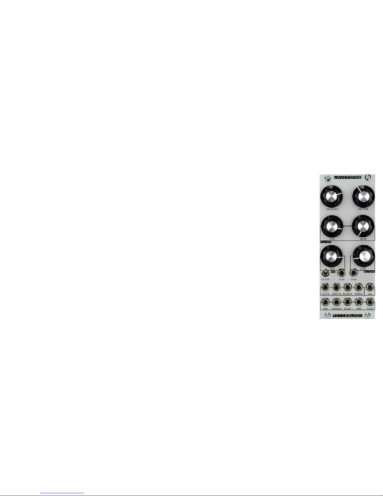
A wide range, multiple waveform generator. The Waveforms oscillator has a frequency range starting as low as 7 seconds per cycle,
allowing it to double as a voltage controlled LFO.
Controls
Frequency Control – Course frequency setting.
Fine Tune Control – Fine tune frequency setting.
Pulse Width CV Attenuator – Controls the amount of CV used to adjust the pulse width of the pulse wave.
Pulse Width Control – Manually controls the pulse width of the pulse wave.
FM CV Attenuator Control and Input – Frequency modulation CV input and attenuation control.
FM Type – Switches FM response type between linear and exponential.
Blade CV Attenuator Control and Input – Blade wave Y-axis modulation CV input and attenuation control.
1v/o Input – CV input used to track the oscillator at 1 volt per octave.
Reset Input – CV Input used to hard reset the Oscillator on the falling edge of the incoming waveform.
Blade Input – CV or audio rate input used to modulate the blade wave creating a ring mod type effect.
PWM Input – Pulse width modulation CV input. Affects the pulse width of the pulse wave.
Sub Output – Square wave sub oscillator output. Sub Oscillator is 1 lower than the oscillator core.
Sine Output – Sine wave output.
Triangle Output – Triangle wave output.
Blade Output – Blade wave output.
Saw Output – Saw wave output.
Pulse Output – Pulse wave output.!
9
Page 10
LFO2 Module
Description
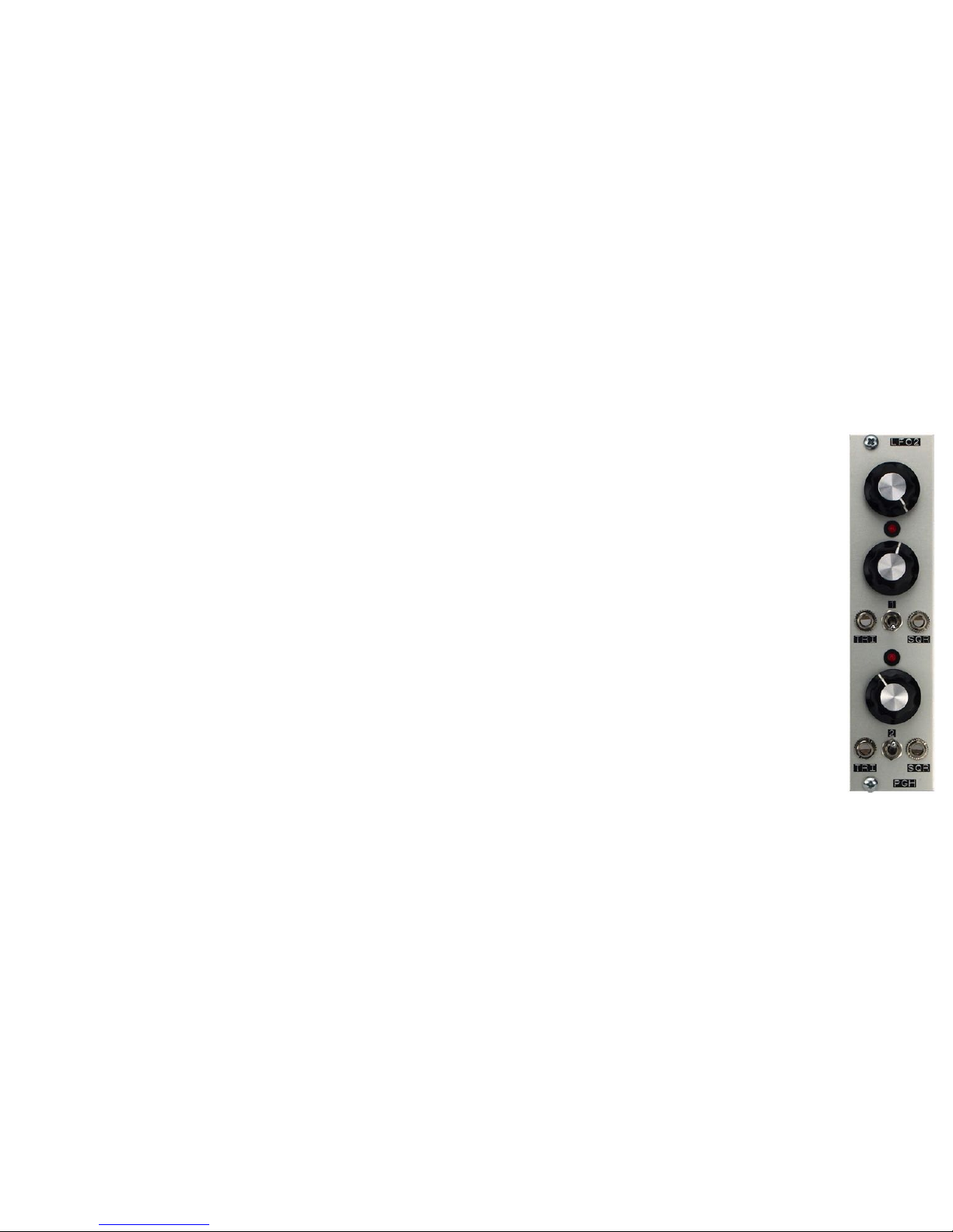
A dual low frequency oscillator module. It uses two different types of low frequency oscillator circuits to provide a variety of CV and audio
rate modulation options. The top LFO utilizes rate and symmetry controls to generate shifting waveforms. Adjusting the symmetry control
varies the shape of the TRI output waveform from a saw tooth to triangle to ramp wave. The symmetry control also adjusts the pulse width
of the SQR wave output. The bottom LFO is a simple triangle based low frequency oscillator with rate control over the triangle and square
outputs.
LFO 1 Controls (top)
Rate Control – Coarse frequency setting.
Symmetry Control – Modify the shape of the waveforms.
TRI Output – Saw / Triangle / Ramp wave output.
Range Switch – Switches the frequency range.
SQR Output – Square / Pulse wave output.
LFO 2 Controls (bottom)
Rate Control – Coarse frequency setting.
TRI Output – Triangle wave output.
Range Switch – Switches the frequency range of LFO 2.
SQR Output – Square wave output.
10
Page 11
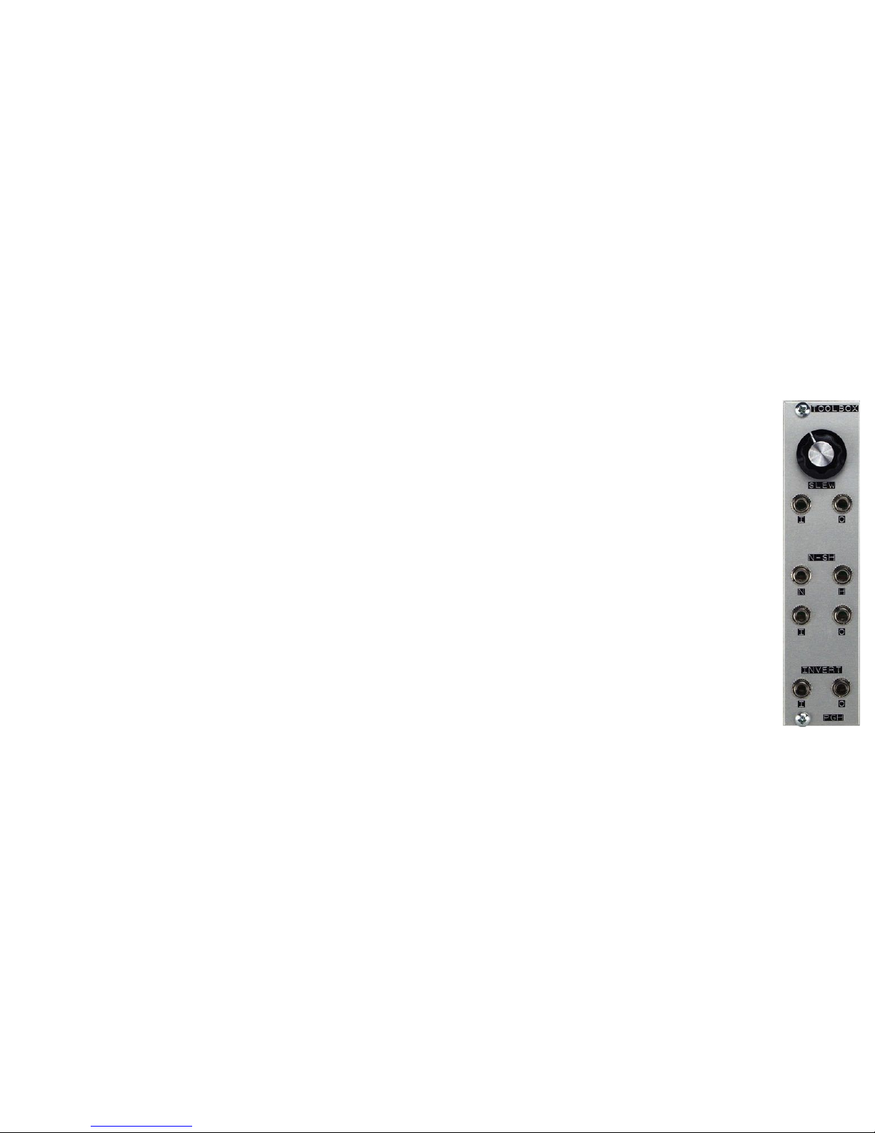
Too lb ox Module
Description
Multi-purpose slew, noise, sample & hold, and voltage inverter module. The slew control smoothly shifts from variable voltages creating a
portamento or glide effect. This function works well patched between the CV output of the Midi 3 and the 1v/o input of the Waveforms
oscillator. The Sample & Hold samples the voltage patched to the input and outputs that voltage until a new sample voltage is taken. A sample
is taken when the Hold input receives a positive gate or trigger. The invert function is a simple voltage inverter. Send a positive 3 volts in and
receive -3 volts from the output.
Slew Controls
Amount Control – Controls the amount of glide between voltages.
Slew Input – Voltage input.
Slew Output – Slewed voltage output.
Noise / Sample & Hold Controls
N Output – Noise output.
H Input – Hold input.
I Input – Sample input.
O Output – Sample and hold output.
Invert Controls
I Input – Voltage input.
O Output – Inverted voltage output.
11
Page 12
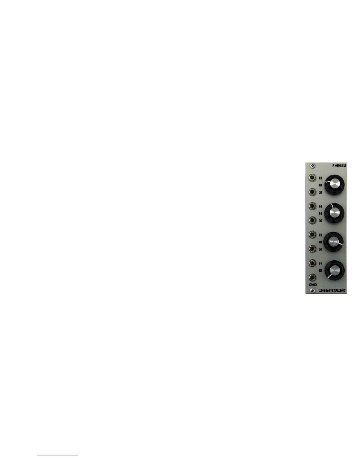
Mixer Module
Description
A flexible, low-noise four channel mixer and/or attenuator for audio and CV that can be used in several ways.
Three of the four channels have an output that removes the channel from the mixer circuit and allows it to become a standalone
attenuator. The pots are wired with a logarithmic volume curve that is tuned for use with audio but it will work with CV as well.
Patching the output of channel 1, 2, or 3 will remove it from the mixer circuit. Channel 4 cannot be removed from the mixer circuit,
however if channel 1, 2, and 3 are all being used as attenuators, channel 4 is the only input remaining in the mixer allowing it to be
used as a buffered attenuator.
The Mixer can be used as a…
4 Channel Mixer
4 Independent Attenuators
2 Attenuators and a 2 Channel Mixer
1 Attenuator and a 3 Channel Mixer
12
Page 13
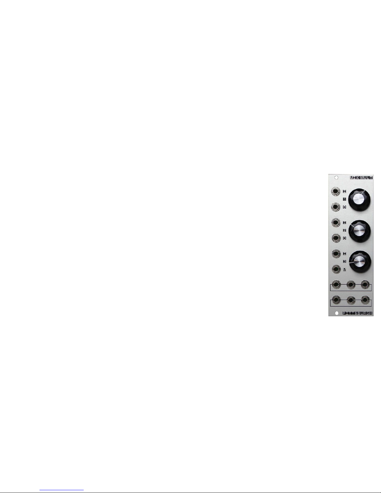
MixMult Module
Description
The MixMult is a multi-function module. The top section is a flexible, low-noise three channel mixer and/or attenuator for audio and CV
that can be used in several ways. The bottom section contains 2 sets of passive multiples.
Two of the three mixer channels have an output that removes the channel from the mixer circuit and allows it to become a standalone
attenuator. The pots are wired with a logarithmic volume curve that is tuned for use with audio but it will work with CV as well.
Patching the output of channel 1 or 2 will remove it from the mixer circuit. Channel 3 cannot be removed from the mixer circuit, however
if channel 1 and 2 are all being used as attenuators, channel 3 is the only input remaining in the mixer allowing it to be used as a
buffered attenuator.
The mixer section can be used as a…
3 Channel Mixer
2 Channel Mixer and 1 Attenuator
3 Independent Attenuators
The bottom of the module contains two sets of passive multiples. Patching a signal into one of the multiple jacks will split the signal to
the remaining two jacks, allowing a single audio or CV signal to be used in two places at once.
13
Page 14
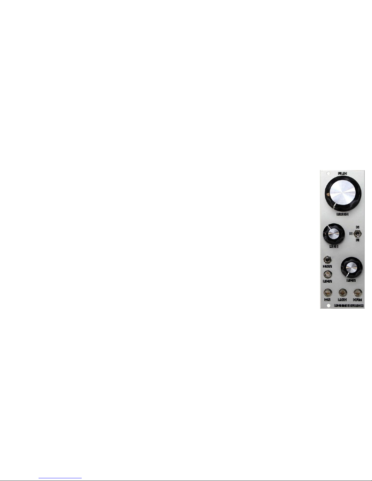
Lopass Gate Module
Description
The Lopass Gate module is a multi-mode filter/VCA combo module split into lopass gate, filter, and VCA modes. The lopass gate mode
is unique in the way that it simulates the characteristics of natural instruments. Louder sounds contain more harmonic content and
quieter sounds contain less harmonic content. Lowpass filter mode adds a resonance control creating a modern, aggressive filter sound.
The VCA is an extremely clean, quiet voltage controlled amplifier.
Controls
Frequency Control – In filter mode, the frequency knob controls the center frequency of the filter. In VCA mode, the frequency knob
controls the pass through signal level. In lopass gate mode, the frequency knob controls both the center frequency of the filter and the
pass through signal level.
Resonance Control – In filter mode, the resonance knob controls the amount of resonance. In VCA mode and lopass gate mode, the
resonance knob is not active.
Mode Switch – Switch between G (Gate/VCA), B (Both/Lowpass Gate), and L (Low pass filter) modes.
FM CV Attenuator Control and Input – Frequency modulation CV input and attenuation control.
Invert Switch – Inverts the FM CV signal from positive to negative or negative to positive.
IN – Audio signal input.
PNG – Gate or trigger input used to ping the vactrol and quickly modulate the frequency of the module.
OUT – Audio signal output.
14
Page 15
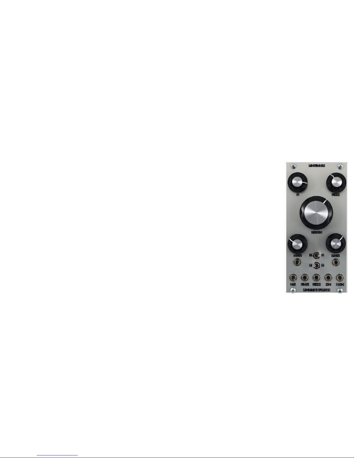
Filter Module
Description
The Filter is a voltage controlled, analog, state variable filter. State variable topology produces a very smooth and natural
sounding filter, in addition to offering several other modes of operation, each with a sound and energy all their own.
The Filter defines the sound of Pittsburgh Modular. It offers a warm, organic sweep through the full frequency range. The
lowpass filter is gummy and relaxed while the highpass is clean and defined. The goal was to produce a filter that did not have
a sweet spot; where the every turn of the frequency knob produced something interesting.
Modes of Sound
Multiple filter responses are available simultaneously including lowpass, highpass, and bandpass. The fourth filter response is
a variable response that shifts between lowpass, notch, and highpass.
Switch It Up
Two switches, Gain and Mode, further expand the capabilities of the Filter. The Gain switch modifies the functionality of the Q
while the Mode switch toggles between filter and oscillator modes. Setting the Gain switch to "1" conver ts the Q setting into a
VCA circuit for the audio input. !Switching the Gain switch to "Q" returns the standard filter Q response.
15
Page 16
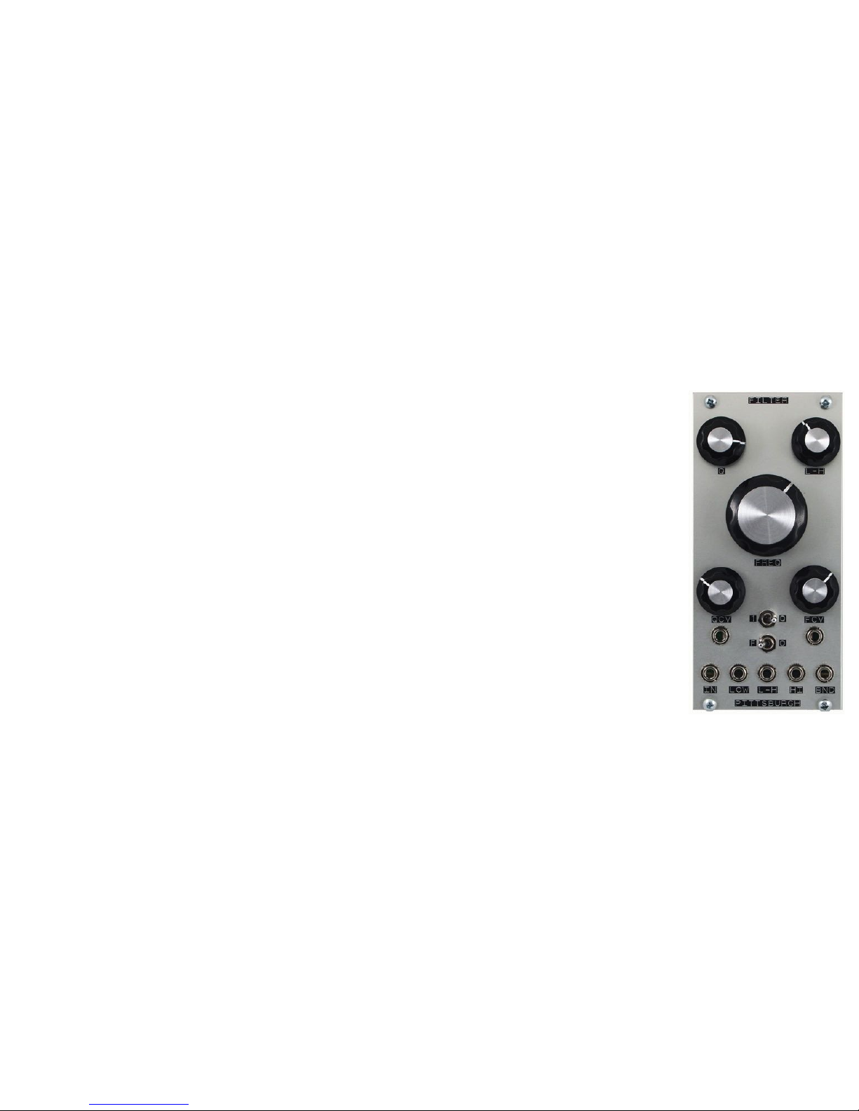
Filter Module (continued)
Switch It Up (continued)
Mode switches between Filter and Oscillator modes. Set to "Filter", the Pittsburgh Modular Filter will not self oscillate. Set to
"Oscillator" the Filter produces a high quality voltage controlled sine wave. Adjusting the Q while in Oscillator mode !modifies
the shape of the waveform. At more extreme settings the Q adds anything from warm fuzz to heavy distortion to the incoming
audio.
Controls
Q Control –!Adjusts the resonance (Q) of the filter.
FREQ Control –!Adjusts the Frequency of the filter.
L-H Control –!Sweeps between lowpass, notch, and highpass filters.
QCV Control and Input –!Resonance (Q) control voltage input and attenuver ter.
FCV Control and Input – Frequency control voltage input and attenuverter.
1-Q Switch –!Switch between Gain to 1 (VCA Mode) and Gain of Q (Standard Mode).
F-O Switch –!Switch between Filter and Oscillator Modes.
LOW Output –!Lowpass Output.
L-H Output –!Output based off of the L-H Pot.
HI Output –!Highpass Output.
BND Output – Bandpass Output.
16
Page 17
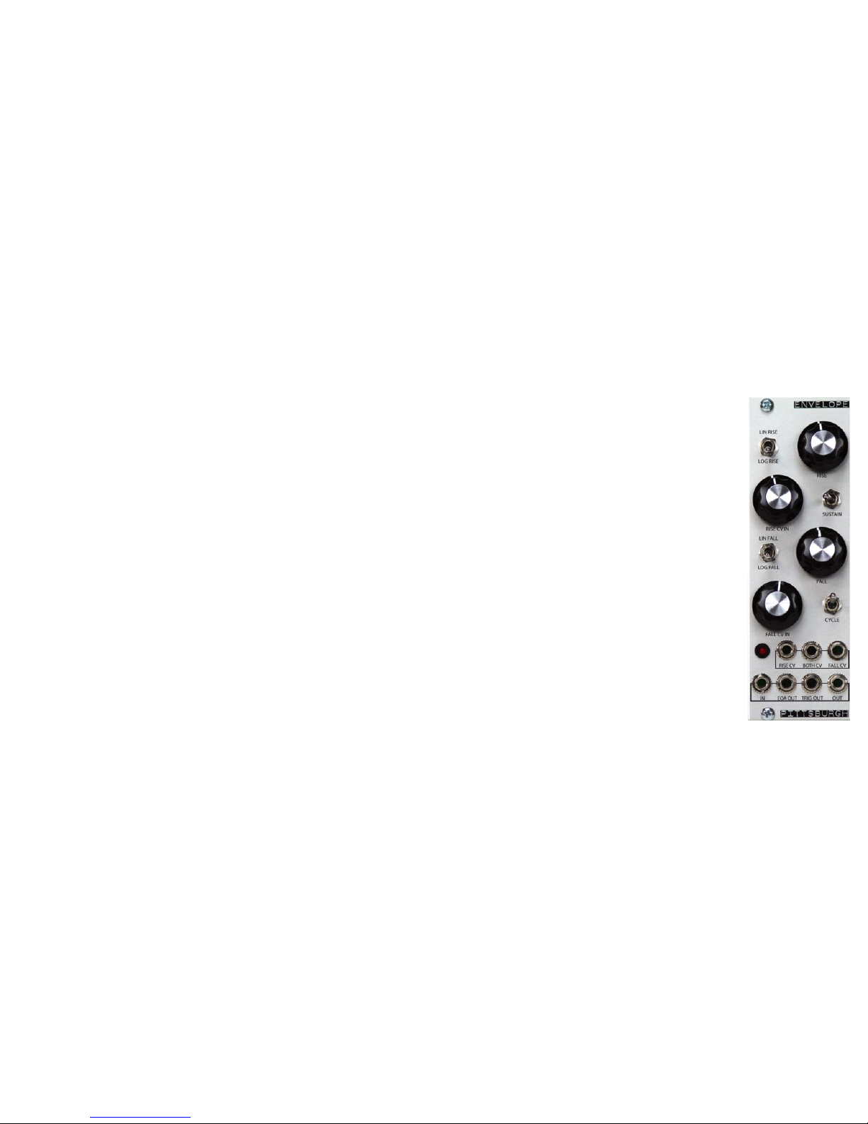
Envelope Module x2
Description
The Envelope is a complex multi-stage envelope generator with voltage controllable rise and fall. Using the sustain switch to toggle
between modes, the Envelope functions as either a 2 stage attack-decay envelope or a 3 stage attack-sustain-release envelope. This
module can perform as a voltage controlled envelope generator, slew (portamento), envelope follower, VCO and LFO, pulse delay, wave
shaper, and more.
Controls
Rise Response Switch – Switch between linear (up), and non-linear (down) response curve for rise.
Rise Control – Adjust the rise portion of the envelope. Left (short response). Right (long response).
Rise CV In Attenuverter - Attenuverter for Rise CV In. Also functions as log/lin/expo response control.
Sustain Switch - Enable (right) or disable (left) envelope sustain.
Fall Response Switch - Switch between linear (up), and non-linear (down) response curve for fall.
Fall Control - Adjust the fall portion of the envelope. Left (shor t response). Right (long response).
Fall CV In Attenuverter - Attenuverter for Fall CV In. Also functions as log/lin/expo response control.
Cycle Switch - The envelope will retrigger at the end of the fall stage. Creating a cycling envelope or LFO.
Rise CV Input - Rise CV input.
Both CV Input - Joint Rise and Fall CV input.
Fall CV Input - Fall CV input.
In - Main signal input.
EOA Output - Gate signal output. Signal goes high at end of rise.
Trigger Output - Trigger output. Trigger created at end of fall.
Output - Main signal output.!
17
Page 18
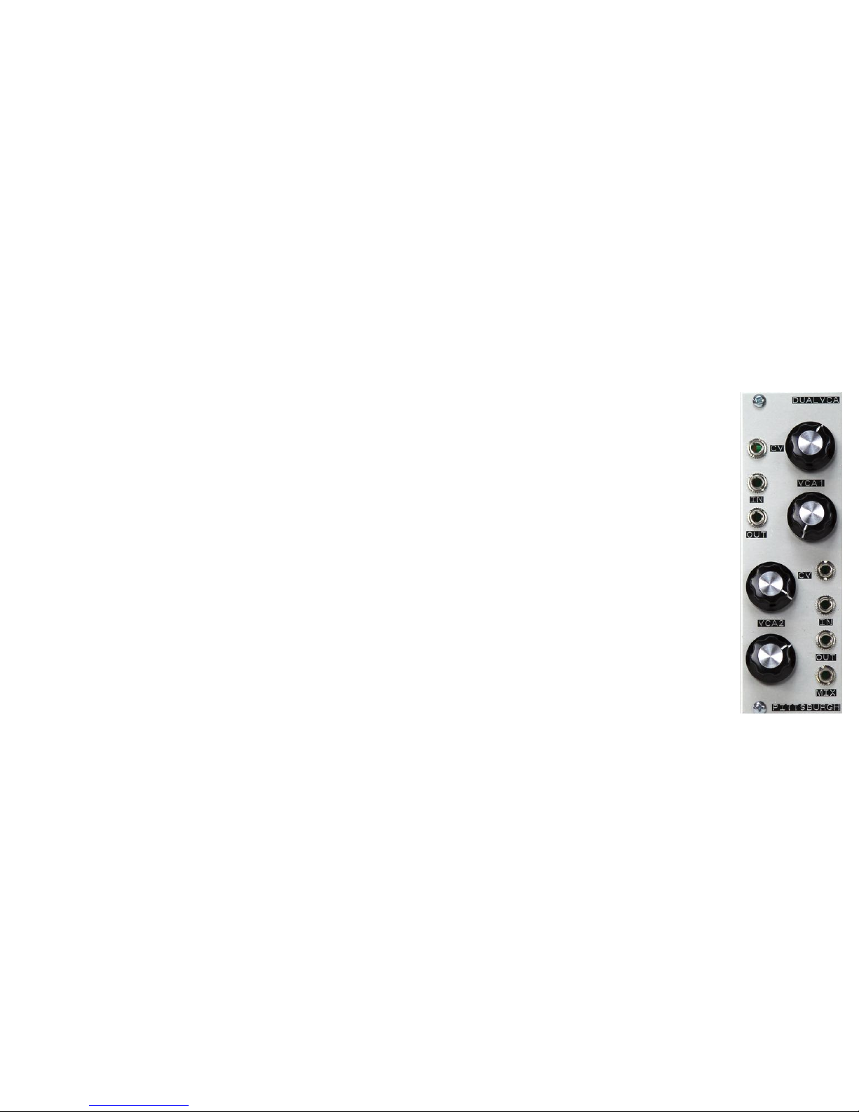
Dual VCA Module
Description
The Dual Index is a dual linear voltage controlled amplifier (VCA) and a two channel voltage controlled mixer. !It has two standalone VCAs
and a fully buffered mix output. !Each channel offers offset gain and CV attenuation. The CV and IN of channel 2 are normaled to
channel 1. !If left unpatched, channel 2 will operate using the channel 1 CV and IN signals.
Controls
Index 1 (VCA 1):"
CV – CV Input used to control the VCA."
CV Control – CV input attenuator."
In – Signal input."
Out – Signal output.
Index 2 (VCA 2):!
CV – CV Input used to control the VCA."
CV Control – CV input attenuator."
In – Signal input."
Out – Signal output.
Mix – Fully Buffered mix of the VCA 1 and VCA 2 outputs.
18
Page 19
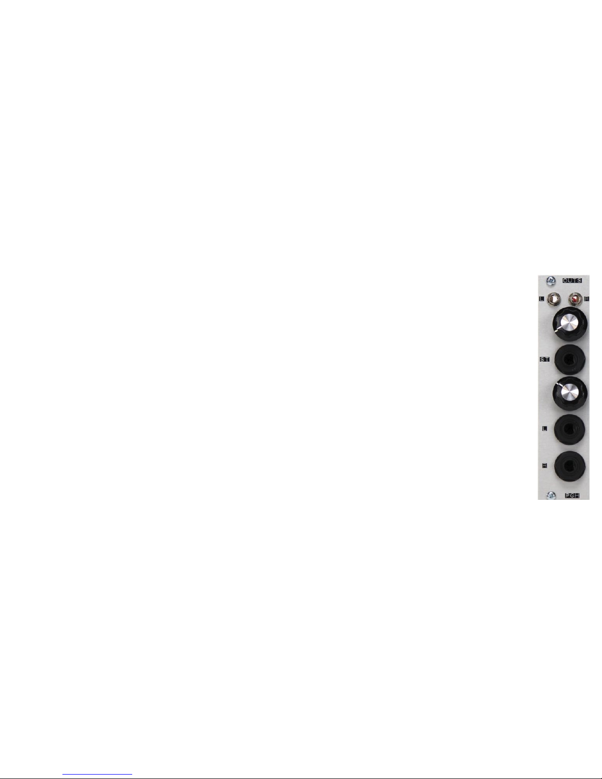
Outs Module
Description
A simple way to get sound out of the Foundation. Outs is a dual independent output module featuring a stereo 1/4" headphone amplifier
output and dual mono 1/4" line level outputs."
"
Left and Right inputs are available. If only the left input is used, the signal is sent to both the Left and Right outputs.
19
Page 20
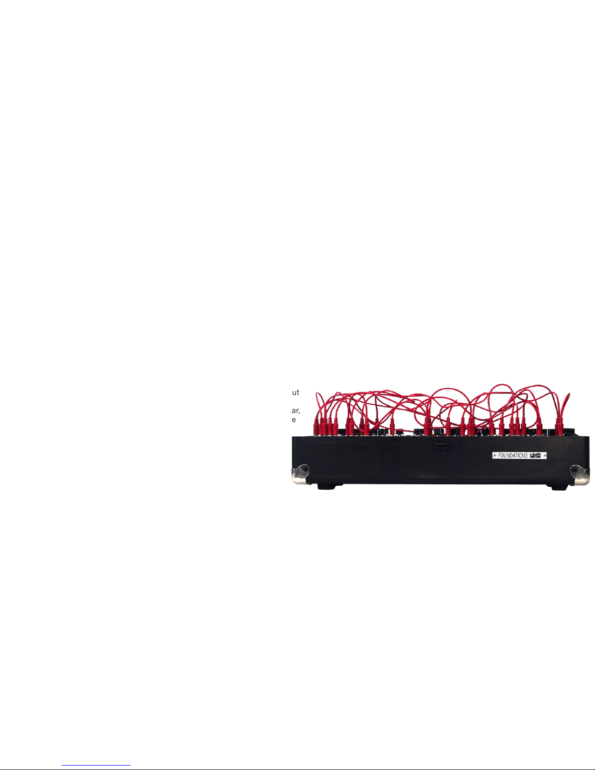
Patching A Modular Synthesizer
The following pages contain many examples of how to patch the Foundation 3.1. These examples showcase the flexibility of the Foundation and highlight as
many features from each module as possible. Use the patches provided as a teaching tool. Once you have set up a patch, adjust knobs and remove cables
from the Foundation while referencing the module description pages within the manual. This will help you develop an understanding of what function each
part of the patch is performing. Red patch cables are CV signals. Green patch cables are audio signals. The blue dots represent the relevant control settings.
These dots are meant to represent a starting point and are not definitive settings. Experimentation is essential.
The patch guide provides at least one "Module Test Patch” for each module within the Foundation. These patches showcase the core functionality as well as
additional features of the highlighted module. In general, the test patches will provide a way to focus attention on the capabilities of a single module and may
not provide results that would be considered musical.
Working with individual modules can be fun but the true power of any modular
synthesizer comes when different modules start to interact. Patching the output
of one module to the input of another is a fundamental part of modular
synthesis. Even though the Foundation 3.1 is designed to be a tabletop modular,
the patches can become complex quickly. Any output on the Foundation can be
patched to any input. Understanding the capabilities and functionality of
each module will allow even the most complex patches to be understood
easily.
If you come up with a good patch, we want to try it! Send all your
interesting patches to [email protected].
20
Page 21
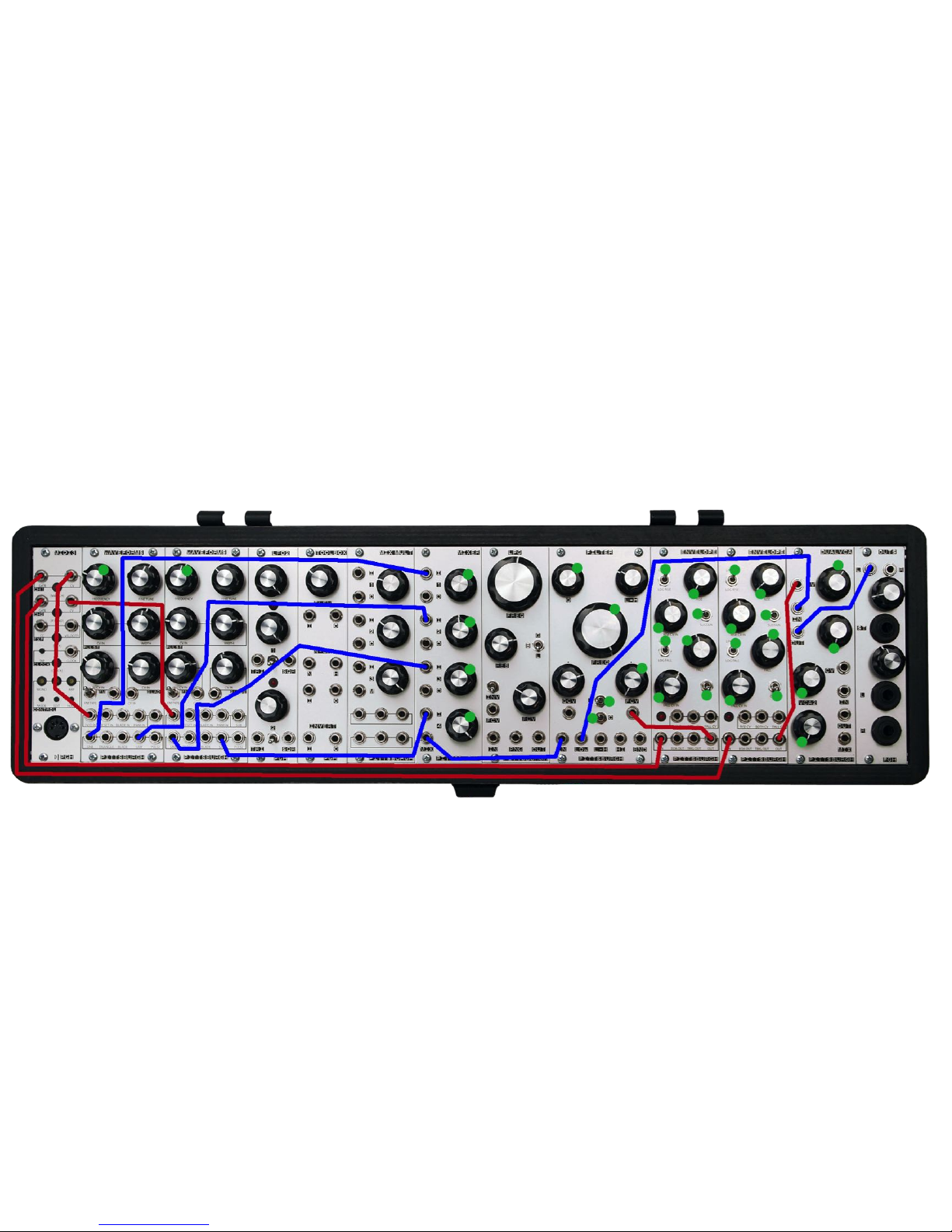
Vintage Monosynth Patch
Description - Monophonic Starting Point
Notes - Use this patch as a starting point for huge bass and classic leads.!
21
Page 22
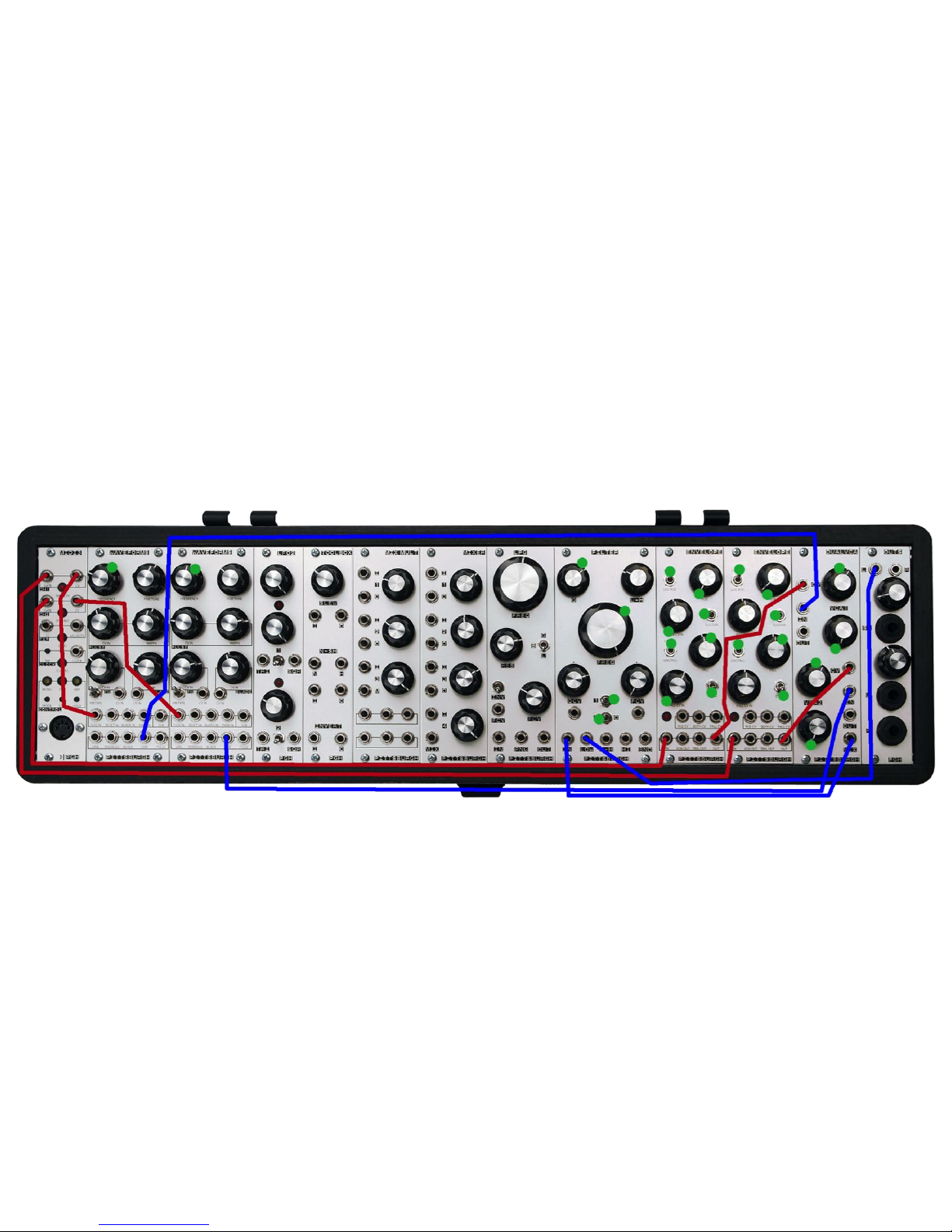
Duophonic Synthesizer Patch
Description - Basic Duophonic Starting Point
Notes - Use this patch as a starting point for a duophonic synthesizer.!
22
Page 23
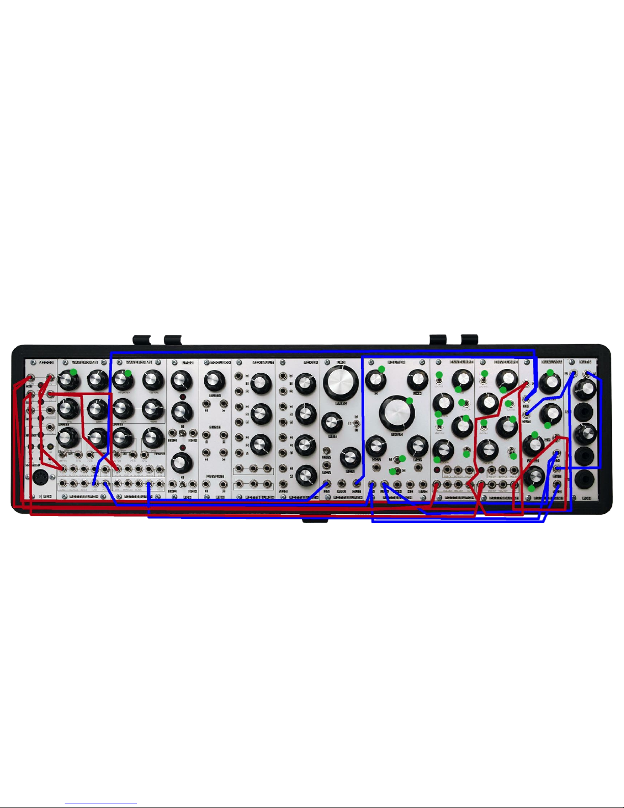
Dual Monophonic Synthesizers Patch
Description - Basic Dual Monophonic Synthesizer Starting Point
Notes - Use this patch as a starting point for creating two independent synthesizers.!
23
Page 24
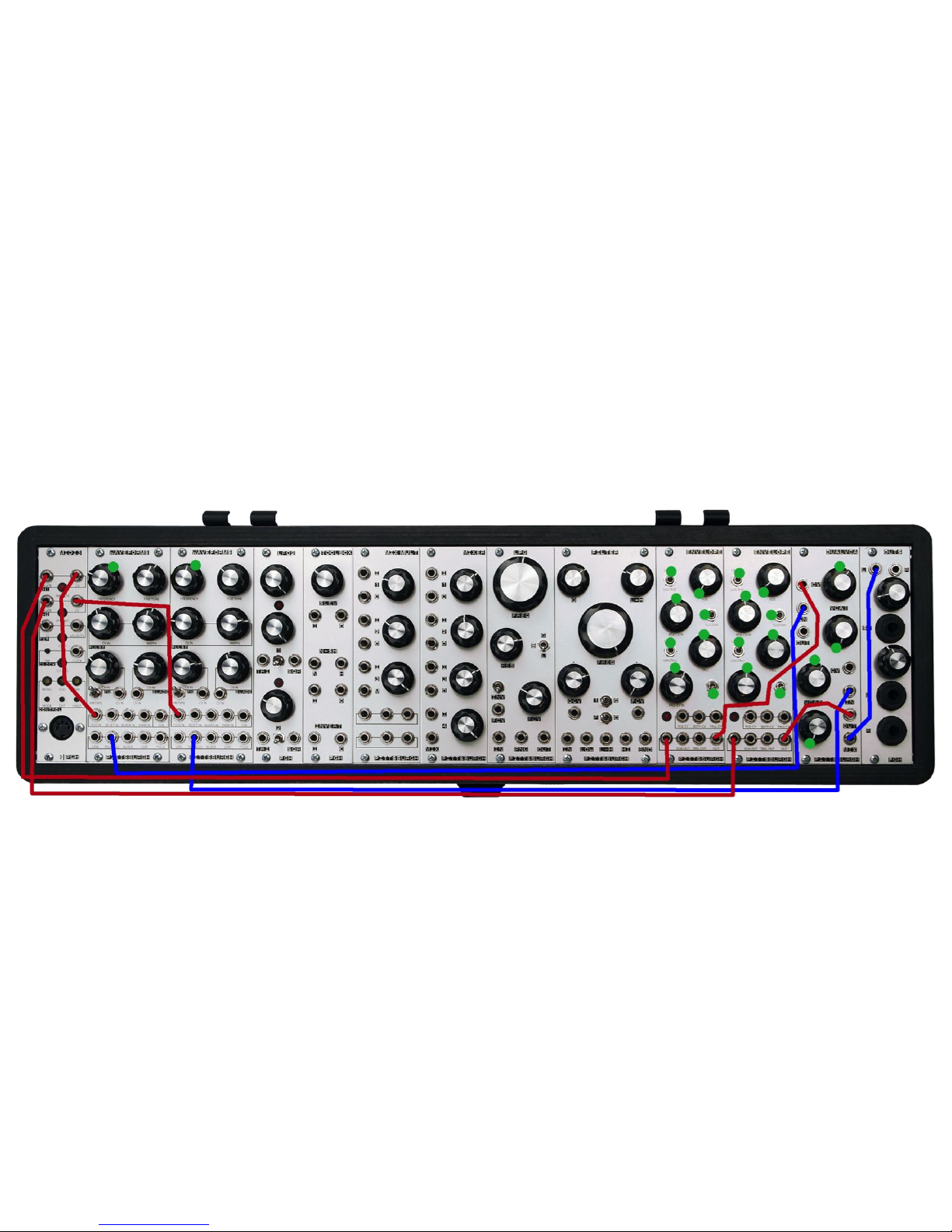
Midi 3 Test Patch
Description - Midi 3 Module Features Highlight
Notes - Audition the features of the Midi 3 module.!
24
Page 25
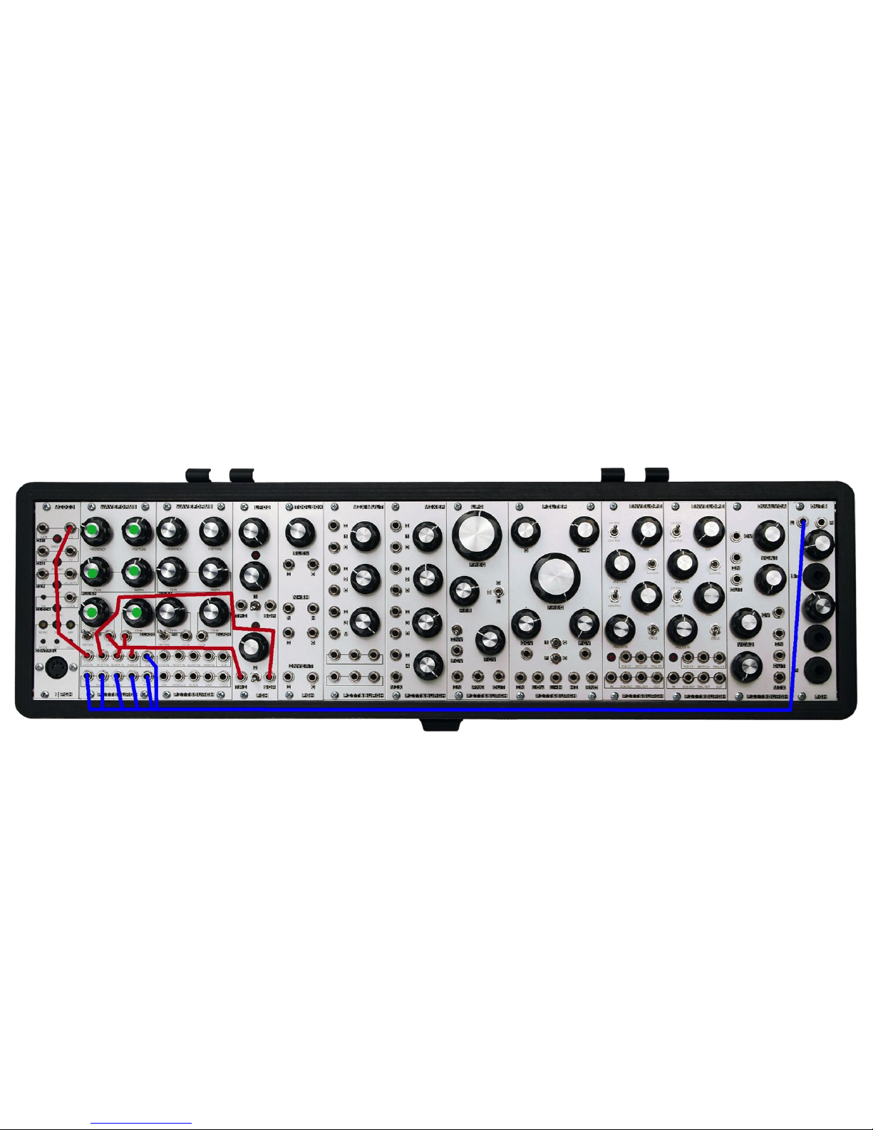
Waveforms Test Patch
Description - Waveforms Module Features Highlight
Notes - Audition each of the waveforms. The pulse wave is modulated using the Pulse section and PWM CV input. The blade wave is modulated using the
Blade CV IN section, Pulse section, PWM CV input, and the Blade Input. The sub oscillator is modulated and gated using the Pulse section and PWM CV
input.!
25
Page 26
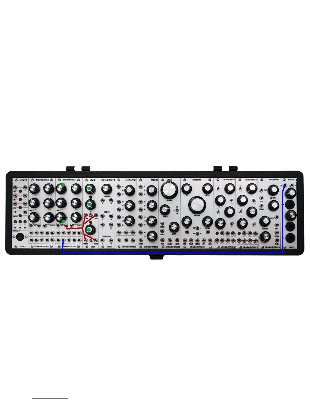
LFO2 Test Patch
Description - LFO2 Module Features Highlight
Notes - Audition the range and waveforms of the LFO2 module. Use the second knob from the top to adjust the waveform of LFO1. Use the switches to
control the range of each LFO.!
26
Page 27
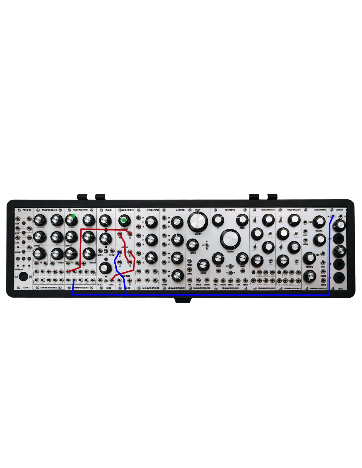
Toolbox Test Patch
Description - Toolbox Module Features Highlight
Notes - Audition each of the functions of the Toolbox. This patch creates the classic sample & hold random oscillator pitch. Patch the N (noise) output to
listen to the noise.!
27
Page 28
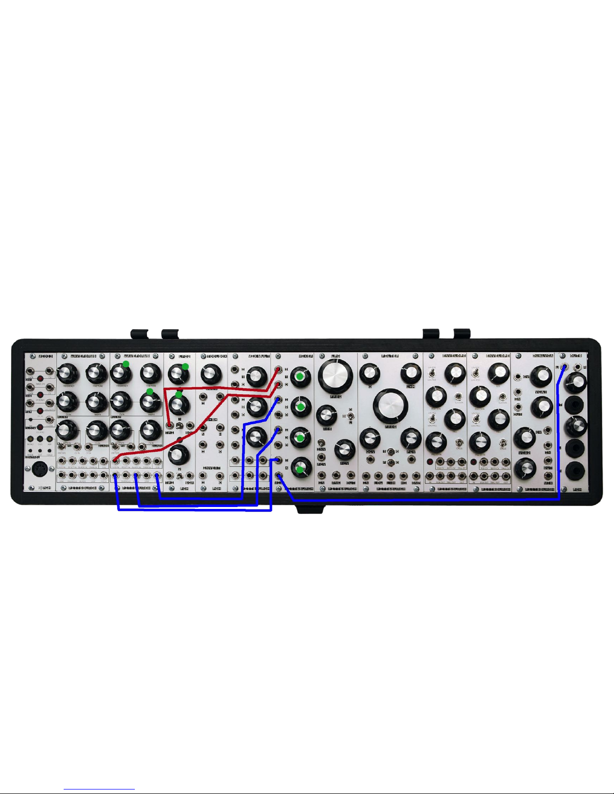
Mixer Test Patch
Description - Mixer Module Features Highlight
Notes - Audition the features of the Mixer module. Note the first channel is used as a passive attenuator in this patch therefore bypasses the mixer circuit.!
28
Page 29
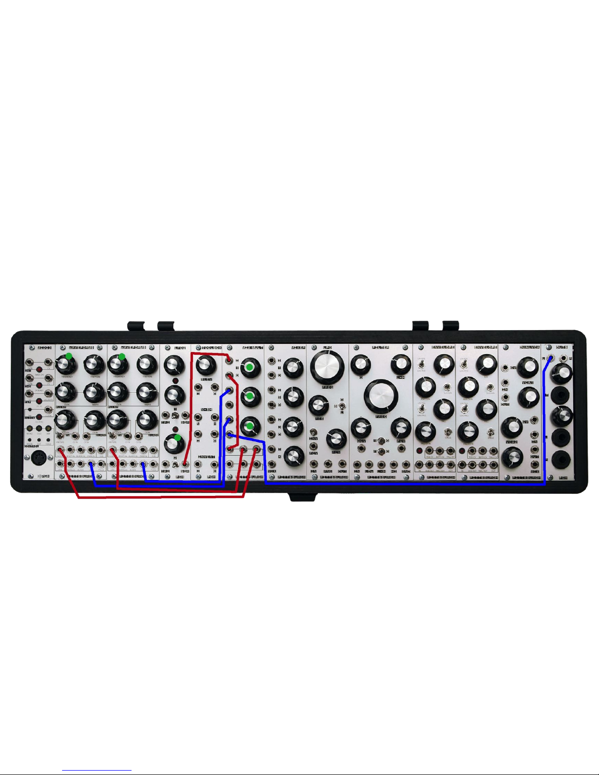
MixMult Test Patch
Description - MixMult Module Features Highlight
Notes - Audition the features of the MixMult module. Note the first channel is used as a passive attenuator and therefore bypasses the mixer circuit. The
multiple section is used to split an LFO square wave and send it to two separate destinations.!
29
Page 30
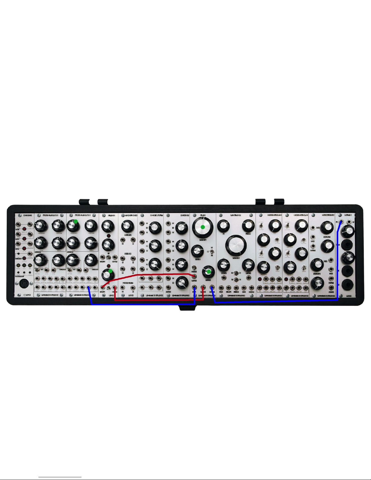
Lopass Gate Test Patch
Description - LPG Module Features Highlight
Notes - Audition the features of the LPG module. Test the FCV (frequency CV input) and PNG (ping gate input) separately. The RES (resonance) control works
only in L (low pass filter) mode. !
30
Page 31
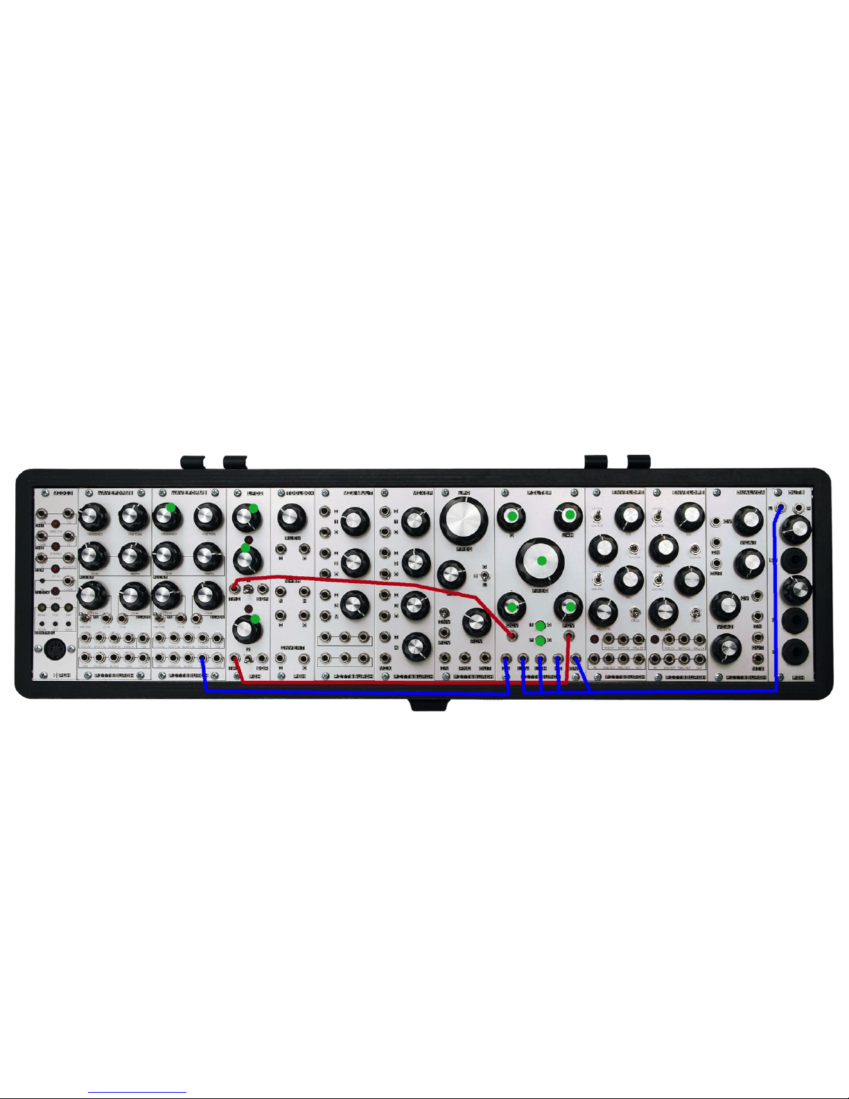
Filter Test Patch
Description - Filter Module Features Highlight
Notes - Audition the features of the Filter module. Test each of the outputs separately. The QCV (resonance CV) control and FCV (frequency CV) control are
attenuverters so left of 12 o’clock is inverting, 12 o’clock is off, and right of 12 o’clock is positive.!
31
Page 32
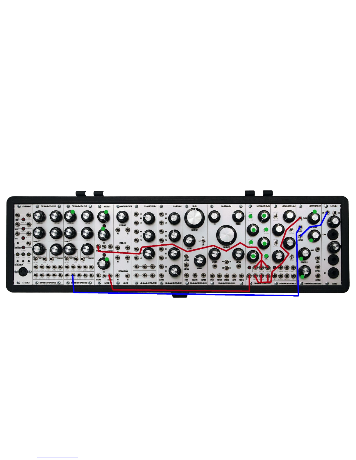
Envelope Test Patch
Description - Envelope Module Features Highlight
Notes - Audition the features of the Envelope module. Test each of the outputs separately. The Rise CV control and Fall CV control are attenuverters so left of
12 o’clock is inverting, 12 o’clock is off, and right of 12 o’clock is positive.!
32
Page 33
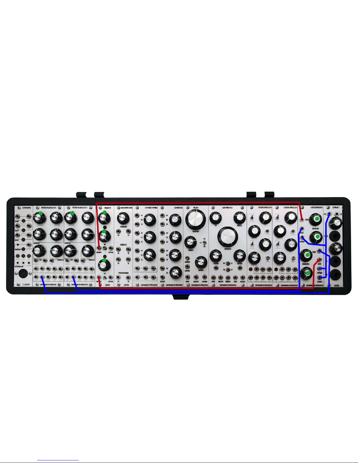
Dual VCA Test Patch
Description - Dual VCA Module Features Highlight
Notes - Audition the features of the Dual VCA module. Test each of the outputs separately. CV inputs and signal inputs are normaled so patching into the top
VCA routes the signal to the bottom VCA unless a patch cable is patched into the inputs of the bottom VCA.!
33
Page 34
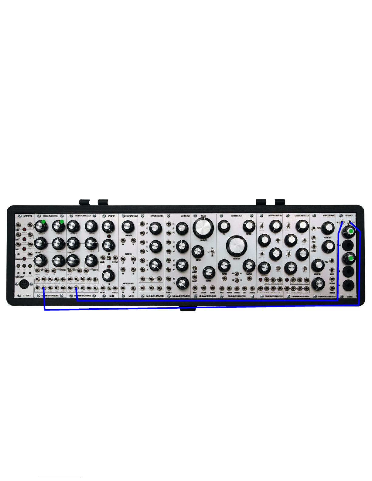
Outs Test Patch
Description - Outs Module Features Highlight
Notes - Audition the features of the Outs module. Test each of the outputs separately. Left and Right inputs are normaled so patching into the Left input
routes the signal to the Right input unless a patch cable is patched into the Right input of the Outs.!
34
Page 35
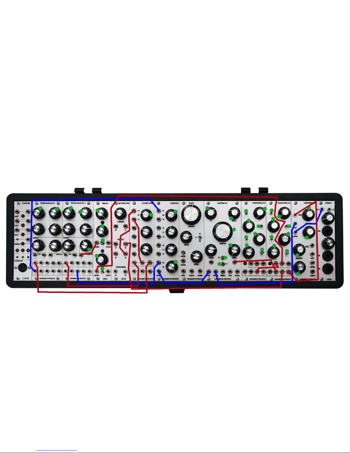
Bad Jazz Patch
Description - Bad Robot Jazz Guitarist Jamming With Itself
Notes - Self-generating patch in honor of noodlers everywhere.!
35
Page 36
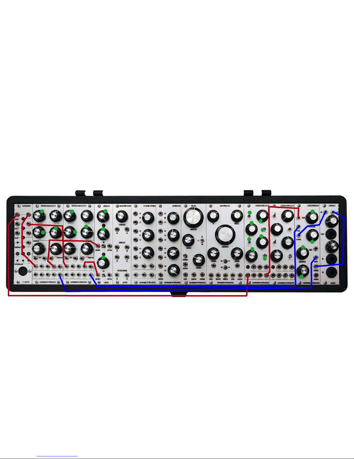
Stereo Synthesizer Patch
Description - Stereo Synthesizer With An Oscillator For Each Channel
Notes - Sending each oscillator to a separate output channel and controlling them with the same envelope.!
36
Page 37
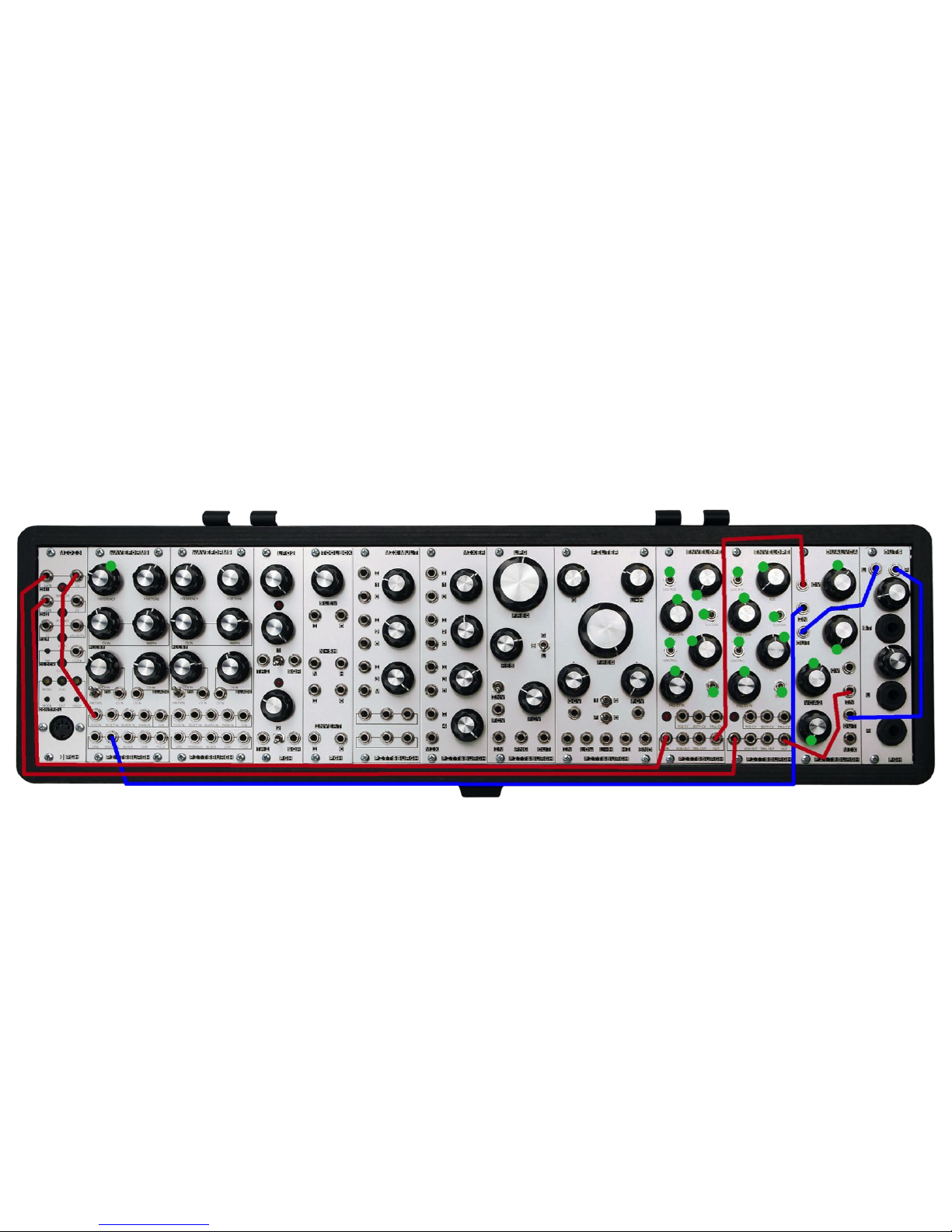
Panning VCA Patch
Description - A Single Oscillator Panning Left To Right
Notes - Using a single oscillator and 2 envelopes to pan a sound left to right.!
37
Page 38
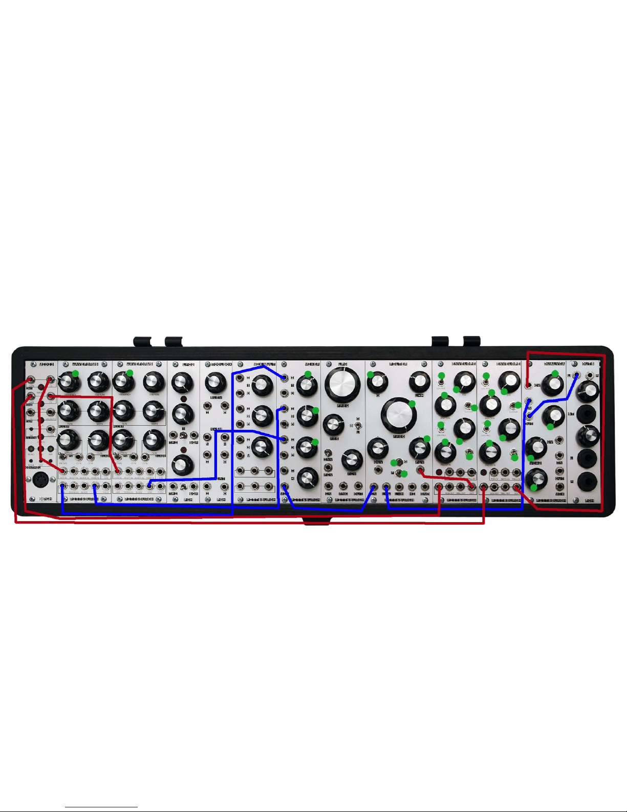
Filter Oscillator/Distortion Patch
Description - Example Of The Quirks And Noises Available From The Filter In Oscillator Mode
Notes - Adjust the Filter Q and Frequency to test the limits of the Filter in self-oscillation mode.!
38
Page 39
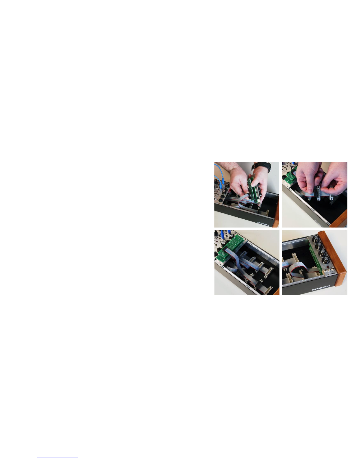
INSTALLING MODULES
Adding new modules to the case is a simple process. Please follow the instructions below to
ensure that new modules are installed safely and correctly.
Experiment with system layout by resting a few modules in the case before installation.
1. Switch the power off and unplug the power adapter from the back of the case.
2. The red stripe on the ribbon cable marks -12v. This stripe needs to line up with the -12v
pins on the module. Failure to match up the pins correctly can result in damage to one or
all the modules connected to the power supply.
3. Use a small tool to line up the needed sliding square nuts close to where the module will
be mounted.
4. Attach the module to the sliding nuts using the included panel screws. If installing more
than 1 module, do not tighten down the panel screws until all the modules are installed.
This will allow some room to shift the modules as needed.
5. Once all the new modules are installed, plug in the power adapter and switch on the case.
Carefully test each module to ensure it is working as expected.
39
Page 40
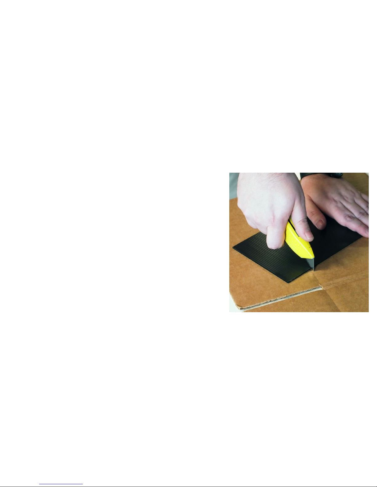
TRIMMING PLASTIC BLANK PANEL
The Plastic Blank Panel included with the Foundation 3.1+ is meant to be trimmed as modules
are added to the case. Use an X-ACTO or utility knife to cut the panel to fit around the added
modules. A ruler or straight edge can be used to ensure a clean line.
40
Page 41

Warranty
1 Year Limited Warranty:
For a period of one year after the date of original purchase, the instrument and all factory installed parts and modules manufactured by Pittsburgh Modular
Synthesizers LLC, are warranted to function properly and be free of defects in materials and workmanship. Should a factory installed module fail during the
warranty period, contact Pittsburgh Modular Synthesizers LLC. We will repair it (or at our option, replace it) at no charge, and pay the cost of shipping it back
to you.
The case and all case related hardware are warranted to function properly and be free of defects in materials and workmanship for 1 year.
Patch Cables are not covered by the 1 Year Limited Warranty.
This warranty is void if in our opinion the instrument has been damaged by accident, mishandled, altered, improperly serviced, or repaired by the customer
where such treatment has affected its performance or reliability. This includes but is not limited to damage related to incorrectly attaching power ribbon
cables. In the event of such misuse/abuse by the customer, costs for repairs plus two-way shipping costs will be borne by the customer. Instruments found
defective should be returned to the factory carefully packed, as the customer will be responsible for freight damage.
Incidental or consequential damages or costs incurred as a result of product malfunction are not the responsibility of Pittsburgh Modular Synthesizers LLC.
41
Page 42

Service and Contact Information
Please contact us for service or other information.
www.pittsburghmodular.com/contact
42
Page 43

Pittsburgh Modular Synthesizers
Copyright 2014 Pittsburgh Modular Synthesizers LLC
43
 Loading...