

Page 1
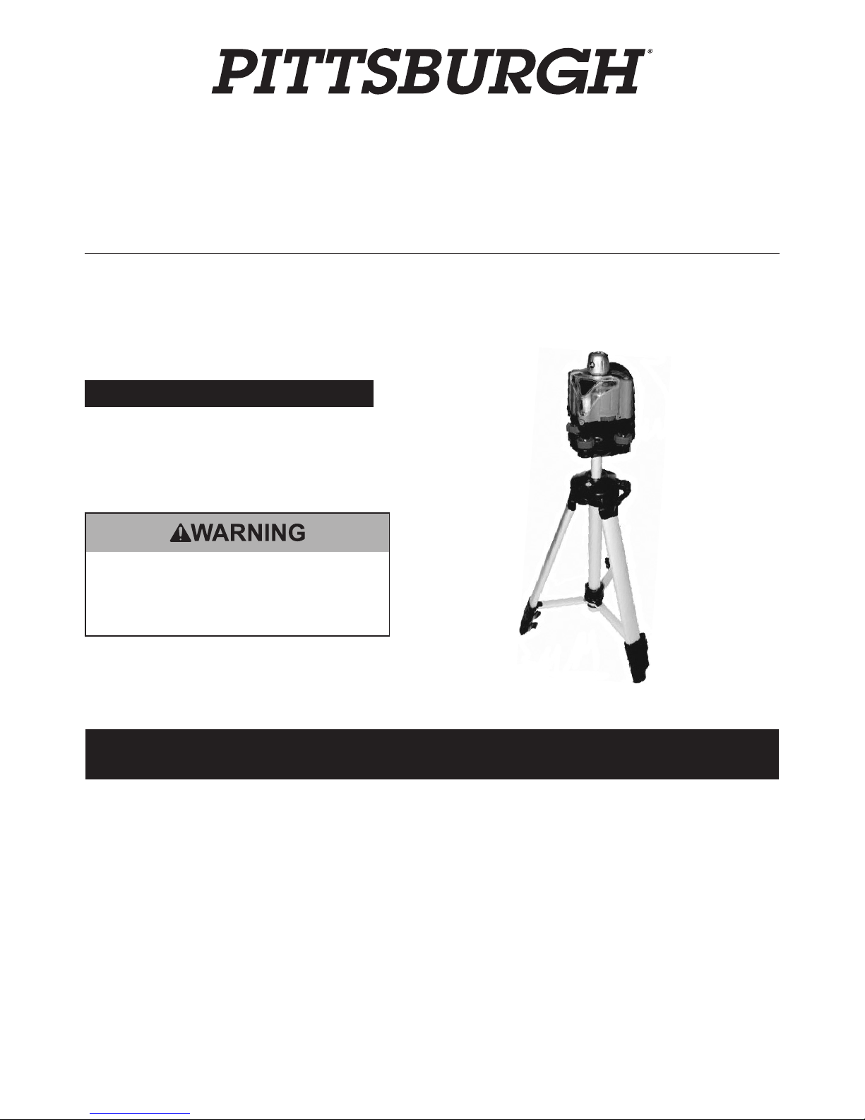
MOTORIZED ROTARY LASER LEVEL KIT
Item 92801
Read this material before using this product.
Failure to do so can result in serious injury.
SAVE THIS MANUAL.
When unpacking, make sure that the product is intact and undamaged.
If any parts are missing or broken, please call 1-800-444-3353 as soon as possible.
Visit our website at: http://www.harborfreight.com
Email our technical support at: [email protected]
Copyright© 2010 by Harbor Freight Tools®. All rights reserved. No portion of this manual or any artwork contained herein may be reproduced in any shape
or form without the express written consent of Harbor Freight Tools. Diagrams within this manual may not be drawn proportionally. Due to continuing
improvements, actual product may differ slightly from the product described herein. Tools required for assembly and service may not be included.
Manual Revised 11f
Page 2
Page 2 For technical questions, please call 1-800-444-3353. SKU 92801
Save This Manual
Keep this manual for the safety warnings and
precautions, assembly, operating, inspection,
maintenance and cleaning procedures. Write the
product’s serial number in the back of the manual near
the assembly diagram (or month and year of purchase
if product has no number). Keep this manual and the
receipt in a safe and dry place for future reference.
IMPORTANT SAFETY
INFORMATION
In this manual, on the labeling, and all other
information provided with this product:
This is the safety alert symbol. It is
used to alert you to potential personal
injury hazards. Obey all safety
messages that follow this symbol
to avoid possible injury or death.
DANGER indicates a hazardous situation which, if
not avoided, will result in death or serious injury.
WARNING indicates a hazardous situation which, if
not avoided, could result in death or serious injury.
CAUTION, used with the safety alert symbol,
indicates a hazardous situation which, if not
avoided, could result in minor or moderate injury.
NOTICE is used to address practices
not related to personal injury.
CAUTION, without the safety alert symbol, is used
to address practices not related to personal injury.
General Safety Warnings
WARNING! Read all safety warnings
and instructions. Save all warnings and
instructions for future reference.
1. Avoid direct eye exposure to laser light.
Do not direct the laser beam into the eyes of
any person or animal. Doing so may cause
severe eye injury or permanent blindness.
2. Verify Laser Level is in the “Off” position before
making any adjustments or changing the batteries.
3. Position batteries in proper polarity and
do not install batteries of different types,
charge levels, or capacities together.
4. Remove batteries if Laser Level is not to
be used for a long period of time.
5. The Laser Level is a delicate instrument;
do not drop or jar the Laser Level.
6. If installing on a wall surface without the Tripod (3),
verify that installation surface has no hidden
utility lines before drilling or driving screws.
7. Keep work area clean and well lit.
8. This product is not a toy.
Keep it out of reach of children.
9. Keep children and bystanders away
while operating Laser Level.
10. Inspect before every use;
do not use if parts are loose or damaged.
11. Stay alert, watch what you are doing and use
common sense when operating Laser Level.
Do not use Laser Level while you are tired or under
the inuence of drugs, alcohol or medication.
12. Dress properly. Do not wear loose clothing
or jewelry. Keep your hair, clothing and
gloves away from moving parts.
13. Maintain labels and nameplates on the tool.
These carry important safety information.
If unreadable or missing, contact Harbor
Freight Tools for a replacement.
14. WARNING: The brass components of this
product contain lead, a chemical known
to the State of California to cause birth
defects (or other reproductive harm).
(California Health & Safety code § 25249.5, et seq.)
15. The warnings, precautions, and instructions
discussed in this instruction manual cannot
cover all possible conditions and situations
that may occur. It must be understood by the
operator that common sense and caution are
factors which cannot be built into this product,
but must be supplied by the operator.
SAVE THESE
INSTRUCTIONS.
Page 3
Page 3For technical questions, please call 1-800-444-3353.SKU 92801
Specications
Laser Range Projects Up to 100′
Max. Tripod Height 48″
Rotation Capacity 360°
Batteries (4) ‘AA’ Batteries
Rotary Laser Level
ITEM 92801
05a-11c
Made in China.
LASER LIGHT
AVOID DIRECT EYE EXPOSURE
Max. Output: ≤ 5mW,
Wavelength: 650 nm ±10 nm
CLASS IIIa LASER PRODUCT
This product complies with
21 CFR 1040.10 and 1040.11
Diode Mfr.: Sean & Stephen Corp.
4F, NO3, Lane 335, Sec 4, Hsin-Yi Rd.,
Taipen, China
Manufacture Date: ___________, _______
Instructions for Putting Into Use
Read the ENTIRE IMPORTANT
SAFETY INFORMATION section at the
beginning of this manual including
all text under subheadings therein
before set up or use of this product.
TO PREVENT SERIOUS INJURY
FROM ACCIDENTAL OPERATION:
Turn the Power Switch to Off before adjusting Level.
Note: For additional information regarding
the parts listed in the following pages, refer to
the Assembly Diagram on the last page.
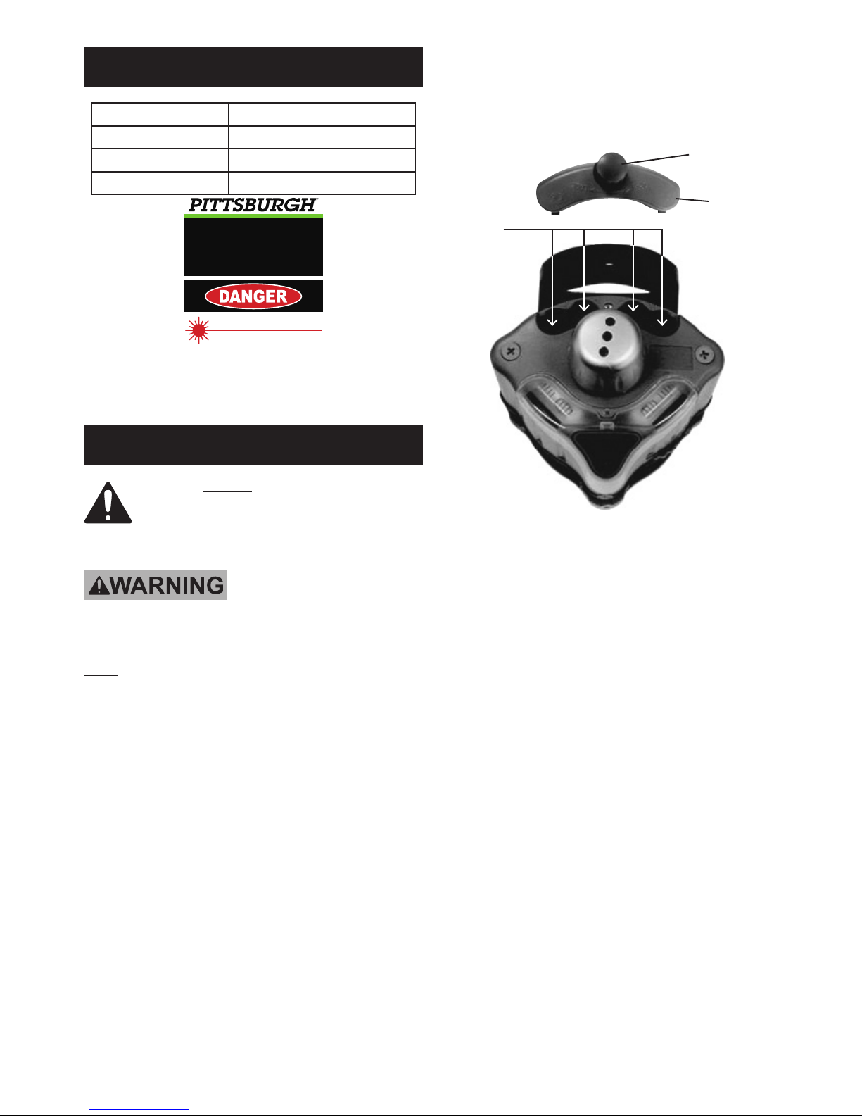
Installing The Batteries
1. Loosen the Battery Cover Knob (5A) and remove the
Battery Cover (2A). See Figure 1, below.
NOTE: The Knob will NOT come all the way out.
Battery
Cover (2A)insert
batteries
here
Battery Cover
Knob (5A)
Figure 1
2. Install four ‘AA’ Batteries, making sure to follow
the polarity marked in the Battery Compartment.
3. Replace the Battery Cover and turn Battery
Cover Knob until Cover is secured into place.
Page 4
Page 4 For technical questions, please call 1-800-444-3353. SKU 92801
Mounting To Tripod (3)
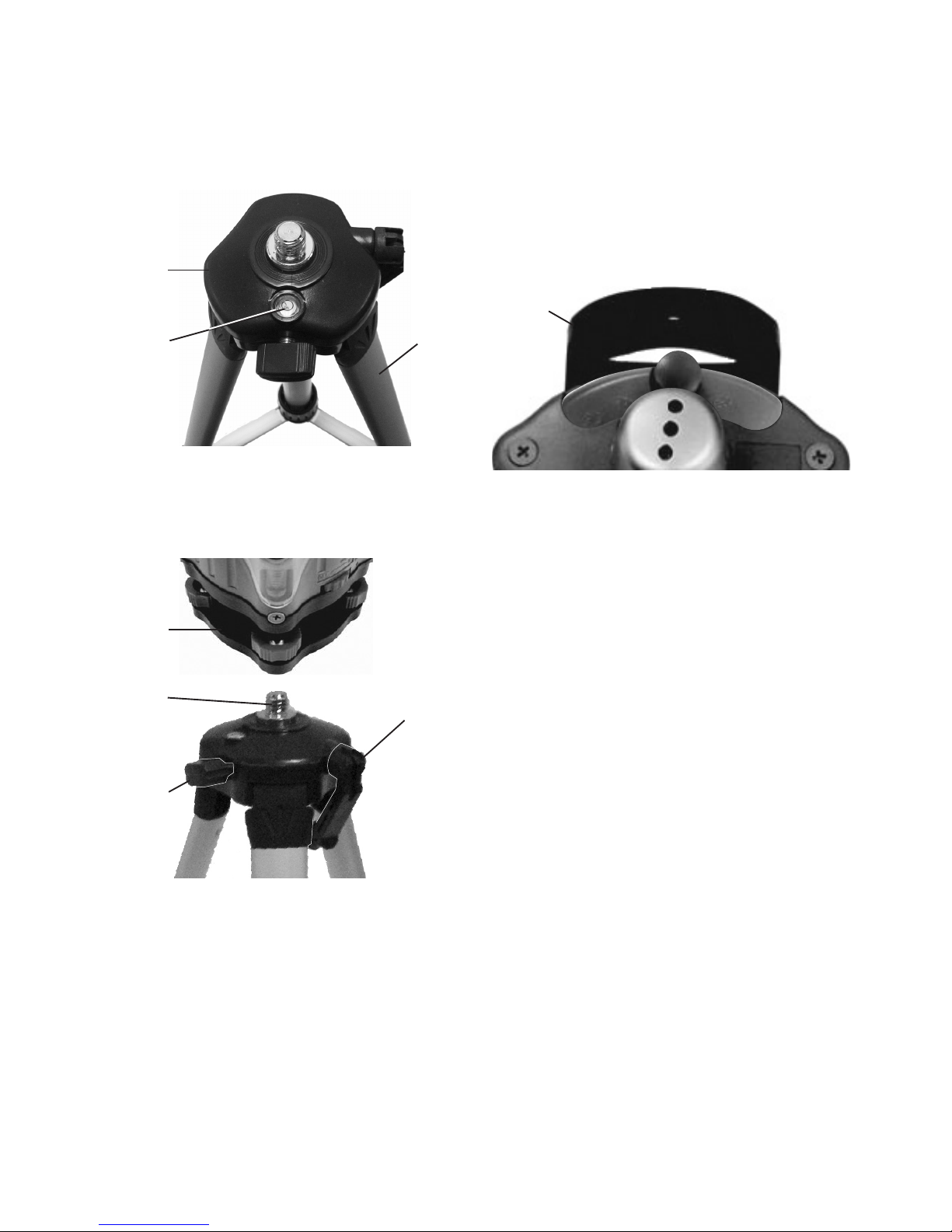
1. If mounting the Laser Level with the Tripod (3),
position the Tripod on a at and level ground surface.
Extend Tripod Legs to the desired height, using the
Bull’s Eye Vial (15) located on the Tripod Head (4).
See Figure 2, below.
Figure 2
Tripod
Head (4)
Bull’s Eye
Vial (15)
Tripod
(3)
2. Once the Tripod is level, lock the legs in
place using the clamps on each leg.
3. Then thread Wall Bracket (7A) onto
Tripod Head. See Figure 3, below.
Figure 3
Tripod
Head (4)
Wall
Bracket
(7A)
Height
Adjusting
Handle (13)
Height
Locking
Knob (14)
4. Once the Wall Bracket (7A) is secured on the head,
you can use the Height Adjusting Handle (13) to raise
the Level Housing to the desired height. Once the
desired height is reached, lock the height in place by
turning the Height Locking Knob (14). See Figure 3.
Mounting To Wall
1. The Laser Level may also be installed on a wall
surface without the Tripod. To do so, use the Wall
Bracket (7A) to secure the Laser Level to the wall.
2. First, set the Level Housing against the part of
the wall where you wish to install the Laser Level.
WARNING! Verify that installation surface has no
hidden utility lines before drilling or driving screws.
3. Use a pencil to mark drill holes through the
Wall Bracket (7A). See Figure 4, below.
Figure 4
Wall
Bracket
(7A)
4. Secure the Laser Level to the wall surface
using screws and plastic anchors (not included).
NOTE: The mounting screws must be long enough
to allow for the Wall Bracket frame to t over them.
5. Once installed on wall, level the Laser,
using the Leveling Knobs (8A) located
on each side of the Laser and the Level
Vials (9A) located at the top of the Laser.
Page 5

Page 5For technical questions, please call 1-800-444-3353.SKU 92801
Operating Instructions
Read the ENTIRE IMPORTANT
SAFETY INFORMATION section at the
beginning of this manual including
all text under subheadings therein
before set up or use of this product.
Initial Leveling
1. When the Laser Level is properly positioned,
activate the Laser by turning the Power /
Rotation Control Switch (11A), clockwise.
Then recheck the Level Vials (9A) to make sure
the Laser Level has not been bumped or moved.
2. The rotation speed of the Laser Head Cover (6A)
can be set by adjusting the Rotation Control Switch.
Turn clockwise to make the beam rotate faster.
Turn counterclockwise to slow the beam down.
3. Mark the desired measurement(s).
Then turn off the Laser Level by turning the Rotation
Control Switch counterclockwise all the way.
Equalizing Height Of
Distant Objects
1. For example, if you wish to install cement
footings for a storage shed, rst determine the
desired height of any one of the footings.
2. Align the laser beam with the top surface of the
reference footing, and check to make sure the
Vial Levels (9A) are level with the ground.
3. Direct laser beam toward each of remaining
footing locations. On reference stakes at those
locations, mark the spot the Laser illuminates.
This indicates desired top surface of that footing.
4. This technique can be used for many similar
applications, i.e., to align pictures on a wall.
Installing Horizontal Or
Vertical Objects
1. For example, to install a chair rail on an interior
wall, rst mark the desired height of the rail.
2. Align the Laser Level with that point, and check to
make sure the Vial Levels (9A) are level with the oor.
3. Shine laser beam on the adjoining wall, and
have an assistant mark that location.
4. Then, install the chair rail in a direct
line between the two points.
5. This technique can be used to install
vertical or 45 degree angle objects.
Checking a Slope
1. For example, to determine the slope of
a oor, place the Laser Level at one end
of the oor, using the Tripod (3).
2. Check to make sure the Vial Levels (9A) are level.
3. Measure the vertical drop from the
Laser Lens to the oor surface.
4. Shine the laser beam on a ruler held vertical at
the other end of the oor. The difference in these
measurements is the amount of slope in the oor.
5. This technique can be used to design slope,
such as when constructing an outdoor
surface which will require a runoff slope.
Page 6

Page 6 For technical questions, please call 1-800-444-3353. SKU 92801
Maintenance and Servicing
Proceduresnotspecicallyexplained
in this manual must be performed
onlybyaqualiedtechnician.
TO PREVENT SERIOUS INJURY
FROM ACCIDENTAL OPERATION:
Turn OFF the Laser Level before performing any
inspection, maintenance, or cleaning procedures.
TO PREVENT SERIOUS INJURY FROM TOOL
FAILURE: Do not use damaged equipment.
If abnormal noise or vibration occurs, have
the problem corrected before further use.
Cleaning, Maintenance,
and Lubrication
1. BEFORE EACH USE, inspect the general
condition of the Laser Level. Check for loose
hardware, misalignment or binding of moving
parts, cracked or broken parts, and any other
condition that may affect its safe operation.
2. AFTER USE, wipe external surfaces of
the tool with clean cloth. Do not immerse
the Laser Level in any liquids.
3. Store the Laser Level indoors and
out of children’s reach.
Page 7
Page 7For technical questions, please call 1-800-444-3353.SKU 92801
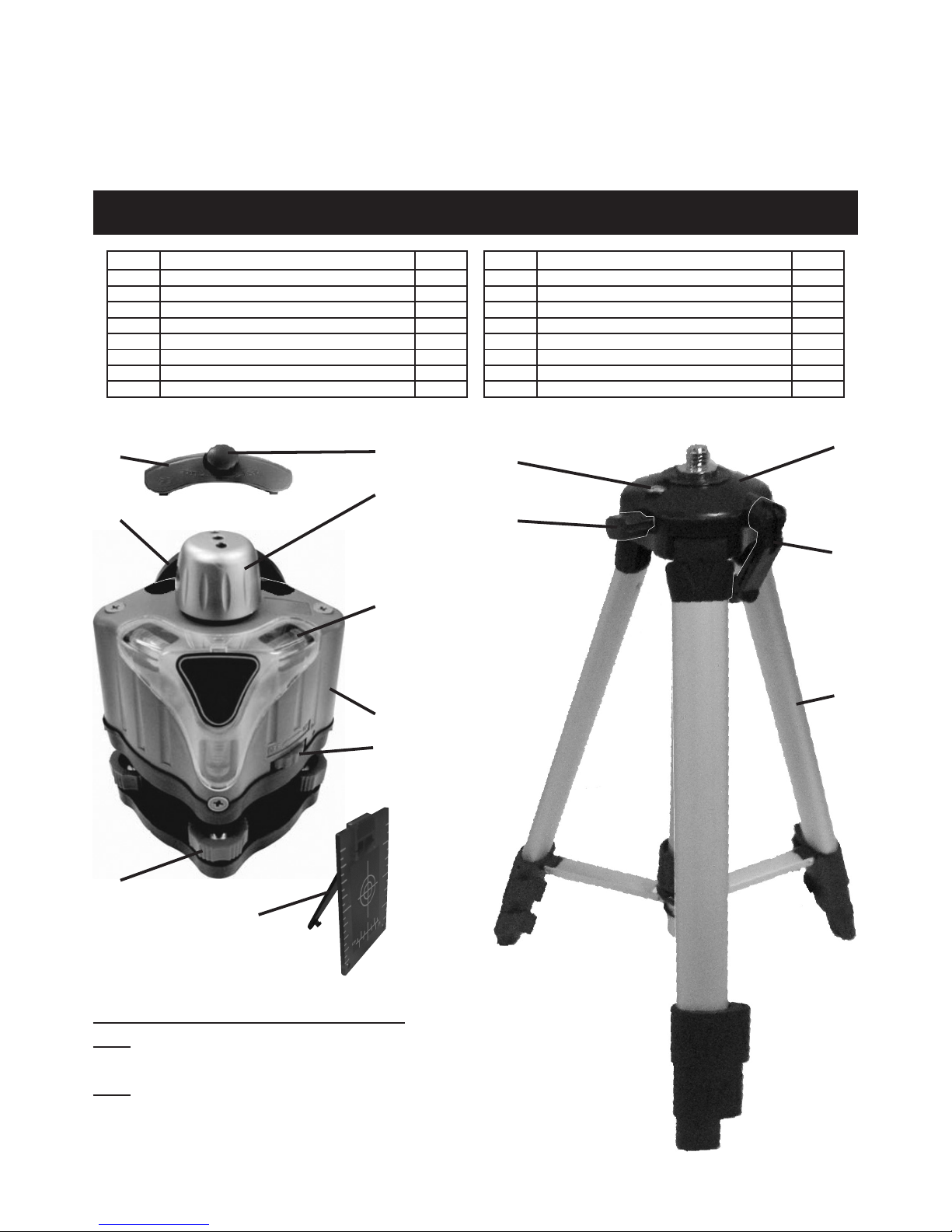
Part Description Qty.
1A ‘AA’ Battery (not included) 4
2A Battery Cover 1
3 Tripod 1
4 Tripod Head 1
5A Battery Cover Knob 1
6A Laser Head Cover 1
7A Wall Bracket 1
8A Leveling Knob 3
Part Description Qty.
9A Level Vial 3
10A Level Housing 1
11A Power / Rotation Control Switch 1
12 Glasses (not shown) 1
13 Height Adjusting Handle 1
14 Height Locking Knob 1
15 Bull’s Eye Vial 1
16 Target with stand and magnet 1
PLEASE READ THE FOLLOWING CAREFULLY
THE MANUFACTURER AND/OR DISTRIBUTOR HAS PROVIDED THE PARTS LIST AND ASSEMBLY DIAGRAM IN THIS MANUAL AS A
REFERENCE TOOL ONLY. NEITHER THE MANUFACTURER OR DISTRIBUTOR MAKES ANY REPRESENTATION OR WARRANTY OF ANY
KIND TO THE BUYER THAT HE OR SHE IS QUALIFIED TO MAKE ANY REPAIRS TO THE PRODUCT, OR THAT HE OR SHE IS QUALIFIED
TO REPLACE ANY PARTS OF THE PRODUCT. IN FACT, THE MANUFACTURER AND/OR DISTRIBUTOR EXPRESSLY STATES THAT
ALL REPAIRS AND PARTS REPLACEMENTS SHOULD BE UNDERTAKEN BY CERTIFIED AND LICENSED TECHNICIANS, AND NOT BY
THE BUYER. THE BUYER ASSUMES ALL RISK AND LIABILITY ARISING OUT OF HIS OR HER REPAIRS TO THE ORIGINAL PRODUCT
OR REPLACEMENT PARTS THERETO, OR ARISING OUT OF HIS OR HER INSTALLATION OF REPLACEMENT PARTS THERETO.
Parts List and Assembly Diagram
REV 11d
Record Product’s Serial Number Here:
Note: If product has no serial number,
record month and year of purchase instead.
Note: Some parts are listed and shown
for illustration purposes only, and are not
available individually as replacement parts.
Parts not shown to scale.
3
4
13
14
15
2A
5A
6A
7A
8A
9A
11A
10A
16
Page 8

LIMITED 90 DAY WARRANTY
Harbor Freight Tools Co. makes every effort to assure
that its products meet high quality and durability
standards, and warrants to the original purchaser
that this product is free from defects in materials and
workmanship for the period of 90 days from the date
of purchase. This warranty does not apply to damage
due directly or indirectly, to misuse, abuse, negligence
or accidents, repairs or alterations outside our facilities,
criminal activity, improper installation, normal wear and
tear, or to lack of maintenance. We shall in no event
be liable for death, injuries to persons or property, or
for incidental, contingent, special or consequential
damages arising from the use of our product. Some
states do not allow the exclusion or limitation of incidental
or consequential damages, so the above limitation of
exclusion may not apply to you. THIS WARRANTY IS
EXPRESSLY IN LIEU OF ALL OTHER WARRANTIES,
EXPRESS OR IMPLIED, INCLUDING THE
WARRANTIES OF MERCHANTABILITY AND FITNESS.
To take advantage of this warranty, the product or part
must be returned to us with transportation charges
prepaid. Proof of purchase date and an explanation
of the complaint must accompany the merchandise. If
our inspection veries the defect, we will either repair
or replace the product at our election or we may elect
to refund the purchase price if we cannot readily and
quickly provide you with a replacement. We will return
repaired products at our expense, but if we determine
there is no defect, or that the defect resulted from
causes not within the scope of our warranty, then
you must bear the cost of returning the product.
This warranty gives you specic legal rights and you may
also have other rights which vary from state to state.
3491 Mission Oaks Blvd. • PO Box 6009 • Camarillo, CA 93011 • (800) 444-3353
 Loading...