


Shockwave
Starter Package
User Guide
Shockwave Starter Package 33102 V1114 1
33102 V1114
Cautionary and Warning Statements
• This kit is designed and intended for educational purposes only.
• Use only under the direct supervision of an adult who has read and understood the instructions
provided in this user guide.
• Read warnings on packaging and in manual carefully.
• Always exercise caution when using sharp tools
• Do not mix old and new batteries.
• Do not mix alkaline, standard (carbon-zinc), or rechargeable (nickel-cadmium) batteries.
Introduction
The Shockwave Electric Dragster helps teachers get extra mileage out of their electronic CO2 race
systems featuring launch pods. It’s a fun activity that encourages students to look at electric cars as
an exciting option from the world of alternative energy.
This guide shows you how to put together and use all the parts of the Shockwave Starter Package.
The individual parts of the Shockwave will not work independently. For example, the Shockwave Car
Kit will not work without the Shockwave Module.
History of Electric Vehicles
While electric cars are in the spotlight today as an environment-friendly alternative to the gasolinepowered internal combustion engine, the concept has been around for more than 150 years. The
rst electric carriage – though crude – was built in the 1830s in Scotland by Robert Anderson. Some
credit Thomas Davenport as the rst, but his work was around the same time.
At the bridge between the nineteenth and twentieth centuries, electric cars actually outsold the
gas and steam versions – largely because they did not
require dicult shifting or a manual crank start nor
did they require passengers to smell gas fumes and
exhaust.
However, the improvement of the gasoline engine
and the roads, which allowed longer trips (electric was
good for short trips), and the reduced price of gasoline
combined to help gas-powered vehicles take the lead.
Between 1935 and 1960, the electric car was all but
forgotten.
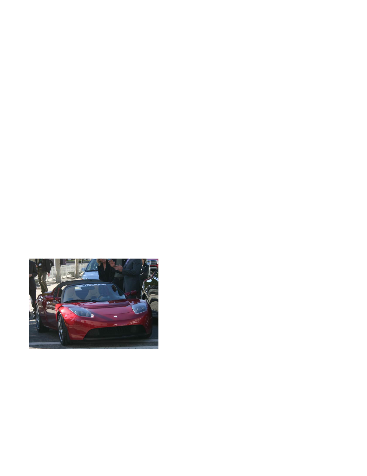
The Tesla Roadster is an electric car built
by Tesla Motors. The company is trying to
change the perception of electric cars. Photo
courtesy of Tesla Motors.
several manufacturers oered electric vehicles. Even the United States Post Oce tested out electric
jeeps.
During the 1960s and ‘70s, air pollution and
dependency on foreign oil companies prompted
engineers to take a fresh look at the electric car. Many
were developed over the next several decades, and
At the beginning of the twenty-rst century, the electric car still faced problems with production
and aordability. The organization Plug In America promotes the use of electric vehicles and lobbies
manufacturers to keep producing electric vehicles.
2 Shockwave Starter Package 33102 V1114

A popular alternative to the completely electric or gasoline car is the hybrid-electric vehicle, which
combines the two technologies to reduce fuel consumption.
Materials Included
Note: All materials except the Starting Blocks should be divided in half as these parts make up two
car kits.
• 2 sheets of laser-cut basswood parts
• 2 hooks
• 2 screw eyes
• 8 axle bushings
• 8 wheels
• 2 – 2-1/2" axles (front)
• 2 – 2-3/4" axles (rear)
• 2 gear fonts
• 2 motors with prewired connectors
• 2 motor mounts
• 4 screws
• 4 hex nuts
• 2 – 9 V batteries
• 2 Shockwave Modules
• 2 rubber bands
• Shockwave Starting Blocks, set of 2
Items Required (not included)
• White glue, such as Pitsco’s HD Bond II
• Small Phillips screwdriver
• Acrylic paint in color of choice (optional)
• Pitsco Wheel Deal (optional)
Note: The following instructions are for one car; there are enough materials in this package for two
cars.
• Hobby knife or sandpaper
• Tape, preferably double-stick (optional)
• Electronic CO2 race system with launch pods
Building the Car Body
1. Pop out the laser-cut parts from the basswood sheet. Find the
two Part 7s and Part 4. Glue one of the Part 7 pieces into a slot
on Part 4. Take the hook and insert one side of its T-shaped
end into the hole on the glued Part 7. Maneuver the other
side of the T end into the hole of the second Part 7. Glue that
Part 7 into the remaining slot on Part 4 (Figure 1). Let this
assembly dry.
2. Lay a Part 1 piece at on its side. In the rst slot on the
Figure 1
dragster’s front, glue Part 5. Moving toward the back of the
dragster one slot at a time, glue in one Part 2, the Part 3,
and then the second Part 2. Finally, glue in the
assembly from Step 1 so Part 4 is glued in the
dragster’s side with the pin on the underside of
the car (Figure 2).
3. Place glue on the other side of all the pieces
perpendicular to Part 1. Place the second Part 1
on top of these parts, tting the notches into the
side evenly and so the parts are all straight and t
snugly (Figure 2).
Shockwave Starter Package 33102 V1114 3
Figure 2

4. Take Part 8 and insert it through the
small notch below Part 3. This part
should extend a quarter inch from
either side of the dragster. Push it
slightly o center. Apply glue on Part
8 where it will touch the sides when
recentered (Figure 3). Recenter it.
5. Find Part 6 and glue it at on top of Part
5 so the small holes in both parts are
aligned. You could use a paper clip or a
piece of wire to hold the pieces in place
while they dry. Let the car dry.
6. If you wish to paint the dragster, do
Figure 3
that at this time. When any nishes on
the car are dry, turn the car upside down. Keeping the screw eye
straight, screw it into the small hole on the underside of Part 5.
Make sure the hole on the screw eye is facing the front and back
of the dragster (not the sides).
Adding the Wheels, Gears, and Motor
1. In the axle holes, push in the axle
bushings; the wide edge of the
bus hings should be on the outside
of the car body (Figure 4).
2. Push one wheel on the end of a
front axle (a 2-1/2" axle). Slide the
other end through the front axle
bushings. Carefully, place a second
wheel on the free end of the axle.
(If available, use the Wheel Deal to
push the wheels onto the axle.) Be
sure the wheels aren’t on so tight
that they cannot spin.
3. Remove from the gear font the
40T gear with a 1/8" axle hole.
Using a hobby knife or sandpaper,
remove any burrs from the gear.
This is the drive gear. Push the gear
onto the end of the rear axle so
3/8" of the axle extends from one
side of the gear.
Figure 4
Figure 4 - Top View
4. Place a wheel on the short end of
the axle. Push the other end through the back bushings on the
car’s left side – the left side if you were looking at the car from
behind (Figure 4). Place a fourth wheel on that end.
4 Shockwave Starter Package 33102 V1114
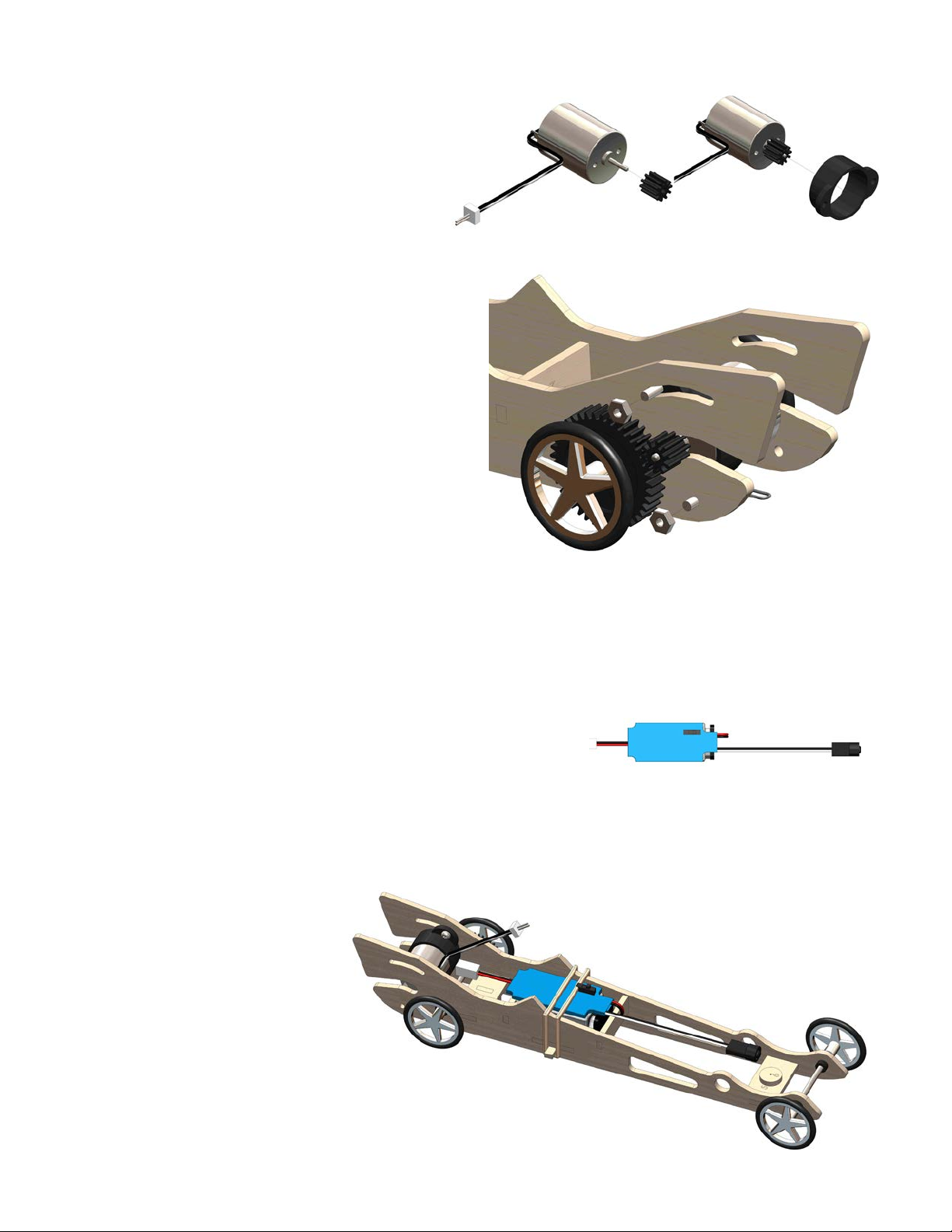
5. Remove from the gear font the pinion
gear, which is the smallest gear with a
2 mm hole. Place this on the end of the
motor post (Figure 5).
6. Slide the motor mount over the motor
post and onto the motor; the sides of
the motor and motor mount should be
ush (Figure 6). Place the motor into
the slot on the back of the dragster
with the motor post facing the drive gear.
With one screw and hex nut, attach one
side of the motor mount to the hole below
the motor slot.
7. Maneuver the top of the motor until the
pinion gear meshes into the drive gear
about halfway. Make sure the gears spin
freely and – without moving the gears
– use the second screw and hex nut to
secure the top of the motor mount in
place (Figure 7).
Figure 5
Figure 7
Figure 6
Attaching the Module
1. Make sure the module is turned o; it is o when the switch
is facing away from the battery connector (Figure 8).
2. Connect the module to the battery. Fold the assembly so
the battery is under the module with the switch facing up.
Place this into the center area of the dragster between the
Part 2 pieces (Figure 9). Make sure the motor connector is
hanging free behind the module and battery (toward the
motor). The wire with the infrared (IR) detector also hangs
free but in front of the module.
3. Take the rubber band and hook one end over the end of
Part 8. Stretch the rubber band over the module and hook
the other end on the other side of Part 8 (Figure 9).
4. Connect the motor to the
module (Figure 9). This only
ts one way; if it doesn’t go
in, turn it and try again.
Figure 8
Figure 9
Shockwave Starter Package 33102 V1114 5

5. At this time, determine in which lane your
dragster will race. If you are using the Impulse
GII or Impulse race systems, determine what
side of your dragster will be near the middle of
the track (see Figure 10a). Place the IR detector
so it ts in the hole facing the middle of the
track.
If you are using the i-race or Palm Racer
systems, determine what side of your dragster
will be facing the outside of the track (see
Figure 10b). Place the IR detector so it ts in the
hole facing the outside of the track.
Tip: To make sure everything is set up properly
before putting the dragster on a track, test it with
a 60-watt incandescent light. Simply turn the
module switch to the on position (toward the
Figure 10a
motor connector), and hold the IR detector under the light. The motor should turn on. When it does,
set the car on the oor and it should move forward (be sure someone is ready to pick up the car
before it runs into anything). Hold the detector under the light again and the motor will turn o.
If the car moves backward, the motor post and gears are probably placed on the wrong (right) side
of the Shockwave.
Placing the Starting Blocks and Running the Race
Note: You can use either manual or auto mode when racing the Shockwave.
1. Set up your race system as usual except do not attach the launch pods. In the ports for the launch
pods, plug in the starting blocks instead.
2. For the Impulse GII or Impulse race systems,
place the starting blocks in the center of the
track at the starting line (Figure 10a). The IR
emitters (the small bulb inset on one side of
each starting block) should face away from
the center of the track. You might need to
tape them down to the track to make them
stay in place.
For the i-race or Palm Racer systems, place
the starting blocks on the outside edges of
the track – one on each side (Figure 10b).
The IR emitters should face toward the
center of the track. You might need to tape
them down to the track to make them stay
in place.
Figure 10b
6 Shockwave Starter Package 33102 V1114
3. Attach the dragsters to the racetrack with monolament line as usual, and then line up the IR
detectors on the cars to the IR emitters on the starting blocks. Without moving the dragsters, turn
on the module.
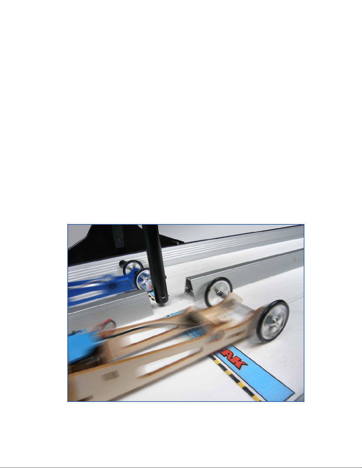
4. Run the race as normal. When the dragster passes the nish gate, the motor will turn o
automatically. Then, switch o the module and remove the dragster (Figure 11).
Tip: If you have to rerun the same cars and don’t want to remove them from the track’s
monolament line, be sure to turn o the module before rolling them back up the track. If the
module is on and the dragster passes the IR emitter while rolling back, it will turn on automatically.
Activity Ideas
• The gear font in this package features several dierent sizes of gears. Have students study gear
ratios.* Then, have them design dierent gear combinations for the Shockwave and hypothesize
how it will perform with each combination. Students can test each combination on the track,
record the times of each race, and learn if their hypotheses were correct.
• With standard CO2 dragsters, weight is an important variable. Have students think of ways they
can alter the weight of the Shockwave (adding a load, carefully shaving down the wooden body,
and so forth). Race the cars to see the result of the weight changes.
*One way to learn about gear ratios is by experimenting with the Pitsco Gear Factor (32242).
Figure 11
Shockwave Starter Package 33102 V1114 7

P.O. Box 1708 • Pittsburg, KS 66762
www.pitsco.com
Toll-Free Orders 800-835-0686
 Loading...