

Page 1
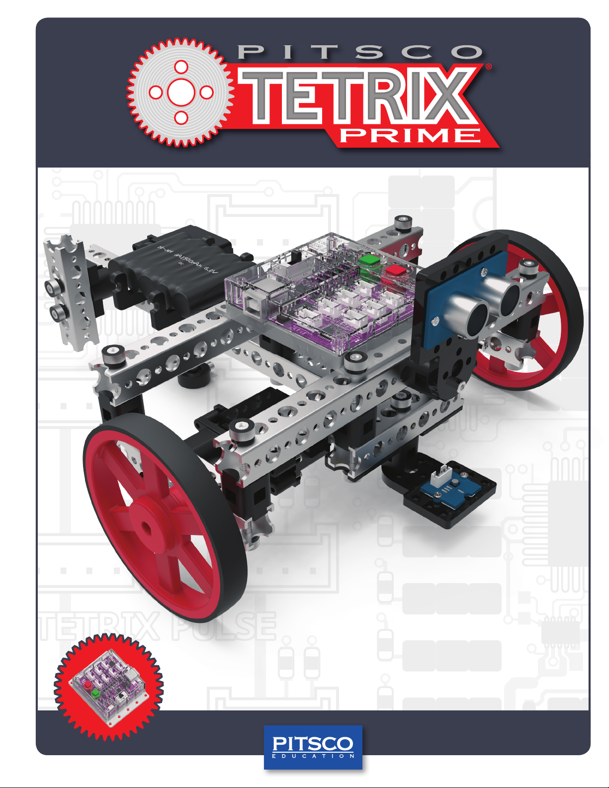
TETRIX® PULSE™ Robotics Controller
Programming Guide
44301
Page 2

Content advising by Tammy Pankey, Paul Uttley, and Tim Lankford.
Build creation and SolidWorks® Composer™ and KeyShot® renderings by Tim Lankford, Brian Eckelberry, and Jason Redd.
Desktop publishing by Todd McGeorge.
©2017 Pitsco, Inc., 915 E. Jefferson, Pittsburg, KS 66762
All rights reserved. This product and related documentation are protected by copyright and are distributed under licenses
restricting their use, copying, and distribution. No part of this product or related documentation may be reproduced in any
form by any means without prior written authorization of Pitsco, Inc.
All other product names mentioned herein might be the trademarks of their respective owners.
Check TETRIXrobotics.com for PDF updates of this guide.
V1.0
8/17
Page 3

Table of Contents
Preface ......................................................................................................................................................................................................................2
TETRIX® PULSE™ Robotics Controller Introduction ................................................................................. 3
PULSE Controller Technology Overview .............................................................................................................. 4-6
PULSE Setup ................................................................................................................................................................................................. 7-8
Software Overview ................................................................................................................................................................................. 9
Software Setup ....................................................................................................................................................................................10-23
Getting Started Activities ........................................................................................................................................................... 24
Activity 1: Hello World! ....................................................................................................................................................................25-28
Activity 2: Moving Your DC Motors............................................................................................................................................ 29-32
Activity 3: Moving Your Servo Motors ...................................................................................................................................... 33-36
Activity 4: Introduction to the Line Finder Sensor .............................................................................................................. 37-40
Activity 5: Introduction to the Ultrasonic Sensor ................................................................................................................ 41-44
Building and Coding the PULSE Codee Bot .......................................................................................................45
Hardware Overview ......................................................................................................................................................................... 46-68
Activity 6: Build the PULSE Codee Bot ..................................................................................................................................... 69-87
Activity 7: Drive Forward ................................................................................................................................................................ 88-91
Activity 8: Drive in a Circle ............................................................................................................................................................. 92-94
Activity 9: Drive in a Square .......................................................................................................................................................... 95-99
Activity 10: Simplify the Square ............................................................................................................................................. 100-103
Activity 11: Drive to a Line and Stop .................................................................................................................................... 104-107
Activity 12: Follow a Line .......................................................................................................................................................... 108-111
Activity 13: Drive Toward a Wall and Stop ......................................................................................................................... 112-115
Activity 14: Avoiding Obstacles ............................................................................................................................................. 116-118
Activity 15: Combining the Sensors ..................................................................................................................................... 119-122
Build, Code, Test, Learn . . . Go! ........................................................................................................................................................ 123
Appendix
Scope and Sequence ........................................................................................................................................................................... 124
Standards Addressed .......................................................................................................................................................................... 125
Glossary ............................................................................................................................................................................................ 126-127
Getting Started Extension Activities .................................................................................................................................... 128-129
Careers Complete Listing ................................................................................................................................................................... 130
TETRIX PULSE Robotics Controller Technical Specifications ............................................................................................... 131
TETRIX PULSE Controller Sensor Port Pinout Diagrams ...............................................................................................132-133
TETRIX PULSE Arduino Library Functions Chart ............................................................................................................. 134-140
TETRIX PULSE Arduino Library Functions Cheat Sheet ......................................................................................................... 141
Notes .......................................................................................................................................................................................................... 142
Page 4

Preface
This programming guide has been developed to provide students with positive experiences in robotics engineering and
programming. With the assistance of this guide, students will learn to use the TETRIX® PRIME parts to construct different
robots while learning about programming with the PULSE controller. After using this guide, students should be able to use
the TETRIX PRIME parts to construct a robot of their own design.
Grade Level Appropriateness
The activities used in this guide are targeted toward middle school students. With some additional instruction, upperelementary students should be able to successfully complete the activities. Additionally, secondary teachers could use
these parts to provide an exploratory experience in engineering.
Using This Guide
The activities in this guide build upon each other. The activities should be completed in the order in which they are
presented. Concepts explored in one activity might not be repeated in later activities, but students could be required to
understand the concepts in order to be most successful.
Safety Information
Mechanical
• Keep fingers, hair, and loose articles of clothing clear of gears and moving parts.
• Never pick up the robot while it is moving or the servo motors are running.
Electrical
• Make sure the power is turned off when the robot is not in operation.
• Do not operate the robot in a wet environment.
• Always power down the robot before making any changes.
• Use caution when working with bare wires to avoid creating a short circuit situation.
• Route wires carefully, and secure them if necessary to avoid damage to the wire or its insulation.
• Mount the battery pack securely.
2 Getting Started
Page 5
Welcome to Coding with PULSE™
and Building with TETRIX PRIME!
PULSE Controller Introduction
Pitsco Education is pleased to bring you the TETRIX® PULSE™ Robotics Controller Programming Guide – an exciting and
progressive series of activities that teaches the essentials of learning to program your TETRIX PRIME creations using the
PULSE controller and the graphic-based TETRIX Ardublockly software.
This programming guide offers a valuable tool for teaching students and teachers how to use the PULSE controller (the
brain) and the TETRIX PRIME system to build and code smart, precise robots that are as real world as it gets. The guide
comes with five getting started activities, step-by-step building instructions for creating a Codee Bot, 10 complete Codee
Bot-oriented lessons, and extension activities. This is a great tool for exploring the functionality of the PULSE controller,
TETRIX hardware components, and software. Your students are offered a great foundation to build on.
By combining the plug-and-play PULSE controller with the intuitive PRIME building system and an easy-to-use, graphicbased software environment, this solution offers a great entry into teaching and learning through robotics. The progressive
nature of the activities enables robotic creations to come to life quickly and easily, meaning students can experience instant
success and focus more classroom time on problem solving and applying their STEM knowledge.
Plus, PULSE is not just a great tool for teaching programming. It can bring to life lessons on sensors, power, gear ratios, and
more. Even the controller’s clear polycarbonate shield was designed to maximize educational value – letting users see the
inner architecture of the controller.
We have also included some STEM connections (concepts beyond the scope of this guide) that can be covered in each
lesson if you choose to do so. These connections can be incorporated if you have content knowledge of these concepts or if
you can work with other teachers to integrate these concepts.
We hope this guide offers a great jumping-off point to learning with PULSE. We cannot wait to see the innovative projects
and robotic creations that result.
My name is Codee!
I’ll follow your every
command.
Getting Started 3
Page 6
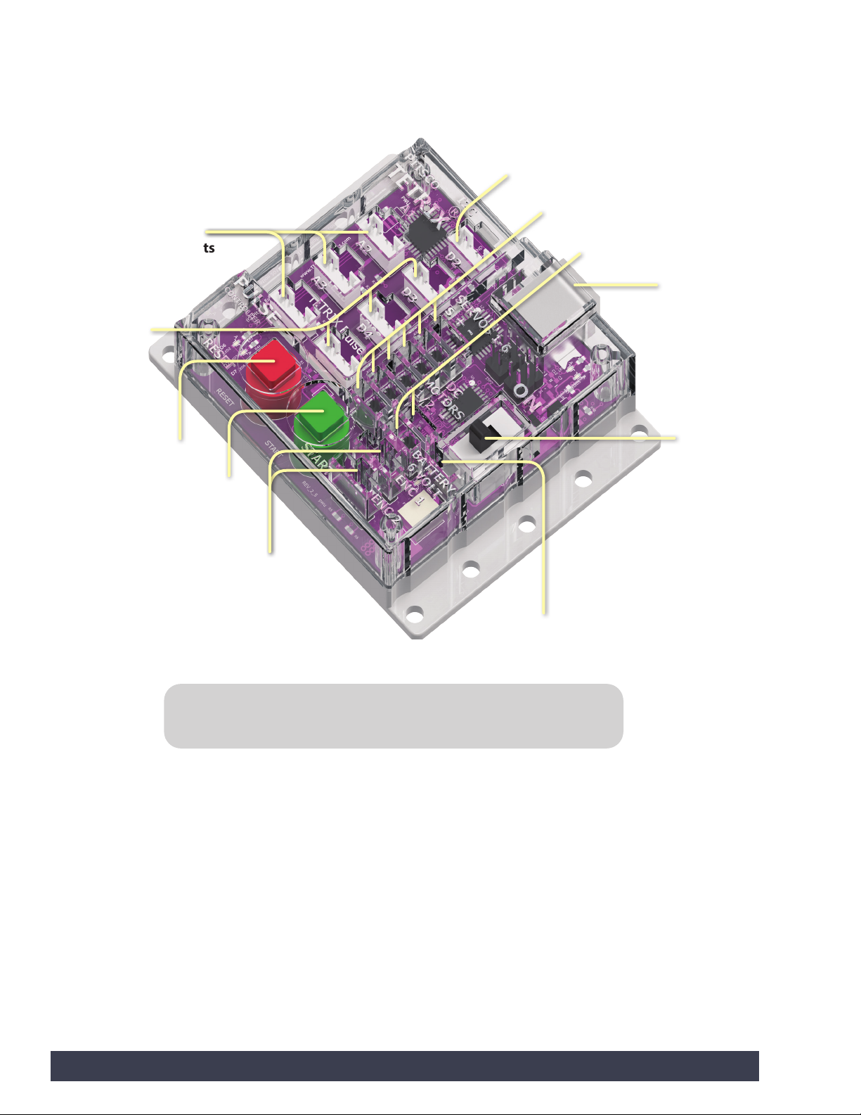
PULSE Controller Technology Overview
PULSE Robotics Controller:
A programmable device that is the brain of the TETRIX PRIME robot
3 analog
sensor ports
3 digital
sensor ports
Stop/Reset
button
Start
button
i2C port
6 standard control servo ports
2 DC motor control ports
USB
programming
port
Power
switch
2 quadrature
encoder input ports
Battery connection port
Tip: For complete, detailed specifications, please refer to the TETRIX PULSE
Robotics Controller Specifications located in the appendix on page 131.
4 Getting Started
Page 7
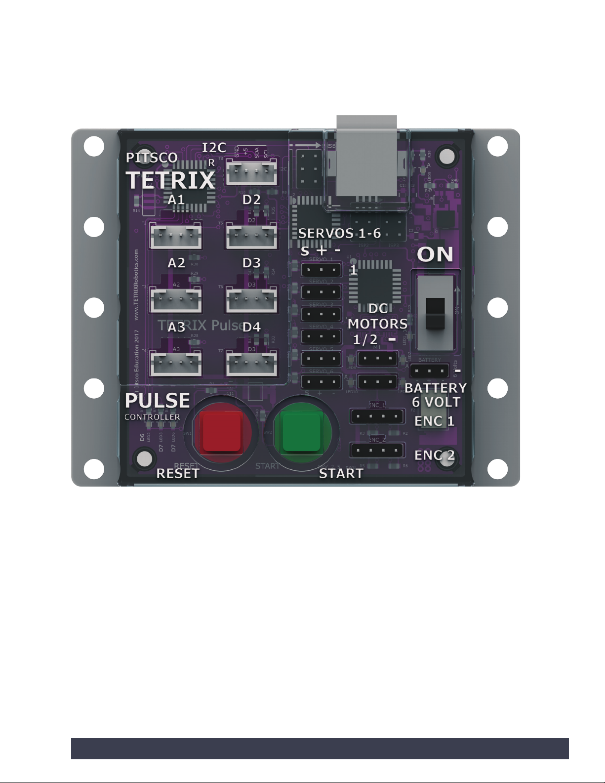
PULSE Controller Technology Overview
Getting Started 5
Page 8
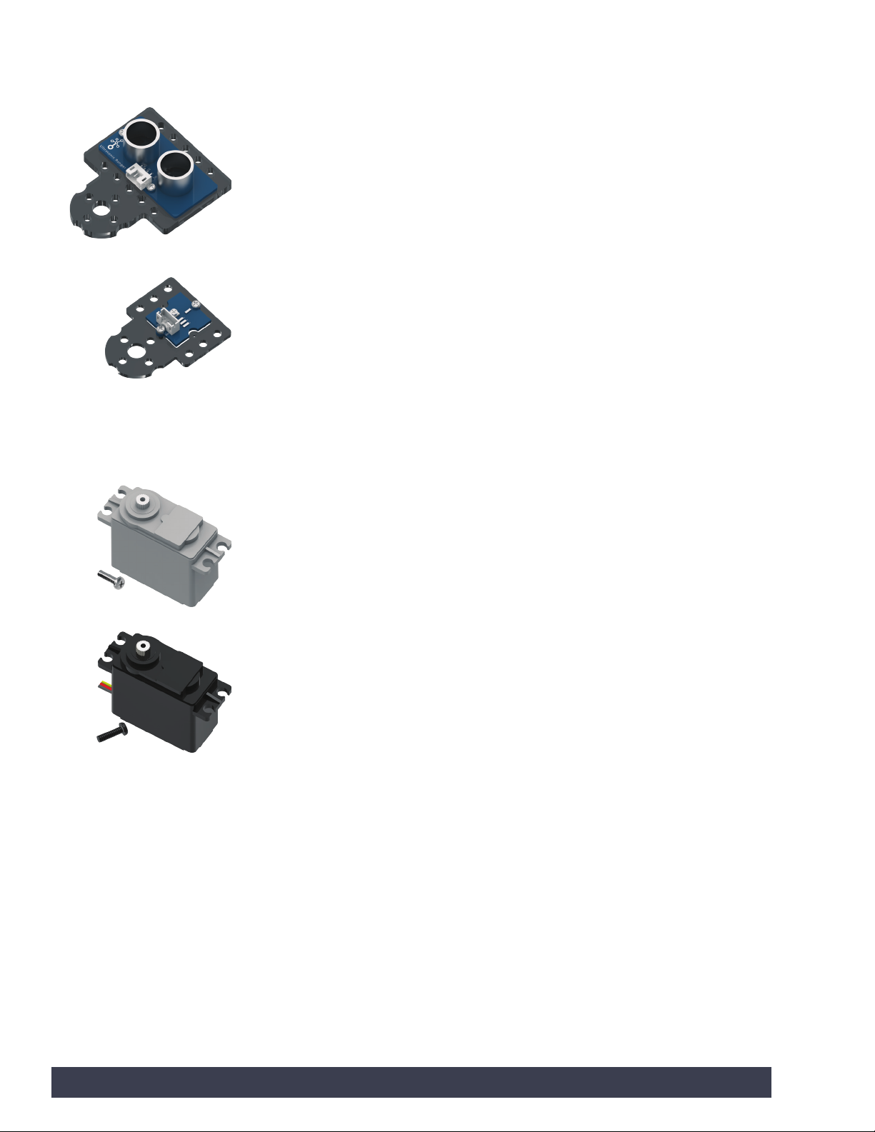
Sensor:
A device that detects surrounding environmental factors for the controller
Ultrasonic Sensor:
Enables a robot to measure
distance to an object and
respond to movement
Line Finder Sensor:
Enables a robot to follow
a black line on a white
background or vice versa
Motor:
A machine that produces motion or power for completing work
DC Motor:
Allows for speed and
torque
Standard Servo Motor:
Allows for exact
positioning within a
180-degree range of
motion
6 Getting Started
Page 9
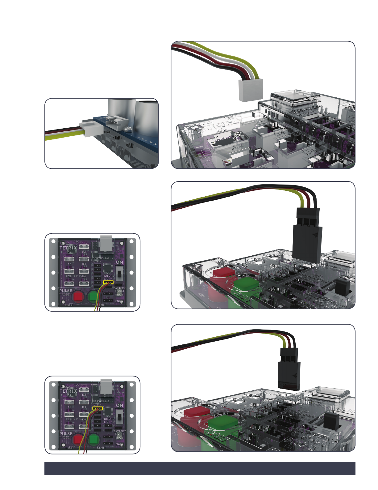
PULSE Setup
Attaching the Sensors:
To connect a sensor to the PULSE, plug the
end of the sensor wire into ports labeled
D2-D4 for digital sensors, A1-A3 for analog
sensors, or I2C for I2C components.
Attaching the DC Motors:
To connect a DC motor to the PULSE, plug
the end of the DC motor wire into one of
the two DC motor ports.
Important: The black wire end must be
closest to the minus sign on the controller.
Attaching the Servo Motors:
To connect a standard servo motor to the
PULSE, plug the end of the servo motor wire
into one of the servo ports
Important: The black wire end must be
closest to the minus sign on the controller.
Getting Started 7
Page 10
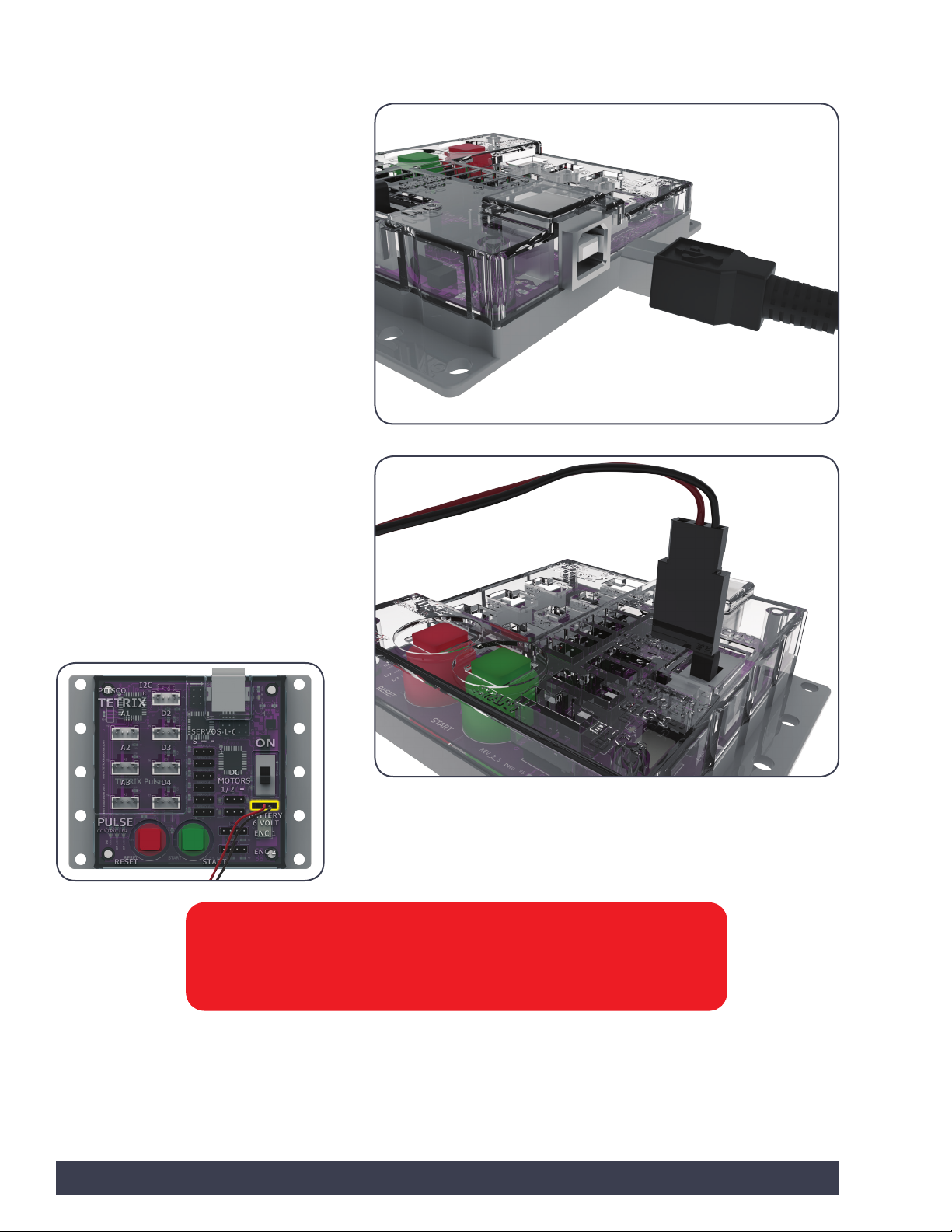
Downloading and Uploading:
The PULSE USB port is used for
communication between PULSE and a
Windows or Macintosh device.
The port enables users to download and
upload data from the computer to the PULSE
controller.
To upload a program to the PULSE, plug one
end of the USB cable into the controller’s USB
port and plug the other end into a USB port
on your device.
Attaching the Battery to the PULSE:
The PULSE controller is powered by a
TETRIX 6-Volt Rechargeable NiMH Battery
Pack.
To connect the battery pack to the PULSE,
plug the end of the battery wire into the
battery port located on the controller.
Important: The black wire end must be
closest to the minus sign on the controller.
Warning: Do not attempt to use third-party battery packs with the PULSE
controller. The TETRIX battery packs are equipped with a safety fuse and are
the only packs approved for use with the system. Damage to the product as a
result of doing so will void your warranty.
8 Getting Started
Page 11

Software Overview
• The TETRIX Ardublockly software is a special programming interface created
by Pitsco for exclusive use with the PULSE controller. The TETRIX Ardublockly
software was developed using the Google interface called Blockly.
• It can be used on a variety of Windows and Macintosh devices. The software
is placed on the hard drive of a device. The device used must have a USB
port for connection to the PULSE controller. It is not supported on tablets or
Chromebooks.
• The Arduino Software (IDE) will be used to communicate with the PULSE in the
background. You don’t need to open the Arduino Software (IDE) to create your
programs. It only needs to be installed on the computer. The PULSE controller
can be programmed through the Arduino Software (IDE), but for this guide, all
programming will occur within the TETRIX Ardublockly software.
• Within the TETRIX Ardublockly software, a program is referred to as a sketch.
Each of the activities in this guide will involve creating a sketch that gives
instructions to the robot.
• For the purposes of this guide, we will focus on the basics of using the
TETRIX Ardublockly software as it applies to the PULSE controller. Working
through examples and hands-on application of code using a small Codee Bot
constructed with the TETRIX PRIME robotics building system will show you
how easy it is to use TETRIX Ardublockly with PULSE.
Note: This is not meant to be
a tutorial on programming
with the Arduino C-based
language. There are
many excellent resources
available on the web to
learn more about advanced
programming skills. If you are
interested in such resources,
a good place to start would
be the Arduino website at
www.arduino.cc.
Getting Started 9
Page 12
Arduino Software (IDE) Setup
The first thing we need to do is install the Arduino Software (IDE). The software can
be found at the Arduino website (www.arduino.cc) for Windows and Macintosh
operating systems. From the Arduino homepage, click the Software tab. On the
Software page, select the download for your operating system and follow any
additional instructions.
Installing the PULSE Controller Library
Adding custom libraries can expand the usability of the Arduino Software (IDE).
Libraries are collections of code that make it easier to create a program, or, as
Arduino calls it, a sketch. After you have successfully installed the Arduino Software
(IDE), you must add the Arduino PULSE controller library. The PULSE controller
library contains special programs written for the TETRIX PULSE controller.
The PULSE library is distributed as a .zip file: TETRIX_PULSE.zip. The first step is to
download the PULSE library from the TETRIX website. We can find the library at
www.TETRIXrobotics.com/PULSEdownloads.
After the library has been downloaded, there are two ways to install the PULSE
library into the Arduino Software (IDE).
Importing a .zip Library
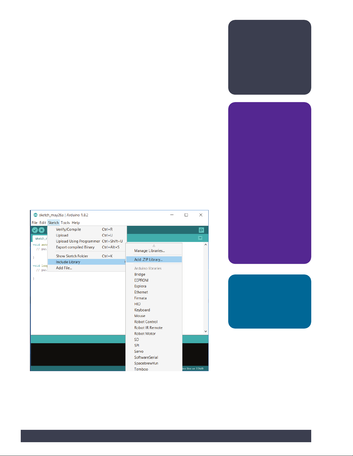
One way is to import it using the Arduino Software (IDE) Add .ZIP Library menu
option.
In the Arduino Software (IDE), navigate to Sketch > Include Library. From the dropdown menu, select Add .ZIP Library (Figure 1).
Note: All instructions
and screen shots used
throughout this guide are
based on the 1.8.2 version of
the Arduino Software (IDE).
Instructions and views might
slightly vary based on the
platform and version you are
using.
Teacher note:
• Depending on your
classroom and IT situation,
you might want to
download and install the
Arduino Software (IDE) and
the TETRIX PULSE Arduino
Library on the computers
you and your students will
be using.
• It is recommended that
you organize the class
into teams of two. It is
recommended that you
go through each process
before students do. This
will enable you to have a
good understanding of
what student questions
might arise and how to
answer those questions.
10 Getting Started
Tip: Figures within this
section show typical
installation within Windows.
The look and file locations
within the Mac operating
system might vary.
Figure 1
Page 13
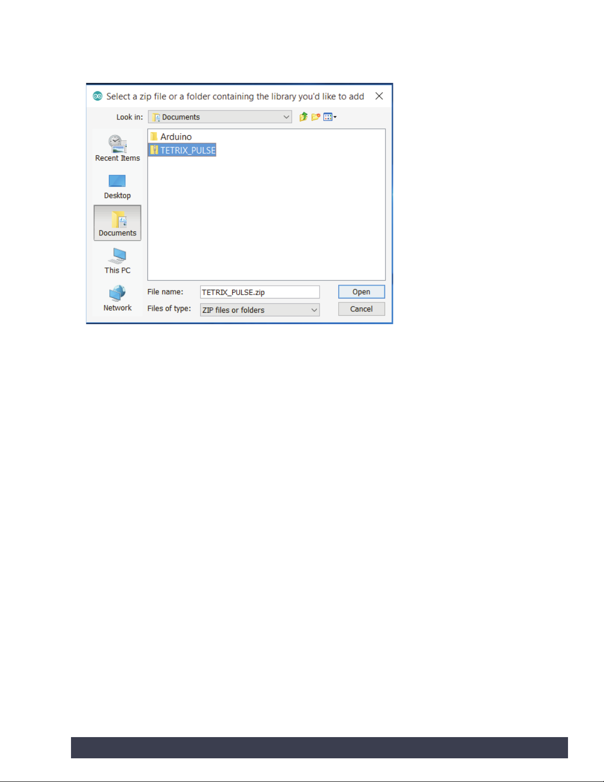
You will be prompted to select the library you would like to add. Navigate to the
location where you saved the TETRIX_PULSE.zip library file, select it, and open it
(Figure 2).
Figure 2
Return to the Sketch > Include Library menu. You should now see the library at
the bottom of the drop-down menu. It is ready to be used in our sketches; however,
example sketches for the library will not appear in the File > Examples menu until
after the Arduino Software (IDE) has been restarted.
Manual Installation
To install the PULSE library manually, first close the Arduino Software (IDE)
application. Then, extract the .zip file TETRIX_PULSE.zip containing the library. After
the folder is extracted, drag or copy the TETRIX_PULSE folder into the Arduino
libraries folder.
For Windows users, it will likely be called Documents\Arduino\libraries.
For Mac users, it will likely be called Documents/Arduino/libraries.
Restart the Arduino Software (IDE). Make sure the TETRIX_PULSE library appears in
the Sketch > Include Library menu of the software.
In addition, several PULSE sketch examples will now appear in the File >
Examples > TETRIX_PULSE drop-down menu.
That’s it! We have successfully installed the PULSE Arduino library.
Getting Started 11
Page 14
Configuring USB Communication
PULSE and the Arduino Software (IDE) will communicate with each other through
the computer’s USB port.
Therefore, before we can begin programming, we first need to be sure that the
PULSE controller is properly set up in the Arduino Software (IDE) for communication
over the USB port.
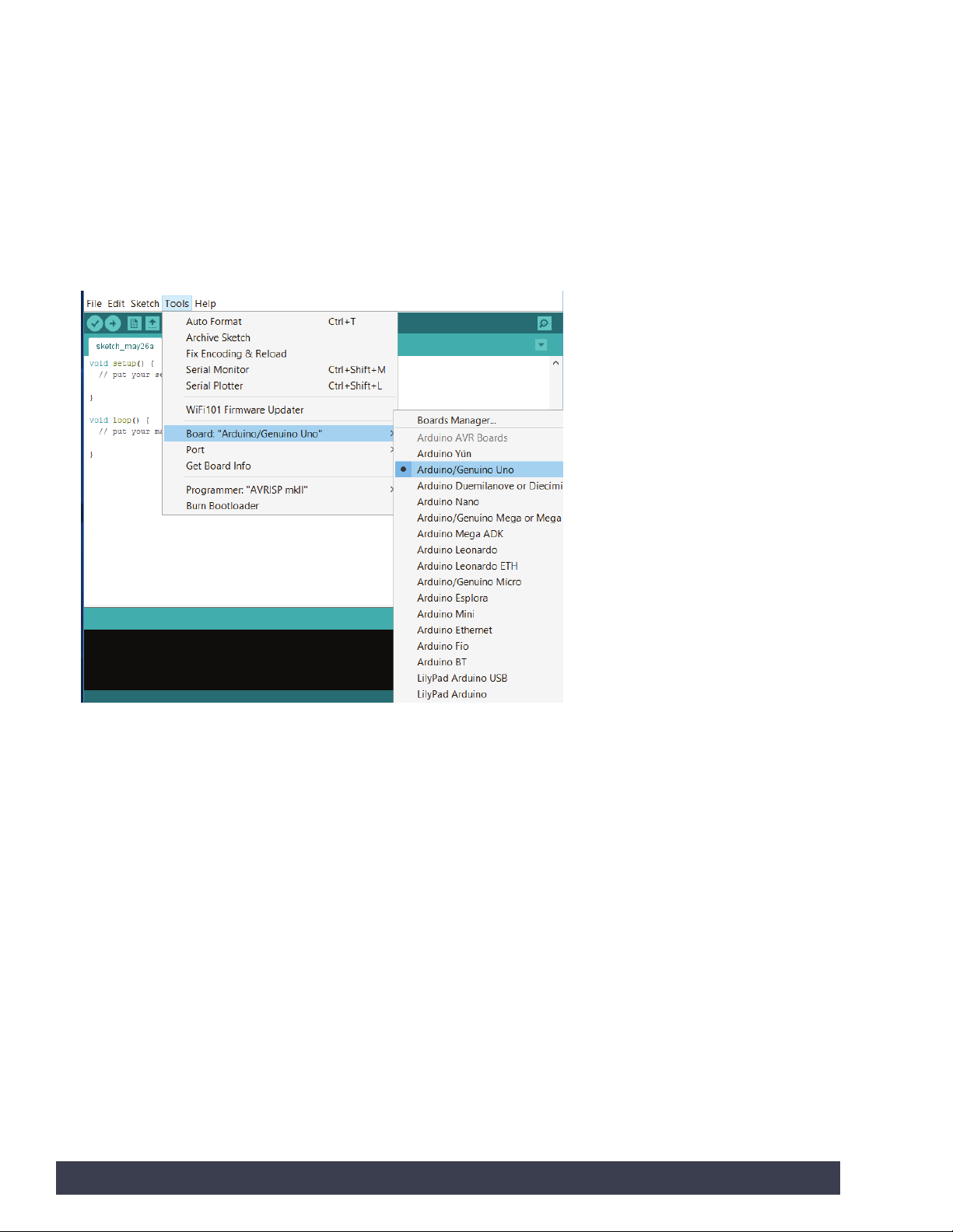
The easiest way to do this is to first start the Arduino Software (IDE) and navigate to
Tools > Board and select Arduino/Genuino Uno (Figure 3). The PULSE controller
uses the same processor chip as a genuine Arduino UNO, so this is the board you
will select.
Figure 3
12 Getting Started
Page 15
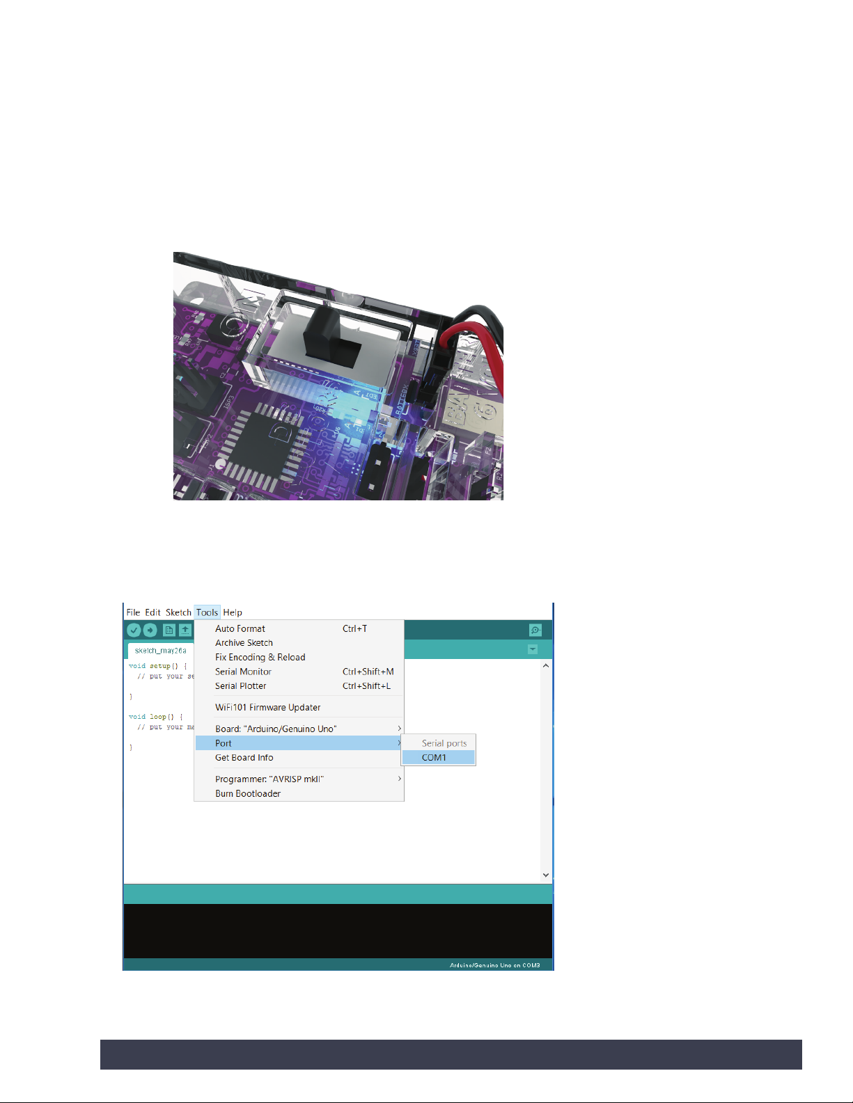
Next, without the PULSE connected, navigate to Tools > Port and check the
current connections. If there are no current connections detected, the word Port will
be grayed out. If there are connections detected, take note of the COM ports that
are listed.
Next, plug the PULSE controller into a USB port and power it up by connecting the
TETRIX battery pack and turning the power switch on.
With power applied, the blue power indicator LED will be lit. Be sure to give the
PULSE controller time to complete the first-time connect installation. This could
take 5-10 seconds. After the PULSE has been connected and installed, it will be
assigned a COM port by the computer system.
Navigate to Tools > Port and select the newly installed COM port. The new COM
port will be the PULSE. By selecting the new COM port, you are telling the Arduino
Software (IDE) to use this port for communications. The COM port you use could be
different from the one in Figure 4.
Figure 4: Port drop-down menu with PULSE not connected.
Please note that lists might vary.
Getting Started 13
Page 16

The new port that appears in this example is COM1. Select the new port item to
tell the Arduino Software (IDE) to use this port for communications. Your port will
likely be different, and that is OK. When the communications port has been set up,
communications with the PULSE controller have been enabled.
When this step is complete, our computer system will automatically default to
this selected port each time we plug in our PULSE controller and start the Arduino
Software (IDE).
Tip: Each PULSE unit will
use a different COM port
on the same computer.
For each new PULSE that
is connected, follow the
steps for numbering
controllers and matching
to the computer as detailed
above. You can number
each PULSE controller and
assign it to a corresponding
computer. This will facilitate
the computer selecting the
correct port for PULSE each
time it is connected and
powered up.
Note: Other devices
connected to the computer,
such as a cell phone, might
show up as a COM port
as well. You might have to
go back into the Arduino
Software (IDE) if you have
another device connected at
the same time to ensure the
right COM port is selected.
14 Getting Started
Page 17
TETRIX Ardublockly Software Setup
The TETRIX Ardublockly software is distributed as a .zip file: TETRIX_Ardublockly.
zip. There is a version for the Windows operating system and a version for the Mac
operating system. The first step is to download the appropriate version for your
device from the TETRIX website. You can find the library at www.TETRIXrobotics.
com/PULSEdownloads.
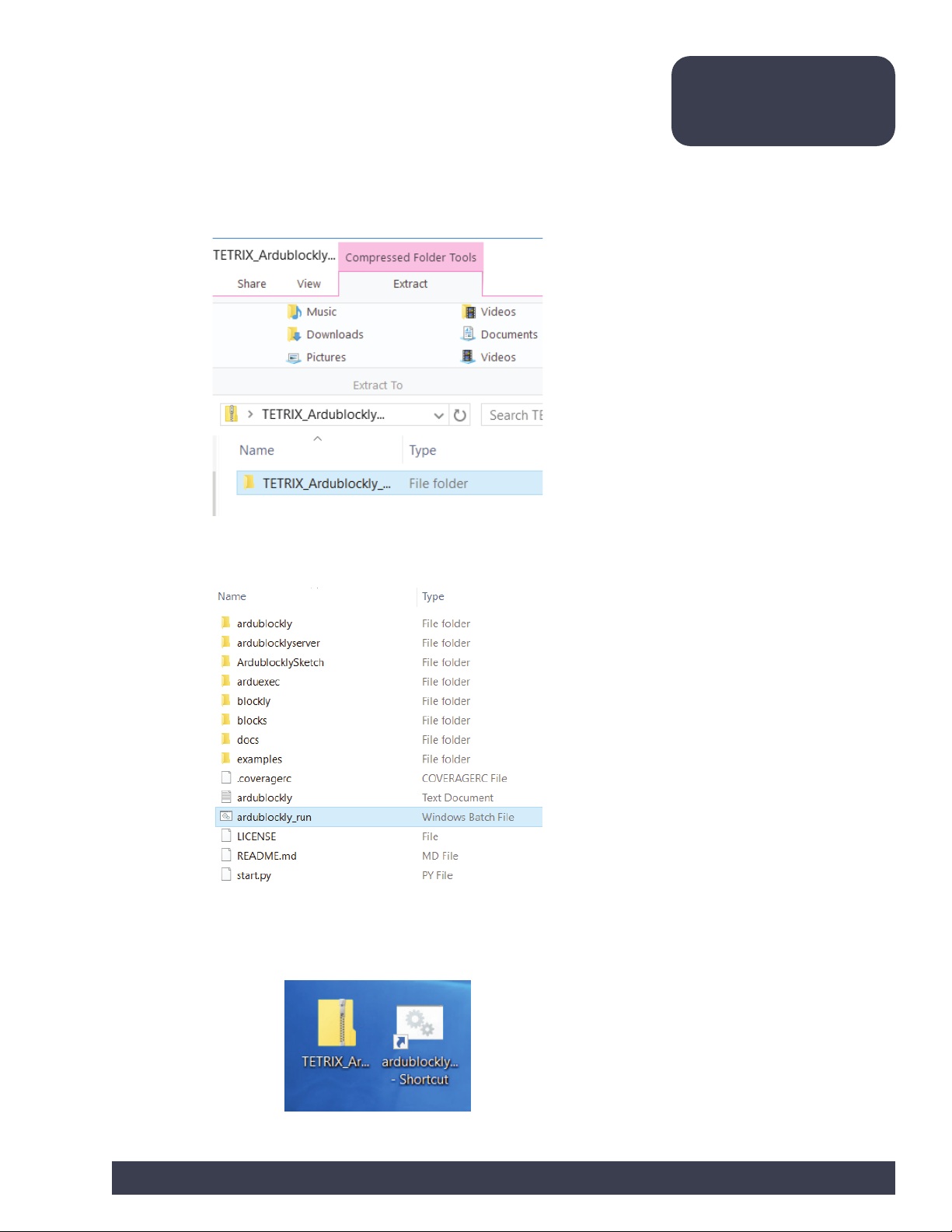
Place the downloaded file on the hard drive of your machine. Choose to extract the
zipped folder (Figure 5).
Note: This software will not
work on a 32-bit Windows
machine.
Figure 5
Locate the ardublockly_run file (Figure 6).
Figure 6
Create a shortcut and place it on your desktop (Figure 7). Do not delete the
extracted folder. It must remain on your machine to run the software.
Figure 7
Getting Started 15
Page 18
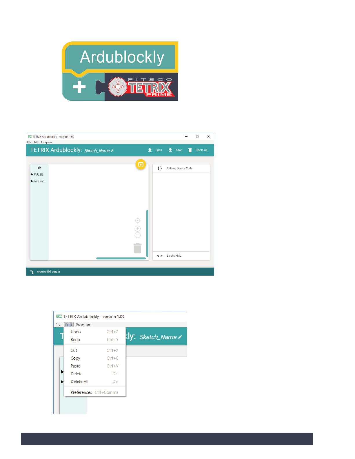
You will see the TETRIX Ardublockly icon show up on your desktop while it’s loading
the software (Figure 8).
Figure 8
When the software is loaded, you should see this screen (Figure 9).
Figure 9
Navigate to Edit > Preferences (Figure 10).
Figure 10
16 Getting Started
Page 19
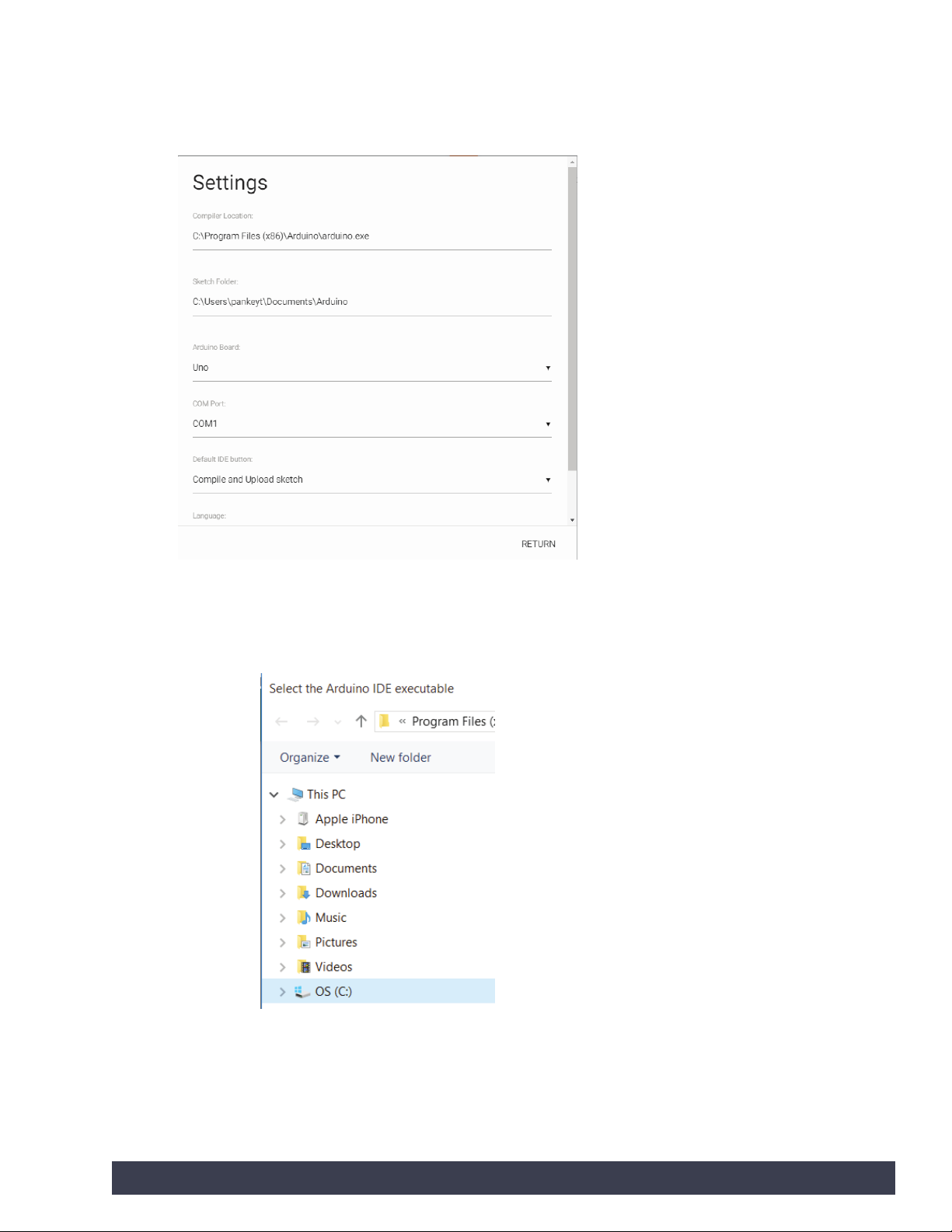
You will need to adjust the settings in the software. Make sure the compiler location
links to where the Arduino Software (IDE) is located on your device (Figure 11).
Click below Compiler Location.
Figure 11
Choose your operating system folder (Figure 12).
Figure 12
Getting Started 17
Page 20
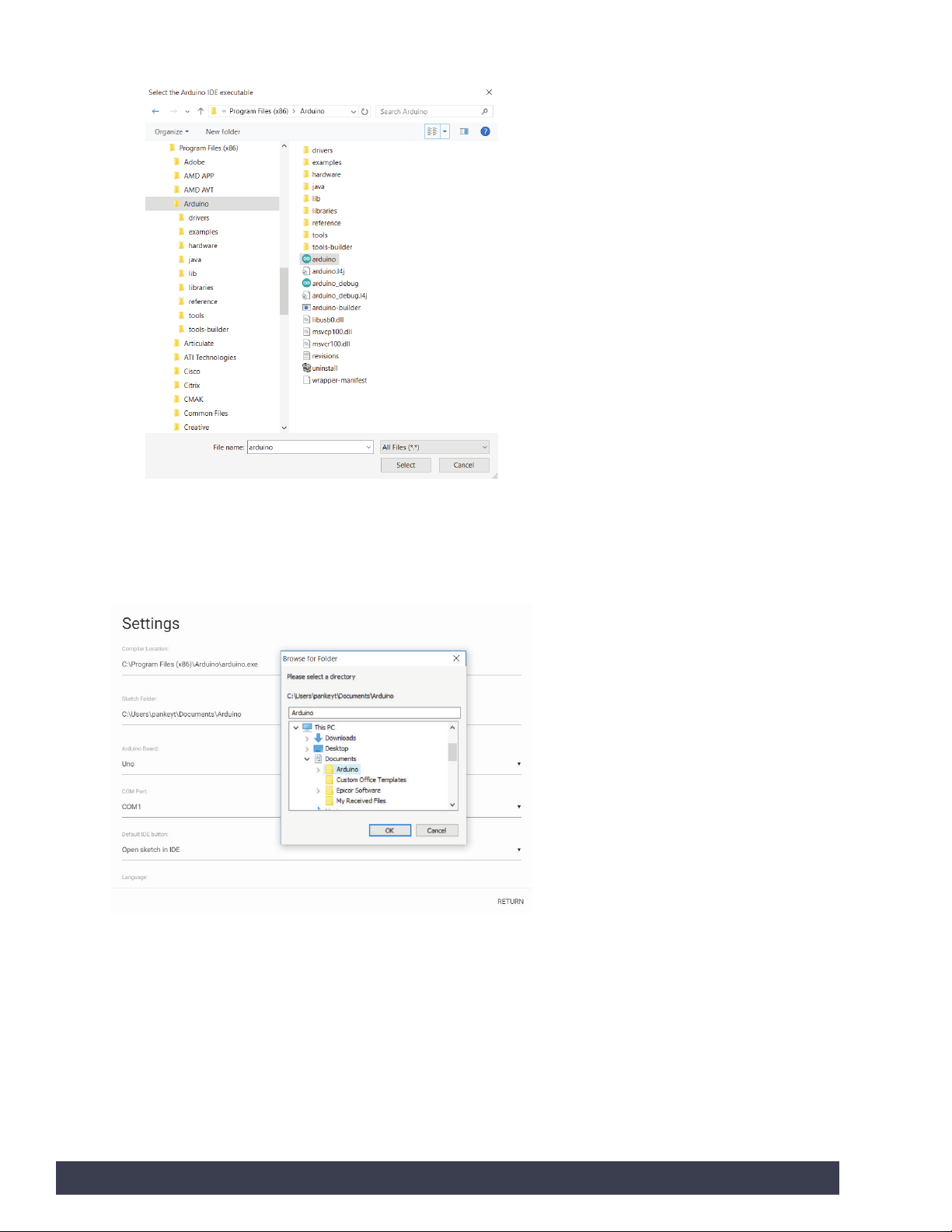
Find the Arduino program files. Select the Arduino application (Figure 13).
Figure 13
Click below Sketch Folder. Choose which location the sketch folder will save to. You
can save to your Documents folder or another location on your device (Figure 14).
Figure 14
18 Getting Started
Page 21
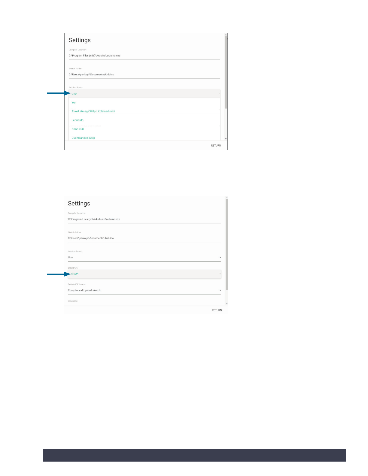
The Arduino board should be Uno (Figure 15).
Figure 15
Adjust the COM port to whichever port the PULSE controller is associated with
(Figure 16).
Figure 16
When this step is complete, your PULSE controller is connected to the TETRIX
Ardublockly software and coding can begin.
Getting Started 19
Page 22
TETRIX Ardublockly Introduction
Software Basics:
This is the main interface you will use when you open the software. On the far-left
side is the tool palette. To hide the tool palette, click the eye icon on the top of the
bar. This tool palette contains two different types of blocks. These are blocks that
were specifically created for use with the PULSE controller. The Arduino blocks can
also be used for additional functions and programming.
In the middle is the programming space. This is where you will place your blocks
to create your program. On the bottom right of the programming space, there is a
trash can where you can place blocks to delete them. Also, the plus and minus signs
allow you to zoom in and out of the programming space. The bull’s-eye will center
the programming space to where your blocks are placed.
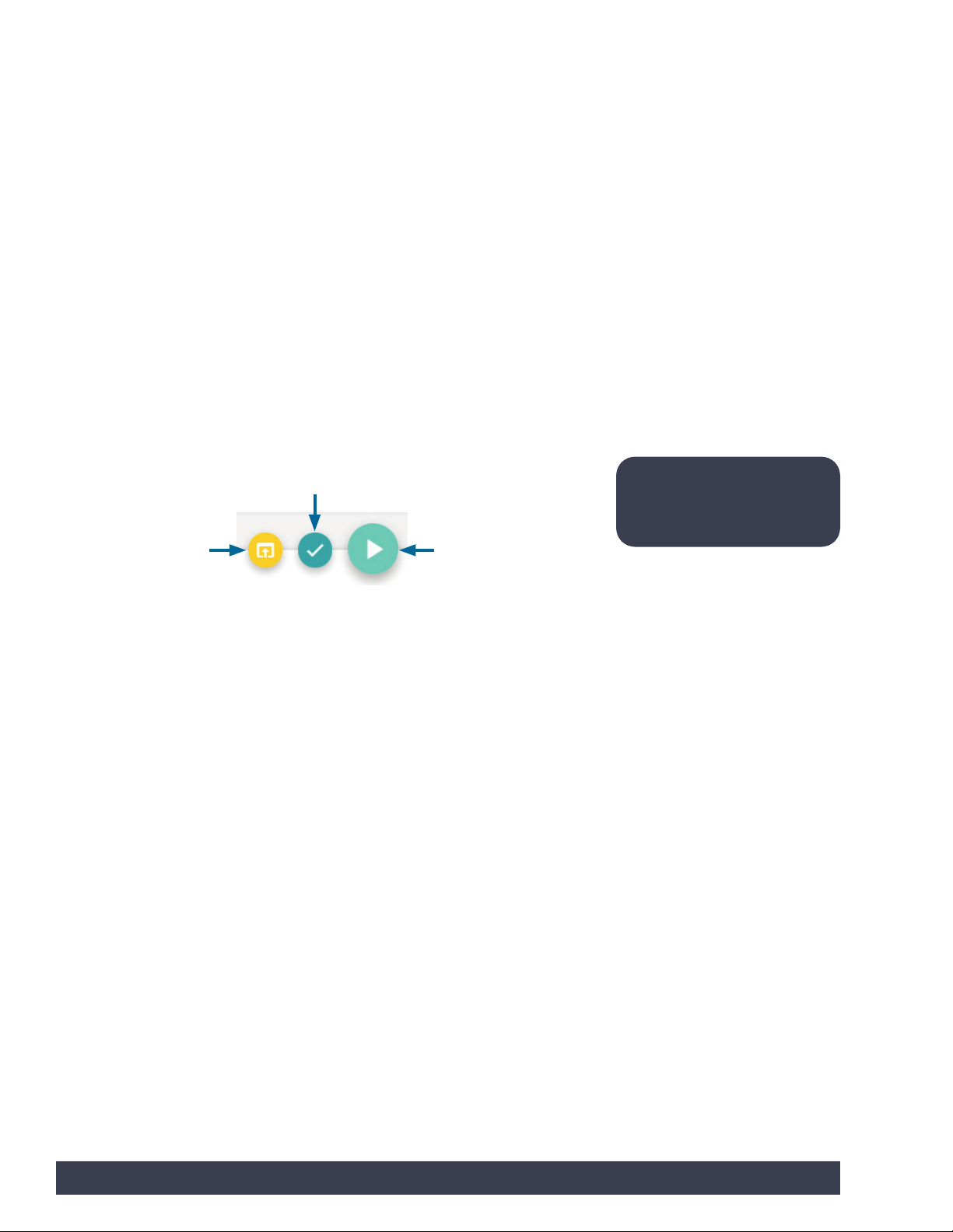
On the top right of the programming space, there are three buttons. One button is
Open Sketch, which allows you to open your sketch in the Arduino Software (IDE).
Your program will be opened in syntax format. You can edit the syntax code within
Arduino Software (IDE) if desired. This process will not be covered in this guide. The
Verify button allows you to check your sketch to ensure that your program has no
errors. The final button is Upload. This is the button that transfers your program to
the PULSE controller (Figure 17).
Verify
Open Sketch Upload Sketch
Figure 17
The far-right side shows the text-based Arduino source code. You can’t edit the
source code. You can hide the source code bar if desired.
On the very bottom of the screen, there is the Arduino IDE output command bar. It
defaults to being hidden. If you click anywhere along the bottom bar, it will open
the status bar. This provides real-time information on the status of an upload.
To name your program, click where it says Sketch_Name and type in your file
name. You must click Save to keep a copy of the program you create. If you are
opening an existing file, you can click Open.
Note: These buttons will
change order to show the
last button action chosen.
20 Getting Started
Page 23
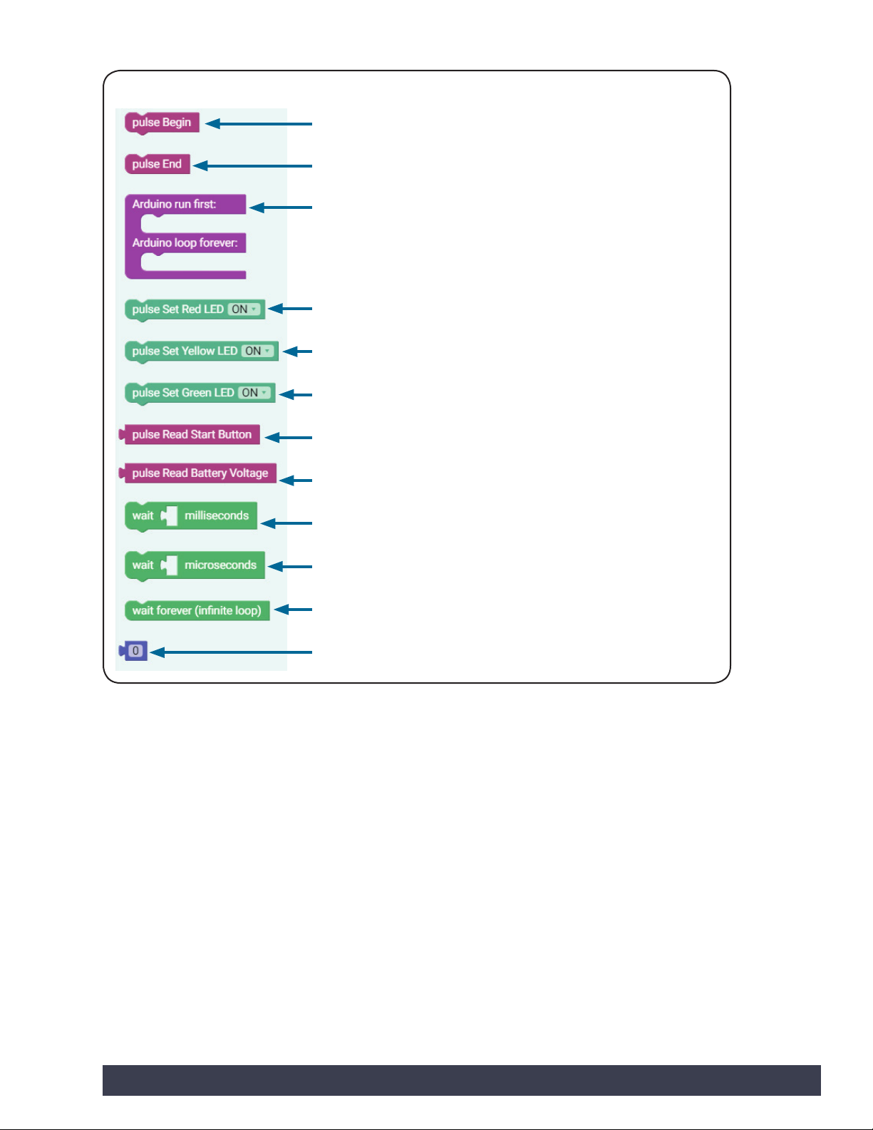
PULSE Blocks:
Control
Initializes the PULSE Robotics Controller
Immediately terminates the program
Defines the Arduino setup() and loop() functions
Sets the state of the PULSE red LED
Sets the state of the PULSE yellow LED
Sets the state of the PULSE green LED
Reads the state of the PULSE Start button
Reads the battery pack voltage
Waits for a specific time in milliseconds
Waits for a specific time in microseconds
Waits indefinitely, infinite loop
Time element (mini block that is attached to other blocks and edited)
Figure 18
Getting Started 21
Page 24
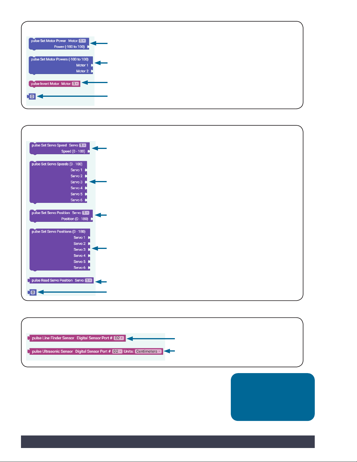
Motors
Servos
Sets the power and direction of the DC motor; the power range is -100 to 100
Sets the power and direction of DC Motors 1 and 2
Inverts the rotational direction of the selected motor channel
Time element
Figure 19
Sets the speed of the selected servo motor channel
Sets the speeds of all six servo motor channels
Sensors
Sets the position of the selected servo to a position between 0 and 180 degrees
Sets the positions of all six servo motor channels
Reads the position of the selected servo and stores it in a variable
Time element
Figure 20
Reads the output value of the Line Finder Sensor
Reads the output value of the Ultrasonic Sensor
in centimeters or inches
Figure 21
Tip: There are a variety
of additional blocks that
perform specific functions
in the Arduino drop-down
menu.
22 Getting Started
Page 25

Troubleshooting Tips:
• Your sketch always has to start with the pulse Begin block. If you want to
end a program, you can use the pulse End block or press the red Stop/Reset
button on the controller.
• If your sketch won’t load onto the PULSE controller, try disconnecting the USB
cable and reconnecting it. You can also try closing the software and opening
it again.
• Open your sketch in the Arduino IDE output window to see if you have
coding errors.
• Remember that you can use the resources in the appendix if you need
additional information.
• Want to see it in action? You can by watching the RoboBench video series for
the PULSE Programming Guide. You can find the entire series at
video.tetrixrobotics.com or on the TETRIXrobotics YouTube channel.
Getting Started 23
Page 26

Getting Started Activities
Now, it is time to get started with the activities. Each of the five getting started
activities is designed to introduce you to the TETRIX Ardublockly software and how
it works with the PULSE and select basic hardware. Success with these first five
activities will demonstrate how easy it is to use TETRIX Ardublockly software with the
PULSE and prepare you for coding the PULSE Codee Bot.
The TETRIX Ardublockly Sketch
As you begin creating your first sketch, it is necessary to understand some basic
rules about sketches. It is best to think of a sketch as a list of instructions to be
carried out in the order that they are written down. Each sketch will have several
instructions, and typically each instruction will be one block within the sketch.
Each block also represents lines of text known as code, which is why programming
is sometimes called coding. Text-based programming is also known as syntax
programming. TETRIX Ardublockly uses visual programming, also known as graphic
programming.
Many times, the best way to learn how to code is by following an example. In the
following activities, you will work through several coding examples to better learn
how to create sketches and upload them to the PULSE controller.
Note: If you are already
comfortable with coding in
Arduino sketches and want
to jump ahead, an overview
of each library function can
still be a helpful starting
point. We have created
and included definitions of
the functions along with
descriptions that show how
each would appear in an
Arduino sketch. You can find
these in the appendix of this
guide on pages 132-138.
More library functions might
be added in the future as the
library is updated to newer
versions.
Note: In addition to the
PULSE library, there is an
entire collection of Arduino
language commands that
are necessary to understand
before we can create
functional programs. The
Arduino language reference
as well as numerous
language learning tutorials
can be found by visiting the
Arduino homepage at
www.arduino.cc.
24 Getting Started Activities
Page 27
Activity 1: Hello World!
Introduction
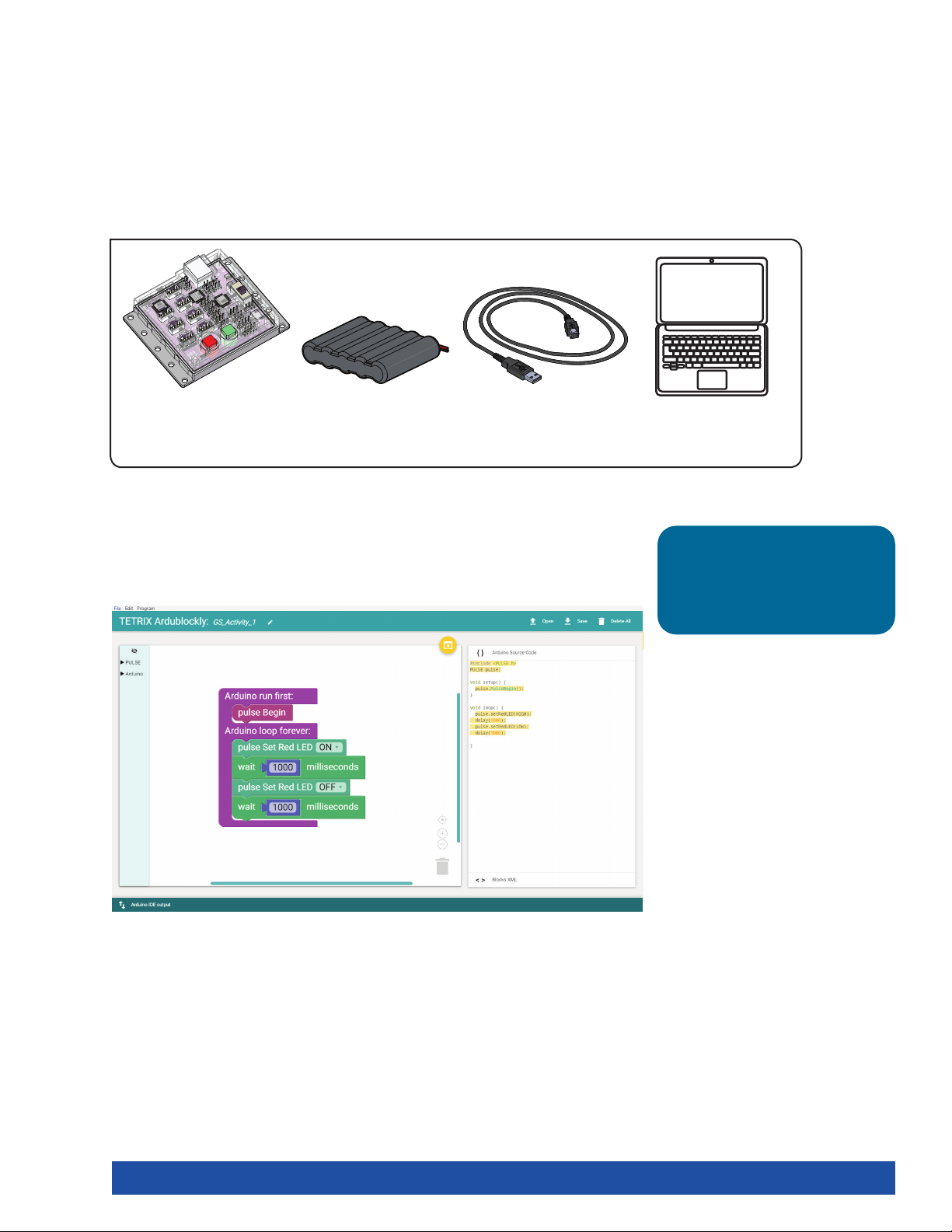
You will create a simple program, or sketch, that will blink the red LED on the
PULSE controller. Think of the controller as if it’s winking at you! This activity is the
equivalent of a Hello World! program, which is usually the intro activity for any new
programmer. The sketch you will create is a simple and basic PULSE code. All you
need is the PULSE controller, a power source, and a USB connection to the computer.
Parts Needed
1x
TETRIX® PULSE™
6 V NiMH Battery
Controller 44268
Open the Program
Let’s start by looking at the first example sketch. Open the sketch by selecting
Examples > GS_Activity_1. A new sketch window will open titled GS_Activity_1
(Figure 22).
1x
Pack 40235
1x
3-Foot Type A-B USB
Cable 40967
1x
Computer
Tip: Can’t find the program?
Check the Arduino Software
(IDE) Setup section on pages
10-11.
Figure 22
Getting Started Activities 25
Page 28
Background
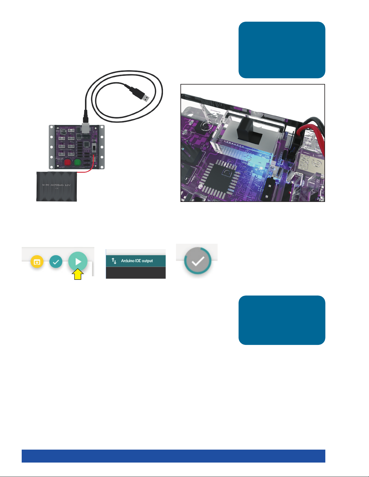
Before you can upload the sketch to the PULSE, you need to make sure the PULSE
has power, is connected to the computer, and is detected by the computer.
When the PULSE is connected as shown, turn on the PULSE with the on/off switch.
You will know the PULSE has power by the glowing blue light.
Tip: To see if the PULSE is
detected by the computer,
check the port as you did
in the Configuring USB
Communication section on
pages 12-14.
Execute the Code
To upload the sketch to the PULSE, click Upload Sketch (Figure 23). To check the
status of the upload, click Arduino IDE output on the bottom of the program (Figure
24).
Figure 23
Watch the Upload Sketch button. A colored line will spin around the circle while the
upload is in progress (Figure 25). Be patient!
As the data uploads, the yellow LEDs on the PULSE controller will flash. When the
upload is finished, there will be a solid green LED light beside the red Stop/Reset
button. The green LED means the code is ready to execute. Press the green Start
button to execute the code. The red LED next to the Stop/Reset button will blink off
and on in one-second intervals. To stop the program, press the Stop/Reset button.
Congratulations! You have successfully uploaded your first sketch to the PULSE and
demonstrated the results to the world.
Figure 24
Figure 25
Tip: Wait, why is the time in
milliseconds? Programmers
use milliseconds for more
precise timing. 1,000
milliseconds equal 1 second.
26 Getting Started Activities
Page 29
Further Investigate
Look at the right side of the program. You see text with different punctuation. This
is called syntax, or text-based programming. Each block in the sketch is typically
represented by one line of text. Lines of text within a sketch are also known as code,
which is why programming is sometimes called coding.
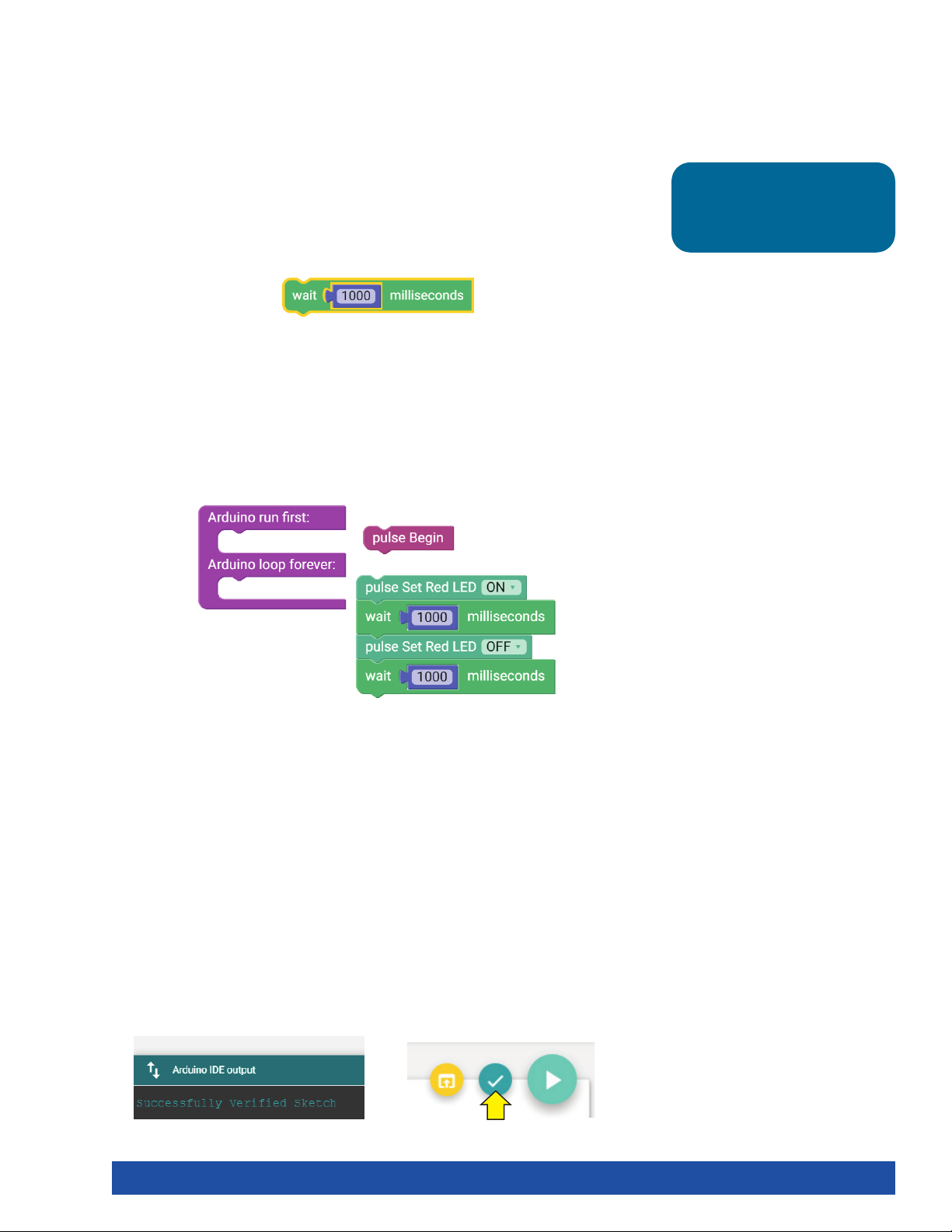
You can change some parameters in the sketch to see how they affect the behavior
of the red LED. The wait block determines how long the LED will be on and off
(Figure 26). This is a parameter you can change in your sketch. Experiment with
changing those values to create new blinking behaviors for the LED. Try making the
LED blink faster or slower.
Figure 26
Every program starts with a setup-loop block. Under the setup portion of the
block, the pulse Begin block always comes first. Any other blocks that need to be
set up only once are placed here. Blocks that will occur in a continuous loop in the
program are placed in the loop portion of the block.
In this example, the turning on and off of the red LED occurs over and over because
it is in a loop. Only terminating the program stops the program loop (Figure 27).
Tip: The time block is located
under the Motors category in
the software.
Figure 27
Extension Activity
With the example as a reference, try creating the blinking LED in a new sketch.
Instead of just blinking the red LED, try to blink the green LED too.
Flashing or blinking lights can be used for signaling or long-distance
communication. Challenge yourself to create a sequence of blinking LED lights like
a stoplight.
To start a new sketch, select File > New. Place the appropriate blocks into the
sketch. When you create your own sketch, there is a built-in software tool to help
ensure your code is free of errors. You can check your program by clicking Verify
the Sketch (Figure 28).
This will cause the code to compile but not upload. If there are errors in the code,
they will be displayed in the compiler error window at the bottom of the sketch
window (Figure 29). Errors will need to be corrected before code can be uploaded
to the PULSE controller.
Figure 28 Figure 29
Getting Started Activities 27
Page 30
If there are no errors, the compiler will complete and indicate that it is done
compiling, and you can upload your code. Click the Upload the Sketch button on
the sketch and see if you were able to simulate a stoplight.
Real-World Link
Think about the world around you. What things use blinking or flashing lights?
There are many examples such as traffic lights, holiday lights, and police lights. They
can serve as a warning or draw attention.
Careers: traffic technician, traffic light engineer, electronic engineer
STEM Connections
• Science
Ĕ Electricity
Ĕ LED lighting
• Technology
Ĕ Electronic design
Ĕ Traffic light programming
• Engineering
Ĕ Lighting types
Ĕ Optics
• Math
Ĕ Frequency
Ĕ Pattern
Tip: To solve this
extension activity, you
can find a sample sketch
in the appendix titled
GS_Activity_1_Extension_
Example.
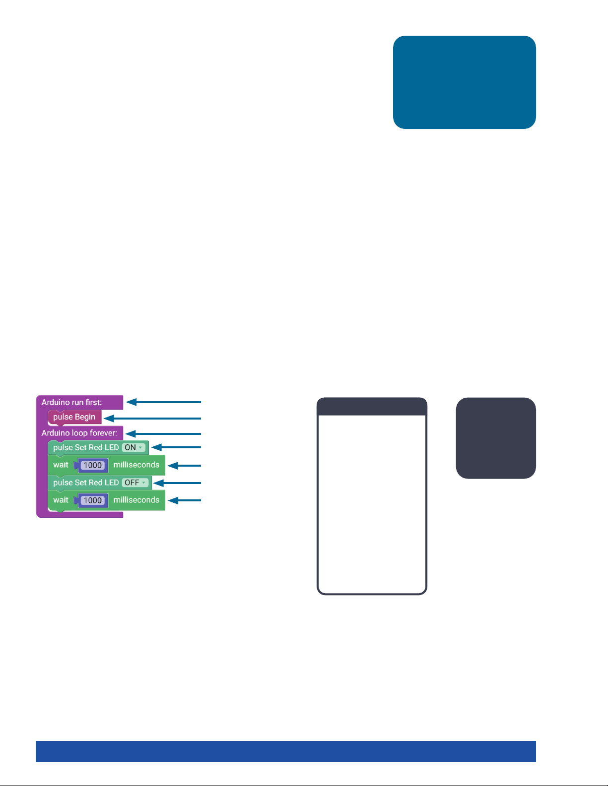
Block-Text Correlation
void setup() {
pulse.PulseBegin();
void loop() {
pulse.setRedLED(HIGH);
delay(1000);
pulse.setRedLED(LOW);
delay(1000);
Arduino Source Code
#include <PULSE.h>
PULSE pulse;
void setup() {
pulse.PulseBegin();
}
void loop() {
pulse.setRedLED(HIGH);
delay(1000);
pulse.setRedLED(LOW);
delay(1000);
}
Note: Notice
that On
means High
and Off
means Low.
28 Getting Started Activities
Page 31
Activity 2: Moving Your DC Motors
Introduction
For your second activity, you will add an element of motion. You will create a sketch
that will rotate a DC motor.
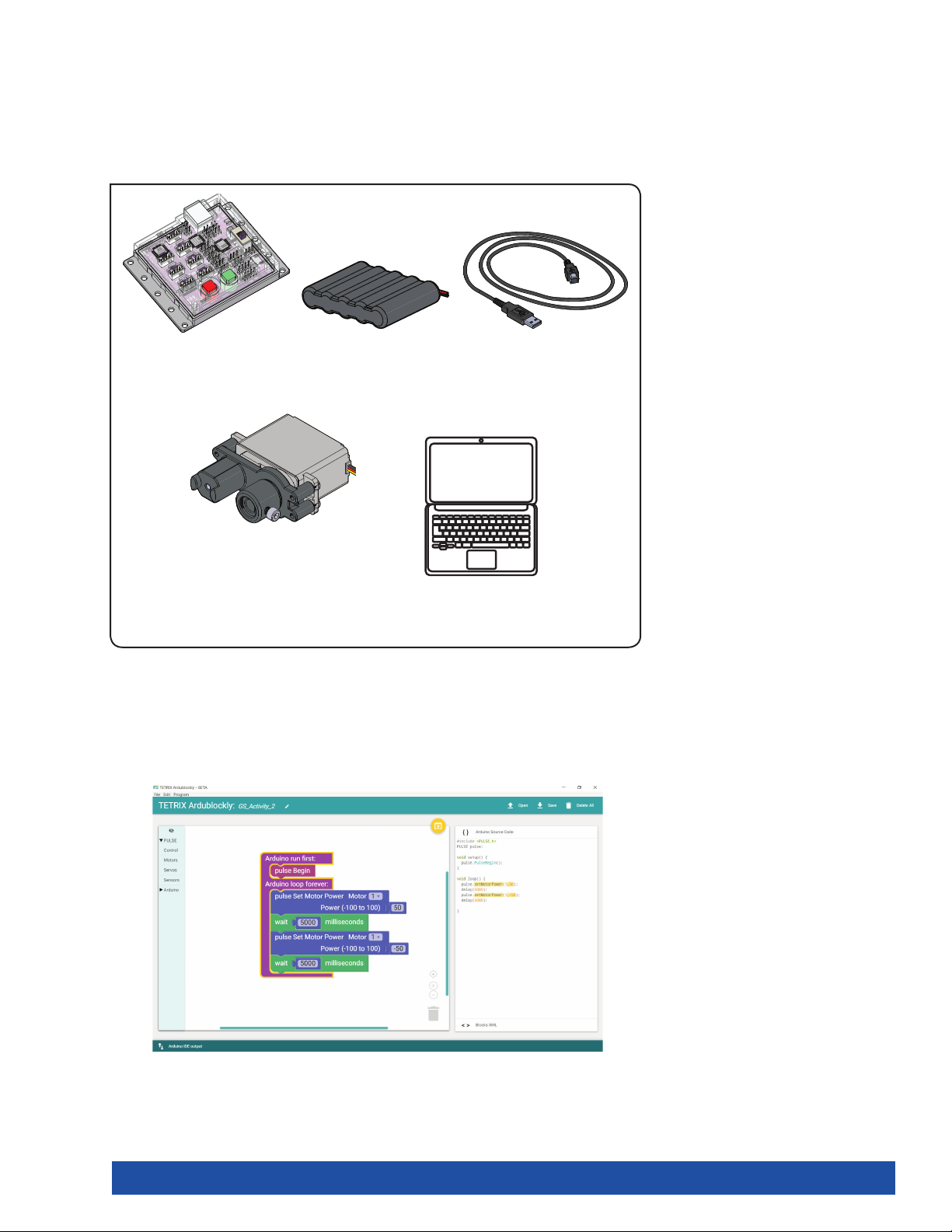
Parts Needed
1x
TETRIX® PULSE™
Controller 44268
6 V NiMH Battery
1x
Pack 40235
1x
3-Foot Type A-B USB
Cable 40967
1x
TETRIX DC Motor 44298
with Servo Mounting
Bracket 40232 (Assembly
instructions on pages
1x
Computer
54-55)
Open the Program
Before you open your next example sketch, be sure to save any sketch you want
to reference later. Let’s start by looking at the example sketch. Open the sketch by
selecting Examples > GS_Activity_2. A new sketch window will open titled GS_
Activity_2 (Figure 30).
Figure 30
Getting Started Activities 29
Page 32
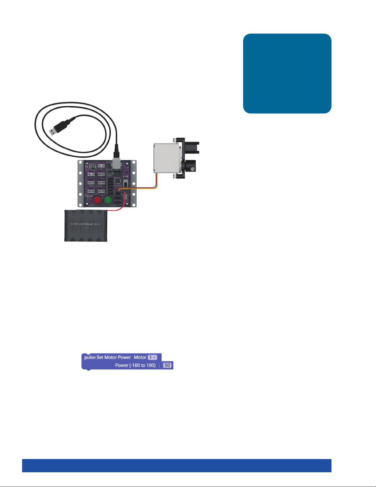
Background
The intent of this sketch is to spin a DC motor for five seconds and then stop. Then,
the motor will spin in the opposite direction for five seconds. The motor will operate
at half power. This behavior will continue until the Stop/Reset button is pressed.
Execute the Code
Before you can upload the sketch to the PULSE, remember to check your
connections. Keep in mind that you added a new connection with the motor. Plug
the end of the wire that extends from the DC motor into the DC Motor 1 port.
Tip: What’s the difference
between a DC motor and a
servo motor? A DC motor
has two wires and can rotate
continuously. A TETRIX servo
motor has three wires and
can be placed into different
positions but can’t rotate
beyond 180 degrees.
Upload the sketch. The green LED will light up, indicating that the code is ready
to execute. When this has happened, press the green Start button on the PULSE
controller.
Observe the direction and duration of the motor rotation. Did the motor’s behavior
match the intended program? Press the Stop/Reset button when you are ready to
stop the motor.
Further Investigate
The pulse Set Motor Power blocks allow you to adjust the percentage of power the
motor has. It can range from 0 (no power) to 100 (full power). If you wanted half
power, you would set the power to 50 (Figure 31).
Figure 31
30 Getting Started Activities
Page 33
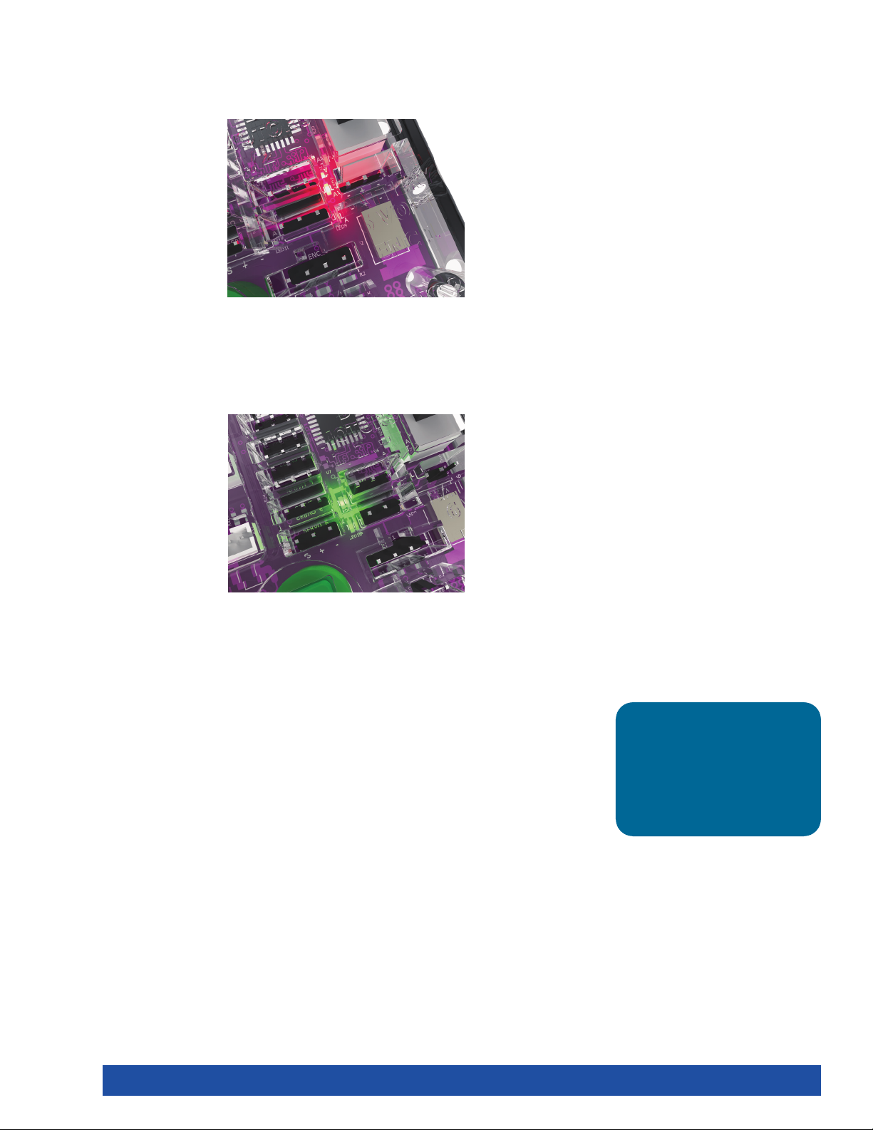
When the program is running, you will see a red light by the motor cord when
the motor is going forward, or clockwise. Within the sketch, this motor direction is
represented by a positive value (Figure 32).
Figure 32
When the program is running, you will see a green light by the motor cord when
the motor is going backward, or counterclockwise. Within the sketch, this motor
direction is represented by a negative value (Figure 33).
Figure 33
Practice changing the parameters in the sketch. You can change the motor power,
motor direction, stopping behavior, and delay between actions. Observe the effect
these changes have on the motor.
Extension Activity
With the example as a reference, try creating a new sketch using your DC motor
and LEDs on the controller. Remember what you learned from your first activity and
come up with a creative way to include blinking LEDs with your rotating motor.
Tip: To solve this
extension activity, you
can find a sample sketch
in the appendix titled
GS_Activity_2_Extension_
Example.
Getting Started Activities 31
Page 34
Real-World Link
You can find DC motors in many places. They are in elevators, trains, machinery,
power tools, cars, and fans. They are often used to power different electronics.
Careers: small-engine mechanic, mechanical engineer, machinery maintenance
worker
STEM Connections
• Science
Ĕ Direct current
Ĕ Power
• Technology
Ĕ DC motor use
Ĕ Torque
• Engineering
Ĕ Motor wiring
Ĕ Ground
• Math
Ĕ Revolutions per minute (rpm)
Ĕ Degrees
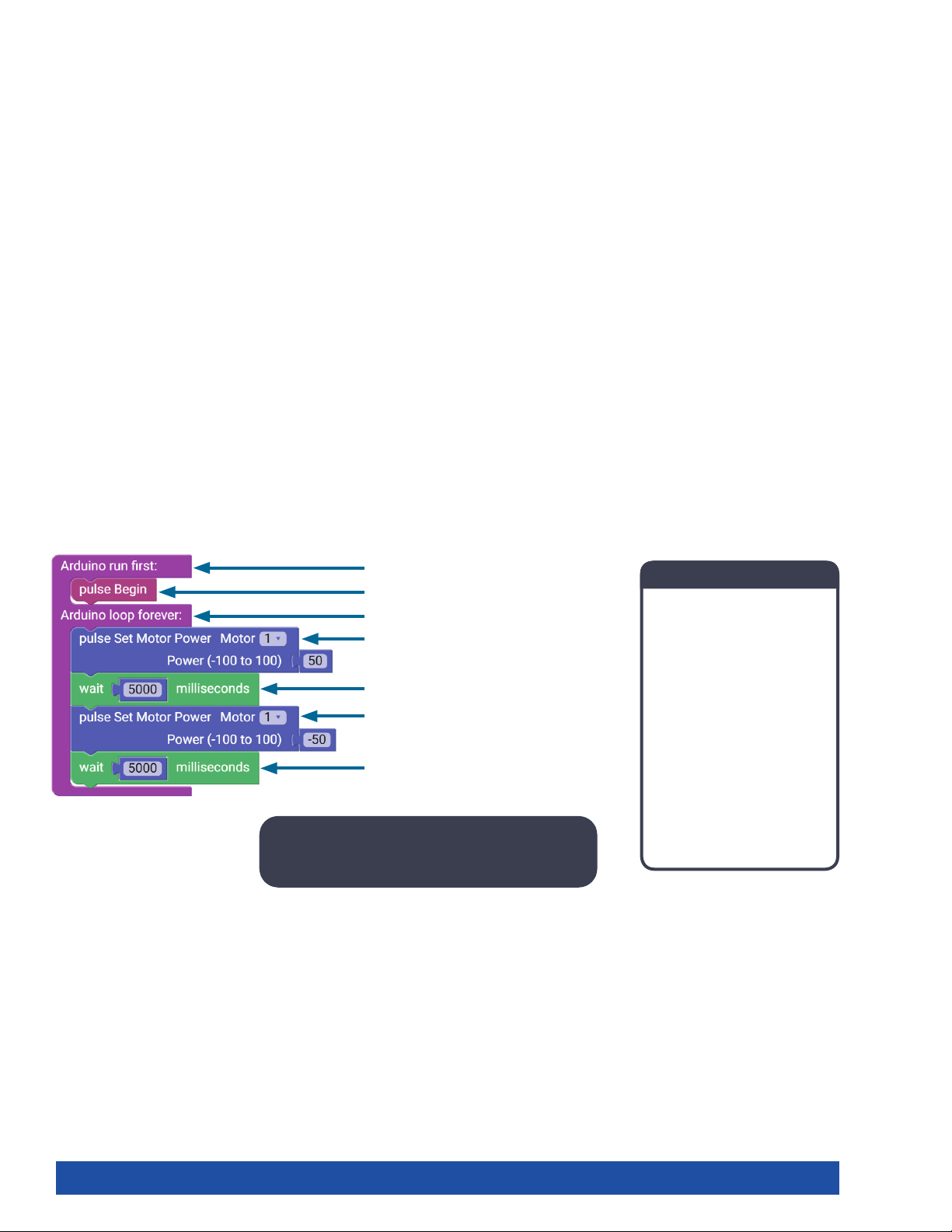
Block-Text Correlation
void setup() {
pulse.PulseBegin();
void loop() {
pulse.setMotorPower(1,50);
delay(5000);
pulse.setMotorPower(1,-50);
delay(5000);
Note: In the parentheses, (1,50) means Motor 1
will spin clockwise at a power of 50.
Arduino Source Code
#include <PULSE.h>
PULSE pulse;
void setup() {
pulse.PulseBegin();
}
void loop() {
pulse.setMotorPower(1,50);
delay(5000);
pulse.setMotorPower(1,-50);
delay(5000);
}
32 Getting Started Activities
Page 35
Activity 3: Moving Your Servo Motors
Introduction
In the third activity, you will create a sketch to rotate a servo motor. Servo motors
allow movement to a set position regardless of the start position. The TETRIX servo
motors have a limited range of motion from 0 to 180°. For example, you can tell a
servo to go to position 45° regardless of where it starts. If it starts at 0°, it will move
clockwise to 45°. If it starts at 120°, it will move counterclockwise to 45°.
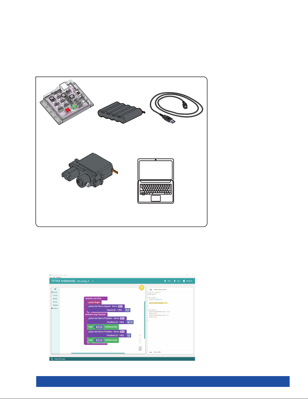
Parts Needed
1x
TETRIX® PULSE™
Controller 44268
6 V NiMH Battery
1x
Pack 40235
1x
3-Foot Type A-B USB
Cable 40967
1x
HiTec HS322-HD Servo
Motor 40538 with Servo
Mounting Bracket 40232
(Assembly instructions
1x
Computer
on pages 54-55)
Open the Program
Before you open your next example sketch, be sure to save any sketch you want
to reference later. Let’s start by looking at the example sketch. Open the sketch by
selecting Examples > GS_Activity_3. A new sketch window will open titled GS_
Activity_3 (Figure 34).
Figure 34
Getting Started Activities 33
Page 36
Background
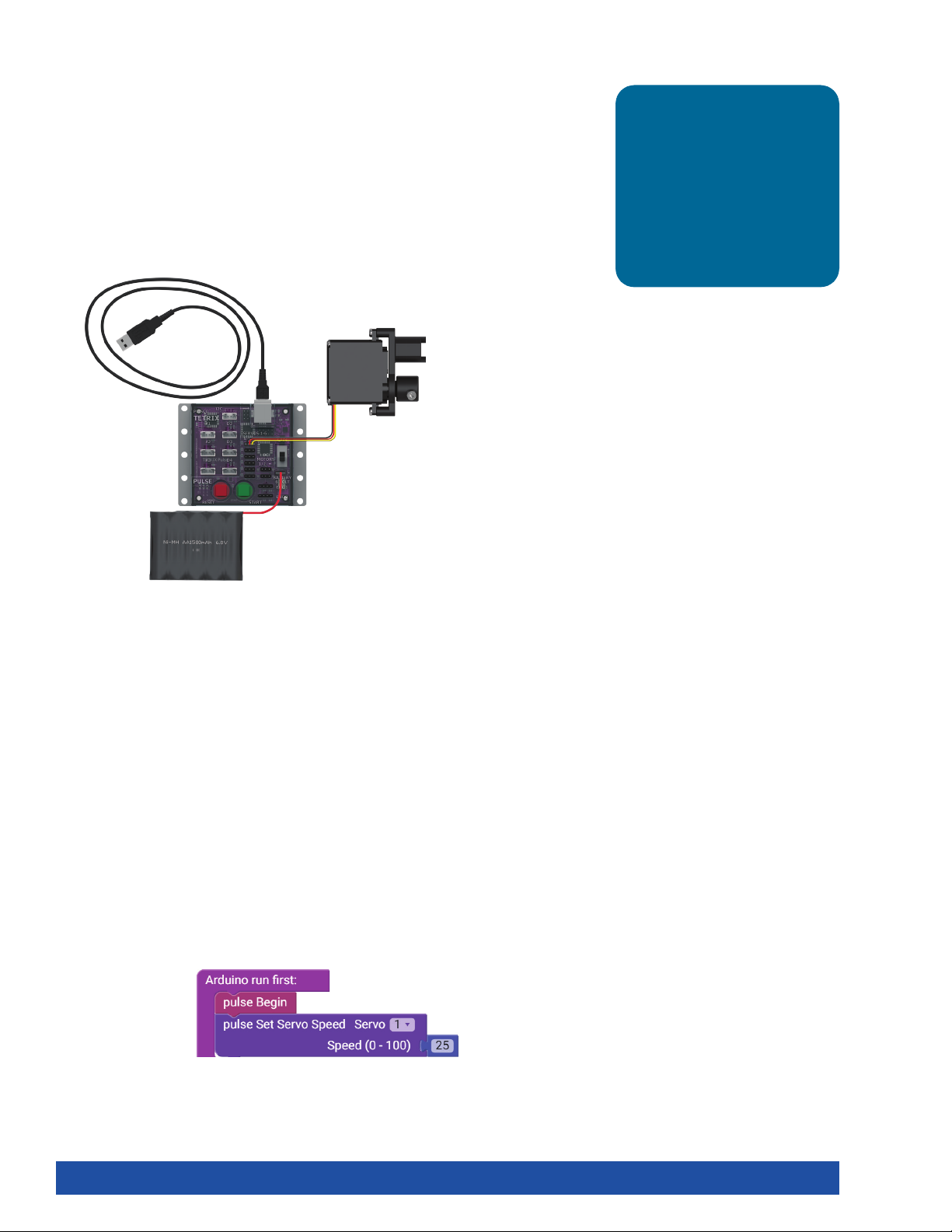
In this third sketch, you will spin a servo motor back and forth between two
different positions at a set speed. The motor will operate at 25% speed. This
behavior will continue until the Stop/Reset button is pressed.
Servo motors allow for a lot more precision in movement than DC motors do.
Execute the Code
Before you can upload the sketch to the PULSE, remember to check your
connections. Keep in mind that you added a new connection with the motor. Plug
the end of the wire that extends from a servo motor into the Servo 1 port.
Tip: What’s the difference
between a DC motor and a
servo motor? A DC motor
has two wires and can rotate
continuously. A TETRIX servo
motor has three wires and
can be placed into different
positions but can’t rotate
beyond 180 degrees.
Upload the sketch. The green LED will light up, indicating that the code is ready
to execute. When this has happened, press the green Start button on the PULSE
controller.
Observe the direction and duration of the servo motor rotation. Did the motor’s
behavior match the intended program? Press the Stop/Reset button when you are
ready to stop the motor.
Further Investigate
In this sketch, you will use two new PULSE blocks: pulse Set Servo Speed and pulse
Set Servo Position. Both blocks have two parameters, but they are different.
The two parameters of the pulse Set Servo Speed block are servo channel and servo
speed.
In the example, Servo 1 will spin at 25% power while it rotates to the position
commanded by the pulse Set Servo Position block. This block is in the setup portion
of the setup-loop block because it needs to be listed once at the beginning of the
program (Figure 35).
Figure 35
34 Getting Started Activities
Page 37
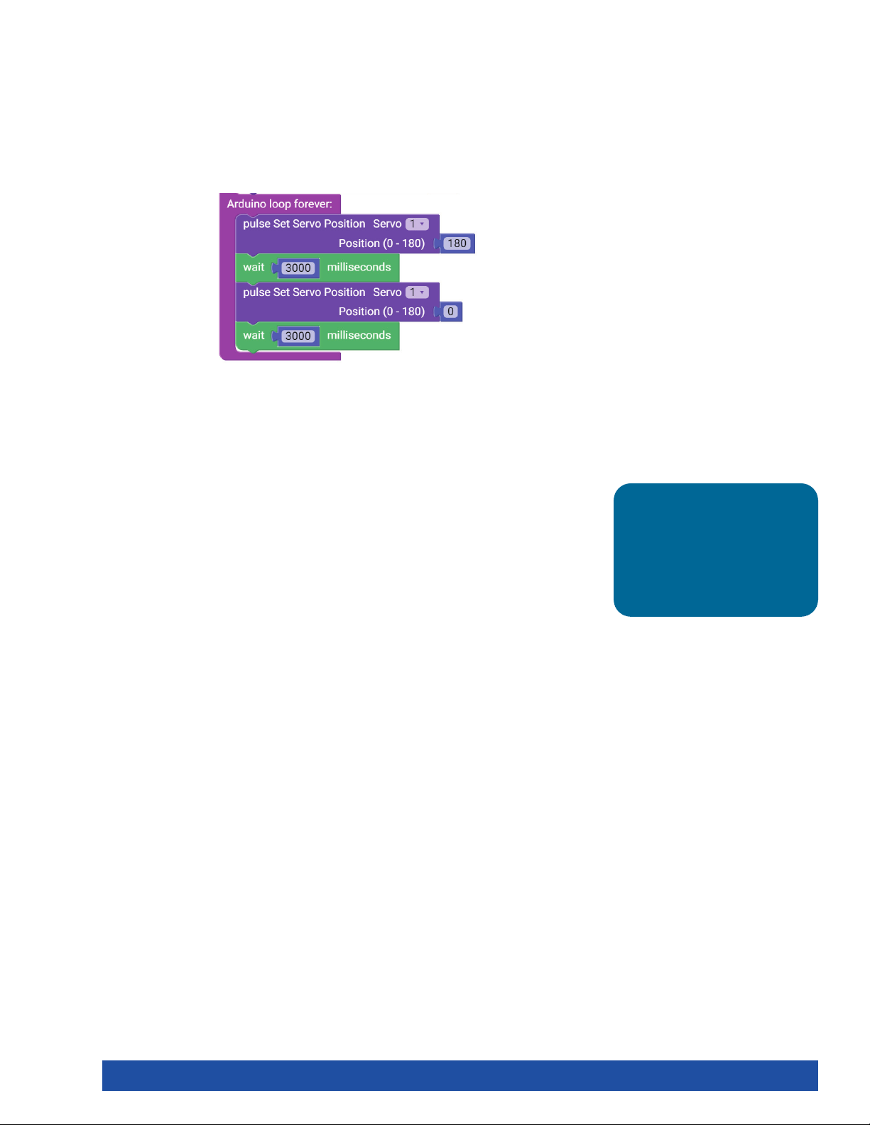
The two parameters of the pulse Set Servo Position block are servo channel and
target position. In the example, pulse Set Servo Position means Servo 1 will rotate
to the target position of 180°. It then changes position to 0° but continues at the
same speed.
This servo will continue to change position because the program will continue to
execute the loop until the program is ended (Figure 36).
Figure 36
In the sketch, both blocks work together to tell the servo motor not only the target
position but also the speed to use while moving to the target position.
You can alter the position and speed of the servo by changing the values of both
functions. Practice changing the parameters in the sketch. Observe the effect these
changes have on the servo motor.
Extension Activity
With the example as a reference, try creating a new sketch to move your servo
motor. You could also incorporate the use of your DC motor and LEDs on the
controller. Remember what you learned from your previous activities and think of
creative ways to combine the functions you have learned.
Tip: To solve this
extension activity, you
can find a sample sketch
in the appendix titled
GS_Activity_3_Extension_
Example.
Getting Started Activities 35
Page 38
Real-World Link
You can find servo motors in R/C model cars for steering and R/C model airplanes
for controlling flaps and rudders. Servos are used where precise movement is
needed such as in the operation of robotic arms, grippers, and rotating camera
mounts.
Careers: fabricator, industrial engineer, machinist
STEM Connections
• Science
Ĕ Current
Ĕ Fleming’s rules
• Technology
Ĕ Motor assembly
Ĕ Feedback system
• Engineering
Ĕ Energy conversion
Ĕ Motor gearing
• Math
Ĕ Accuracy
Ĕ Precision
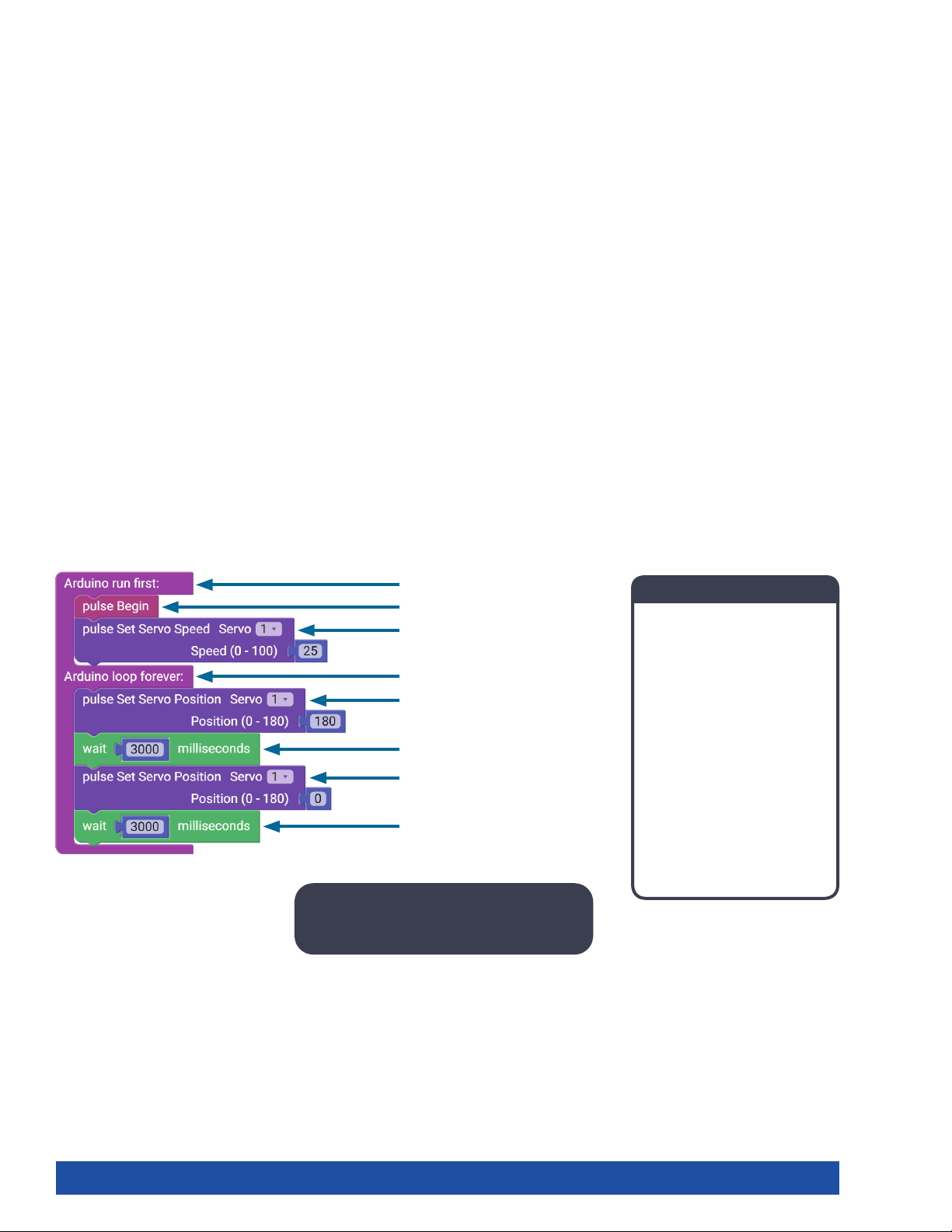
Block-Text Correlation
void setup() {
pulse.PulseBegin();
pulse.setServoSpeed(1,25);
void loop() {
pulse.setServoPosition(1,180);
delay(3000);
pulse.setServoPosition(1,0);
delay(3000);
Note: The servo motor changes position
from 0 degrees to 180 degrees.
Arduino Source Code
#include <PULSE.h>
PULSE pulse;
void setup() {
pulse.PulseBegin();
pulse.setServoSpeed(1,25);
}
void loop() {
pulse.setServoPosition(1,180);
delay(3000);
pulse.setServoPosition(1,0);
delay(3000);
}
36 Getting Started Activities
Page 39
Activity 4: Introduction to the Line Finder Sensor
Introduction
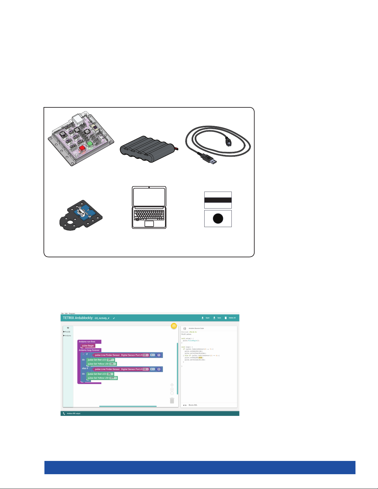
For the fourth activity, you will use a line-finding sensor. In this example, you will
connect a Line Finder Sensor to digital sensor port D2. You will create a sketch to
read digital input from the Line Finder Sensor.
Sensors enable us to gather information from the world around us. The type of
information depends on the type of sensor. The Line Finder Sensor uses reflected
infrared light to distinguish between light and dark surfaces.
Parts Needed
1x
TETRIX® PULSE™
6 V NiMH Battery
Controller 44268
1x
Line Finder Sensor
Pack 43056
Open the Program
Before you open your next example sketch, be sure to save any sketch you want
to reference later. Let’s start by looking at the example sketch. Open the sketch by
selecting Examples > GS_Activity_4. A new sketch window will open titled GS_
Activity_4 (Figure 37).
1x
Pack 40235
1x
Computer
1x
3-Foot Type A-B USB
Cable 40967
1x
Contrasting light
and dark surface
Figure 37
Getting Started Activities 37
Page 40
Background
For the fourth sketch, you will take a closer look at programming a sensor and using
a logic block. You will use the Line Finder Sensor to determine whether a surface is
light or dark.
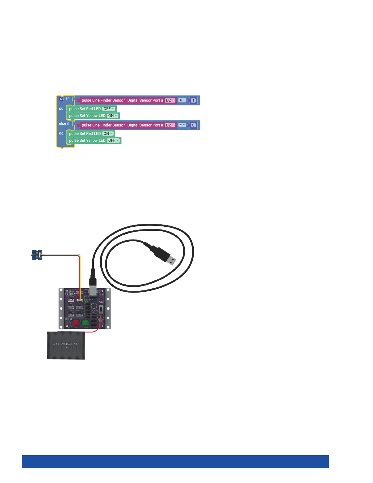
The if-do logic block does exactly what its name suggests. Everything contained
within the loop will repeat consecutively until the sketch is ended with a command
or the Stop/Reset button (Figure 38).
Figure 38
Depending on the surface, a red or yellow LED will light up on the PULSE controller.
Execute the Code
Before you can upload the sketch to the PULSE, remember to check your
connections. Keep in mind that you added a new connection in digital sensor port
D2 with the Line Finder Sensor.
Upload the sketch. The green LED will light up, indicating the code is ready to
execute. When this has happened, press the green Start button on the PULSE
controller.
Hold the sensor over a contrasting surface. As the sensor moves from light to dark,
observe the red LED on the PULSE. When the sensor is over a nonreflective or dark
surface, the yellow LED will be on. When the sensor is over a white or reflective
surface, the red LED will be on.
Press the Stop/Reset button when you are ready to stop the sensor.
38 Getting Started Activities
Page 41
Further Investigate
This sketch introduces a program structure, new blocks, and a comparison
statement. The program structure is an “if” statement, the reading of the sensor, and
the comparison statement is “=” (equal to). The comparison statement “=” (equal
to) defines a type of test. In this sketch, the input of the Line Finder Sensor will turn
different LEDs on or off.
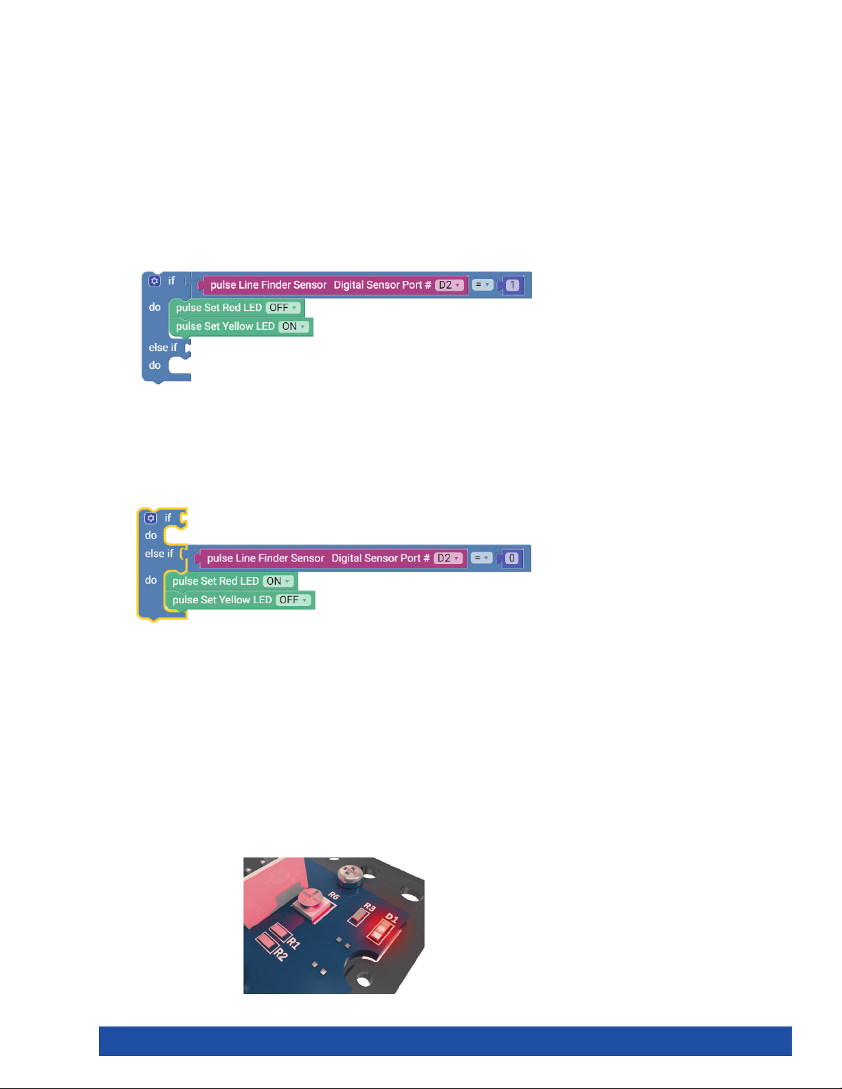
The basic “if” statement enables us to test for a certain condition. If this condition is
met, then the program can perform an action. If the variable in the if section of the
loop block is true, then the blocks within the do section are run. In this instance, the
output of the Line Finder Sensor must equal 1, or HIGH, for the do section to run
(Figure 39).
Figure 39
If the if portion of the loop block isn’t true, then the else if portion enables you to
test for a different condition. If this condition is met, then the blocks within the do
section under the else if section will run. In the else if portion, the output of the Line
Finder Sensor must equal 0, or LOW (Figure 40).
Figure 40
The Line Finder Sensor can return a value of “1” (HIGH) or “0” (LOW). A value of “1” is
returned when the Line Finder Sensor detects a dark line or a nonreflective surface;
a value of “0” is returned when the Line Finder Sensor detects a white or reflective
surface.
If the Line Finder Sensor detects a line or a nonreflective surface, then it turns
the red LED on. Think of it as an object placed in its path. The red LED on the Line
Finder Sensor also lights up. In the program, this occurs when the line variable is set
to LOW.
If the Line Finder Sensor detects a white or reflective surface, it turns the yellow LED
on. In the program, this occurs when the line variable is set to HIGH (Figure 41).
Figure 41
Getting Started Activities 39
Page 42
Experiment with the Line Finder Sensor on different surfaces and different heights
to see how the sensor reacts.
Extension Activity
With the example as a reference, try creating a new sketch to use your Line Finder
Sensor. Remember what you learned from your previous activities and think of
additional creative actions to perform based on the condition of the Line Finder
Sensor.
Real-World Link
There are many uses for a robot that can follow a line. Automated robots are being
developed to follow lines to deliver materials within hospitals. In the future, they
could also move materials around warehouses or transport goods.
Careers: materials engineer, electromechanical technician, software developer
STEM Connections
• Science
Ĕ Light
Ĕ Electromagnetic spectrum
• Technology
Ĕ Guidance system
Ĕ Automation
• Engineering
Ĕ Microcontroller
Ĕ Embedded system
• Math
Ĕ Angles
Ĕ Lines
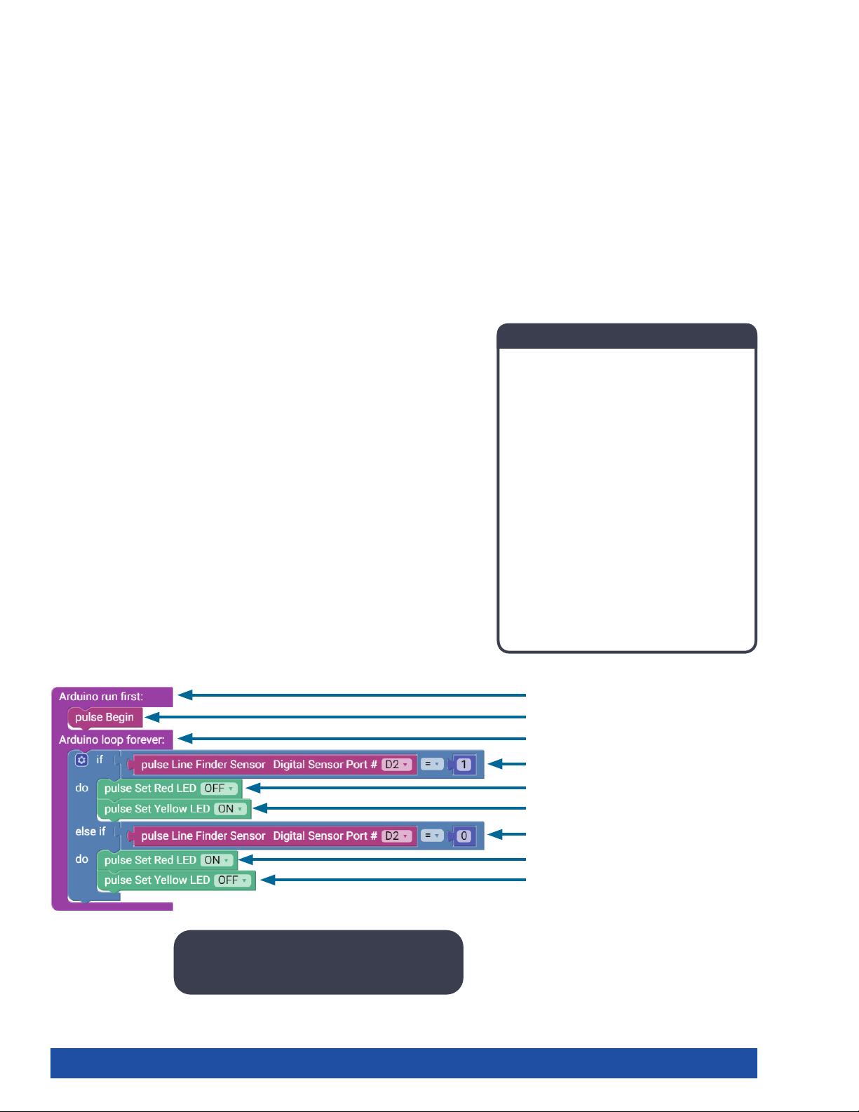
Block-Text Correlation
Arduino Source Code
#include <PULSE.h>
PULSE pulse;
void setup() {
pulse.PulseBegin();
}
void loop() {
if (pulse.readLineSensor(2) == 1) {
pulse.setRedLED(LOW);
pulse.setYellowLED(HIGH);
} else if (pulse.readLineSensor(2) == 0) {
pulse.setRedLED(HIGH);
pulse.setYellowLED(LOW);
}
}
Note: All the actions completed in the if () or
if/else () loops are contained within braces.
40 Getting Started Activities
void setup() {
pulse.PulseBegin();
void loop() {
if (pulse.readLineSensor(2) == 1) {
pulse.setRedLED(LOW);
pulse.setYellowLED(HIGH);
} else if (pulse.readLineSensor(2) == 0) {
pulse.setRedLED(HIGH);
pulse.setYellowLED(LOW);
Page 43
Activity 5: Introduction to the Ultrasonic Sensor
Introduction
For the final getting started activity, you will finish up your exploration of sensors
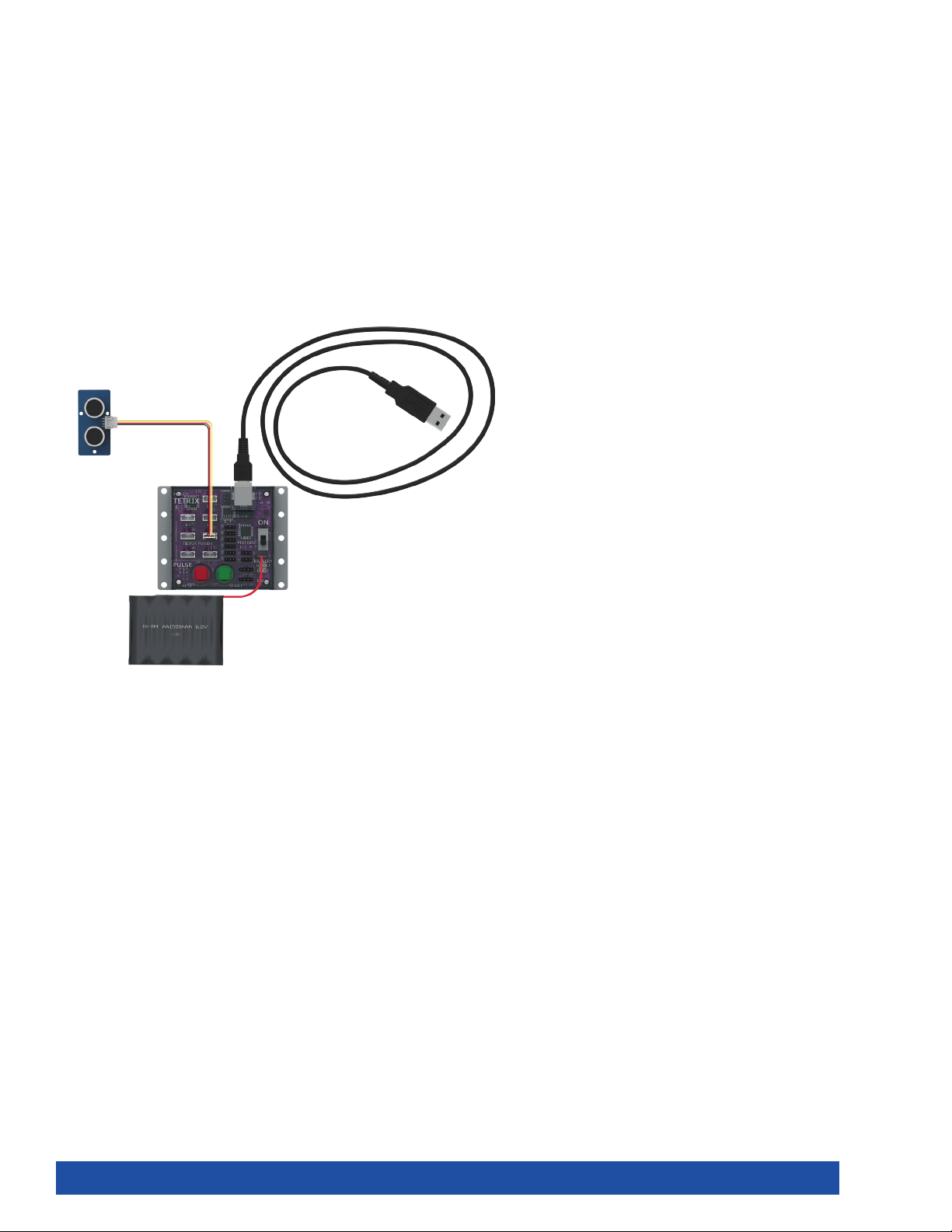
by creating a sketch using the Ultrasonic Sensor. In this activity, you will connect
an Ultrasonic Sensor to digital sensor port D3 and display the distance to an object
you place in front of it using the serial monitor window.
Like all sensors, the Ultrasonic Sensor enables us to gather information. The
Ultrasonic Sensor gathers information to communicate distance. The sensor works
by sending a sonic pulse burst and then waiting on its return as it is reflected off an
object in range. The reflected sonic pulse time period is measured to determine the
distance to the object. The sensor has a measuring range of approximately 3-400
centimeters.
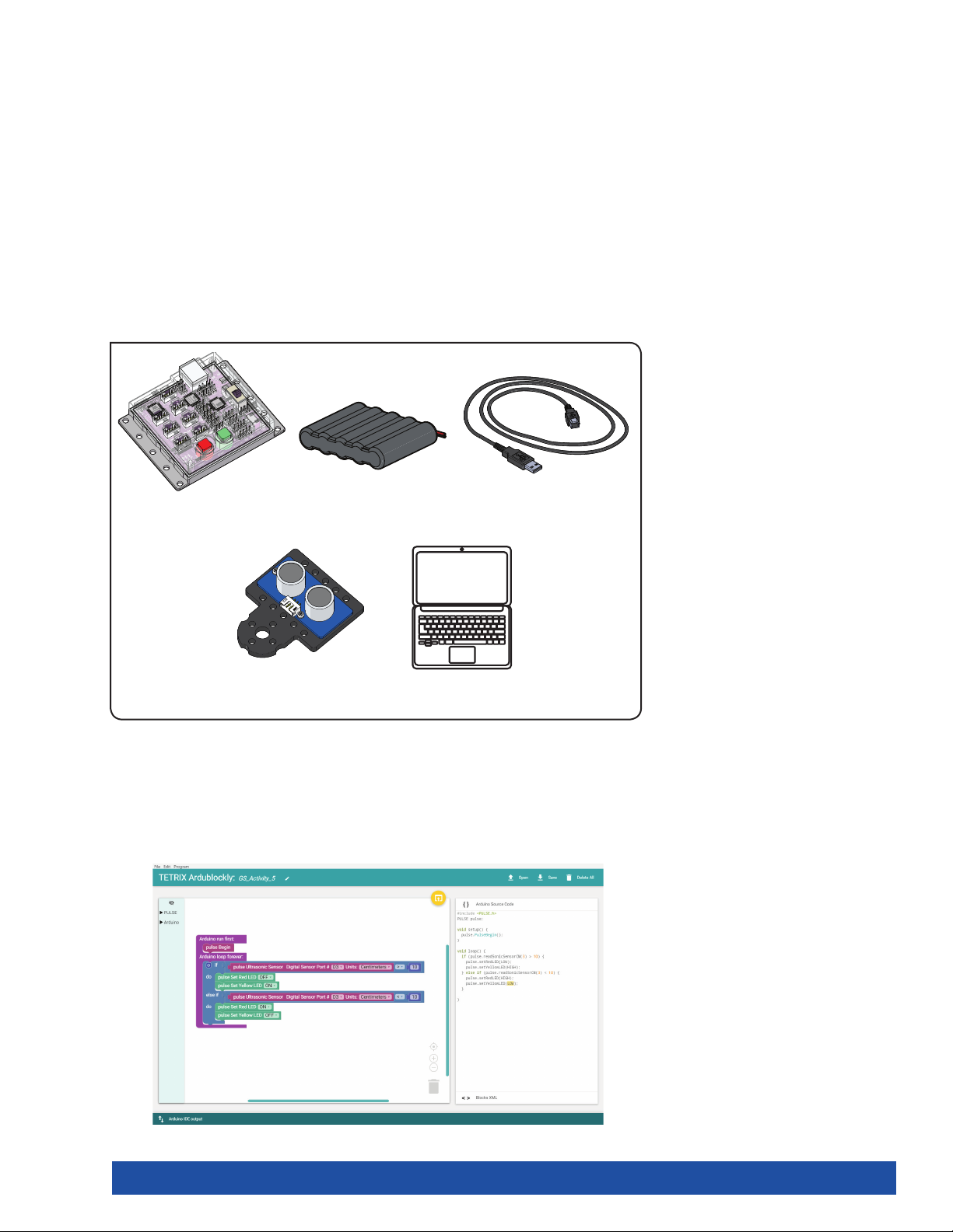
Parts Needed
1x
TETRIX® PULSE™
Controller 44268
1x
6 V NiMH Battery
Pack 40235
3-Foot Type A-B USB
1x
Cable 40967
1x
Ultrasonic Sensor
Pack 43055
Open the Program
Before you open your next example sketch, be sure to save any sketch you want
to reference later. Let’s start by looking at the example sketch. Open the sketch by
selecting Examples > GS_Activity_5. A new sketch window will open titled GS_
Activity_5 (Figure 42).
1x
Computer
Figure 42
Getting Started Activities 41
Page 44
Background
For your fifth sketch, you will use the Ultrasonic Sensor, which sends out pulses that
measure the distance from the sensor to the object. You will use the same logic
block from the previous activity.
Instead of measuring light, this sensor will measure distance. Depending on the
distance of the object from the sensor, a red or yellow LED will light up on the
PULSE controller.
Execute the Code
Before you can upload the sketch to the PULSE, remember to check your
connections. Keep in mind that you added a new connection in digital sensor port
D3 with the Ultrasonic Sensor. Upload the sketch.
With the sensor lying flat on the desk pointed up, press the green Start button to
execute the code.
Hold your hand above the sensor. Move it up and down. Watch what happens to
the LEDs on the PULSE controller. Press the Stop/Reset button when you are ready
to stop the sensor.
42 Getting Started Activities
Page 45
Further Investigate
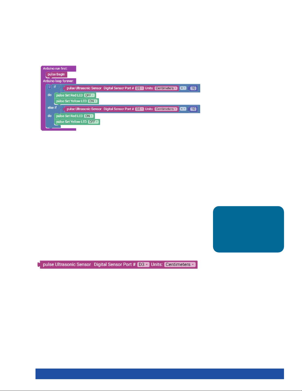
In this sketch, the input of the Ultrasonic Sensor will turn different LEDs on or off.
If the variable in the if section of the loop block is true, then the blocks within the
do section of the loop block are run. In this instance, if there isn’t an object closer
than 10 cm to the Ultrasonic Sensor, the yellow LED on the PULSE controller will be
lit (Figure 43).
Figure 43
If the if portion of the loop block isn’t true, then the else if portion enables you to
test for a different condition. If this condition is met, then the blocks within the do
section under the else if section will run. In this instance, if there is an object closer
than 10 cm to the Ultrasonic Sensor, the red LED on the PULSE controller will be lit.
Experiment with the Ultrasonic Sensor with different objects and different heights
to see how the sensor reacts.
Extension Activity
With the example as a reference, try creating a new sketch to use your Ultrasonic
Sensor. Remember what you learned from your previous activities and experiment
with different objects in front of the Ultrasonic Sensor to see if they are detectable.
You can also program the motors to stop when an object reaches a certain distance
from the Ultrasonic Sensor.
Try changing the distance units on the pulse Ultrasonic Sensor block from
centimeters to inches. Understanding how to use the Ultrasonic Sensor will give
your robot vision so that it can steer around objects and obstacles (Figure 44).
Figure 44
Tip: To solve this
extension activity, you
can find a sample sketch
in the appendix titled
GS_Activity_5_Extension_
Example.
Getting Started Activities 43
Page 46
Real-World Link
Modern vehicles are smart. They have backup cameras and assisted parallel
parking and will even beep at you if an object is too close to the car. This is how an
ultrasonic sensor works!
Careers: car designer, sound engineering technician, sonar technician
STEM Connections
• Science
Ĕ Sound waves
Ĕ Reflection of sound waves
• Technology
Ĕ Frequency
Ĕ Sound digitization
• Engineering
Ĕ Sonic measurements
Ĕ Sonar
• Math
Ĕ Distance
Ĕ Comparison symbols
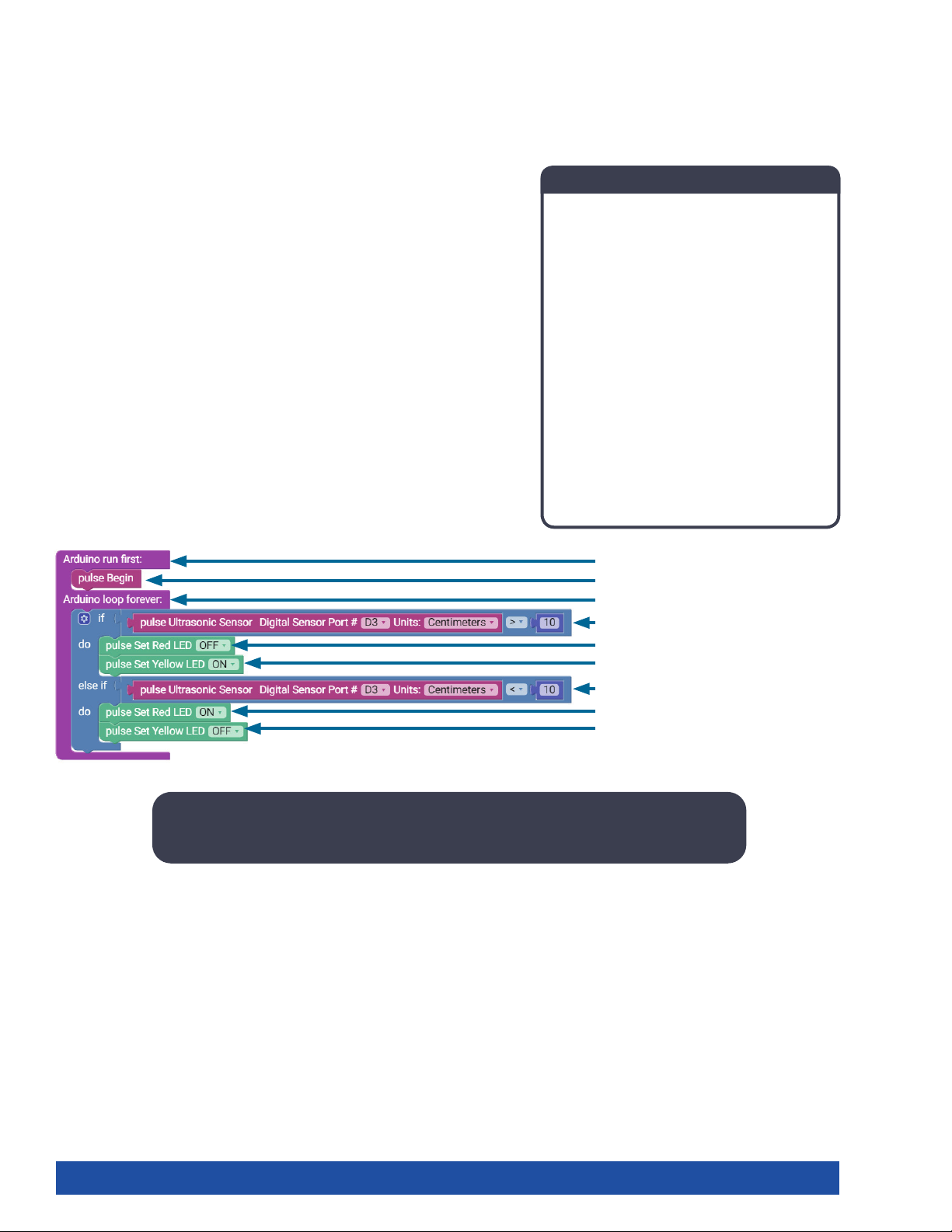
Block-Text Correlation
Arduino Source Code
#include <PULSE.h>
PULSE pulse;
void setup() {
pulse.PulseBegin();
}
void loop() {
if (pulse.readSonicSensorCM(3) > 10) {
pulse.setRedLED(LOW);
pulse.setYellowLED(HIGH);
} else if (pulse.readSonicSensorCM(3) < 10) {
pulse.setRedLED(HIGH);
pulse.setYellowLED(LOW);
}
}
void setup() {
pulse.PulseBegin();
void loop() {
if (pulse.readSonicSensorCM(3) > 10) {
pulse.setRedLED(LOW);
pulse.setYellowLED(HIGH);
} else if (pulse.readSonicSensorCM(3) < 10) {
pulse.setRedLED(HIGH);
pulse.setYellowLED(LOW);
Note: This program uses the math values of greater than (>) and less than (<). A specific
LED will be lit depending on whether the output value is greater than or less than 10.
44 Getting Started Activities
Page 47
Building and Coding the PULSE Codee Bot
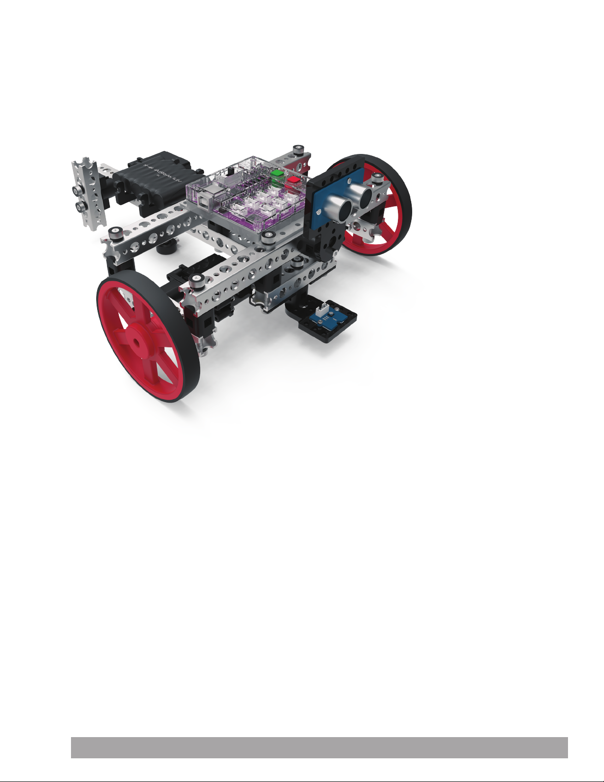
This is what you have been waiting for. It is time to move to the next level. You
have worked hard to learn the basics, and now it is time to apply them to an actual
robot. The next 10 activities will walk you through building, moving, navigating,
and adding sensors to a robot, and more, culminating in an activity that combines
everything. It’s about to get exciting!
Building and Coding the PULSE CodeeBot 45
Page 48
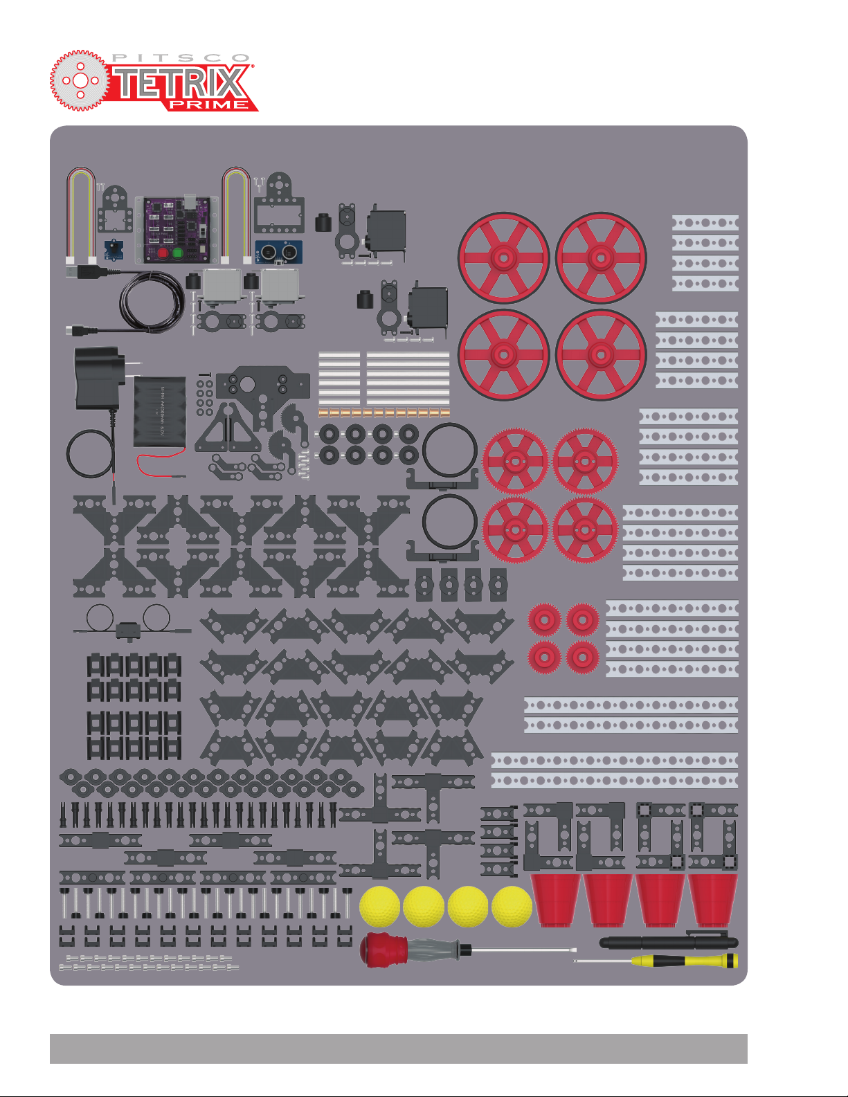
Programmable Robotics Set
Note: In order to complete the build shown in this book, you must have the TETRIX PRIME Programmable Set.
46 Building and Coding the PULSE CodeeBot
Page 49
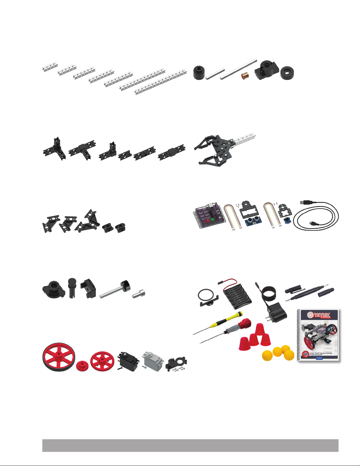
TETRIX PRIME Programmable Robotics Set
Parts Index
Beams
Part No. Part Name Quantity
40201 TETRIX PRIME 4-Hole Square Beam ..........................4
40202 TETRIX PRIME 5-Hole Square Beam ..........................4
40203 TETRIX PRIME 6-Hole Square Beam ..........................4
40204 TETRIX PRIME 7-Hole Square Beam ..........................4
40205 TETRIX PRIME 8-Hole Square Beam ..........................4
40206 TETRIX PRIME 13-Hole Square Beam .........................2
40207 TETRIX PRIME 15-Hole Square Beam .........................2
Internal Connectors
Part No. Part Name Quantity
40212 TETRIX PRIME 3-Way Beam Connector .......................4
40213 TETRIX PRIME Tee Beam Connector ..........................4
40211 TETRIX PRIME 90-Degree Beam Connector ..................4
40214 TETRIX PRIME Beam End Connector .........................4
40322 TETRIX PRIME Beam Extension Connector . . . . . . . . . . . . . . . . . . .4
40215 TETRIX PRIME Beam Straight Connector .....................4
External Connectors
Part No. Part Name Quantity
40208 TETRIX PRIME 90-Degree Beam Bracket ................... 10
40209 TETRIX PRIME 60-Degree Beam Bracket ....................10
40210 TETRIX PRIME Tee Beam Bracket ...........................10
40216 TETRIX PRIME Straight Block Beam Connector ............. 10
40217 TETRIX PRIME 90-Degree Cross Block Connector ..........10
Wheel, Gear, & Servo Hardware
Part No. Part Name Quantity
40230 TETRIX PRIME Shaft Servo Hub ...............................6
40225 TETRIX PRIME 80 mm Steel Axle .............................6
40226 TETRIX PRIME 40 mm Steel Axle .............................6
40227 TETRIX PRIME 8 mm x 6 mm Bronze Bushing .............. 12
40228 TETRIX PRIME Beam Attachment Hub .......................4
40229 TETRIX PRIME D-Shaft Set Collar .............................8
Gripper Assembly
Part No. Part Name Quantity
40234 TETRIX PRIME Gripper Kit ....................................1
Electronics & Control
Part No. Part Name Quantity
44268 TETRIX PULSE Robotics Controller with USB cable ...........1
43055 Ultrasonic Sensor Pack .......................................1
43056 Line Finder Sensor Pack ......................................1
Connecting Hardware
Part No. Part Name Quantity
40219 TETRIX PRIME Quick Rivet Connector ...................... 24
40220 TETRIX PRIME Quick Rivet Peg .............................24
40221 TETRIX PRIME Wing Nut ................................... 24
40323 TETRIX PRIME Thumbscrew ................................24
40516 Socket Head Cap Screw .................................... 25
Wheels, Gears, & Servos
Part No. Part Name Quantity
40222 TETRIX PRIME Wheel with Tire. . . . . . . . . . . . . . . . . . . . . . . . . . . . . . . .4
40223 TETRIX PRIME 40-Tooth Plastic Gear ..........................4
40224 TETRIX PRIME 80-Tooth Plastic Gear ..........................4
40538 HiTec HS322-HD Servo Motor ................................2
44298 TETRIX PRIME DC Motor .....................................2
40232 TETRIX PRIME Servo Mounting Bracket ......................6
Batteries & Hardware
Part No. Part Name Quantity
40236 TETRIX PRIME Battery Mount Bracket ........................2
40235 TETRIX PRIME 6 V NiMH Battery Pack ........................1
40378 TETRIX PRIME 5-Cell NiMH Battery Pack Charger .............1
36404 4-in-1 Screwdriver ...........................................1
40341 Miniature Ball-Point Hex Driver ..............................1
42991 2-in-1 Screwdriver ...........................................1
41769 Plastic 2 oz Cups .............................................4
14041 Practice Golf Balls ............................................4
44301 TETRIX PULSE Robotics Controller Programming Guide .....1
Building and Coding the PULSE CodeeBot 47
Page 50
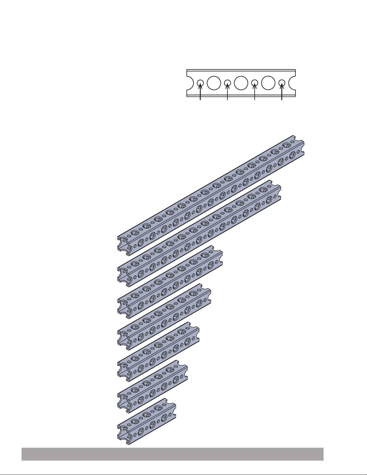
TETRIX PRIME Hardware Components
Beams
The beams are named by the number
of small holes on one side of the beam.
Do not select beams by counting
the larger holes (see right).
To identify TETRIX PRIME Square Beams, count the small holes. The
example above is a 4-hole square beam.
Structural Elements
1:1 scale
1 2 3 4
15-Hole Square Beam 40207
13-Hole Square Beam 40206
8-Hole Square Beam 40205
7-Hole Square Beam 40204
6-Hole Square Beam 40203
5-Hole Square Beam 40202
4-Hole Square Beam 40201
48 Building and Coding the PULSE CodeeBot
Page 51
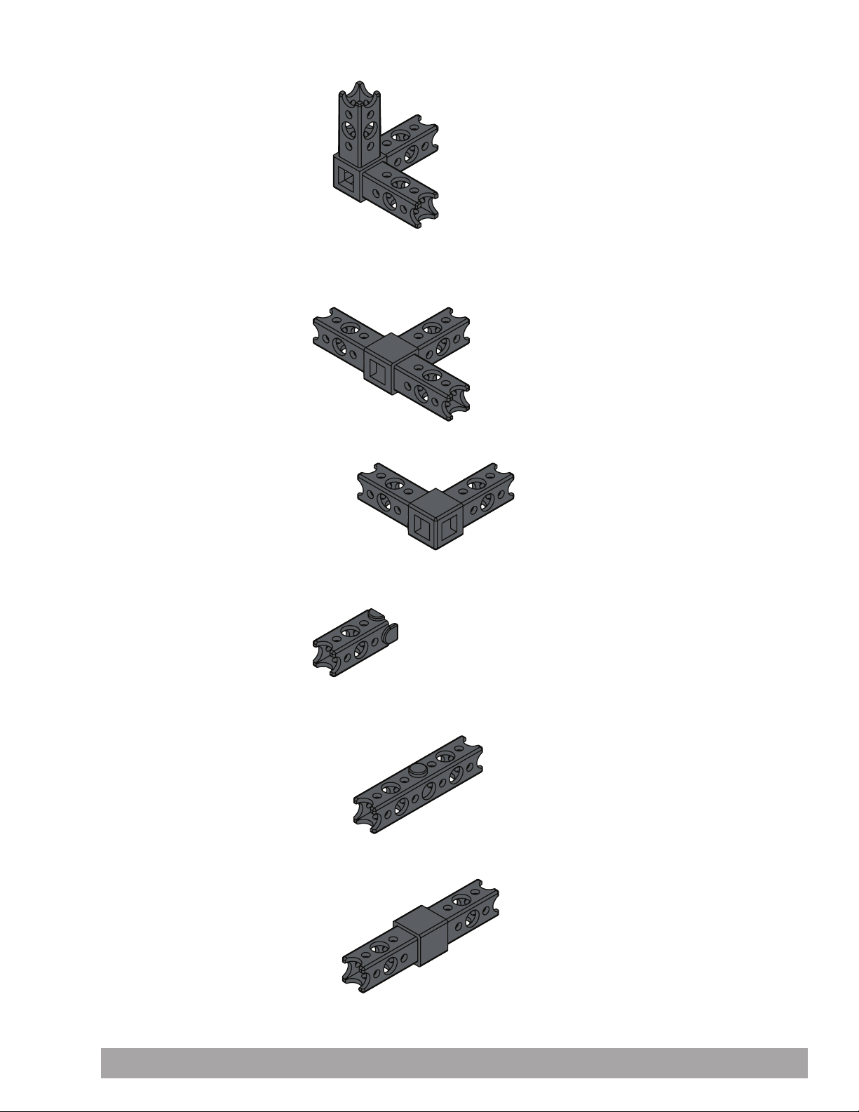
Structural Elements
3-Way Beam Connector 40212
Tee Beam Connector 40213
90-Degree Beam Connector 40211
Beam End Connector 40214
Beam Extension Connector 40322
Beam Straight Connector 40215
Building and Coding the PULSE CodeeBot 49
Page 52
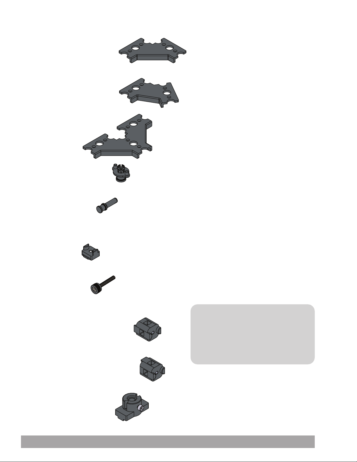
Structural Elements
90-Degree Beam Bracket 40208
60-Degree Beam Bracket 40209
Tee Beam Bracket 40210
Quick Rivet Connector 40219
Quick Rivet Peg 40220
Wing Nut 40221
Thumbscrew 40323
Straight Block Beam Connector 40216
90-Degree Cross Block Connector 40217
TIP: These two parts, the straight block
beam connector and the 90-degree cross
block connector, are very close in appearance
and can be easily confused. Please doublecheck that you are using the one the
directions call for.
Beam Attachment Hub 40228
50 Building and Coding the PULSE CodeeBot
Page 53
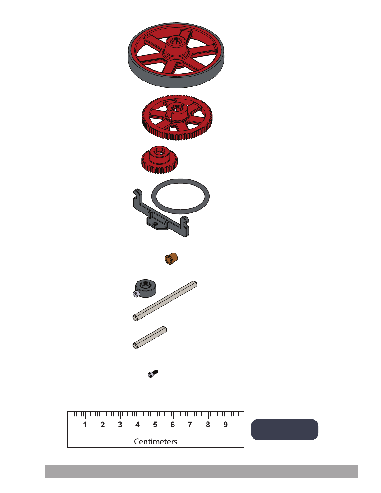
Motion Elements
Wheel with Tire 40222
80-Tooth Plastic Gear 40224
40-Tooth Plastic Gear 40223
Battery Mount Bracket 40236
8 mm x 6 mm Bronze Bushing 40227
D-Shaft Set Collar 40229
80 mm Steel Axle 40225
40 mm Steel Axle 40226
Socket Head Cap Screw 40516
Measure 80 mm and 40 mm steel axles here.
Building and Coding the PULSE CodeeBot 51
Note: 10 mm = 1 cm
Page 54
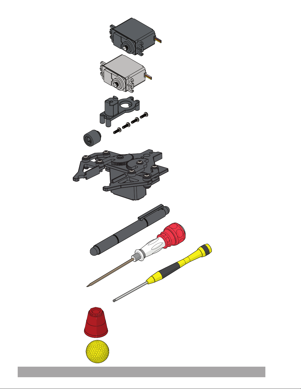
Motion Elements
HiTec HS322-HD Servo Motor 40538
TETRIX PRIME DC Motor 44298
Servo Mounting Bracket 40232
Shaft Servo Hub 40230
Gripper Kit 40234
Power, Tools, and Accessories Elements
4-in-1 Screwdriver 36404
2-in-1 Screwdriver 42991
Miniature Ball-Point Hex Driver 40341
Plastic 2 oz Cups 41769
Practice Golf Balls 14041
52 Building and Coding the PULSE CodeeBot
Page 55
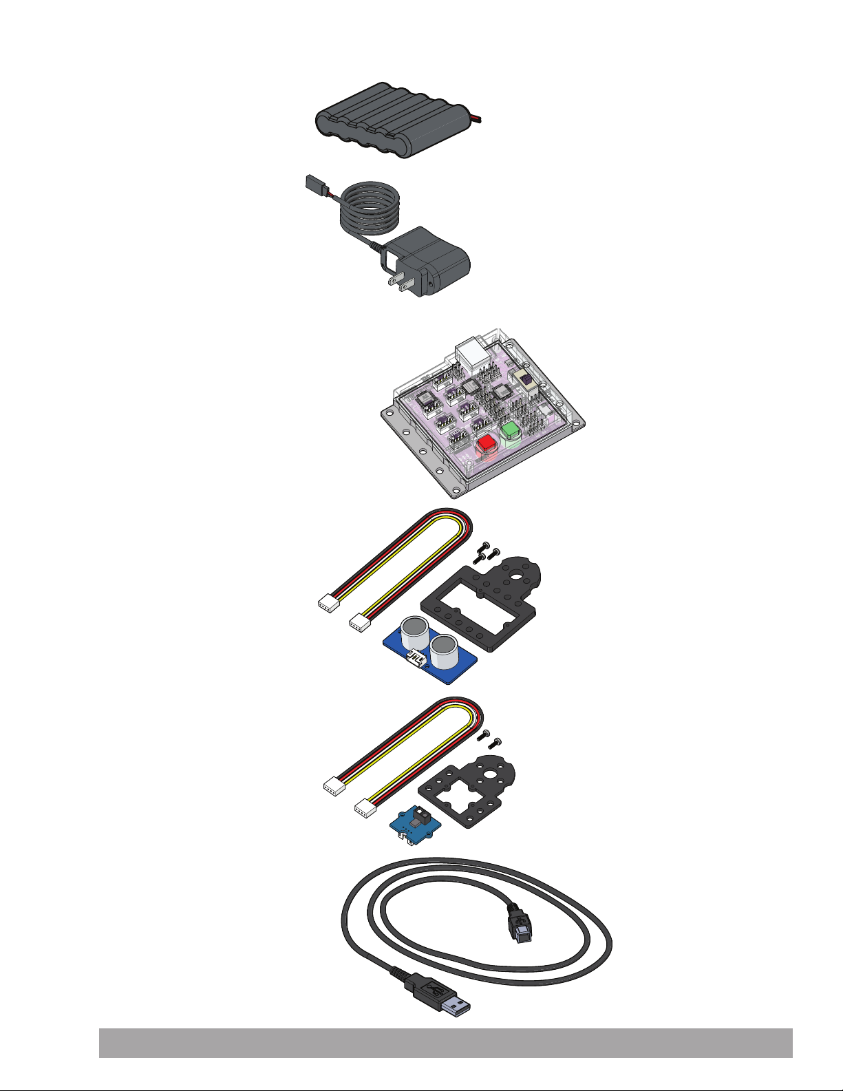
Power, Tools, and Accessories Elements
6 V NiMH Battery Pack 40235
5-Cell NiMH Battery Pack Charger 40378
Control Elements
TETRIX PULSE Robotics Controller 44268
Ultrasonic Sensor Pack 43055
Line Finder Sensor Pack 43056
3-Foot Type A-B USB Cable 40967
Building and Coding the PULSE CodeeBot 53
Page 56
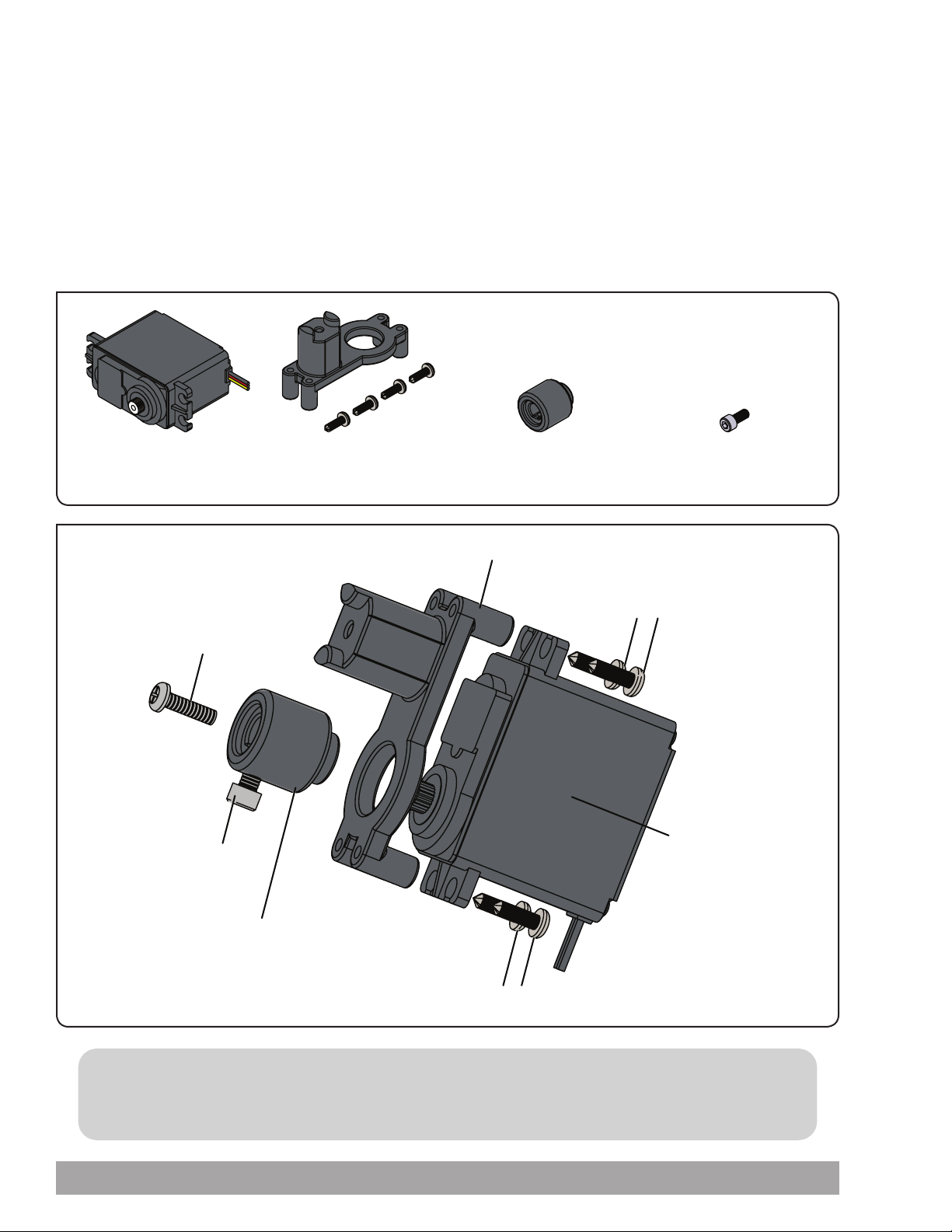
Standard Servo Assembly
You will need the HiTec HS322-HD Servo Motor with screw, the servo mounting bracket with screws, a shaft servo hub, and
a socket head cap screw. You will also need the 4-in-1 screwdriver and the miniature ball-point hex driver. remove the white
plastic servo horn attached to the servo. Retain the screw for future use, but discard the white plastic servo horn. Attach the
Standard Servo label to the servo. Assemble one of the standard servos as indicated in the illustrations. The other standard
servo will be used for the gripper assembly.
Standard servo motors are used for proportional rotation and for grippers, steering, and positioning.
Parts Needed
1x
HiTec HS322-HD
Servo Motor 40538
Servo Horn Screw
Socket Head Cap Screw
1x
Servo Mounting
Bracket 40232
Servo Mounting Bracket
1x
Shaft Servo Hub
40230
Self-Tapping Screw
1x
Socket Head Cap
Screw 40516
HiTec HS322-HD Servo
Motor
Shaft Servo Hub
Self-Tapping Screw
TIP: Keep in mind that the continuous rotation servo mounts in the servo mounting bracket the same
way as the standard servo, but there is no need to center the servo horn.
54 Building and Coding the PULSE CodeeBot
Page 57
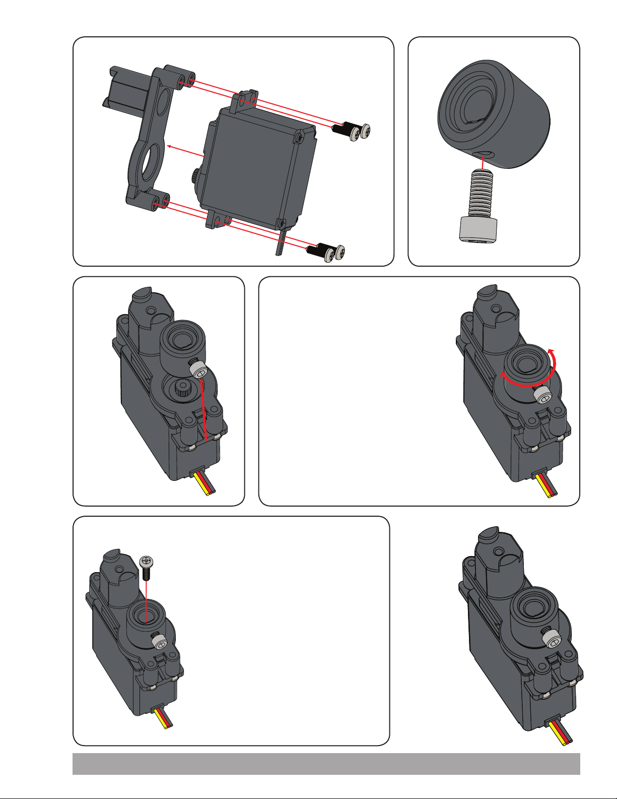
Step 1
Step 2
Step 3
Step 5
Step 4
Before attaching the servo hub, you
must make sure the servo is in the
neutral position. To do this, connect
both the servo and the battery to
the receiver and turn on the power
to the remote transmitter. Make sure
both joysticks and trimmers are in the
center, or neutral, position. The servo
motor will move to its neutral position.
Line up the splines on the hub with the
splines on the servo and press the two parts
together. The set screw should line up as
close as possible with the center of the servo
case. Tighten the screw holding the hub in
place.
Finished
Assembly
Using the remote transmitter, verify the
operation of the servo. If the servo operates
properly, disconnect the battery from the
receiver and the servo. Your servos are ready
for use.
Building and Coding the PULSE CodeeBot 55
Page 58
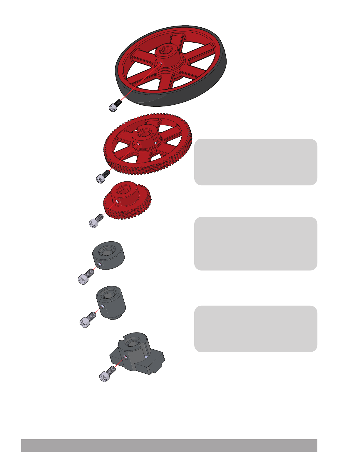
Set Screw Applications
Wheel with Tire 40222
80-Tooth Plastic Gear 40224
40-Tooth Plastic Gear 40223
D-Shaft Set Collar 40229
Shaft Servo Hub 40230
TIP: Please keep in mind that if your
parts already have socket head cap screws
installed and the directions call for that
operation, you can skip to the next step.
TIP: Directions will show these types of
parts in proper position. After the parts are
in place, don’t forget to tighten the socket
head cap screws before moving on to the
next step.
Beam Attachment Hub 40228
56 Building and Coding the PULSE CodeeBot
TIP: Socket head cap screws should be
snug but not overtightened. overtightening
socket head cap screws can damage
components.
Page 59
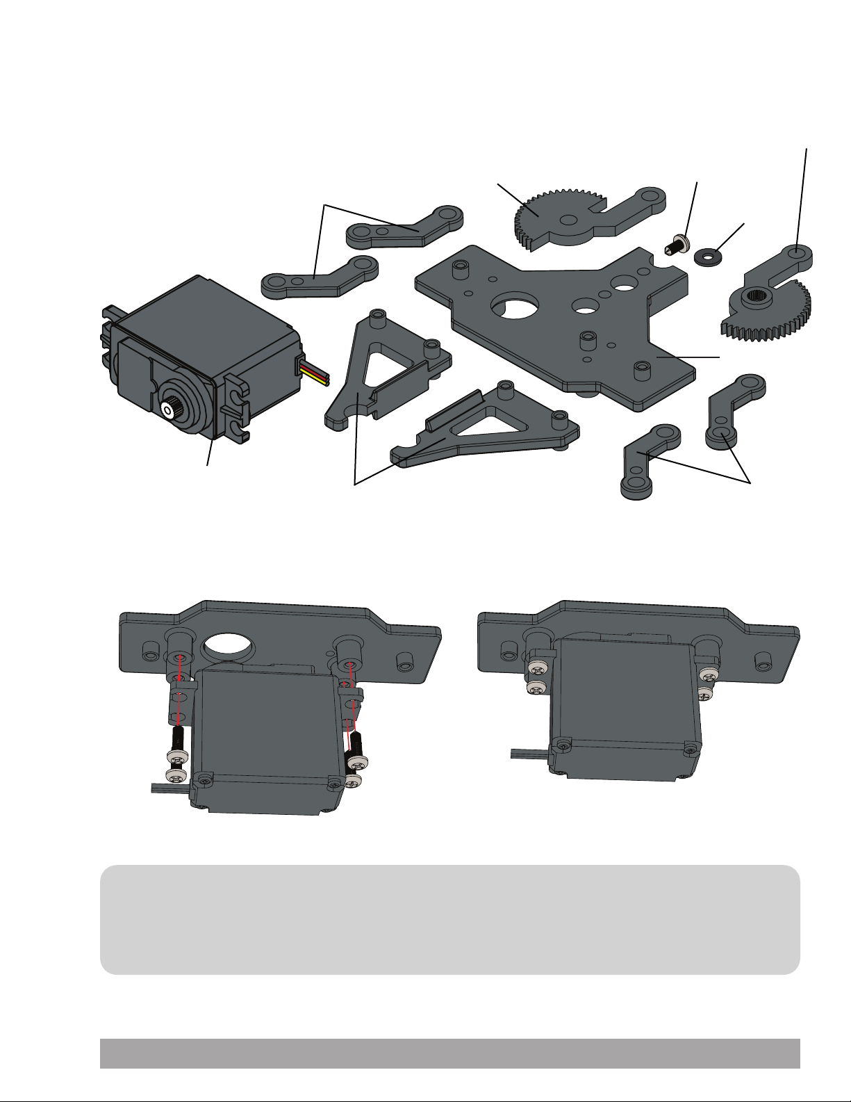
Gripper Assembly
The gripper kit is included with the TETRIX PRIME Programmable Robotics Set
but is shown here for reference.
Left Gripper
Gear Arm
Gripper Pivot Arm
11x
Self-Tapping
Screw
Pivot Washer
Right Gripper
Gear Arm
12x
Gripper Plate
Standard Servo
Gripper Pincer
Step 1 Step 2
Gripper Pivot Arm
IMPORTANT: Before attaching the right gripper gear arm to the standard servo, attach the standard
servo to the gripper plate. Then, connect the standard servo and position the servo motor to the neutral position for
proper gear position alignment as shown in the following steps. Instructions on assembly of TETRIX PRIME parts can
also be found at TETRIXrobotics.com.
Building and Coding the PULSE CodeeBot 57
Page 60
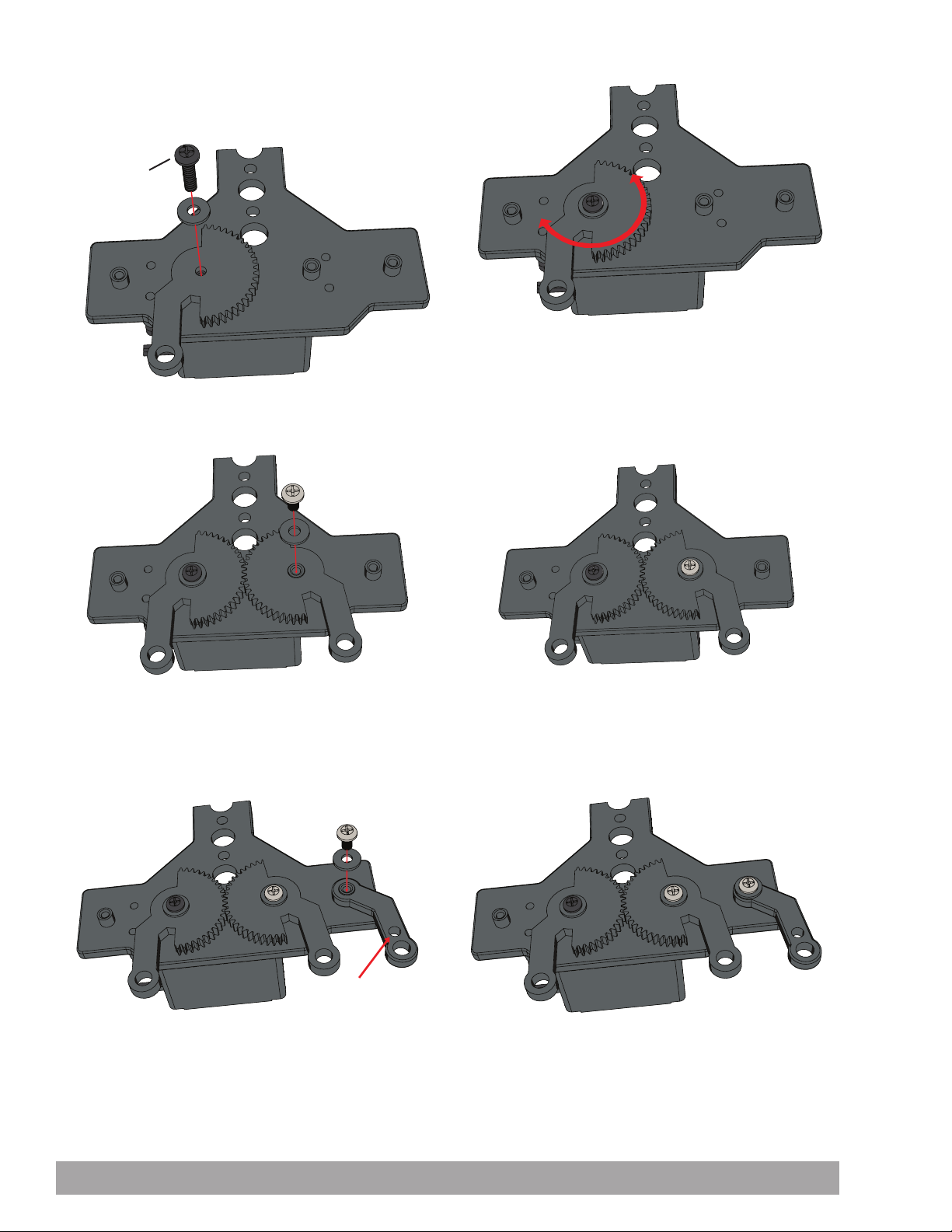
Step 3 Step 4
Servo Horn
Screw
Step 5 Step 6
Step 7 Step 8
58 Building and Coding the PULSE CodeeBot
Page 61
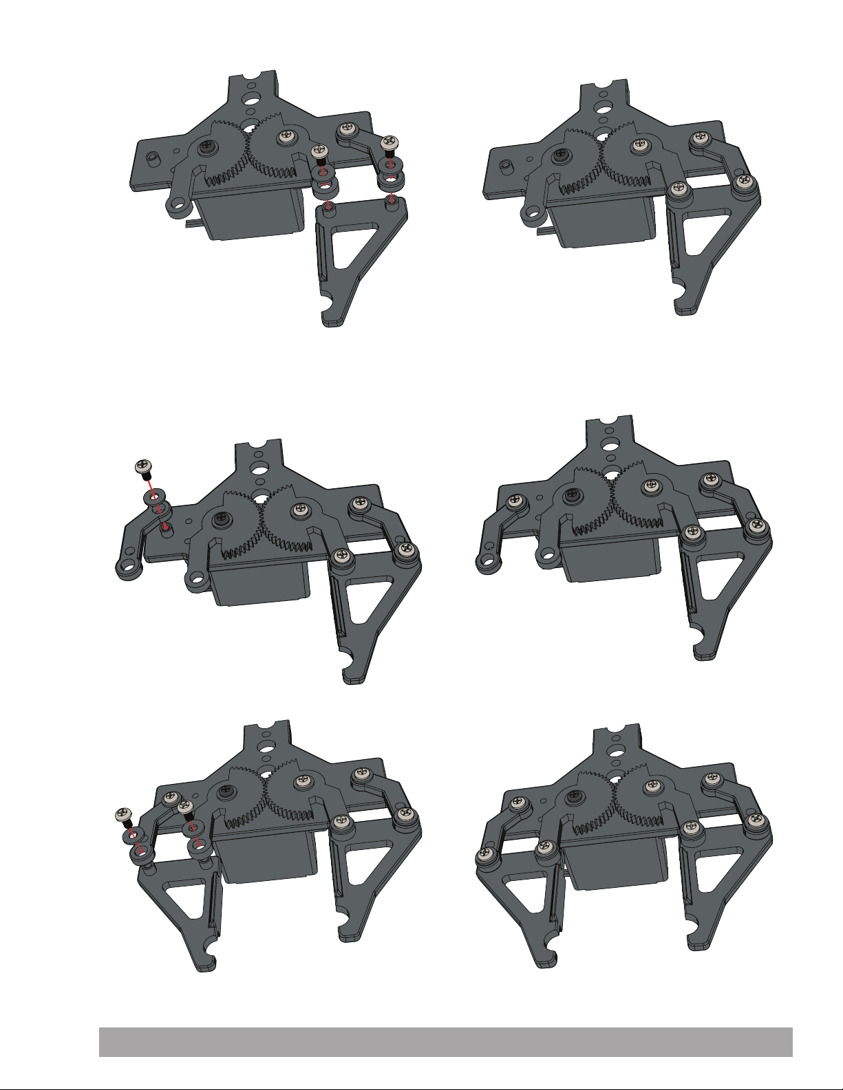
Step 9 Step 10
Step 11
Step 13
Step 12
Step 14
Building and Coding the PULSE CodeeBot 59
Page 62
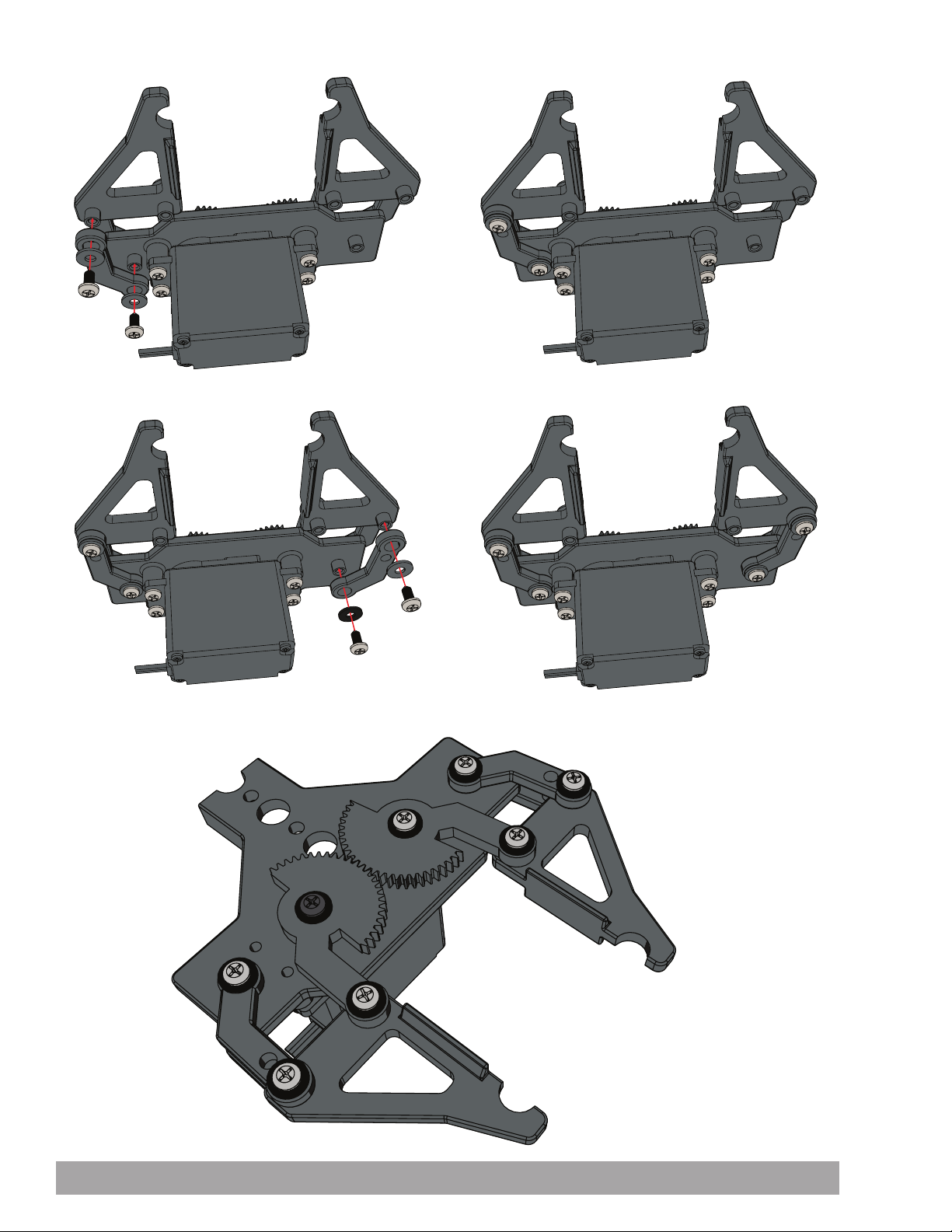
Step 16Step 15
Step 18Step 17
Finished Assembly
60 Building and Coding the PULSE CodeeBot
Page 63
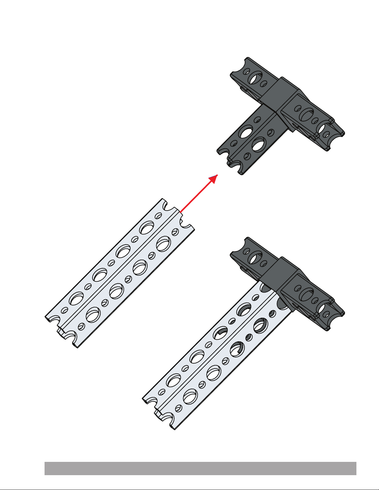
Construction Tips
Connectors fit inside beams and come in 3-way, tee, 90-degree, end, extension, and straight beam block connector designs.
Building and Coding the PULSE CodeeBot 61
Page 64
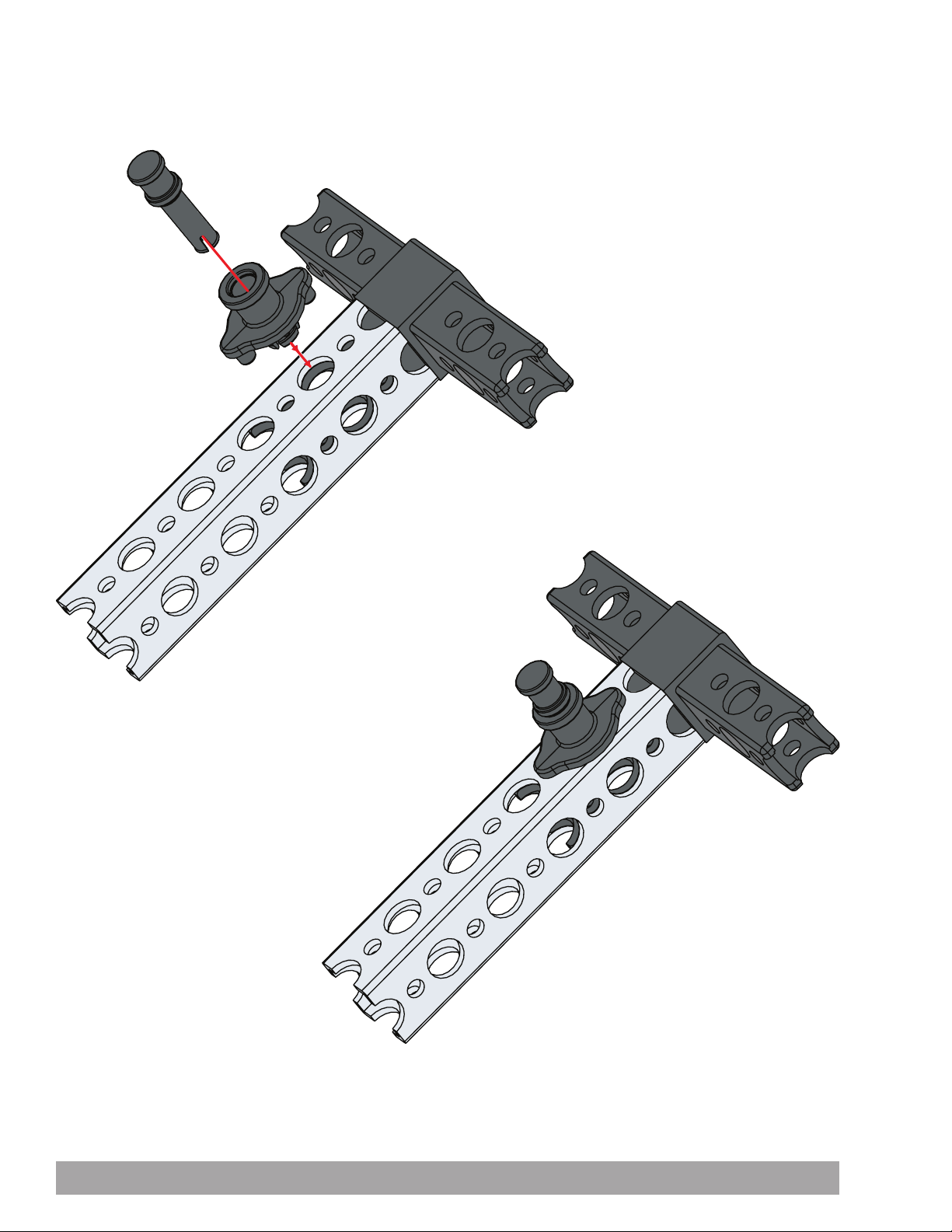
Quick rivet connectors and pegs are a quick option for securing connectors. Press the rivet in place on the beam and use
the peg to spread the rivet to secure the connection. Using rivets on two sides of the connection will make it more stable.
62 Building and Coding the PULSE CodeeBot
Page 65
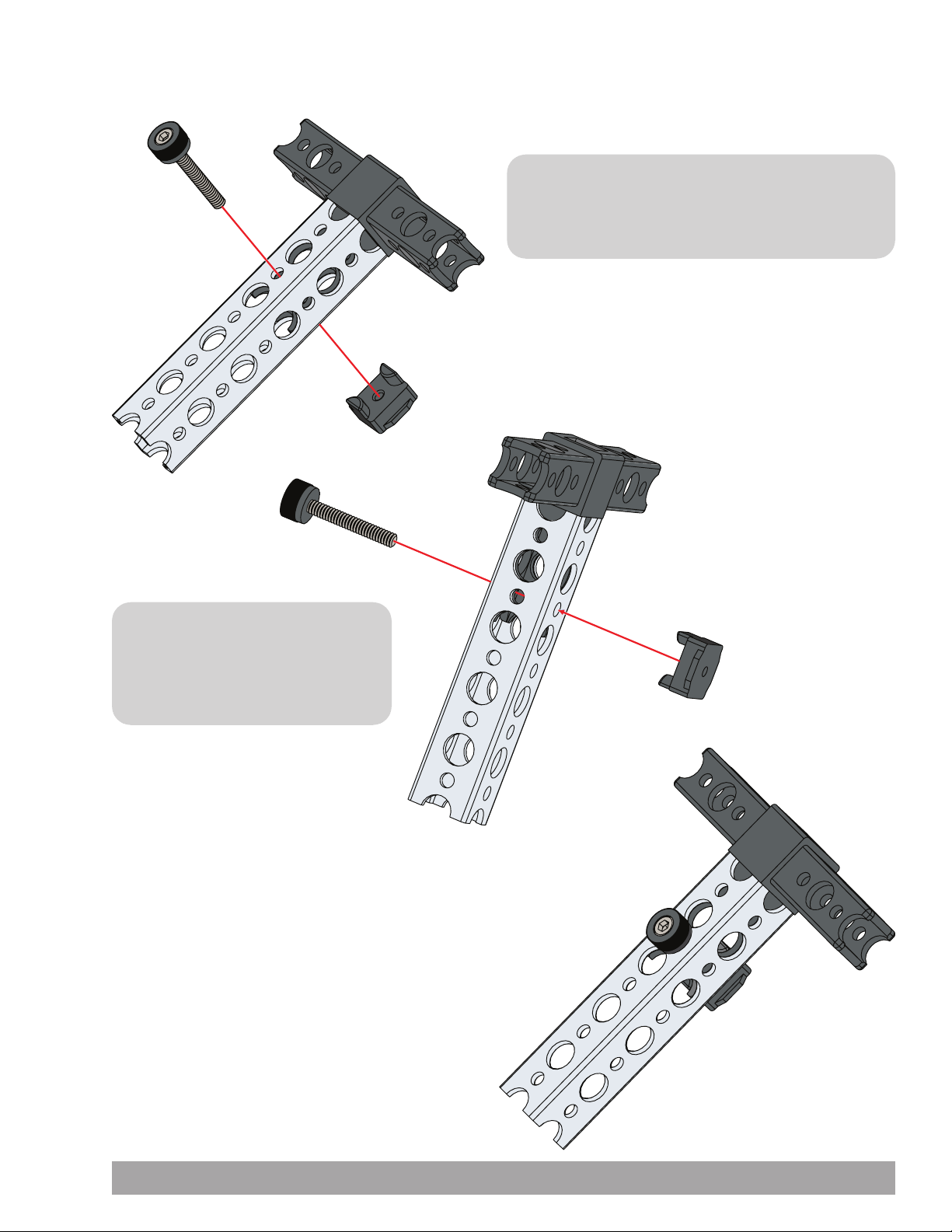
Joints can be made more permanent by using a thumbscrew and wing nut to secure the beams and connectors.
TIP: Wing nuts are placed in position first and
thumbscrews are tightened into them. After wing nuts
are placed and seated properly, they cannot be turned.
TIP: Thumbscrews should
be snug but not overtightened.
Overtightening thumbscrews can
damage components.
Building and Coding the PULSE CodeeBot 63
Page 66
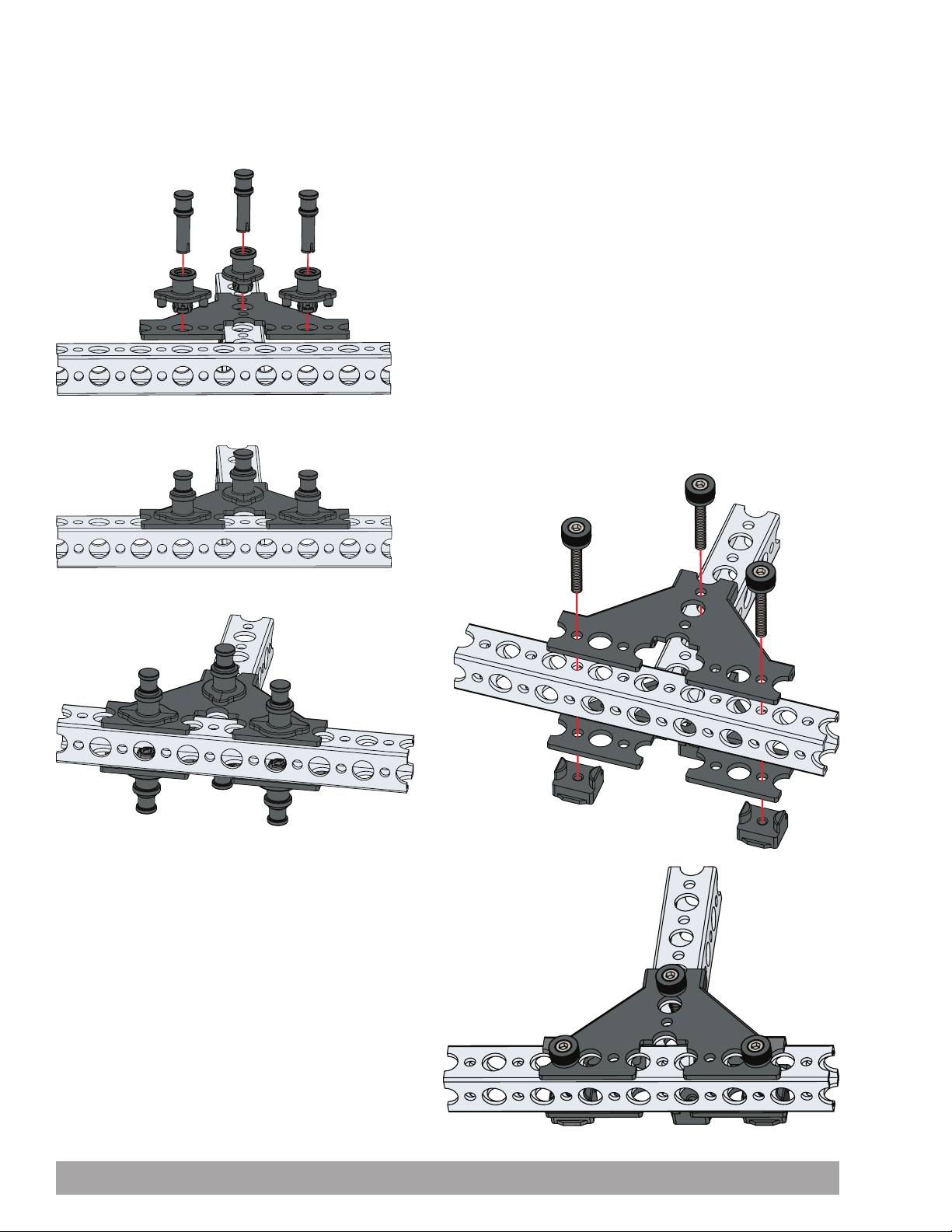
Brackets can also be used to connect beams. Brackets are available for a tee connection, 60-degree connection, or
90-degree connection. Brackets should be used in pairs, with two brackets on opposite sides of a beam. Brackets are
secured using quick rivets and pegs or thumbscrews and wing nuts.
64 Building and Coding the PULSE CodeeBot
Page 67
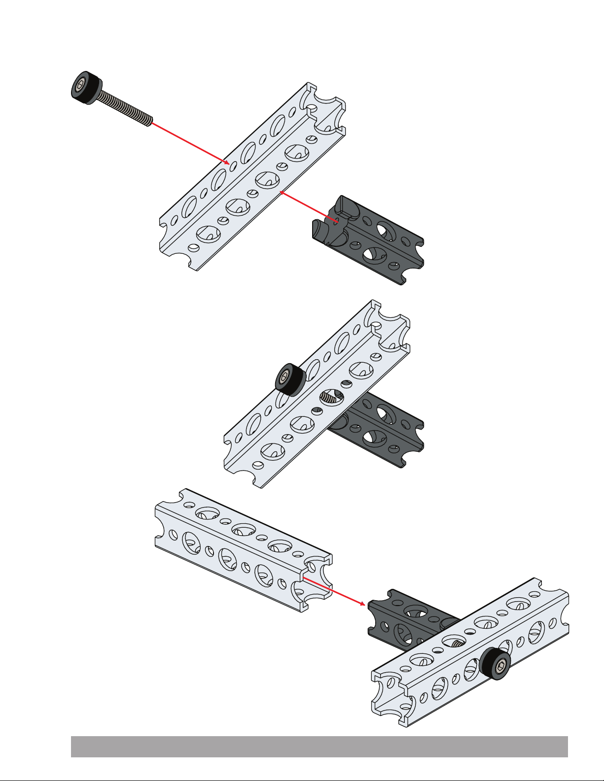
Beam end connectors, straight block beam connectors, and 90-degree cross block connectors are secured using a
thumbscrew through the beam and into the connector.
Building and Coding the PULSE CodeeBot 65
Page 68
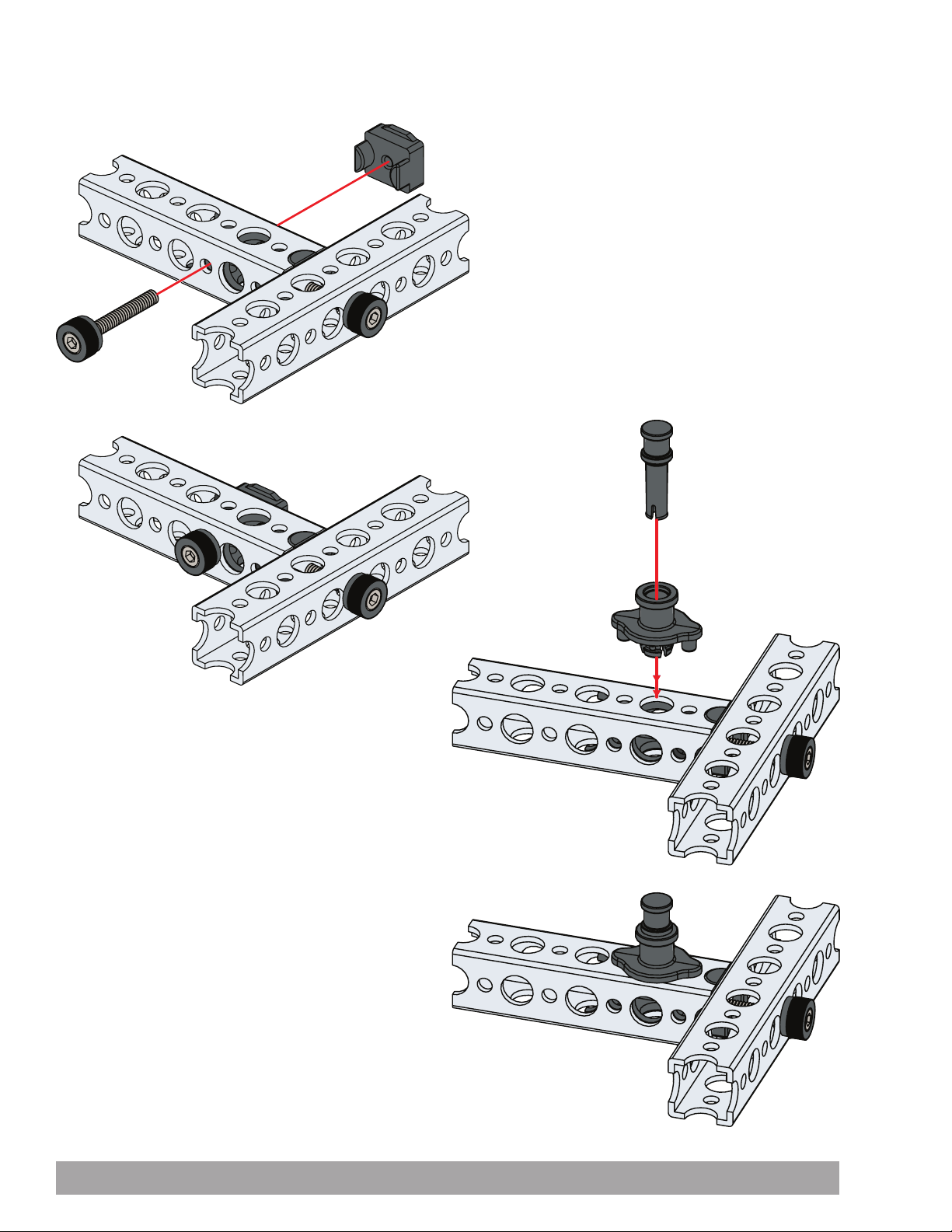
After the thumbscrew is used to secure the end of the connector, a quick rivet and peg or a thumbscrew and wing nut are
used to secure the intersecting beam.
66 Building and Coding the PULSE CodeeBot
Page 69
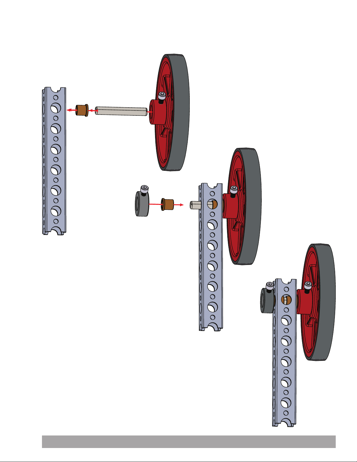
Anytime an axle is used, it should be supported at two points. Place a bronze bushing on opposite sides of a beam and
place the axle through the bushings. Secure the axle to a D-shaft set collar, wheel, gear, or hub.
Building and Coding the PULSE CodeeBot 67
Page 70
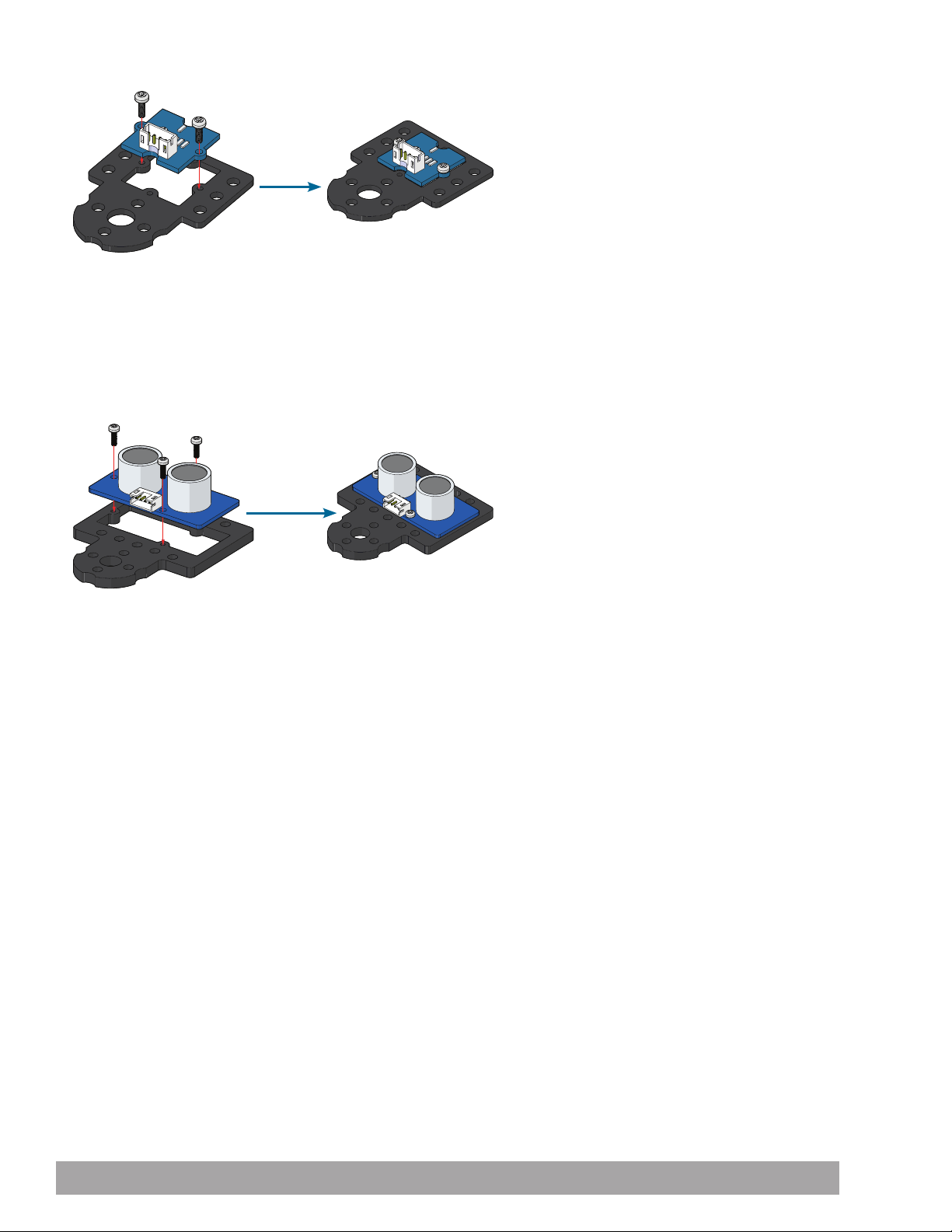
Line Finder Sensor Pack Assembly
The screws in this pack will self-thread into the plastic mounts. The
4-in-1 screwdriver that comes as part of the TETRIX robotics sets can
be used to install the screws. Take care not to overtighten the screws
upon installation or the plastic mount might be damaged.
Ultrasonic Sensor Pack Assembly
The screws in this pack will self-thread into the plastic mounts. The
4-in-1 screwdriver that comes as part of the TETRIX robotics sets can be
used to install the screws. Take care not to overtighten the screws upon
installation or the plastic mount might be damaged.
68 Building and Coding the PULSE CodeeBot
Page 71
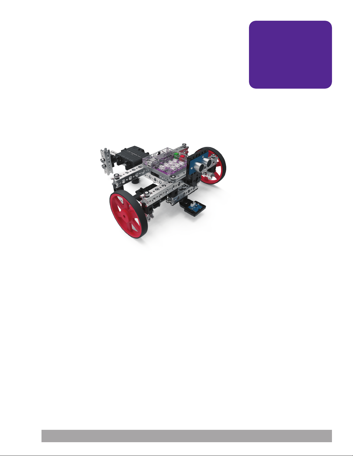
Activity 6: Build the PULSE Codee Bot
Introduction
You need a robot. Because the focus of this guide is on working with PULSE and
the TETRIX Ardublockly software, you do not need a complicated robot. With that in
mind, you will create the PULSE Codee Bot. The Codee Bot is meant to be simple,
easy to build, and exactly what you need for the purposes of this guide without any
unnecessary parts.
That being said, everything you learn with this basic bot can be transferred to a
more complicated bot as you continue on your robotics journey. The Codee Bot
uses two DC motors and PRIME wheels mounted on either side to make a perfect
test vehicle for your work with PULSE.
You will start with a basic drive frame and add more to it in later activities. You
can complete this build even if you have little to no experience with metal-based
building systems.
Building Time Expectations
30 minutes
Teacher Note: Other factors
can affect building time,
including matters such as set
organization and whether
the builder has a partner.
The building time is only an
estimate. Actual time might
vary.
Real-World Link
In manufacturing and assembly, it’s important to be able to follow instructions
exactly. Try making a piece of furniture without following the instructions and it will
likely have to be redone. Being able to follow a detailed procedure of steps is an
important skill that is used in a multitude of real-life applications.
Careers: machine operator, roboticist, engineer
STEM Connections
• Science
Ĕ Wheel and axle
Ĕ Screw
• Technology
Ĕ Materials
Ĕ Fasteners
• Engineering
Ĕ Machine design
Ĕ Construction
• Math
Ĕ Length
Ĕ Diameter
Building and Coding the PULSE CodeeBot 69
Page 72
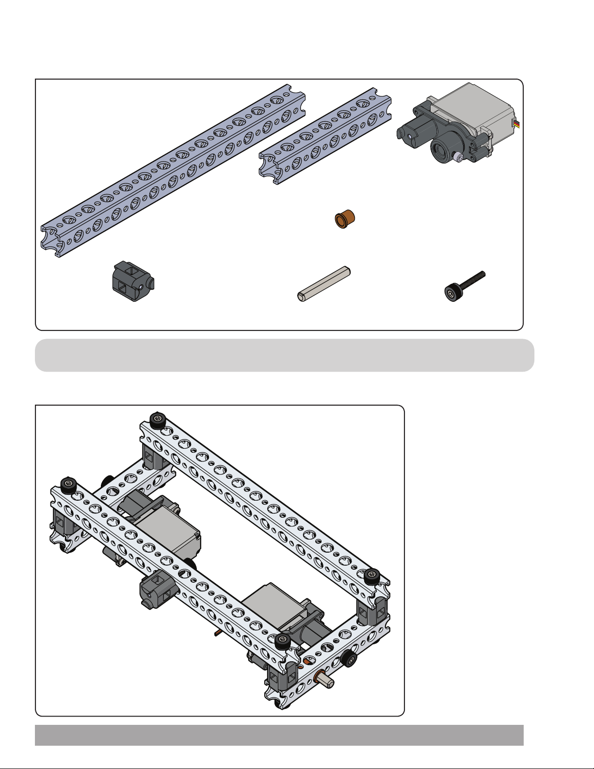
Step 1
Parts Needed
2x
6-Hole Square Beam 40203
2x
13-Hole Square Beam 40206
8 mm x 6 mm Bronze Bushing 40227
5x
90-Degree Cross Block Connector 40217
Tip: See page 48 for help with identifying beam elements. To identify TETRIX PRIME square beams, count the small holes.
40 mm Steel Axle 40226
4x
2x
TETRIX DC Motor 44298
with Servo Mounting
Bracket 40232 (Assembly
instructions on pages
Thumbscrew 40323
2x
54-55)
11x
Partial assembly should look like this.
70 Building and Coding the PULSE CodeeBot
Page 73

Step 1.0
Build two like this.
Step 1.1
Building and Coding the PULSE CodeeBot 71
Page 74
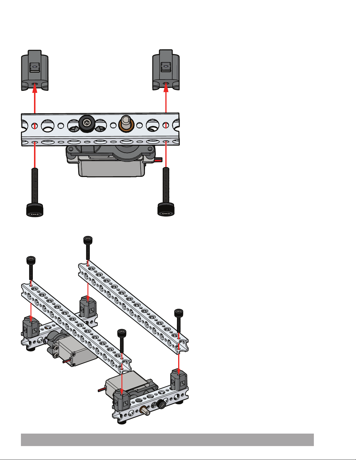
Step 1.2
Step 1.3
72 Building and Coding the PULSE CodeeBot
Page 75
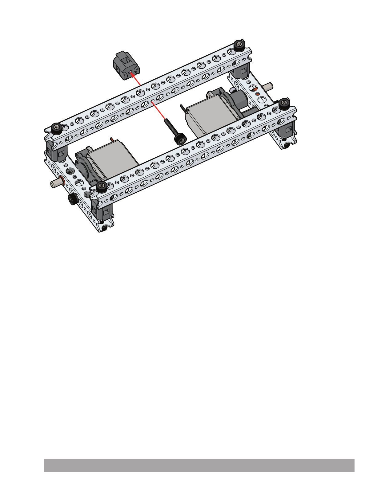
Step 1.4
Building and Coding the PULSE CodeeBot 73
Page 76
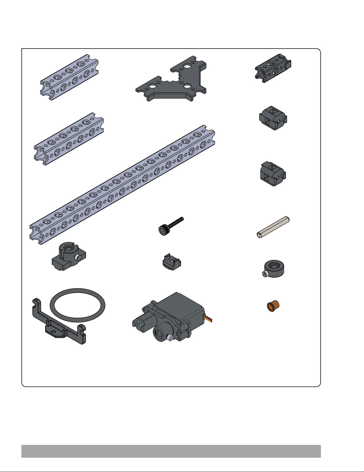
Step 2
Parts Needed
1x
4-Hole Square Beam 40201
1x
5-Hole Square Beam 40202
Tee Beam Bracket 40210
1x
15-Hole Square
Beam 40207
1x
Beam End Connector 40214
1x
2x
Straight Block Beam Connector
40216
2x
90-Degree Cross Block Connector
40217
2x
Beam Attachment Hub 40228
2x
Battery Mount Bracket 40236
10x
Thumbscrew 40323
1x
Wing Nut 40221
1x
HiTec HS322-HD Servo Motor
40538 with Servo Mounting
Bracket 40232 (Assembly
instructions on pages 54-55)
2x
40 mm Steel Axle 40226
1x
D-Shaft Set Collar 40229
2x
8 mm x 6 mm Bronze Bushing
40227
74 Building and Coding the PULSE CodeeBot
Page 77
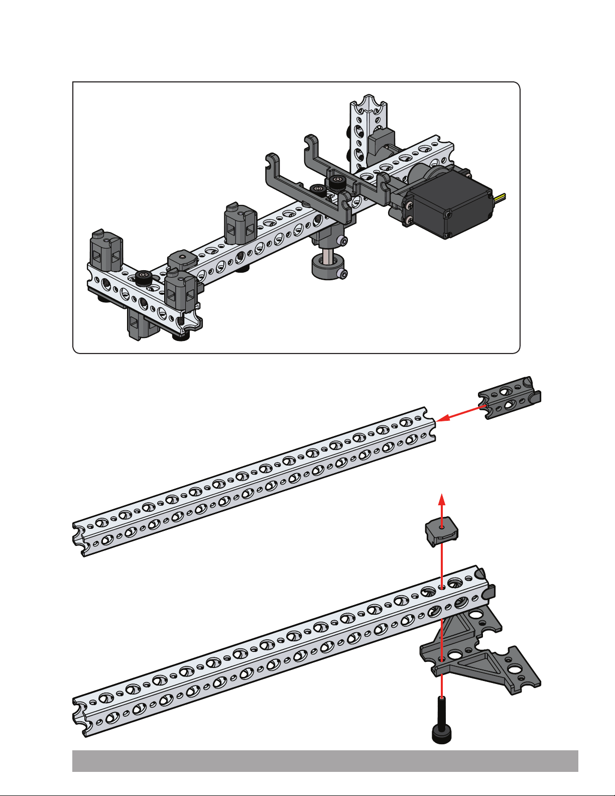
Partial assembly should look like this.
Step 2.0
Step 2.1
Building and Coding the PULSE CodeeBot 75
Page 78
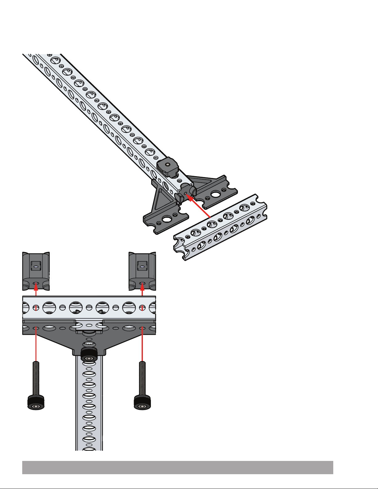
Step 2.2
Step 2.3
76 Building and Coding the PULSE CodeeBot
Page 79
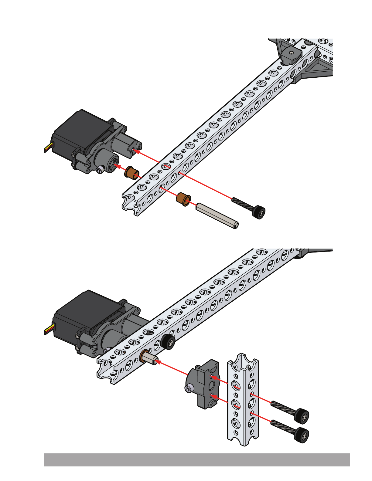
Step 2.4
Step 2.5
Building and Coding the PULSE CodeeBot 77
Page 80
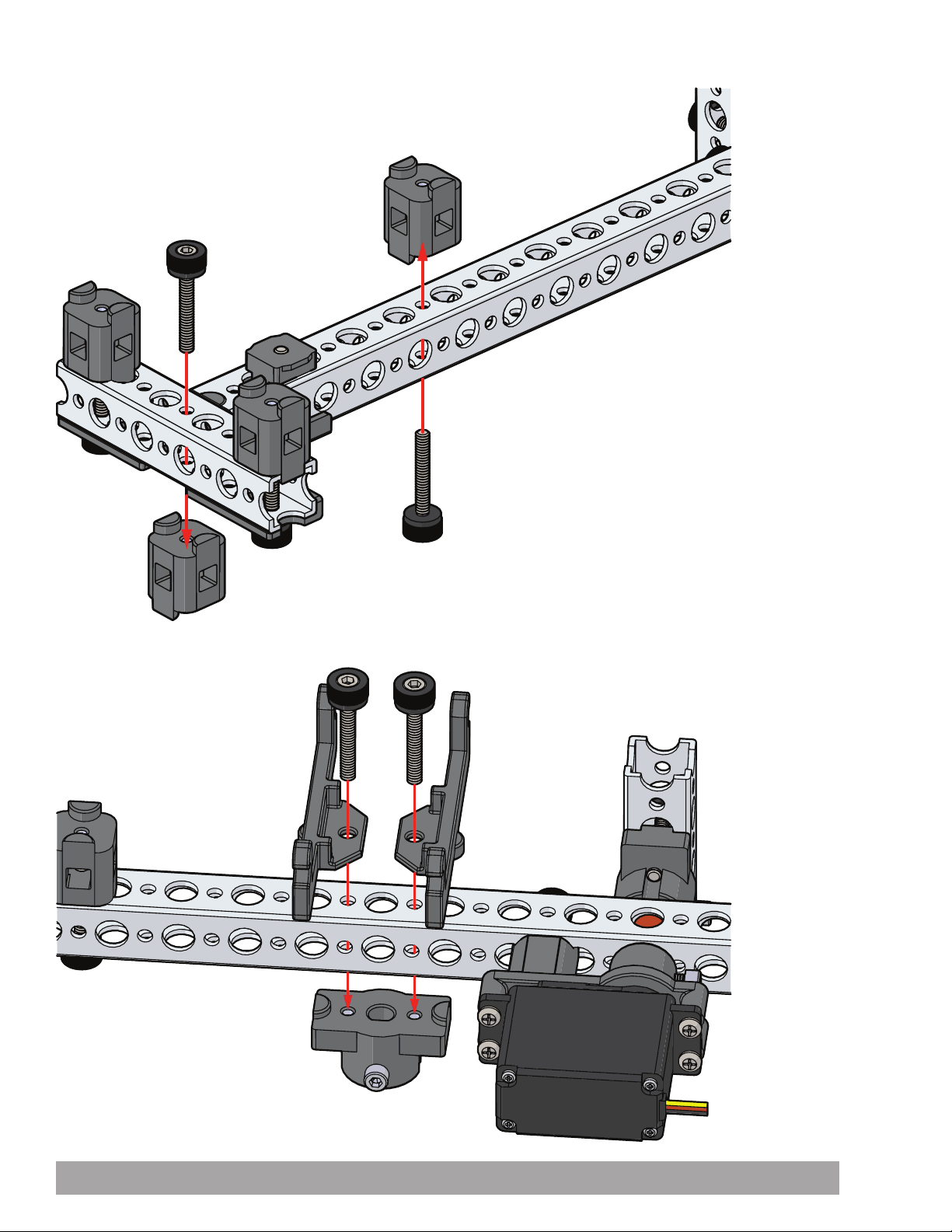
Step 2.6
Step 2.7
78 Building and Coding the PULSE CodeeBot
Page 81
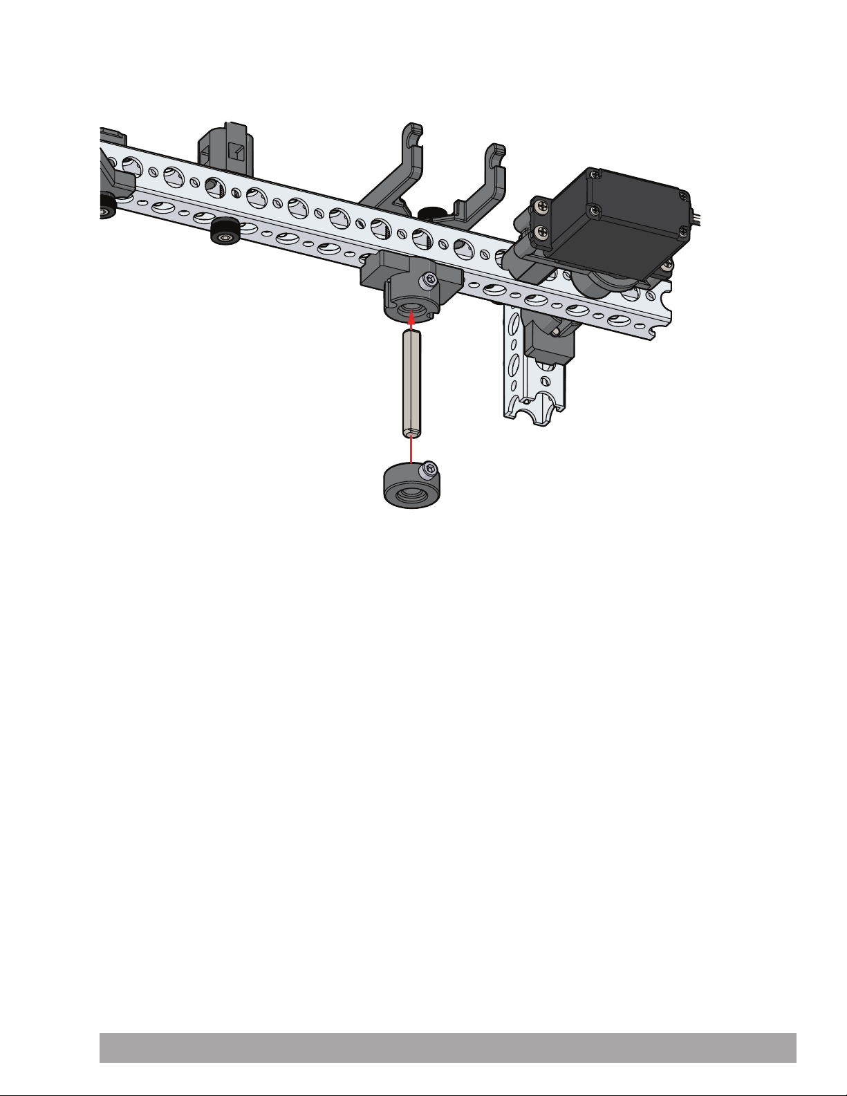
Step 2.8
Building and Coding the PULSE CodeeBot 79
Page 82
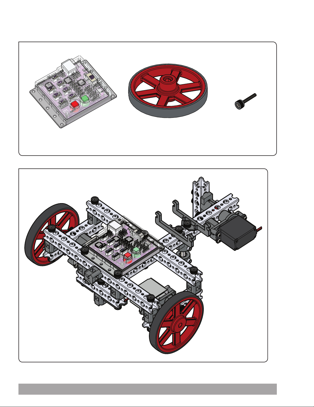
Step 3
Parts Needed
1x
TETRIX® PULSE™ Controller 44268
Partial assembly should look like this.
2x
Wheel with Tire 40222
3x
Thumbscrew 40323
80 Building and Coding the PULSE CodeeBot
Page 83
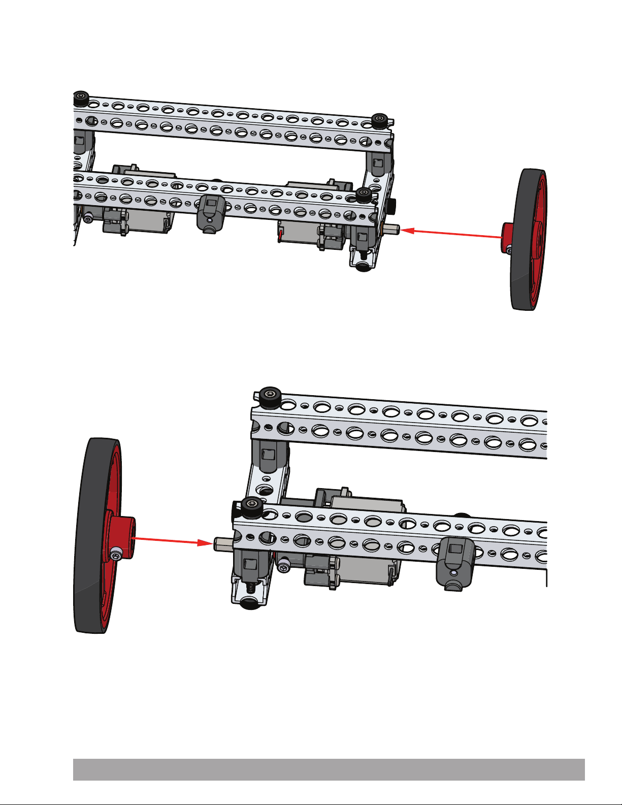
Step 3.0
Step 3.1
Building and Coding the PULSE CodeeBot 81
Page 84
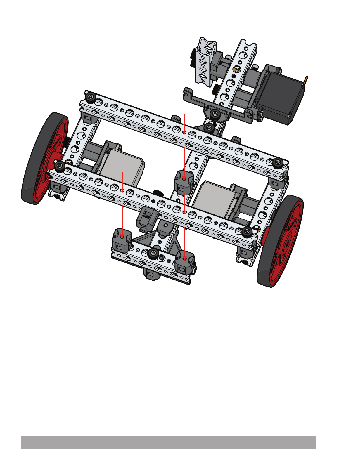
Step 3.2
82 Building and Coding the PULSE CodeeBot
Page 85
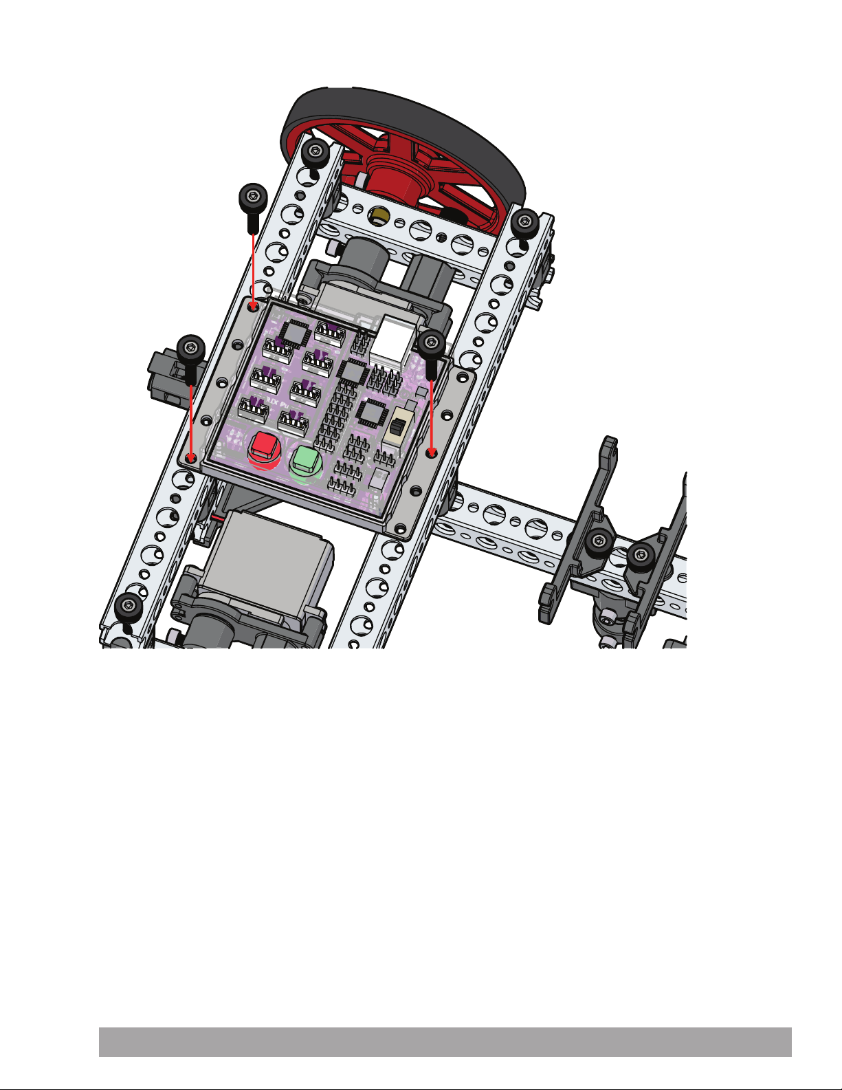
Step 3.3
Building and Coding the PULSE CodeeBot 83
Page 86
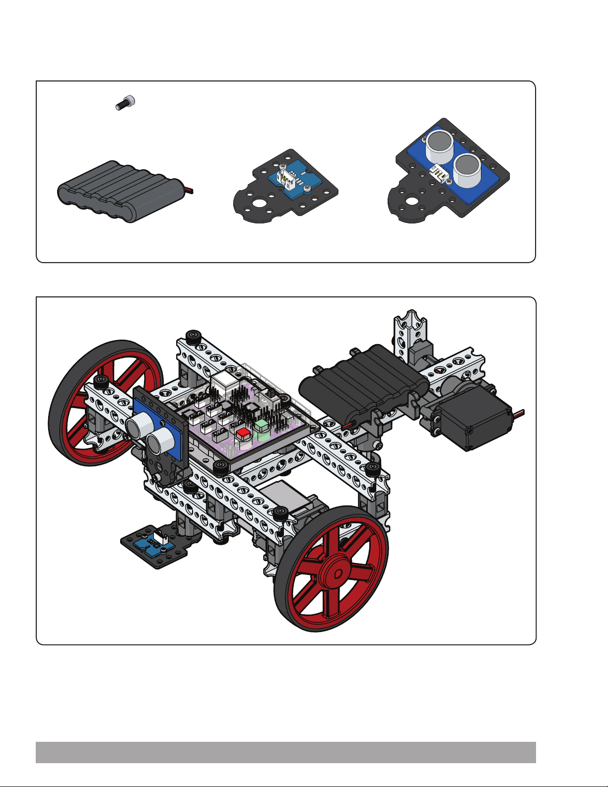
Step 4
Parts Needed
2x
Socket Head Cap Screw 40516
1x
6 V NiMH Battery Pack 40235
Partial assembly should look like this.
Line Finder Sensor Pack 43056
1x
1x
Ultrasonic Sensor Pack 43055
84 Building and Coding the PULSE CodeeBot
Page 87
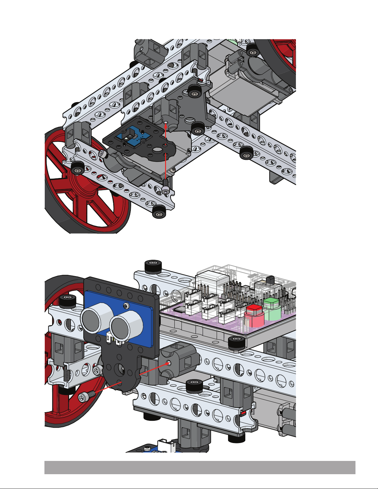
Step 4.0
Step 4.1
Building and Coding the PULSE CodeeBot 85
Page 88
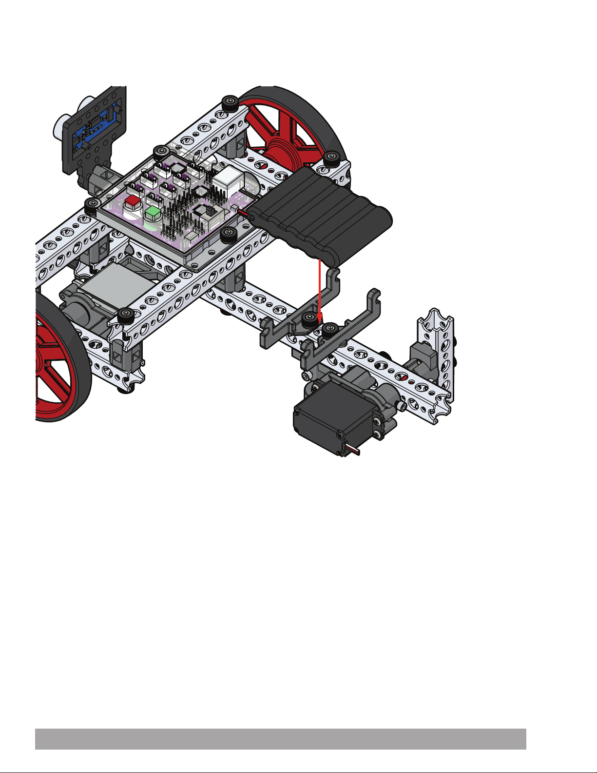
Step 4.2
86 Building and Coding the PULSE CodeeBot
Page 89
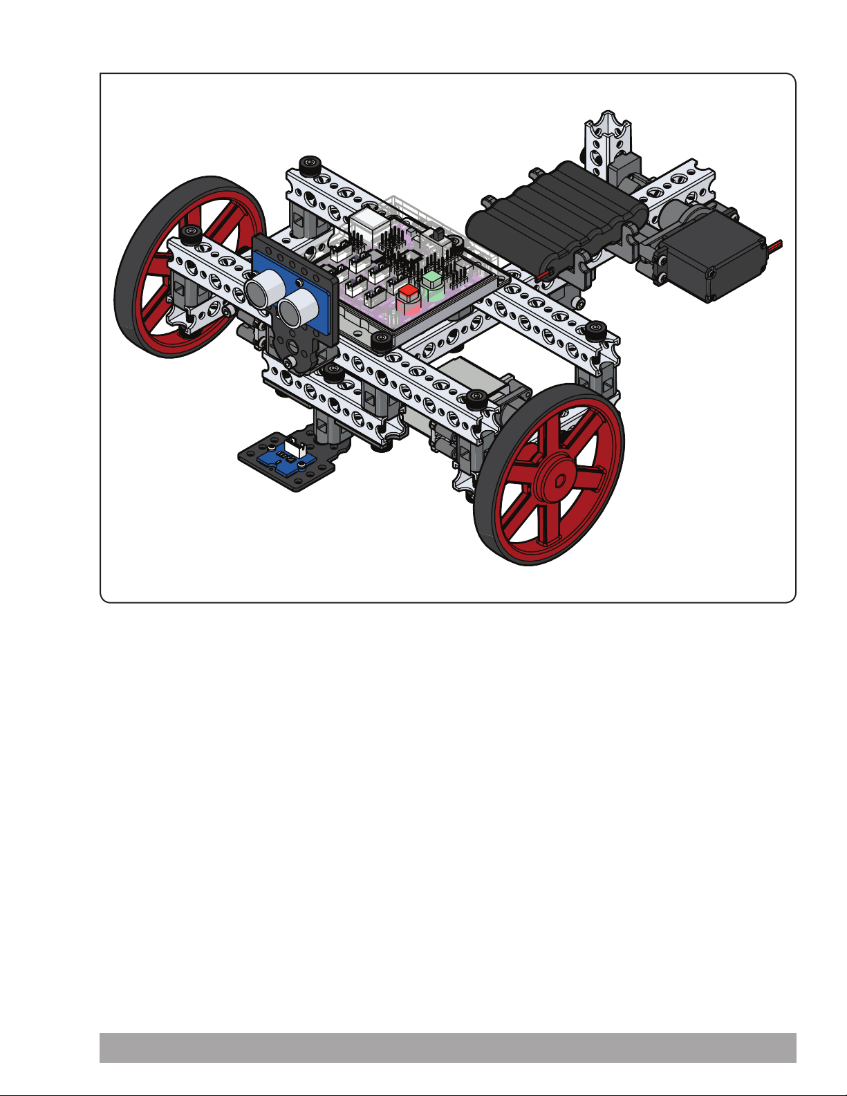
Finished assembly should look like this.
Building and Coding the PULSE CodeeBot 87
Page 90
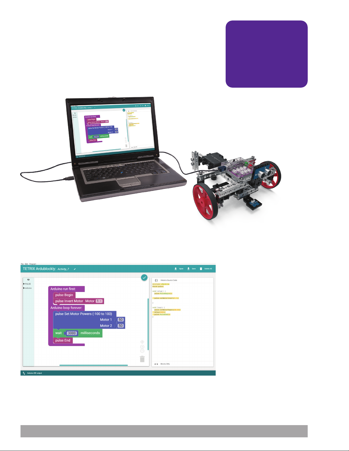
Activity 7: Drive Forward
Introduction
This is your first coding activity with the PULSE Codee Bot, so you’ll keep it simple.
In this activity, you will create a sketch to move the Codee Bot forward for three
seconds and stop, and the program will end.
Building on what you learned in Activity 2, you will add a second DC motor and
have the two motors work together in unison. Being able to use two motors
together in unison is a fundamental requirement for mobile robots.
Parts Needed
Teacher Note: Other factors
can affect building time,
including matters such as set
organization and whether
the builder has a partner.
The building time is only an
estimate. Actual time might
vary.
Open the Program
Let’s start by looking at the example sketch. Open the sketch by selecting
Examples > Activity_7. A new sketch window will open titled Activity_7
(Figure 45).
Figure 45
88 Building and Coding the PULSE CodeeBot
Page 91
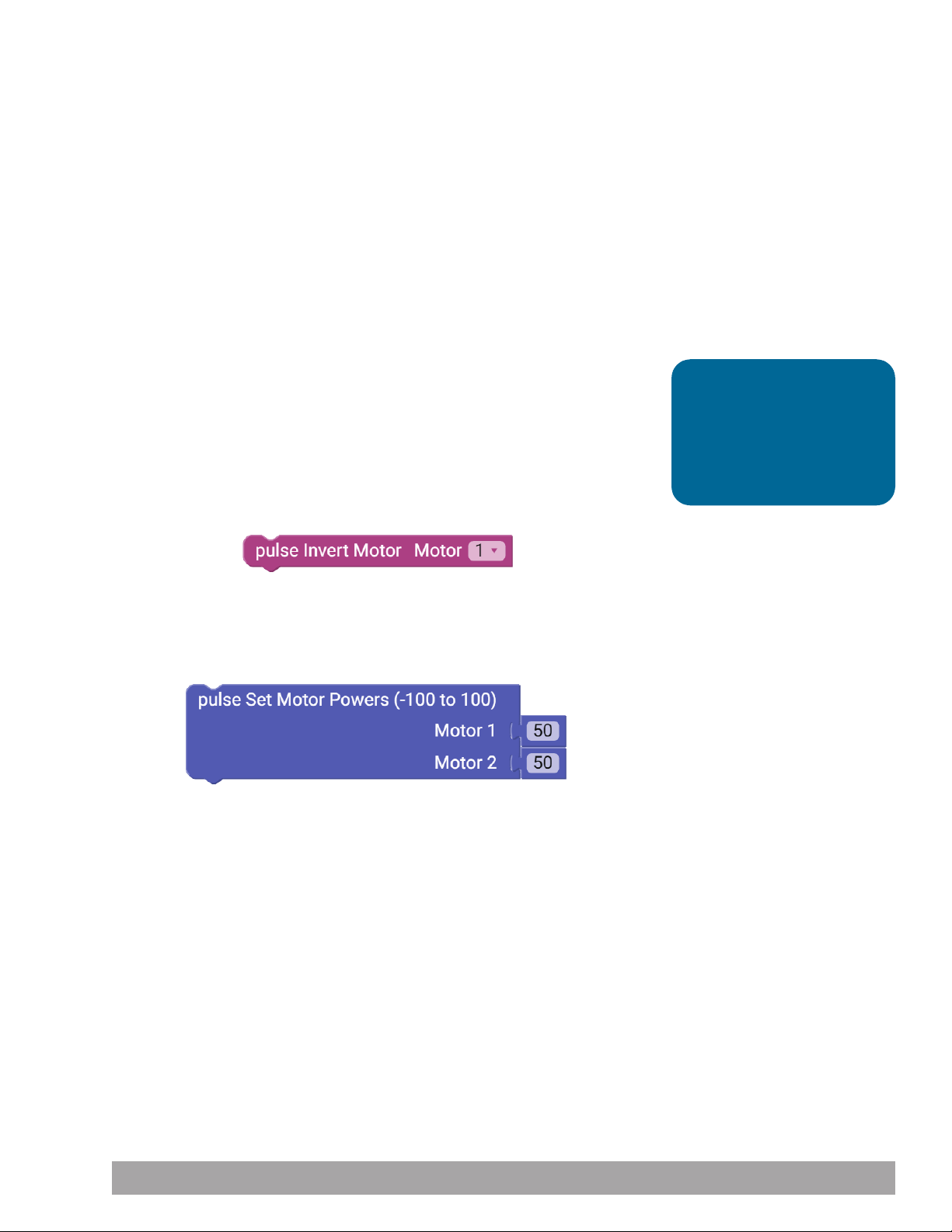
Execute the Code
Before you can upload the sketch to the PULSE, remember to check your
connections. Upload the sketch. The green LED will light up, indicating the code is
ready to execute. When the LED comes on, disconnect the USB cable and set the
Codee Bot on the floor.
Place the Codee Bot so the wheels are at the front of the bot. If your robot goes
backward instead of forward, switch the DC motors’ cords in the ports on the
controller.
Press the green Start button to execute the sketch. Observe the direction and
duration of the Codee Bot’s motion. Based on the sketch comments, did the
behavior match expectations? The Codee Bot should stop moving after three
seconds.
Further Investigate
This sketch introduces three new blocks: pulse Invert Motor, pulse Set Motor
Powers, and pulse End. The pulse Invert Motor block (Figure 46) enables you to
invert the rotational direction of a motor.
When two motors are mounted on opposite sides, this block enables you to give
a single direction command to both motors and have them work together. This
makes your job as a programmer easier. There are two parameters to the function.
The first parameter designates the motor channel, and the second parameter
designates no invert or invert (0 or 1).
Tip: Without the use of
encoders, speeds of DC
motors using the power
commands can vary
depending on the charge
level of the battery.
Figure 46
The pulse Set Motor Powers block (Figure 47) enables you to set the power level of
Motor 1 and Motor 2 at the same time. The two parameters set the speed for each
motor. In this sketch, the motor power for each motor is set at 50 percent.
Figure 47
The pulse End block ends or terminates the sketch. If this block weren’t present,
your program would continue to execute the loop until you stopped the program
by pressing the red button on the controller.
Building and Coding the PULSE CodeeBot 89
Page 92
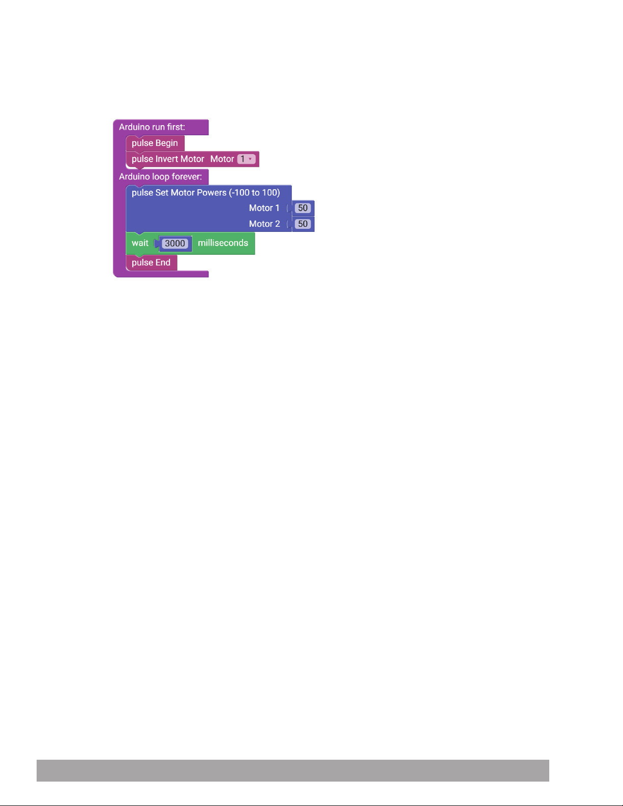
In this simple sketch, all these blocks work together so the robot can move forward
for three seconds and then stop. Because you want the motors to always work
together, the pulse Invert Motor block needs to be used only in the setup part of
the loop block. The pulse Set Motor Powers block tells both motors to move at 50%
power with a single block. To finish the sketch, you use pulse End instead of having
it loop (Figure 48).
Figure 48
Extension Activity
With the example as a reference, try creating a new sketch to move the Codee Bot
forward and stop. Remember what you have learned from your previous activities
and experiment with trying to make the Codee Bot move forward for an amount of
time and then reverse to the same spot.
You have the fundamentals to explore speed because you can measure distance
over time. In your sketch, when you use a specified time, you can physically
measure how far the robot moves. When you change your power parameter, it
should affect the distance traveled in the same time frame.
With that in mind, create a challenge by marking a specified distance on the floor.
Using the data you have collected, program the Codee Bot to get as close to the
specified distance as possible without going over.
90 Building and Coding the PULSE CodeeBot
Page 93
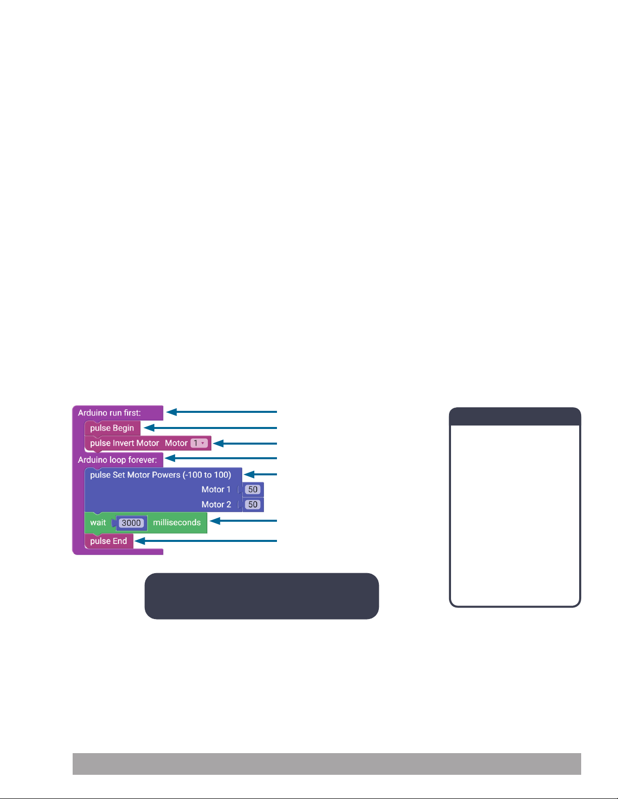
Real-World Link
Trains are machines that can go only forward or backward with the motors they
use. The motors are powered by thrust in either a forward or backward direction. A
train could never directly turn around a corner. That’s why all train tracks are curved
instead of having 90-degree turns.
Careers: railroad worker, railroad conductor, locomotive engineer
STEM Connections
• Science
Ĕ Kinetic energy
Ĕ Speed
• Technology
Ĕ Direct drive
Ĕ DC motors
• Engineering
Ĕ Steering mechanism
Ĕ Programming
• Math
Ĕ Rotation
Ĕ Wheel circumference
Block-Text Correlation
Note: Use the pulse Invert Motor block to program
the two motors to go in opposite directions.
void setup() {
pulse.PulseBegin();
pulse.setMotorInvert(1,1);
void loop() {
pulse.setMotorPowers(50,50);
delay(3000);
pulse.PulseEnd();
Arduino Source Code
#include <PULSE.h>
PULSE pulse;
void setup() {
pulse.PulseBegin();
pulse.setMotorInvert(1,1);
}
void loop() {
pulse.setMotorPowers(50,50);
delay(3000);
pulse.PulseEnd();
}
Building and Coding the PULSE CodeeBot 91
Page 94
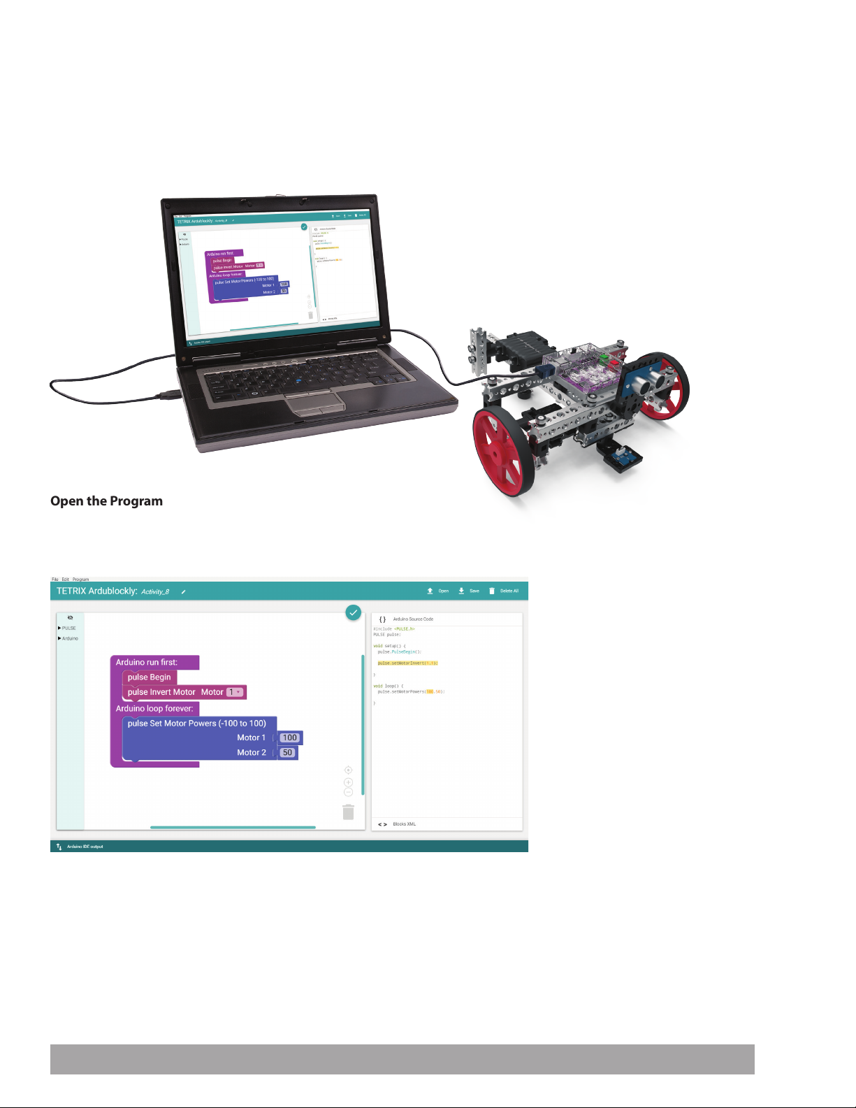
Activity 8: Drive in a Circle
Introduction
For your eighth activity, you will apply your knowledge of motors to create a new
behavior. While being able to move straight is important, you need to be able
to expand on that and make turns. This activity will have your PULSE Codee Bot
driving in circles by using different motor powers as the motors work in unison.
Parts Needed
Open the Program
Let’s start by looking at the example sketch. Open the sketch by selecting
Examples > Activity_8. A new sketch window will open titled Activity_8
(Figure 49).
Figure 49
92 Building and Coding the PULSE CodeeBot
Page 95

Execute the Code
Before you can upload the sketch to the PULSE, remember to check your
connections. Upload the sketch. The green LED will light up, indicating the code
is ready to execute. When this has occurred, disconnect the USB cable and set the
Codee Bot on the floor.
Place the Codee Bot so the wheels are at the front of the bot. If your robot goes
backward instead of forward, switch the DC motors’ cords in the ports on the
controller.
Tip: The Codee Bot might
struggle to overcome the
friction of carpet. If possible,
test your bot on a smooth
surface.
Press the green Start button to execute the sketch. Observe the direction and
duration of the Codee Bot’s motion. Press the red Stop/Reset button to end the
sketch. Based on the sketch comments, did the behavior match expectations?
Further Investigate
While this sketch does not use any new blocks, it should lead to a deeper
understanding of how motors work in unison to create a specified behavior.
All the blocks in this sketch work together to make the Codee Bot move in a circle.
Because you want the motors to always work together, the pulse Invert Motor block
is used only in the setup part of the loop. The pulse Set Motor Powers block tells
both motors to move at different speeds in a single function. One motor is set to
100% while the other is set to 50%, resulting in a circular motion.
Extension Activity
With the example as a reference, try creating a new sketch to move the Codee Bot
in a different-size circle. Remember what you have learned from your previous
activities and experiment with different parameters to make the circle diameter
larger or smaller. Challenge yourself to add behaviors. What would it take to make
your robot drive in an oval or a figure eight?
Real-World Link
If you’ve ridden by a golf course, you have probably seen automatic sprinklers
operating. These sprinklers go in a circle spraying water in a 360-degree radius.
These sprinklers are programmed to turn off and on at different times. It’s important
that the motor turn the sprinkler head so it covers the entire area of its range.
Tip: You will need about six
feet, or two meters, of open
space on the floor for the
robot to complete a circle.
Careers: groundskeeper, farm equipment mechanic, irrigation engineer
STEM Connections
• Science
Ĕ Power
Ĕ Speed
• Technology
Ĕ Motor control
Ĕ Motor precision
• Engineering
Ĕ Machine design
Ĕ Geometric patterns
• Math
Ĕ Radius
Ĕ Diameter
Building and Coding the PULSE CodeeBot 93
Page 96
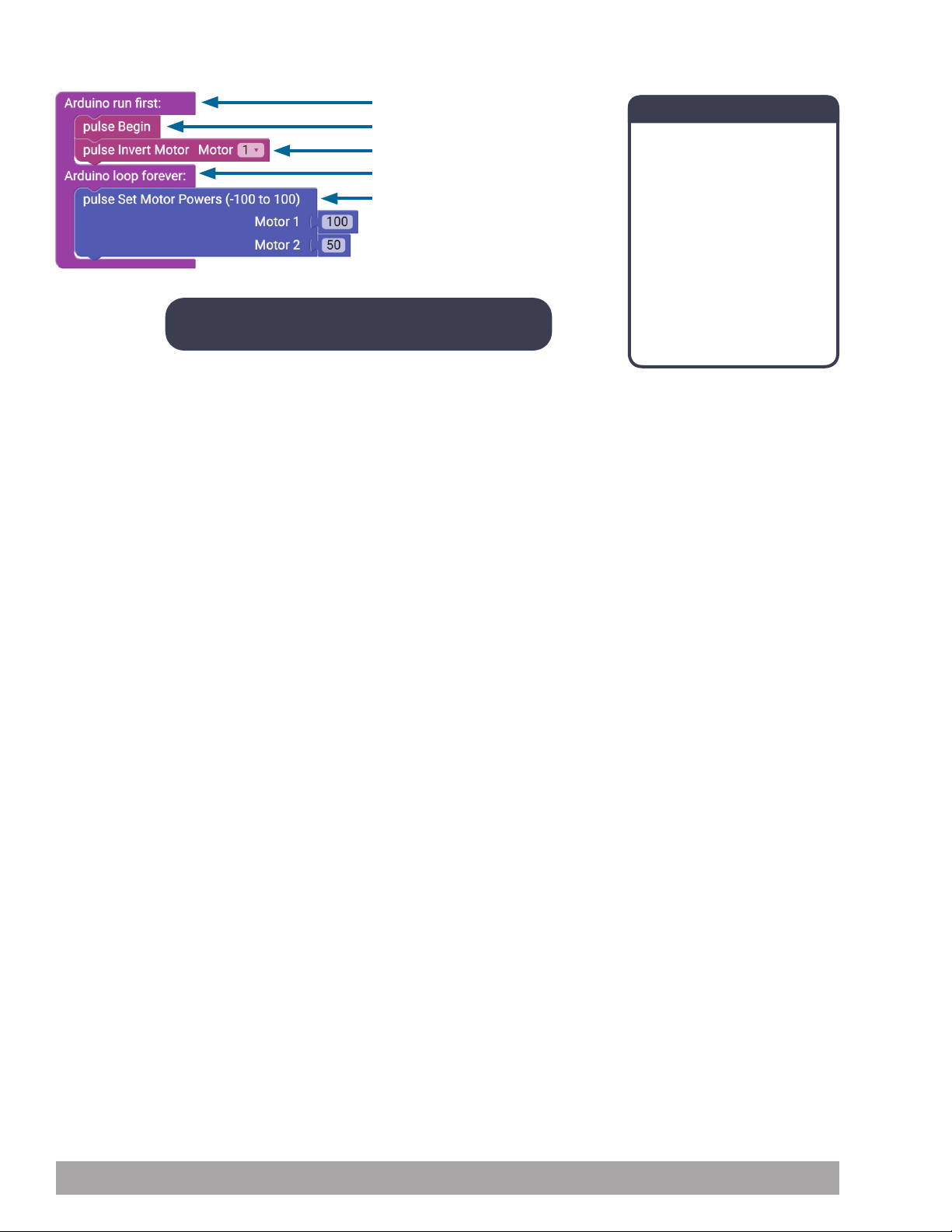
Block-Text Correlation
void setup() {
pulse.PulseBegin();
pulse.setMotorInvert(1,1);
void loop() {
pulse.setMotorPowers(100,50);
Note: Motor 1 is turning at twice the power of Motor 2.
Arduino Source Code
#include <PULSE.h>
PULSE pulse;
void setup() {
pulse.PulseBegin();
pulse.setMotorInvert(1,1);
}
void loop() {
pulse.setMotorPowers(100,50);
}
94 Building and Coding the PULSE CodeeBot
Page 97
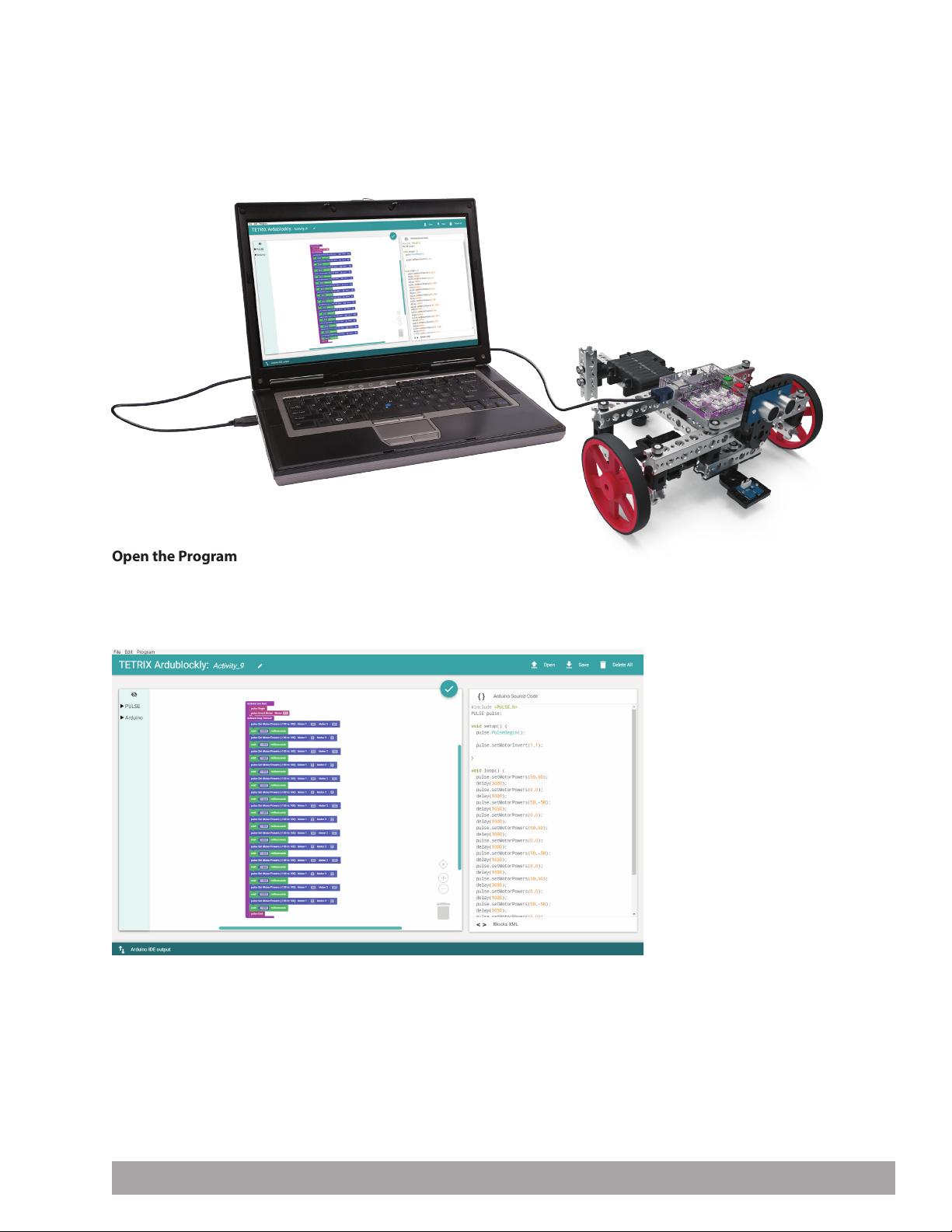
Activity 9: Drive in a Square
Introduction
Now, you will continue to build your navigational skills with the PULSE Codee
Bot by giving your robot the ability to make 90-degree turns. The ability to make
90-degree turns will be used to make the Codee Bot drive in a square.
Parts Needed
Open the Program
Let’s start by looking at the example sketch. Open the sketch by selecting
Examples > Activity_9. A new sketch window will open titled Activity_9
(Figure 50).
Figure 50
Building and Coding the PULSE CodeeBot 95
Page 98
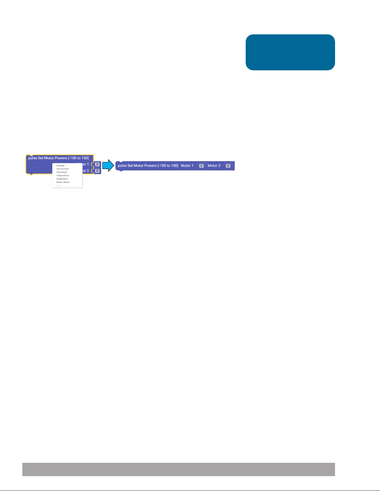
Execute the Code
Before you can upload the sketch to the PULSE, remember to check your
connections. Upload the sketch. The green LED will light up, indicating the code
is ready to execute. When this has occurred, disconnect the USB cable and set the
Codee Bot on the floor.
Press the green Start button to execute the sketch. Observe the direction and
duration of the Codee Bot’s motion. Based on the sketch comments, did the
behavior match expectations?
Further Investigate
When you have a lot of blocks on screen, it can hard to see your whole program.
You can use the zoom in and out feature. Also, some blocks can be changed to
inline inputs. The pulse Set Motor Powers block can be changed to an inline input.
Below is an example of how this block can change appearance (Figure 51). This
does not affect your program.
Figure 51
Tip: Depending on the
surface type, your bot might
not execute a perfect square.
This sketch has a lot to it, but it is made of functions that you have used before. You
have just combined multiple sequential behaviors to create one larger behavior – in
this case, a square.
An important thing to understand about this program is that you are using dead
reckoning to program the robot’s square driving path. Dead reckoning is simply
using time as the basis for controlling a motor. For instance, to make a right-hand
turn, you are commanding the motors to turn on in opposite directions at 50%
power and run for 1,650 milliseconds.
You estimate that if you spin the motors at a certain rpm for a certain time, you
should come close to making a 90-degree right turn. However, this is not always
accurate because the amount that your robot’s battery is charged can vary, and any
wheel slippage on the surface you are working on can cause a variation in results.
You are using dead reckoning to make a right turn.
All the functions in this sketch work together to make the Codee Bot move in a
square (Figure 52). Because you want the motors to always work together, the pulse
Invert Motor block needs to be used only in the setup part of the loop. The pulse
Set Motor Powers block tells both motors to move at different speeds in a single
function.
96 Building and Coding the PULSE CodeeBot
Page 99
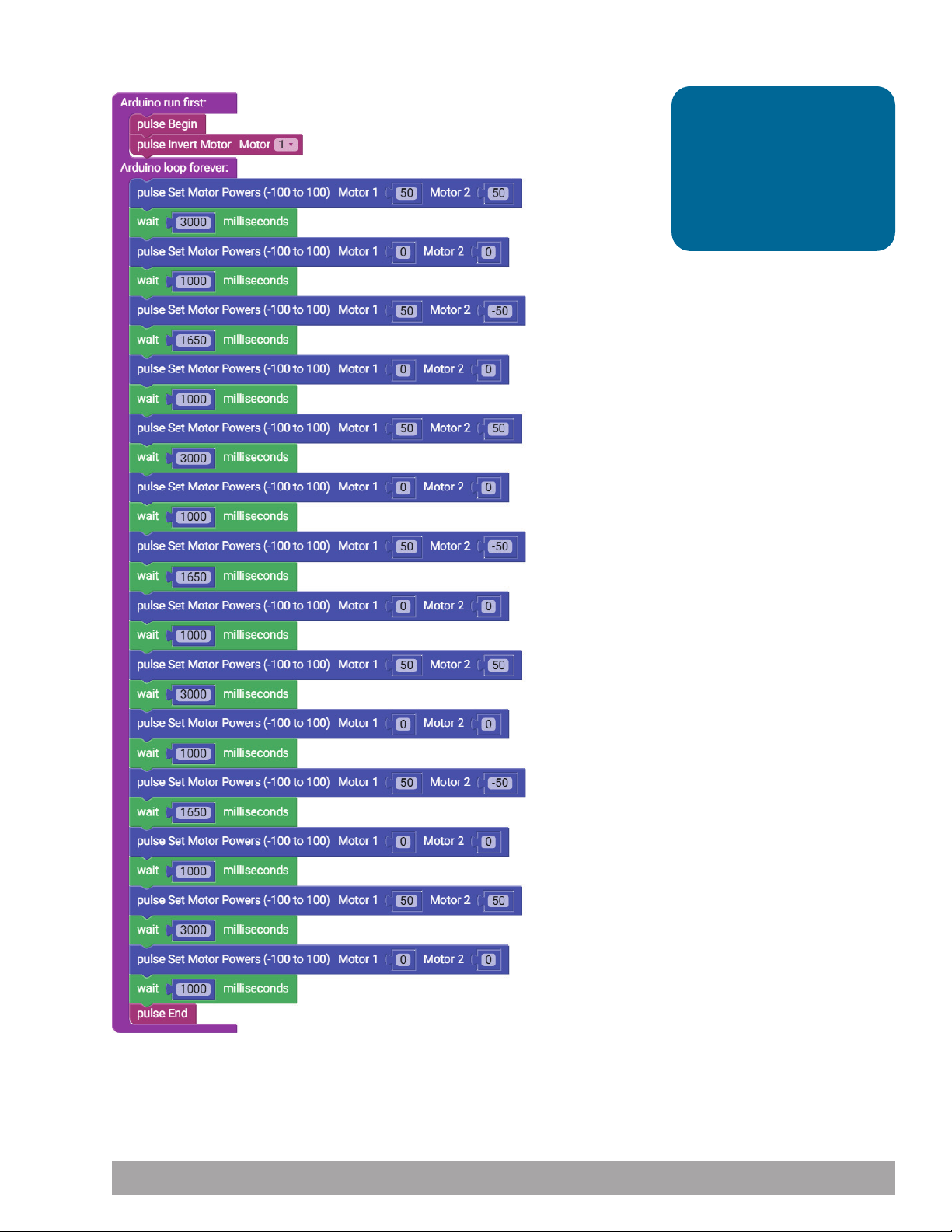
Program Breakdown
Drive forward
Brake
Turn 1
Brake
Drive forward
Brake
Tip: Adjust the timing of the
turns if the robot doesn’t
turn at right angles. For
example, you can change the
time from 1650 to 1300. The
charge of the battery can
affect the turns.
Turn 2
Brake
Drive forward
Brake
Turn 3
Brake
Drive forward
Brake
Figure 52
Building and Coding the PULSE CodeeBot 97
Page 100

Extension Activity
With the example as a reference, try creating a new sketch to move the Codee
Bot in a square. Remember what you have learned from your previous activities
and experiment with different parameters to make the square larger or smaller.
Challenge yourself to create complex paths beyond a square. Try tracing out some
of the alphabet or navigate through a simple maze using dead reckoning.
Real-World Link
Some transportation vehicles take the same route time after time. If a vehicle is in
a warehouse, it could transport items to three different locations before returning.
Then it could pick up more items and move in a square to transport them.
Careers: mapping technician, air traffic controller, manufacturing engineer
STEM Connections
• Science
Ĕ Distance
Ĕ Time
• Technology
Ĕ Microprocessor time
Ĕ Turning radius
• Engineering
Ĕ Motor power
Ĕ Braking
• Math
Ĕ Angles of a square
Ĕ Measurement of angles
98 Building and Coding the PULSE CodeeBot
 Loading...