

Page 1
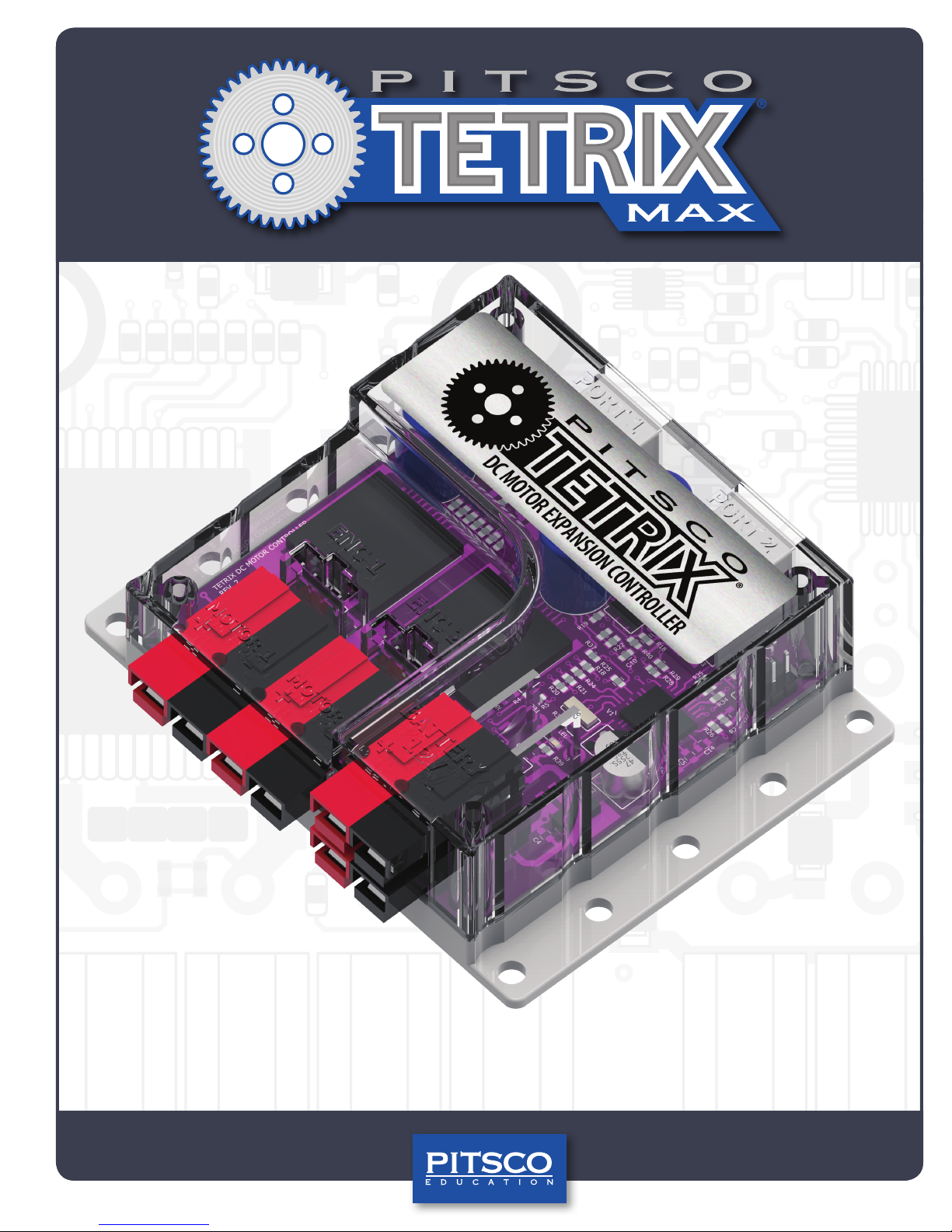
TETRIX® DC Motor Expansion Controller
Technical Guide
44559
Page 2

Content advising by Paul Uttley.
SolidWorks® Composer™ and KeyShot® renderings by Tim Lankford, Brian Eckelberry, and Jason Redd.
Desktop publishing by Todd McGeorge.
©2018 Pitsco, Inc., 915 E. Jefferson, Pittsburg, KS 66762
All rights reserved. This product and related documentation are protected by copyright and are distributed under licenses
restricting their use, copying, and distribution. No part of this product or related documentation may be reproduced in any
form by any means without prior written authorization of Pitsco, Inc.
All other product names mentioned herein might be the trademarks of their respective owners.
A downloadable PDF of the most recent version of this guide can be found at
Pitsco.com/TETRIX-MAX-DC-Motor-Expansion-Controller#resources.
This device complies with Part 15 of the FCC Rules. Operation is subject to the following two conditions: (1)
this device may not cause harmful interference, and (2) this device must accept any interference received,
including interference that may cause undesired operation.
V1.0
02/18
Page 3
TETRIX® DC Motor Expansion Controller Technical Guide
General Description
The TETRIX® MAX DC Motor Expansion Controller is a DC motor expansion peripheral designed to allow the addition of
multiple DC motors to the PRIZM® Robotics Controller. The device provides an additional two DC motor output channels
and two quadrature encoder inputs for increased motor control capacity. Additional expansion controllers can be daisychained for a total of four motor expansion controllers connected to the PRIZM at one time. The onboard firmware provides
a comprehensive set of programmable motor control functions.
The TETRIX MAX DC Motor Expansion Controller features the following:
• Connects to the PRIZM expansion port, enabling users to control up to two additional 12-volt DC motors
• Up to four motor controllers can be connected to the PRIZM expansion port.
• Has two H-bridge outputs to control the speed and direction of two DC motors
• Includes two quadrature encoder input ports
• Additional power and expansion ports support daisy chain configurations.
• Can be connected to the LEGO® EV3 Brick and National Instruments’ myRIO. Software blocks can be downloaded
from the product page for this controller at Pitsco.com.
What’s Included
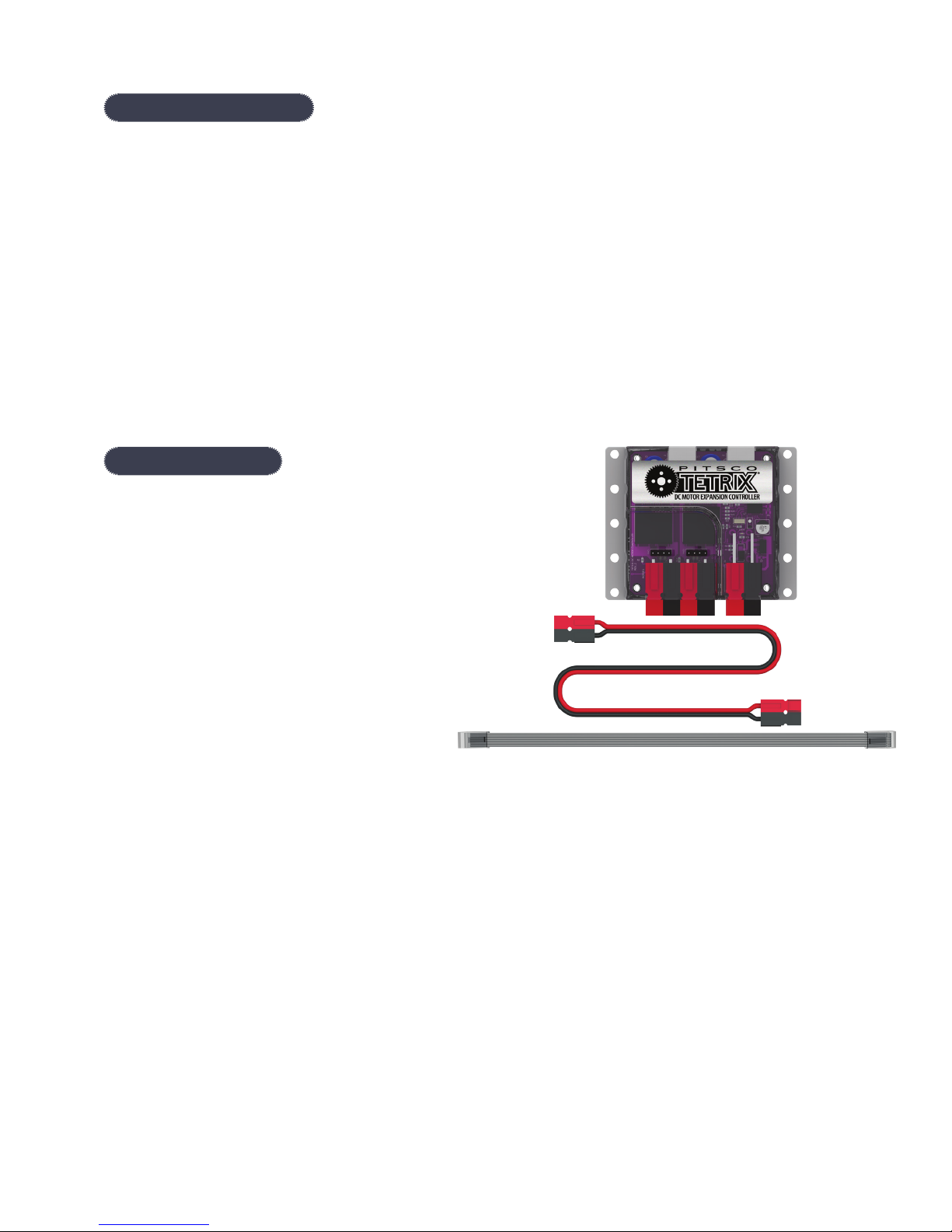
• TETRIX MAX DC Motor Expansion Controller
• TETRIX MAX Powerpole Extension Cable
• Daisy chain data cable
Page 4
Connections
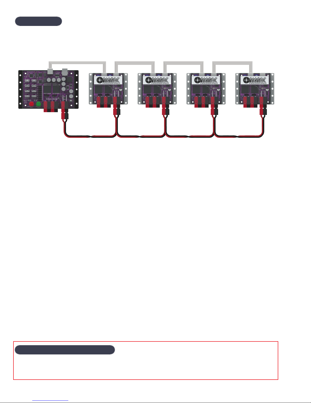
The DC motor expansion controller connects to the PRIZM battery power expansion terminals using the included
Powerpole extension cable. The motor controller’s data port connects to the PRIZM expansion port using the included data
cable. Additional motor controllers can be daisy-chained for increased motor channel capacity. Up to four motor controllers
can be daisy-chained to a single i2C data bus.
The four expansion controllers can be a mix of DC and servo motor expansion controllers. The TETRIX Servo Motor
Expansion Controllers (44355) can be added to increase the number of servo motor channels for programming and control.
Each motor controller in the daisy chain must have a unique i2C address, or ID, in order to communicate. By default, the
DC motor expansion controller uses ID Number 1, and the servo expansion controller uses ID Number 2. The unique ID of
any additional controllers in the daisy chain can be set or changed by using software commands. ID numbers supported
by the PRIZM Arduino Library are 1, 2, 3, and 4. There are programming examples in the TETRIX PRIZM Arduino Library that
demonstrate how to read a motor controller ID and how to set and change the ID.
The operation of the motor controller is very similar to the PRIZM controller because they use comparable command
formats. The TETRIX PRIZM Arduino Library has been updated to support the DC motor expansion controller. The TETRIX
PRIZM Arduino Library contains several sketches in the examples folder that demonstrate how to program using the DC
motor expansion controller and PRIZM. A thorough understanding of how to program using PRIZM and completion of the
activities within the TETRIX PRIZM Robotics Controller Programming Guide are highly recommended to better understand
the programming application of the DC motor expansion controller. The appendix provides a detailed description of each
function used by the TETRIX PRIZM Arduino Library for interfacing with the DC motor expansion controller. Please be sure
to download and install the latest TETRIX PRIZM Arduino Library from the TETRIX website at Pitsco.com/TETRIX-PRIZM-
Robotics-Controller#downloads.
Important Safety Information
Caution: Use only a TETRIX battery pack that is equipped with an in-line safety fuse. Failure to do so could result in damage
or injury. Connect the TETRIX battery pack to either the top or bottom red/black power inlet row at the battery connection
port. Do not connect two battery packs to the PRIZM controller.
Page 5
Attaching the DC Motor Expansion Controller
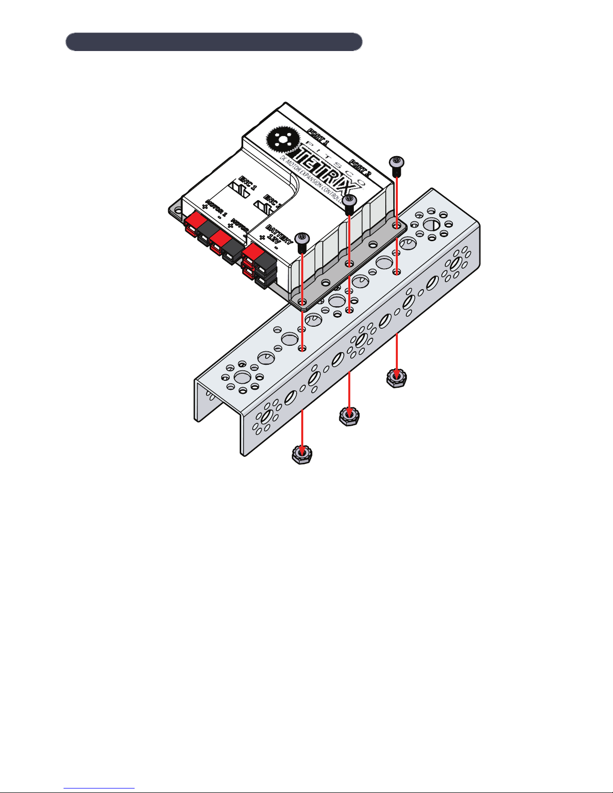
The DC motor expansion controller mounting holes are spaced to align with the TETRIX hole pattern. The expansion
controller can be attached to the TETRIX building elements using the screw and nut hardware included in the TETRIX
robotics sets.
Page 6
Supported Software and Additional Resources
The DC motor expansion controller is designed with flexibility in mind and can interface with any master controller with
an i2C communications bus. Pitsco Education provides software support materials and other resources that enable the DC
motor controller to interface with the PRIZM controller, the LEGO MINDSTORMS® EV3 Brick, and the National Instruments
myRIO.
The DC motor controller can interface with other devices such as Raspberry Pi or Arduino, but software support is not
provided.
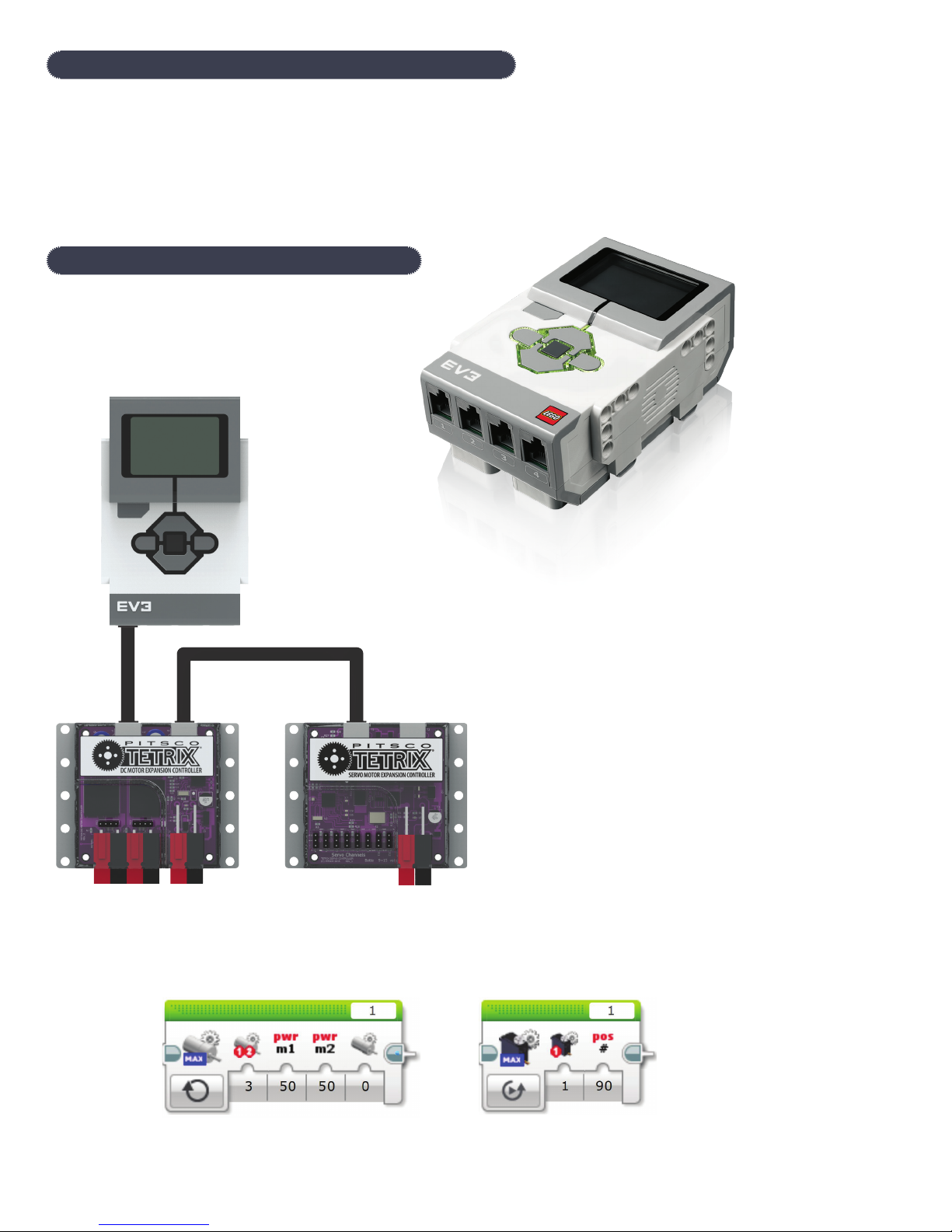
Support for LEGO MINDSTORMS EV3
While the DC motor expansion controller has been
designed to work primarily with the TETRIX PRIZM
Robotics Controller, it can also be connected directly
to the LEGO EV3 Brick for programming and control of
TETRIX DC gearhead motors.
You will need a TETRIX MAX 12-volt rechargeable battery
and power switch kit to supply power to the controller.
The daisy chain data cable that comes with the DC motor
expansion controller will connect to the EV3 sensor ports.
EV3 programming blocks for the DC motor expansion controller are available for free download at
Pitsco.com/TETRIX-MAX-DC-Motor-Expansion-Controller#downloads.
Page 7
motor controllers
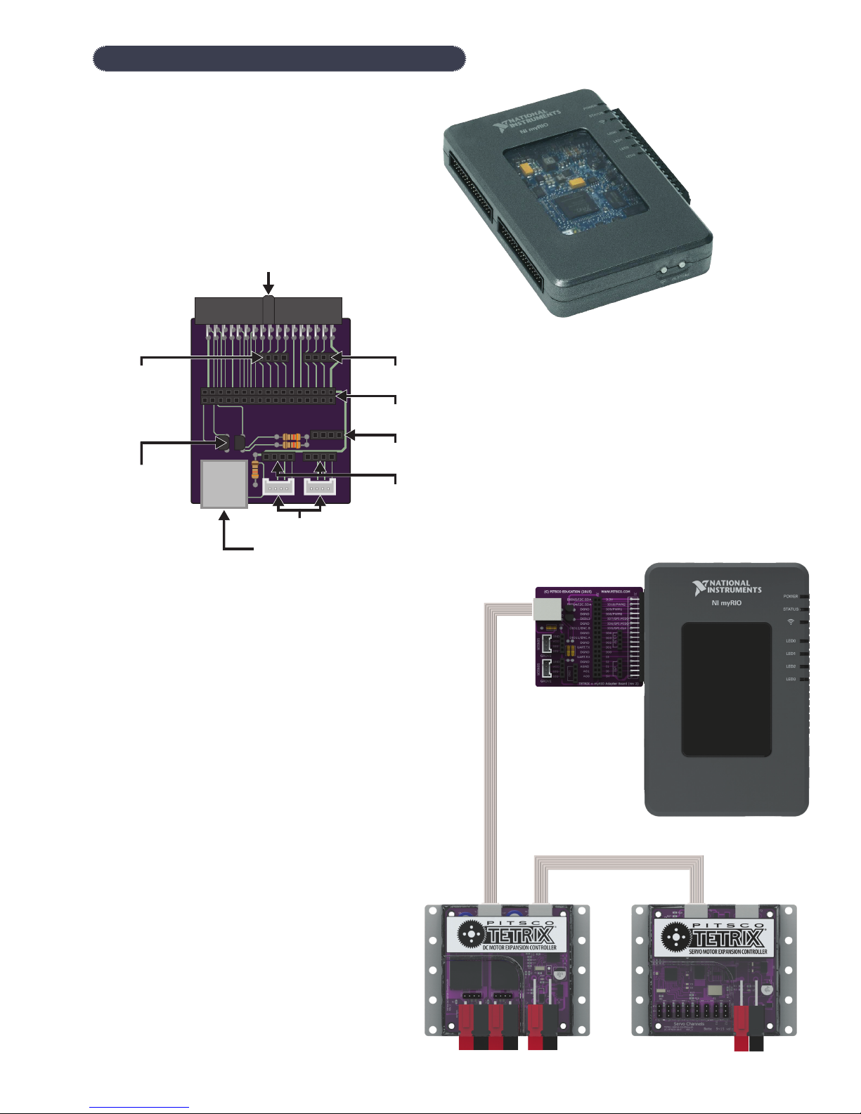
Support for National Instruments myRIO
In addition, there is support for the National Instruments
myRIO platform to enable TETRIX DC motor control using
the LabVIEW™ programming language.
34-pin MXP connector to NI myRIO
+3.3 V expansion
port
Built-in
logic-level
shifting
circuit for
connection of
TETRIX motor
controllers
to NI myRIO i2C
bus
2x Grove sensor
family connections
LEGO style i2C port connector
for connection of TETRIX
+5 V expansion
port
34-pin NI myRIO I/O
expansion port
GND expansion
port
2x Grove sensor
family connections
A free downloadable TETRIX LabVIEW control palette and user
documentation are available for download at
Pitsco.com/Competitions,-Clubs,-and-Programs/WorldRobot-Olympiad.
A hardware adapter (41306) enables
easy connection of expansion
controllers to the myRIO MXP ports.
Page 8
General Hardware Specifications
This section provides details on the communications of the DC motor expansion controller. This information can be used to
interface with any master controller with an i2C communications bus.
Power: 12 volts DC using TETRIX MAX NiMH fuse-protected battery pack; blue LED power indicator
DC motor ports: 2 Powerpole connections; H-bridge controlled; 10 A continuous each channel; 20 A peak
Recommended motor: TETRIX TorqueNADO™ (44260)
Motor indication: Motor power and direction LED indicators; red and green; one set for each channel
Constant power (-100% to 100%)
PID constant speed (degrees per second)
DC motor control modes:
Battery voltage monitoring: 0-18 volt range
Battery connection port:
i2C data port:
Motor encoder port:
PID constant speed to encoder count and hold position
PID constant speed to encoder degrees and hold position
Brake or coast stop mode
DC motor current monitoring (all modes)
Powerpole type; additional port for daisy-chaining battery power to additional motor
controllers
2 ports total sharing the same bus; one port used for input, the second for output to
additional daisy-chained motor controllers
2 quadrature ports; ENC1 and ENC2; 5 volts DC, 50 mA max; Spec: 360 CPR, 1,440 PPR;
Type: Hall effect
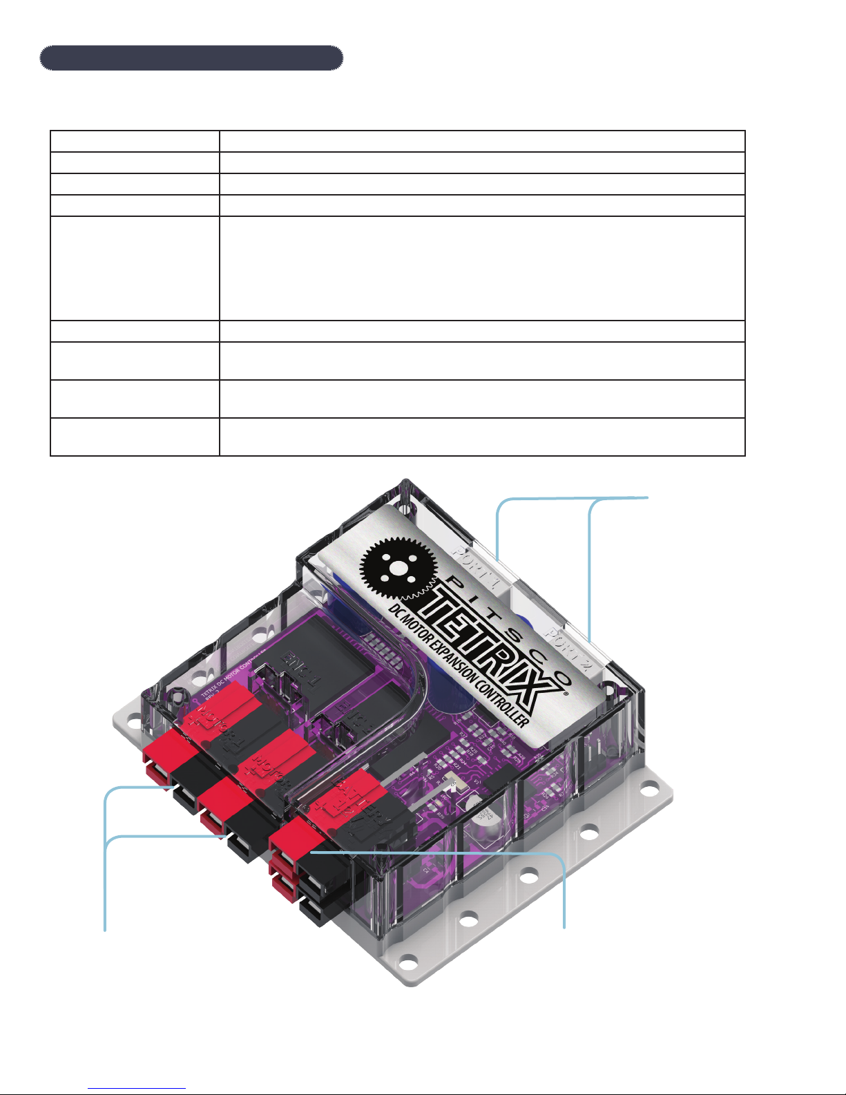
2 data ports
Connect to
the PRIZM
expansion
port using
the included
data cable.
2 DC motor ports
Battery connection port
Power is supplied to the controller
from the PRIZM battery outlet port
using the included Powerpole battery
conversion cable.
Page 9

TETRIX MAX DC Motor Expansion Controller Library
Following is a quick reference for each expansion controller function supported by the TETRIX PRIZM Arduino Library.
Note: Unless changed, the default ID# for the DC motor expansion controller is 1.
readDCFirmware(ID#);
setExpID(ID#);
readExpID();
WDT_STOP(ID#);
ControllerEnable(ID#);
ControllerReset(ID#);
setMotorPower(ID#, motor#, power);
setMotorPowers(ID#, power1, power2);
setMotorSpeed(ID#, motor#, speed);
setMotorSpeeds(ID#, speed1, speed2);
setMotorTarget(ID#, motor#, speed, target);
setMotorTargets(ID#, speed1, target1, speed2, target2);
setMotorDegree(ID#, motor#, speed, degrees);
setMotorDegrees(ID#, speed1, degrees1, speed2, degrees2);
setMotorInvert(ID#, motor#, invert);
readMotorCurrent(ID#, motor#);
readMotorBusy(ID#, motor#);
readEncoderCount(ID#, enc#);
readEncoderDegrees(ID#, enc#);
resetEncoder(ID#, enc#);
resetEncoders(ID#);
readBatteryVoltage(ID#);
setMotorSpeedPID(ID#, P, I, D);
setMotorTargetPID(ID#, P, I, D);
Page 10

TETRIX MAX DC Motor Expansion Controller Arduino Library Functions Chart
Please be sure to download and install the latest version of the TETRIX PRIZM Arduino Library for the most up-to-date
programming features and functionality.
All the DC motor control functions that implement PID control require encoder input data. For these functions to execute
accurately, the motor encoder must be a TETRIX type or one that matches the TETRIX motor encoder specification. Please
refer to the TETRIX TorqueNADO motor specifications table at Pitsco.com/TETRIX-MAX-TorqueNADO-Motor-with-
Encoder#resources for the motor and encoder technical parameters. The examples in the Coding Example column are
shown for the controller ID# set to 1. The ID# must match the controller or controllers’ ID# for proper communication.
Unless changed, the DC motor expansion controller’s default ID# is 1. The first parameter in the function is always the
controller ID#.
Description Function Coding Example (for controller ID = 1)
Read DC Controller Firmware
Version
Reads the version number of firmware.
Set/Change Expansion Controller ID
Number
Sets/changes the unique i2C ID
address of the expansion controller.
Read the Expansion Controller ID
Number
Reads the i2C address/ID of the
expansion controller.
Watchdog Timer Time-Out
readDCFirmware(ID#);
Data Type:
ID# = integer
Data Type Returned:
Unsigned integer
setExpID(ID#);
Data Type:
ID# = integer
readExpID();
Data Type: None
Data Type Returned:
value = integer
WDT_STOP(ID#);
readDCFirmware(1);
Return the DC motor controller’s firmware
version.
setExpID(3);
Set the ID of the connected expansion
controller to “3.”
Important: Only the controller that is
being changed can be connected to the
i2C bus when calling this function.
readExpID();
Return the i2C address/ID of the
connected expansion controller.
Important: Only the controller that is
being read can be connected to the i2C
bus when calling this function.
WDT_STOP(1);
Forces a watchdog timer reset of the
expansion controller’s processor.
Send Controller Enable
Sends an enable byte to the expansion
controller to begin receiving motor
commands.
Send Controller Reset
Sends a reset command byte causing
the controller’s firmware to a full reset.
All conditions are set to power-up
defaults after a reset occurs.
Data Type:
ID# = integer
ControllerEnable(ID#);
Data Type:
ID# = integer
ControllerReset(ID#);
Data Type:
ID# = integer
Command the expansion controller to do
a processor reset.
ControllerEnable(1);
Send an enable command byte.
ControllerReset(1);
Send a firmware reset command byte.
Page 11

Description Function Coding Example (for controller ID = 1)
Set DC Motor Power
setMotorPower(ID#, motor#, power);
setMotorPower(1, 1, 50);
Sets the power level and direction of
a TETRIX DC Motor connected to the
motor ports. Power level range is 0 to
100. Direction is set by the sign (+/-) of
the power level. Power level 0 = stop in
coast mode. Power level 125 = stop in
brake mode.
Set DC Motor Powers
Simultaneously sets the power level
and direction of both TETRIX DC
Motors connected to the motor ports.
Both Motor 1 and Motor 2 channel
parameters are set with a single
statement. The power level range is 0
to 100. Direction is set by the sign (+/-)
of the power level. Power level 0 = stop
in coast mode. Power level 125 = stop
in brake mode.
Data Type:
ID# = integer
motor# = integer
power = integer
Data Range:
motor# = 1 or 2
power = -100 to 100
or
power = 125 (brake mode)
setMotorPowers(ID#, power1,
power2);
Data Type:
ID# = integer
power1 = integer
power2 = integer
Data Range:
power1 = -100 to 100
power2 = -100 to 100
or
Spin Motor 1 clockwise at 50% power.
setMotorPower(1, 2, -50);
Spin Motor 2 counterclockwise at 50%
power.
setMotorPower(1, 1, 0);
Turn off Motor 1 in coast mode.
setMotorPower(1, 2, 125);
Turn off Motor 2 in brake mode.
setMotorPowers(1, 50, 50);
Spin Motor 1 and Motor 2 clockwise at
50% power.
setMotorPowers(1, -50, 50);
Spin Motor 1 counterclockwise and Motor
2 clockwise at 50% power.
setMotorPowers(1, 0, 0);
Turn off Motor 1 and Motor 2 in coast
mode.
setMotorPowers(1, 125, 125);
Turn off Motor 1 and Motor 2 in brake
mode.
power1 = 125 (brake mode)
power2 = 125 (brake mode)
Page 12

Description Function Coding Example (for controller ID = 1)
Set DC Motor Speed
setMotorSpeed(ID#, motor#, speed);
setMotorSpeed(1, 1, 360);
Uses velocity PID control to set the
constant speed of a TETRIX DC Motor
with a TETRIX motor encoder installed.
The speed parameter range is 0 to 720
degrees per second (DPS). The sign
(+/-) of the speed parameter controls
direction of rotation.
Set DC Motor Speeds
Uses velocity PID control to
simultaneously set the constant
speeds of both TETRIX DC Motor
channels with TETRIX motor encoders
installed. Both Motor 1 and Motor
2 channel parameters are set with a
single statement. The speed parameter
range is 0 to 720 degrees per second
(DPS). The sign (+/-) of the speed
parameter controls direction of
rotation.
Set DC Motor Target
Implements velocity and positional
PID control to set the constant speed
and the encoder count target holding
position of a TETRIX DC Motor with a
TETRIX encoder installed. The speed
parameter range is 0 to 720 degrees
per second (DPS). The encoder count
target position is a signed long integer
from -2,147,483,648 to 2,147,483,647.
Each encoder count = 1/4-degree
resolution.
Data Type:
ID# = integer
motor# = integer
speed = integer
Data Range:
motor# = 1 or 2
speed = -720 to 720
setMotorSpeeds(ID#, speed1,
speed2);
Data Type:
ID# = integer
speed1 = integer
speed2 = integer
Data Range:
speed1 = -720 to 720
speed2 = -720 to 720
setMotorTarget(ID#, motor#, speed,
target);
Data Type:
ID# = integer
motor# = integer
speed = integer
target = long
Spin Motor 1 clockwise at a constant
speed of 360 DPS.
setMotorSpeed(1, 1, -360);
Spin Motor 1 counterclockwise at a
constant speed of 360 DPS.
setMotorSpeeds(1, 360, 360);
Spin Motor 1 and Motor 2 clockwise at a
constant speed of 360 DPS.
setMotorSpeeds(1, 360, -360);
Spin Motor 1 clockwise and Motor 2
counterclockwise at a constant speed of
360 DPS.
setMotorSpeeds(1, 180, -180);
Spin Motor 1 clockwise and Motor 2
counterclockwise at a constant speed of
180 DPS.
setMotorTarget(1, 1, 360, 1440);
Spin Motor 1 at a constant speed of 360
DPS until encoder 1 count equals 1,440.
When at encoder target count, hold
position in a servo-like mode.
setMotorTarget(1, 2, 180, -1440);
Spin Motor 2 at a constant speed of 180
DPS until encoder 2 count equals -1,440 (1
revolution). When at encoder target count,
hold position in a servo-like mode.
Data Range:
motor# = 1 or 2
speed = 0 to 720
target = -2147483648 to 2147483647
Page 13

Description Function Coding Example (for controller ID = 1)
Set DC Motor Targets
setMotorTargets(ID#, speed1,
target1, speed2, target2);
setMotorTargets(1, 360, 1440, 360,
1440);
Implements velocity and positional
PID control to simultaneously set the
constant speeds and the encoder
count target holding positions of both
TETRIX DC Motor channels each with
TETRIX encoders installed. Both Motor
Data Type:
ID# = integer
speed1 = integer
Spin Motor 1 and Motor 2 at a constant
speed of 360 DPS until each motor
encoder count equals 1,440. When a
motor reaches its encoder target count,
hold position in a servo-like mode.
1 and Motor 2 channel parameters are
set with a single statement. The speed
parameter range is 0 to 720 degrees
per second (DPS). The encoder count
target position is a signed long integer
from -2,147,483,648 to 2,147,483,647.
Each encoder count = 1/4-degree
resolution.
target1 = long
speed2 = integer
target2 = long
Data Range:
setMotorTargets(1, 360, 1440, 180,
2880);
Spin Motor 1 at a constant speed of 360
DPS until encoder 1 count equals 1,440.
Spin Motor 2 at a constant speed of 180
DPS until encoder 2 equals 2,880. Each
motor will hold its position in a servo-like
mode when it reaches the encoder target.
speed1 = 0 to 720
Set Motor Degree
Implements velocity and positional
PID control to set the constant speed
and the degree target holding position
of a TETRIX DC Motor with a TETRIX
encoder installed. The speed parameter
range is 0 to 720 degrees per second
(DPS). The encoder degrees target
position is a signed long integer from
-536,870,912 to 536,870,911 with a
1-degree resolution.
target1 = -2147483648 to
2147483647
speed2 = 0 to 720
target2 = -2147483648 to
2147483647
setMotorDegree(ID#, motor#, speed,
degrees);
Data Type:
ID# = integer
motor# = integer
speed = integer
degrees = long
Data Range:
motor# = 1 or 2
speed = 0 to 720
Note: One encoder count equals
1/4-degree resolution. For example, 1
motor revolution equals 1,440 encoder
counts (1,440 / 4 = 360).
setMotorDegree(1, 1, 180, 360);
Spin Motor 1 at a constant speed of 180
DPS until encoder 1 degree count equals
360. When at encoder target degree
count, hold position in a servo-like mode.
setMotorDegree(1, 2, 90, 180);
Spin Motor 2 at a constant speed of 90
DPS until encoder 2 degree count equals
180. When at encoder target degree
count, hold position in a servo-like mode.
degrees = -536870912 to 536870911
Page 14

Description Function Coding Example (for controller ID = 1)
Set Motor Degrees
setMotorDegrees(ID#, speed1,
degrees1, speed2, degrees2);
setMotorDegrees(1, 180, 360, 180,
360);
Implements velocity and positional PID
control to set the constant speeds and
the degree target holding positions of
both TETRIX DC Motor channels with
TETRIX encoders installed. Both Motor
1 and Motor 2 channel parameters are
Data Type:
ID# = integer
speed1 = integer
Spin Motor 1 and Motor 2 at a constant
speed of 180 DPS until each motor
encoder degree count equals 360. When
a motor reaches its degree target count,
hold position in a servo-like mode.
set with a single statement. The speed
parameter range is 0 to 720 degrees
degrees1 = long
setMotorDegrees(1, 360, 720, 90, 360);
per second (DPS). The encoder degree
target position is a signed long integer
from -536,870,912 to 536,870,911 with
a 1-degree resolution.
speed2 = integer
degrees2 = long
Spin Motor 1 at a constant speed of 360
DPS until encoder 1 degree count equals
720. Spin Motor 2 at a constant speed
of 90 DPS until encoder 2 degree equals
360. Each motor will hold its position in
Data Range:
a servo-like mode when it reaches the
encoder target.
speed1 = 0 to 720
degrees1 = -536870912 to 536870911
speed2 = 0 to 720
degrees2 = -536870912 to 536870911
Set Motor Direction Invert
setMotorInvert(ID#, motor#, invert);
setMotorInvert(1, 1, 1);
Inverts the forward/reverse direction
mapping of a DC motor channel. This
function is intended to harmonize
the forward and reverse directions
for motors on opposite sides of a
skid-steer robot chassis. Inverting
one motor channel can make coding
opposite-facing DC motors working
in tandem more intuitive. An invert
parameter of 1 = invert. An invert
parameter of 0 = no invert. The default
is no invert.
Data Type:
ID# = integer
motor# = integer
invert = integer
Data Range:
motor# = 1 or 2
invert = 0 or 1
Invert the spin direction mapping of Motor
1.
setMotorInvert(1, 2, 1);
Invert the spin direction mapping of Motor
2.
setMotorInvert(1, 1, 0);
Do not invert the spin direction mapping
of Motor 1.
setMotorInvert(1, 2, 0);
Do not invert the spin direction mapping
of Motor 2.
Note: Non-inverting is the default on
power-up or reset.
Page 15

Description Function Coding Example (for controller ID = 1)
Read DC Motor Current
readMotorCurrent(ID#, motor#);
readMotorCurrent(1, 1);
Reads the DC motor current of each
TETRIX DC Motor attached to the
Motor 1 and Motor 2 ports. The integer
value that is returned is motor load
current in milliamps.
Read Motor Busy Status
Reads the busy flag read to check
on the status of a DC motor that is
operating in positional PID mode. The
motor busy status will return “1” if it
is moving toward a positional target
(degrees or encoder count). When it
has reached its target and is in hold
mode, the busy status will return “0.”
Data Type:
ID# = integer
motor# = integer
Data Range:
motor# = 1 or 2
Data Type Returned:
value = integer
readMotorBusy(ID#, motor#);
Data Type:
ID# = integer
motor# = integer
Data Range:
motor# = 1 or 2
Read the motor load current of Motor 1
channel.
readMotorCurrent(1, 2);
Read the motor load current of Motor 2
channel.
Example: 1500 = 1.5 amps
readMotorBusy(1, 1);
Return the busy status of Motor 1.
readMotorBusy(1, 2);
Return the busy status of Motor 2.
Read Encoder Count
Reads the encoder count value. The
DC controller uses encoder pulse
data to implement PID control of a
TETRIX DC Motor connected to the
motor ports. The controller counts the
number of pulses produced over a
set time period to accurately control
velocity and position. Each 1/4 degree
equals 1 pulse, or count, or 1 degree
of rotation equals 4 encoder counts.
The current count can be read to
determine a motor’s shaft position. The
total count accumulation can range
from -2,147,483,648 to 2,147,483,647.
A clockwise rotation adds to the
count value, while a counterclockwise
rotation subtracts from the count
value. The encoder values are set to 0
at power-up and reset.
Data Type Returned:
value = integer
readEncoderCount(ID#, enc#);
Data Type:
ID# = integer
enc# = integer
Data Range:
enc# = 1 or 2
Data Type Returned:
value = long
readEncoderCount(1, 1);
Read the current count value of encoder 1
(ENC1 port).
readEncoderCount(1, 2);
Read the current count value of encoder 2
(ENC2 port).
Page 16

Description Function Coding Example (for controller ID = 1)
Read Encoder Degrees
readEncoderDegrees(ID#, enc#);
readEncoderDegrees(1, 1);
Reads the encoder degree value. The
DC controller uses encoder pulse
data to implement PID control of a
TETRIX DC Motor connected to the
motor ports. The controller counts the
number of pulses produced over a
set time period to accurately control
velocity and position. This function is
similar to the encoder count function,
but instead of returning the raw
encoder count value, it returns the
motor shaft position in degrees. The
total degree count accumulation
can range from -536,870,912 to
536,870,911. A clockwise rotation
adds to the count value, while a
counterclockwise rotation subtracts
from the count value. The encoder
values are set to 0 at power-up and
reset.
Reset Each Encoder
Resets the encoder count accumulator
to 0.
Data Type:
ID# = integer
enc# = integer
Data Range:
enc# = 1 or 2
Data Type Returned:
value = long
resetEncoder(ID#, enc#);
Data Type:
ID# = integer
Read the current degree count value of
encoder 1 (ENC1 port).
readEncoderDegrees(1, 2);
Read the current degree count value of
encoder 2 (ENC2 port).
resetEncoder(1, 1);
Reset the encoder 1 count to 0.
resetEncoder(1, 2);
Reset Both Encoders (1 and 2)
Resets encoder 1 and encoder 2 count
accumulators to 0.
enc# = integer
Data Range:
enc# = 1 or 2
resetEncoders(ID#);
Data Type:
ID# = integer
Reset the encoder 2 count to 0.
resetEncoders(1);
Reset the encoder 1 count to 0 and
encoder 2 count to 0.
Page 17

Description Function Coding Example (for controller ID = 1)
Read Battery Pack Voltage
readBatteryVoltage(ID#);
readBatteryVoltage(1);
Reads the voltage of the TETRIX
battery pack powering the controller.
The value read is an integer.
Set Speed PID Algorithm
Coefficients
Sets the P, I, and D coefficients for
constant speed control.
Set Target Position PID Algorithm
Coefficients
Sets the P, I, and D coefficients for
target hold position control.
Data Type:
ID# = integer
Data Type Returned:
value = integer
setMotorSpeedPID(ID#, P, I, D);
Data Type:
ID#, P, I, D = integer
setMotorTargetPID(ID#, P, I, D);
Data Type:
ID#, P, I, D = integer
Read the voltage of the TETRIX battery
pack powering the controller.
Example: A value of 918 equals 9.18 volts.
setMotorSpeedPID(1, 1500, 2500, 8);
Set the PID coefficients of the constant
speed algorithm.
P = 1.5, I = 2.5, D = .008
Note: Controller firmware divides each
coefficient by 1,000.
setMotorTargetPID(1, 1500, 0, 5);
Set the PID coefficients of the constant
speed algorithm.
P = 1.5, I = 0, D = .005
Note: Controller firmware divides each
coefficient by 1,000.
Page 18

In-Depth Technical Specifications
TETRIX MAX DC Motor Expansion Controller Command Register Map
Register Name HEX Byte
Command
DC_Firmware 0x26 0 1 unsigned Returns the firmware version.
Set_EXP_ID 0x24 1 0 unsigned Sets/changes the i2C address/ID of the motor
Battery_Voltage 0x53 0 2 unsigned Returns the battery voltage.
WDT_STOP 0x23 0 0 none Forces a watchdog timer reset/restart of the motor
Controller_Enable 0x25 0 0 none Enables the motor controller.
Controller_Reset 0x27 0 0 none Signals an internal firmware reset.
Motor1_Power 0x40 1 0 signed Sets the power level for Motor 1.
Motor2_Power 0x41 1 0 signed Sets the power level for Motor 2.
Motor_Powers 0x42 2 0 signed Sets the power levels for Motor 1 and Motor 2.
Motor1_Speed 0x43 2 0 signed Sets the speed parameter for Motor 1 in degrees per
Motor2_Speed 0x44 2 0 signed Sets the speed parameter for Motor 2 in degrees per
Motor_Speeds 0x45 4 0 signed Sets the speed parameters for Motor 1 and Motor 2 in
Motor1_Target 0x46 6 0 signed Sets the encoder count target parameter for Motor 1.
Motor2_Target 0x47 6 0 signed Sets the encoder count target parameter for Motor 2.
Motor_Targets 0x48 12 0 signed Sets the encoder count target parameters for Motor 1
Motor1_Degree 0x58 6 0 signed Sets the encoder degree target parameter for Motor 1.
Motor2_Degree 0x59 6 0 signed Sets the encoder degree target parameter for Motor 2.
Motor_Degrees 0x5A 12 0 signed Sets the encoder degree target parameters for Motor 1
Motor1_Invert 0x51 1 0 unsigned Sets the invert direction condition for Motor 1.
Motor2_Invert 0x52 1 0 unsigned Sets the invert direction condition for Motor 2.
Motor1_Busy 0x4F 0 1 unsigned Returns the busy status of Motor 1.
Motor2_Busy 0x50 0 1 unsigned Returns the busy status of Motor 2.
Motor1_Current 0x54 0 2 unsigned Returns the Motor 1 load current in milliamps.
Motor2_Current 0x55 0 2 unsigned Returns the Motor 2 load current in milliamps.
Encoder1_Count 0x49 0 4 signed Returns the Motor 1 encoder count.
Encoder2_Count 0x4A 0 4 signed Returns the Motor 2 encoder count.
Encoder1_
Degrees
Encoder2_
Degrees
Reset_Encoder1 0x4C 0 0 none Resets encoder 1 count to 0.
Reset_Encoder2 0x4D 0 0 none Resets encoder 2 count to 0.
Reset_Encoders 0x4E 0 0 none Resets encoder 1 and encoder 2 to 0.
Speed_PID 0x56 6 0 unsigned Sets the P, I, and D coefficients of the constant speed
Target_PID 0x57 6 0 unsigned Sets the P, I, and D coefficients of the target hold
0x5B 0 4 signed Returns the Motor 1 encoder position in degrees.
0x5C 0 4 signed Returns the Motor 2 encoder position in degrees.
Write
Bytes
Read
Bytes
R/W Assembled
Data Type
Description
controller.
controller processor.
second.
second.
degrees per second.
and Motor 2.
and Motor 2.
algorithm.
position algorithm.
Page 19

Command Register Functions Descriptions
DC_Firmware: Sending the command byte 0x26 returns the motor controller firmware version. The value returned is an
unsigned byte.
Set_EXP_ID: Sending the command byte 0x24 followed by an ID byte causes the DC motor expansion controller to change
its i2C address/ID to the value of the ID byte sent. The PRIZM Arduino Library supports up to four controllers in a daisy
chain arrangement with IDs ranging from 1 to 4. By default, the DC motor controller ships with the ID set to 1. Additional
daisy-chained DC motor controllers must be set to a different ID. See the example sketches in the TETRIX PRIZM Arduino
Library examples folder for setting controller IDs. Any change to the i2C address/ID will be effective upon next power-up
of the controller. IDs 0, 5, and 6 may not be used. Important: When calling this function, only the expansion controller that
is being changed can be connected to the PRIZM controller. No other i2C devices may be connected to PRIZM’s expansion
port.
Battery_Voltage: Sending the command byte 0x53 will return two bytes that when assembled into a 16-bit integer value
represent the battery voltage. Actual voltage is the returned value divided by 100. The first byte is the High byte and the
second byte is the Low byte.
WDT_STOP: Sending the command byte 0x23 forces a watchdog timer reset condition of the DC motor controller’s internal
processor. When the command is received, the controller will reset after a 15 ms time-out period. When triggered, all motor
and encoder parameters will be set to their default power-up values.
Controller_Enable: Sending the command byte 0x25 enables the operation of the DC motor controller. The motor
controller must receive an enable command after power-up or a reset in order to receive and execute motor commands.
The enable command is automatically sent by the PrizmBegin function in the PRIZM Arduino Library.
Controller_Reset: Sending the command byte 0x27 signals a firmware reset. All motor channels will be set to 0% power
level and all encoder values reset to 0. A Controller_Enable command will re-enable all channels.
Motor1_Power: Sending the command byte 0x40 puts motor channel 1 in power only mode. The power level data byte
sets the power level percentage of motor channel 1. The motor power level parameter is a signed byte ranging from -100 to
100. Any negative values will run the motor in the reverse direction. A value of 0 will stop the motor in coast mode. A value
of 125 will stop the motor in brake mode.
Motor2_Power: Sending the command byte 0x41 puts motor channel 2 in power only mode. The power level data byte
sets the power level percentage of motor channel 2. The motor power level parameter is a signed byte ranging from -100 to
100. Any negative values will run the motor in the reverse direction. A value of 0 will stop the motor in coast mode. A value
of 125 will stop the motor in brake mode.
Motor_Powers: Sending the command byte 0x42 puts both motor channels in power only mode. Two power level data
bytes set the power level percentage of Motor 1 and Motor 2. Byte 1 sets the power level parameter for Motor 1. Byte 2 sets
the power level parameter for Motor 2. The motor power level parameter is a signed byte ranging from -100 to 100. Any
negative values will run the motor in the reverse direction. A value of 0 will stop the motor in coast mode. A value of 125
will stop the motor in brake mode.
Motor1_Speed: Sending the command byte 0x43 puts the motor channel 1 in constant speed mode. Two data bytes
set the speed parameter in units of degrees per second (DPS) for motor channel 1. The first byte is the High byte and the
second is the Low byte. The motor controller firmware will assemble the two bytes into a 16-bit signed integer with a
range of -32,768 to 32,767. Motor 1 will run at the set speed value in constant speed mode. The speed is governed by a PID
algorithm using encoder input data. Any negative speed values will run the motor in the reverse direction.
Motor2_Speed: Sending the command byte 0x44 puts motor channel 2 in constant speed mode. Two data bytes set the
speed parameter in units of degrees per second (DPS) for motor channel 2. The first byte is the High byte and the second is
the Low byte. The motor controller firmware will assemble the two bytes into a 16-bit signed integer with a range of -32,768
to 32,767. Motor 2 will run at the set speed value in constant speed mode. The speed is governed by a PID algorithm using
encoder input data. Any negative speed values will run the motor in the reverse direction.
Motor_Speeds: Sending the command byte 0x45 puts both motor channels in constant speed mode. Four data bytes set
the speed parameter in units of degrees per second (DPS) for Motor 1 and Motor 2 simultaneously. The first and second
bytes are the High and Low bytes for the Motor 1 speed parameter. The third and fourth bytes are the High and Low bytes
for the Motor 2 speed parameter. The motor controller firmware will assemble the first and second bytes into a 16-bit
signed integer representing the Motor 1 speed parameter. The third and fourth bytes will be assembled into a 16-bit signed
integer representing the Motor 2 speed parameter. Each speed parameter range is -32,768 to 32,767. Both Motors 1 and
2 will run at the set speed values in constant speed mode. The speed is governed by a PID algorithm using encoder input
data. Any negative speed values will run the motor in the reverse direction.
Page 20

Motor1_Target: Sending the command byte 0x46 puts motor channel 1 in encoder count targeting mode. Six data bytes
set the speed and encoder target value for motor channel 1. The first two data bytes represent the speed parameter in
degrees per second. The last four data bytes represent the encoder 1 target count value. The motor controller firmware
will assemble the first and second bytes into a 16-bit signed integer representing the Motor 1 speed parameter with the
first byte being the High byte. Each speed parameter range is -32,768 to 32,767. The last four bytes represent the encoder
1 target value, which gets assembled into a 64-bit signed long integer with the High byte transmitted first. Each encoder
target value range is -2,147,483,648 to 2,147,483,647. Negative speed values will be ignored. Motor 1 will run at the set
values governed by a PID algorithm at a constant speed until the encoder target is reached and then hold position in a
servo-like mode.
Motor2_Target: Sending the command byte 0x47 puts motor channel 2 in encoder count targeting mode. Six data bytes
set the speed and encoder target value for motor channel 2. The first two data bytes represent the speed parameter in
degrees per second. The last four data bytes represent the encoder 2 target count value. The motor controller firmware
will assemble the first and second bytes into a 16-bit signed integer representing the Motor 2 speed parameter with the
first byte being the High byte. Each speed parameter range is -32,768 to 32,767. The last four bytes represent the encoder
2 target value, which gets assembled into a 64-bit signed long integer with the High byte transmitted first. Each encoder
target value range is -2,147,483,648 to 2,147,483,647. Negative speed values will be ignored. Motor 2 will run at the set
values governed by a PID algorithm at a constant speed until the encoder target is reached and then hold position in a
servo-like mode.
Motor_Targets: Sending the command byte 0x48 puts both motor channels in encoder count targeting mode. Twelve
data bytes set the speed and encoder target values for Motor 1 and Motor 2 simultaneously. Bytes 1 and 2 represent the
speed parameter in degrees per second for Motor 1. Bytes 3, 4, 5, and 6 represent the encoder 1 target count value. Bytes
7 and 8 represent the speed parameter in degrees per second for Motor 2. The remaining four data bytes represent the
encoder 2 target count value. All value parameters are transmitted with the High byte first. The motor controller firmware
will assemble the speed value parameters for Motor 1 and 2 into two 16-bit signed integers. Each speed parameter range
is -32,768 to 32,767. The target value parameters are each four bytes long, which the firmware will assemble into two
64-bit signed long integers each with the High byte transmitted first. Each encoder target value range is -2,147,483,648 to
2,147,483,647. Negative speed values will be ignored. Motors 1 and 2 will run at the set values governed by a PID algorithm
at a constant speed until the encoder target is reached and then hold position in a servo-like mode.
Motor1_Degree: Sending the command byte 0x58 puts motor channel 1 in encoder degrees targeting mode. Six data
bytes set the speed and encoder target in degrees of rotation for motor channel 1. The first two data bytes represent the
speed parameter in degrees per second. The last four data bytes represent the encoder 1 target degree value. The motor
controller firmware will assemble the first and second bytes into a 16-bit signed integer representing the Motor 1 speed
parameter with the first byte being the High byte. Each speed parameter range is -32,768 to 32,767. The last four bytes
represent the encoder 1 target degree value, which gets assembled into a 64-bit signed long integer with the High byte
transmitted first. Each encoder target degree value range is -536,870,912 to 536,870,911. Negative speed values will be
ignored. Motor 1 will run at the set values governed by a PID algorithm at a constant speed until the encoder degree target
is reached and then hold position in a servo-like mode.
Motor2_Degree: Sending the command byte 0x59 puts motor channel 2 in encoder degrees targeting mode. Six data
bytes set the speed and encoder target in degrees of rotation for motor channel 2. The first two data bytes represent the
speed parameter in degrees per second. The last four data bytes represent the encoder 2 target degree value. The motor
controller firmware will assemble the first and second bytes into a 16-bit signed integer representing the Motor 2 speed
parameter with the first byte being the High byte. Each speed parameter range is -32,768 to 32,767. The last four bytes
represent the encoder 2 target degree value, which gets assembled into a 64-bit signed long integer with the High byte
transmitted first. Each encoder target degree value range is -536,870,912 to 536,870,911. Negative speed values will be
ignored. Motor 2 will run at the set values governed by a PID algorithm at a constant speed until the encoder degree target
is reached and then hold position in a servo-like mode.
Motor_Degrees: Sending the command byte 0x5A puts both motor channels in encoder degrees targeting mode. Twelve
data bytes set the speed and encoder degree target values for Motor 1 and Motor 2 simultaneously. Bytes 1 and 2 represent
the speed parameter in degrees per second for Motor 1. Bytes 3, 4, 5, and 6 represent the encoder 1 target degree value.
Bytes 7 and 8 represent the speed parameter in degrees per second for Motor 2. The remaining four data bytes represent
the encoder 2 target degree value. All value parameters are transmitted with the High byte first. The motor controller
firmware will assemble the speed value parameters for Motors 1 and 2 into two 16-bit signed integers. Each speed
parameter range is -32,768 to 32,767. The target degree value parameters are each four bytes long, which the firmware
will assemble into two 64-bit signed long integers each with the High byte transmitted first. Each encoder target degree
value range is -536,870,912 to 536,870,911. Negative speed values will be ignored. Motors 1 and 2 will run at the set values
governed by a PID algorithm at a constant speed until the encoder degree target is reached and then hold position in a
servo-like mode.
Page 21

Motor1_Invert: Sending the command byte 0x51 followed by one data byte will set the invert forward/reverse mode
for Motor 1. Setting the data byte to 1 will set motor channel 1 to invert mode. Setting the data byte to 0 will set motor
channel 1 to non-invert mode. By default, all motor channels are set to non-invert mode on power-up.
Motor2_Invert: Sending the command byte 0x52 followed by one data byte will set the invert forward/reverse mode
for Motor 2. Setting the data byte to 1 will set motor channel 2 to invert mode. Setting the data byte to 0 will set motor
channel 2 to non-invert mode. By default, all motor channels are set to non-invert mode on power-up.
Motor1_Busy: Sending the command byte 0x4F will return the busy status of motor channel 1. A value of 1 will be
returned when the motor is in the process of moving to a command encoder value target under PID control. When the
motor has reached its target, the busy status value will be set to 0.
Motor2_Busy: Sending the command byte 0x50 will return the busy status of motor channel 2. A value of 1 will be
returned when the motor is in the process of moving to a command encoder value target under PID control. When the
motor has reached its target, the busy status value will be set to 0.
Motor1_Current: Sending the command byte 0x54 will return two data bytes that represent the load current of motor
channel 1. The first data byte is the High byte and the second byte is the Low byte. The motor controller firmware will
assemble the two data bytes into a 16-bit unsigned integer that represents the motor load current in milliamps.
Motor2_Current: Sending the command byte 0x55 will return two data bytes that represent the load current of motor
channel 2. The first data byte is the High byte and the second byte is the Low byte. The motor controller firmware will
assemble the two data bytes into a 16-bit unsigned integer that represents the motor load current in milliamps.
Encoder1_Count: Sending the command byte 0x49 will return four data bytes that represent the current encoder count
with the first being the High byte. The motor controller firmware will assemble the four data bytes into a signed 64-bit long
integer representing the encoder count. The value range is -2,147,483,648 to 2,147,483,647.
Encoder2_Count: Sending the command byte 0x4A will return four data bytes that represent the current encoder count
with the first being the High byte. The motor controller firmware will assemble the four data bytes into a signed 64-bit long
integer representing the encoder count. The value range is -2,147,483,648 to 2,147,483,647.
Encoder1_Degrees: Sending the command byte 0x5B will return four data bytes that represent the current encoder
degree position value with the first being the High byte. The motor controller firmware will assemble the four data bytes
into a signed 64-bit long integer representing the encoder count. The value range is -536,870,912 to 536,870,911.
Encoder2_Degrees: Sending the command byte 0x5C will return four data bytes that represent the current encoder
degree position value with the first being the High byte. The motor controller firmware will assemble the four data bytes
into a signed 64-bit long integer representing the encoder count. The value range is -536,870,912 to 536,870,911.
Reset_Encoder1: Sending the command byte 0x4C resets the encoder 1 value to 0.
Reset_Encoder2: Sending the command byte 0x4D resets the encoder 2 value to 0.
Reset_Encoders: Sending the command byte 0x4E resets the encoder 1 and encoder 2 values to 0.
Speed_PID: Sending the command byte 0x56 followed by six data bytes will set the P, I, and D coefficients used by the
constant speed control algorithm. The controller’s internal firmware uses PID algorithm to accurately control the speed and
position of a DC motor equipped with an encoder. The first two data bytes represent the P coefficient, the next two are the
I coefficient, and the last two are the D coefficient. The firmware divides each coefficient by 1,000. For example, to set the P
coefficient to 1.5, you would write 1500. By default, the PID coefficients are tuned for the TETRIX TorqueNADO motors, and
it is recommended they not be changed. The default firmware settings are P = 1.5, I = 2.5, and D = .008. Any changes made
will be lost when the controller is powered down. Caution: Changes to the PID coefficients might cause damage to motors
and/or mechanisms.
Target_PID: Sending the command byte 0x57 followed by six data bytes will set the P, I, and D coefficients used by the
targeting position control algorithm. The controller’s internal firmware uses PID algorithm to accurately control the speed
and position of a DC motor equipped with an encoder. The first two data bytes represent the P coefficient, the next two are
the I coefficient, and the last two are the D coefficient. The firmware divides each coefficient by 1,000. For example, to set
the P coefficient to 1.5, you would write 1500. By default, the PID coefficients are tuned for the TETRIX TorqueNADO motors,
and it is recommended they not be changed. The default firmware settings are P = 1.5, I = 0, and D = .005. Any changes
made will be lost when the controller is powered down. Caution: Changes to the PID coefficients might cause damage to
motors and/or mechanisms.
Page 22
TETRIX® DC Motor
Expansion Controller
Technical Guide
Call Toll-Free
800•835•0686
Visit Us Online at
Pitsco.com
 Loading...