


TETRIX® PRIZM™ Robotics Controller
Programming Guide
43212

Content advising by Paul Uttley, Pamela Scifers, Tim Lankford, Nevin Jones, and Bill Holden.
Build creation and SolidWorks® Composer™ and KeyShot® renderings by Tim Lankford, Brian Eckelberry, and Jason Redd.
Desktop publishing by Todd McGeorge.
©2016 Pitsco, Inc., 915 E. Jefferson, Pittsburg, KS 66762
All rights reserved. This product and related documentation are protected by copyright and are distributed under licenses
restricting their use, copying, and distribution. No part of this product or related documentation may be reproduced in any
form by any means without prior written authorization of Pitsco, Inc.
All other product names mentioned herein might be the trademarks of their respective owners.
Check TETRIXrobotics.com for PDF updates of this guide.
V1.0
10/16

Table of Contents
TETRIX® PRIZM™ Robotics Controller Introduction ................................................................................. 2
PRIZM Controller Technology Overview .................................................................................................................. 3
PRIZM Setup ..................................................................................................................................................................................................... 5
Software Overview ................................................................................................................................................................................. 8
Software Setup ............................................................................................................................................................................................. 9
Getting Started Activities
Activity 1: Hello World! ...........................................................................................................................................................................15
Activity 2: Moving Your DC Motors...................................................................................................................................................19
Activity 3: Moving Your Servo Motors ............................................................................................................................................. 22
Activity 4: Introduction to the Line Finder Sensor ..................................................................................................................... 25
Activity 5: Introduction to the Ultrasonic Sensor ....................................................................................................................... 29
Building and Coding the PRIZM TaskBot
Hardware Overview ................................................................................................................................................................................ 36
Activity 6: Build the TaskBot ................................................................................................................................................................51
Activity 7: Drive Forward ....................................................................................................................................................................... 84
Activity 8: Drive in a Circle .................................................................................................................................................................... 87
Activity 9: Drive in a Square ................................................................................................................................................................. 90
Activity 10: Simplify the Square ......................................................................................................................................................... 93
Building Interlude: Make the TaskBot Smart! ............................................................................................................................... 96
Activity 11: Drive to a Line and Stop ............................................................................................................................................. 102
Activity 12: Follow a Line ................................................................................................................................................................... 105
Activity 13: Drive Toward a Wall and Stop .................................................................................................................................. 108
Activity 14: Avoiding Obstacles ...................................................................................................................................................... 111
Building Interlude: Give the TaskBot Attitude! ......................................................................................................................... 114
Activity 15: Combining the Sensors .............................................................................................................................................. 120
Build, Code, Test, Learn . . . Go! ........................................................................................................................................................ 123
Appendix
TETRIX PRIZM Robotics Controller Technical Specifications ............................................................................................... 124
PRIZM Controller Component Overview and Pinout Diagrams ....................................................................................... 126
TETRIX PRIZM Arduino Library Functions ................................................................................................................................... 133
TETRIX PRIZM Arduino Library Functions Chart ...................................................................................................................... 146
TETRIX PRIZM Arduino Library Functions Cheat Sheet ......................................................................................................... 153
TETRIX PRIZM Sample Code Library.............................................................................................................................................. 154

Welcome, Coders, Roboticists,
Engineers, Students, Teachers,
Mentors, and Coaches,
Pitsco Education is pleased to bring you the TETRIX® PRIZM™ Robotics Controller Programming Guide –
an exciting and progressive series of activities that teaches the essentials of learning to program your
TETRIX MAX creations using the PRIZM controller and the Arduino Software (IDE).
This programming guide offers a valuable tool for teaching students and teachers how to use the
PRIZM controller (the brain) and the TETRIX MAX system to build and code smart, precise robots that
are as real-world as it gets. The guide comes with five getting started activities, step-by-step building
instructions for creating a TaskBot, 10 complete TaskBot-oriented lessons, and Hacking the Code
extension activities, making it a great tool for exploring the functionality of the PRIZM controller,
TETRIX hardware components, and Arduino Software (IDE) and offering students a great foundation to
build on.
By combining the plug-and-play PRIZM controller with the intuitive MAX building system and an easyto-use, text-based software environment, this solution offers a great entry into teaching and learning
through robotics. The progressive nature of the activities enables robotic creations to come to life
quickly and easily, meaning students can experience instant success and focus more classroom time
on problem solving and applying their STEM knowledge.
Plus, PRIZM is not just a great tool for teaching programming. It can bring to life lessons on sensors,
power, gear ratios, and more. Even the controller’s clear polycarbonate shield was designed to
maximize educational value – letting users see the inner architecture of the controller.
We have also included some STEM Extensions (concepts beyond the scope of this guide) that can
be covered in each lesson if you choose to do so. These extensions can be incorporated if you have
content knowledge of these concepts or if you can work with other teachers to integrate these
concepts.
We hope this guide offers a great jumping-off point to learning with PRIZM. We cannot wait to see the
innovative projects and robotic creations that result.
Happy coding,
building, problem
solving, engineering,
2 Getting Started
and collaborating!

PRIZM Controller Technology Overview
PRIZM Robotics Controller:
A programmable device that is the brain of a TETRIX MAX robot.
4 digital sensor ports
1 I2C port
3 analog
sensor ports
Stop/Reset
button
Start
button
2 continuous
rotation
servo ports
6 standard control servo ports
1 motor controller
expansion port
USB
programming
port
2 DC motor
control
ports
Battery connection port
For complete, detailed specifications, please refer to the TETRIX PRIZM Robotics
Controller Technical Specifications located in the appendix on page 124.
2 quadrature
encoder input ports
Getting Started 3

Sensor:
A device that detects and responds to surrounding environmental factors
Ultrasonic Sensor:
Enables a robot to measure
distance to an object and
respond to movement
Motor:
A machine that produces motion or power for completing work
DC Motor:
12-volt DC motor that
features 152 rpm and
320 oz-in. of torque
Standard Servo Motor:
Allows for exact
positioning within a
180-degree range of
motion
Line Finder Sensor:
Enables a robot to follow
a black line on a white
background or vice versa
Powerpole Motor Cable:
Connects the DC Motor to
the power source
Continuous Rotation
Servo Motor:
Allows for continuous
direction of movement,
both forward and backward
Encoder:
A sensing device that converts motion to an electrical signal that is read by the PRIZM controller to determine position,
count, speed, or direction of the TETRIX DC Motors
Motor Shaft Encoder:
Allows you to program the DC motors using both rotation
and degrees. Please note: The TETRIX Motor Shaft Encoder
Pack does not come as part of the robotics set and requires an
additional purchase.
4 Getting Started

PRIZM™ Setup
Attaching the Sensors:
To connect a sensor to the PRIZM, plug one
end of the sensor adapter wire into the
sensor. Plug the other end into ports labeled
D2-D5 or A1-A3.
Attaching the DC Motors:
To connect a DC motor to the PRIZM, attach
the white end of the Powerpole connector
to the motor and plug the mating colored
connectors into one of the two motor
ports. Connectors should be plugged in
RED to RED and BLACK to BLACK for proper
operation.
Attaching the Servo Motors:
To connect a standard servo motor to the
PRIZM, plug one end of the servo wire into
servo ports 1-6. To connect a continuous
rotation servo motor to the PRIZM, plug one
end of the servo wire into servo ports labeled
CR1 or CR2.
Getting Started 5

Downloading and Uploading:
The PRIZM USB port is used for
communication between PRIZM and a
Windows, Mac, or Linux device.
The port enables users to download and
upload data from the computer to the PRIZM
controller.
To upload a program to the PRIZM, plug
the B Connector of the USB cable into the
controller’s USB labeled port and plug the A
Connector into your device.
Powering the PRIZM:
The PRIZM controller is powered by a
TETRIX 12-Volt Rechargeable NiMH Battery
Pack.
Included with the PRIZM controller is an
on/off power switch assembly designed to
connect the battery pack connector to the
PRIZM-style Powerpole battery connection
port.
Instructions for assembling the battery and
on/off kit are included in the Building the
TaskBot activity in this guide.
Warning: Do not attempt to use third-party battery packs with the PRIZM
controller. The TETRIX battery packs are equipped with a safety fuse and are
the only packs approved for use with the system. Damage to the product as a
result of doing so will void your warranty.
6 Getting Started

Attaching the Battery to the PRIZM:
To connect the battery pack to the PRIZM,
plug the colored battery connectors into
one of the two battery ports located on the
controller. Connectors should be plugged
RED to RED and BLACK to BLACK for proper
operation. Do not connect in reverse polarity.
The battery pack can be plugged into either
the top or bottom row of the port.
Warning: Do not attempt to connect two battery packs to one PRIZM
controller. Damage and failure will occur if this is attempted. Use only one
battery pack to power the PRIZM system and any extra daisy-chained
expansion controllers.
Getting Started 7

Software Overview
The Arduino Integrated Development Environment (IDE) is open-source software
that compiles code and sends it to the hardware. As a text-based and developerfriendly software with a huge existing user base, the Arduino Software (IDE) is
supported for a variety of Windows, Macintosh, and Linux devices. This makes the
Arduino Software (IDE) flexible, classroom friendly, and competition ready and offers
all users, even the hobbyist, a low entry and high ceiling. All these factors make it
perfect for beginner and veteran coders alike.
The Arduino Software (IDE) uses a C-based programming language to communicate
with the PRIZM. Within the Arduino Software (IDE) an individual program is referred
to as a sketch. Each of the activities in this guide will involve creating a sketch that
gives instructions to the robot.
For the purposes of this guide, we will focus on the basics of using the Arduino
Software (IDE) as it applies to the PRIZM controller. Working through examples and
hands-on application of code using a small TaskBot constructed with the TETRIX
MAX robotics building system will show you how easy it is to use Arduino with
PRIZM.
Note: This is not meant
to be a complete tutorial
on programming with the
Arduino C-based language.
There are many excellent
resources available on the
web to learn more about
advanced programming
skills. If you are interested
in such resources, a good
place to start would be the
Arduino website at
www.arduino.cc.
8 Getting Started

Software Setup
The first thing we need to do is install the Arduino Software (IDE). The software can
be found at the Arduino website (www.arduino.cc) for Windows, Macintosh, and
Linux operating systems. From the Arduino homepage, click the Download tab. On
the Download page, select the download for your operating system and follow any
additional instructions.
Installing the PRIZM Controller Arduino Library
Adding custom libraries can expand the usability of the Arduino Software (IDE).
Libraries are collections of code that make it easier to create a program, or, as
Arduino calls it, a sketch. After you have successfully installed the Arduino Software
(IDE), you can add the Arduino PRIZM controller library. The PRIZM controller library
contains special functions written for the TETRIX PRIZM controller. Many, but not all,
of the functions will be explored in our activities.
For a deeper look at all available functions in the PRIZM library, please refer to the
appendix section titled TETRIX PRIZM Arduino Library Functions.
The PRIZM library is distributed as a .zip file: TETRIX_PRIZM.zip. The first step is to
download the PRIZM library from the TETRIX website. We can find the library at
www.TETRIXrobotics.com/PRIZMdownloads.
After the library has been downloaded, there are two ways to install the PRIZM
library into the Arduino Software (IDE).
Importing a .zip Library
One way is to import it using the Arduino Software (IDE) Add .ZIP Library menu
option.
In the Arduino Software (IDE), navigate to Sketch > Include Library. From the dropdown menu, select Add .ZIP Library (Figure 1).
Note: All instructions
and screen shots used
throughout this guide are
based on the 1.6.11 version
of the Arduino Software (IDE).
Instructions and views might
slightly vary based on the
platform and version you are
using.
Teacher note:
• Depending on your
classroom and IT situation,
you might want to
download and install the
Arduino Software (IDE) and
the TETRIX PRIZM Arduino
Library on the computers
you and your students will
be using.
• It is recommended that
you organize the class into
teams of two to four It is
recommended that you
go through each process
before students do. This
will enable you to have a
good understanding of
what student questions
might arise and how to
answer those questions.
Tip: Figures within this
section show typical
installation within Windows.
The look and file locations
within the Mac and Linux
operating systems might
vary.
Figure 1
Getting Started 9

You will be prompted to select the library you would like to add. Navigate to the
location where you saved the TETRIX_PRIZM.zip library file, select it, and open it
(Figure 2).
Figure 2
Return to the Sketch > Include Library menu. You should now see the library at
the bottom of the drop-down menu. It is ready to be used in our sketches; however,
example sketches for the library will not appear in the File > Examples menu until
after the Arduino Software (IDE) has been restarted.
Manual Installation
To install the PRIZM library manually, first close the Arduino Software (IDE)
application. Then, extract the .zip file TETRIX_PRIZM.zip containing the library. After
the folder is extracted, drag or copy the TETRIX_PRIZM folder into the Arduino
libraries folder.
For Windows users, it will likely be called Documents\Arduino\libraries.
For Mac users, it will likely be called Documents/Arduino/libraries.
For Linux users, it will be the libraries folder in the Arduino sketchbook.
Restart the Arduino Software (IDE). Make sure the TETRIX_PRIZM library appears in
the Sketch > Include Library menu of the software.
In addition, several PRIZM sketch examples will now appear in the File > Examples
> TETRIX_PRIZM drop-down menu.
That’s it! We have successfully installed the PRIZM Arduino library.
10 Getting Started

Configuring USB Communication
PRIZM and the Arduino Software (IDE) will communicate with each other through
the computer’s USB port.
Therefore, before we can begin programming, we first need to be sure that the
PRIZM controller is properly set up in the Arduino Software (IDE) for communication
over the USB port.
The easiest way to do this is to first start the Arduino Software (IDE) and navigate to
Tools > Board and select Arduino/Genuino Uno (Figure 3). The PRIZM controller
uses the same processor chip as a genuine Arduino UNO, so this is the board you
will select.
Figure 3
Getting Started 11

Next, without the PRIZM connected, navigate to Tools > Port (Figure 4) and check
the current connections. If there are no current connections detected, the word Port
will be grayed out. If there are connections detected, take note of the COM ports
that are listed.
Figure 4: Port drop-down menu with PRIZM not connected.
Please note that lists might vary.
Next, plug the PRIZM controller into a USB port and power it up by connecting the
TETRIX battery pack and turning the power switch on.
12 Getting Started

With power applied, the blue power indicator LED will be lit. Be sure to give the
PRIZM controller time to complete the first-time connect installation. This could
take 5-10 seconds. After the PRIZM has been connected and installed, it will be
assigned a COM port by the computer system.
Navigate to Tools > Port and select the newly installed COM port. The new COM
port will be the PRIZM. By selecting the new COM port, you are telling the Arduino
Software (IDE) to use this port for communications. The COM port you use will likely
be different from the one in Figure 5.
Figure 5: Port drop-down menu after PRIZM is
connected to USB port and powered on.
The new port that appears in this example is COM32.
Select the new port item to tell the Arduino Software (IDE) to use this port for
communications. Our port will likely be different and that is OK. When the
communications port has been set up, communications with the PRIZM controller
have been enabled and coding can begin.
When this step is complete, our computer system will automatically default to
this selected port each time we plug in our PRIZM controller and start the Arduino
Software (IDE).
Tip: Each PRIZM unit will
use a different COM port
on the same computer. For
each new PRIZM that is
connected, follow the steps
for numbering controllers
and matching to the
computer as detailed above.
One potential way around
this issue is to number
each PRIZM controller and
assign it to a corresponding
computer. This will facilitate
the computer selecting the
correct port for PRIZM each
time it is connected and
powered up.
Getting Started 13

Getting Started Activities
Now, it is time to get started with the activities. Each of the five getting started
activities is designed to introduce you to the Arduino Software (IDE) and how it
works with the PRIZM and select basic hardware. Success with these first five
activities will demonstrate how easy it is to use Arduino Software (IDE) with the
PRIZM and prepare you for coding the PRIZM TaskBot.
The Arduino Sketch
As we begin creating our first sketch, it is necessary to understand some basic rules
about sketches. It is best to think of a sketch as a list of instructions to be carried out
in the order that they are written down. Each sketch will have several instructions,
and typically each instruction will be one line of text within the sketch. Lines of text
within a sketch are also known as code, which is why programming is sometimes
called coding.
Most of the rules that affect text-based programming are known as syntax, which is
similar to grammar and punctuation in English.
For instance, each line of code must end with a semicolon just like a period marks
the end of a sentence. As we come across more coding rules in the activities, we will
make sure to explain them.
Note: If you are already
comfortable with coding in
Arduino sketches and want
to jump ahead, an overview
of each library function can
still be a helpful starting
point. We have created
and included definitions of
the functions along with
descriptions that show how
each would appear in an
Arduino sketch. You can find
these in the appendix of this
guide on pages 133-145.
More library functions might
be added in the future as the
library is updated to newer
versions.
Many times the best way to learn how to code is by following an example. In the
following sections we will work through several coding examples to better explain
how to create sketches and upload them to the PRIZM controller.
An example sketch of each function can be found in the File > Examples >
TETRIX_PRIZM drop-down menu.
Note: In addition to the
PRIZM library, there is an
entire collection of Arduino
language commands that
are necessary to understand
before we can create
functional programs. The
Arduino language reference
as well as numerous
language learning tutorials
can be found by visiting the
Arduino homepage at
www.arduino.cc.
14 Getting Started Activities

Activity 1: Hello World!
Let’s begin with a very simple sketch that will blink the onboard PRIZM red LED. This
activity will be the PRIZM equivalent of a Hello World! program, which is usually
the intro activity for any beginning programmer. The sketch we will create is one of
the simplest and most basic PRIZM functions and requires only the PRIZM, a power
source, and a USB connection to the computer.
Parts Needed
• PRIZM controller
• USB cable
• A charged TETRIX 12-Volt
Rechargeable NiMH Battery Pack
• PRIZM Controller On/Off Battery
Switch Adapter
• Computer
Opening the Sketch
Let’s start by looking at our first example sketch. Open the sketch by selecting File >
Examples > TETRIX_PRIZM > GettingStarted_Act1_Blink_RedLED. A new sketch
window will open titled GettingStarted_Act1_Blink_RedLED (Figure 6).
Figure 6
Getting Started Activities 15

Building the Knowledge Base
Before we can upload the sketch to the PRIZM, we need to make sure the PRIZM
has power, is connected to the computer, and is detected by the computer (Figure
7). When the PRIZM is connected as shown, power on the PRIZM with the on/off
switch. You will know the PRIZM has power by the glowing blue light. To see if the
PRIZM is detected by the computer, check the port as we did in the Configuring
USB Communication section.
Executing the Code
To upload the sketch to the PRIZM, click Upload (Figure 8).
Figure 8
As the data uploads, the yellow LEDs to the side of the USB connection will flash.
When the upload is finished, there will be a solid green LED beside the red Reset
button. The green LED means the code is ready to execute. Press Start to execute
the code. The red LED next to the Reset button will blink off and on in one-second
intervals. To stop the program, press the Reset button.
Figure 7
Congratulations! You have successfully uploaded your first sketch to the PRIZM and
demonstrated the results to the world.
16 Getting Started Activities

Moving Forward
For more detailed information about the sketch process and the PRIZM library
functions involved in blinking the LED, refer to the following sections within the
appendix: TETRIX PRIZM Arduino Library Functions:
• Page 133 about include statements
• Page 134 about initialization functions
• Page 136 about the Start button
Tip: Remember that you
can print and use the TETRIX
PRIZM Arduino Library
Functions Cheat Sheet within
the appendix on page 153 as
a quick reference for all the
functions available to you.
• Page 137 about onboard LEDs
For now, let’s change some parameters in our code and see how it affects the
behavior of the red LED. According to the comments in the example, the delay
function defines the duration the LED is on or off. This is a parameter we can
change in our code. Experiment with changing those values to create new blinking
behaviors for the LED. Try making the LED blink faster or slower.
Real-World Connection
Many things within the electronic world around us blink, such as caution lights for
road construction warnings, waffle irons (the blinking light turns solid when the
waffles are ready), or notifications on our phones indicating that we have incoming
calls. The rate at which these items blink – or when they blink – is controlled by
electronics. This control can be from simple timing circuits – or it can be from
computers or other devices with microprocessor chips.
Tip: Want to see this in
action? You can by watching
our RoboBench video series
for the PRIZM Programming
Guide. You can find the
entire series at video.
tetrixrobotics.com or on
the TETRIXrobotics YouTube
channel.
STEM Extensions
Science
• Electricity terms (voltage, current, and resistance)
• How an LED works
• What determines the color of an LED
Technology
• How computers work
• How computers are programmed
Engineering
• Problem-solving process
Math
• Frequency
• Duration
• Sequence
Getting Started Activities 17

Hacking the Code Activity
With the example as a reference, try creating the blinking LED in a new sketch.
Instead of just blinking the red LED, try to blink the green LED too. Flashing or
blinking lights have a rich tradition as a method of signaling or long-distance
communication. You could challenge yourself to communicate “Hello World!” in
blinking Morse code.
To start a new sketch, select File > New. Be sure to use the appendix: TETRIX PRIZM
Arduino Library Functions in the back of the guide for help with sketch structure
and syntax. An example library of code can also be found in the appendix for those
that need extra help. Do not forget to use basic software skills such as copy and
paste.
When creating your own sketch, there is a built-in software tool to help ensure your
code is free of syntax errors. You can check your syntax by clicking Verify (Figure 9).
This will cause the code to compile but not upload. You will be prompted to save
your sketch before verification.
Figure 9
If there are errors in the code, they will be displayed in the compiler error window at
the bottom of the sketch window (Figure 10).
Errors will need to be corrected before code can be uploaded to the PRIZM
controller. If there are no errors, the compiler will complete and indicate that it is
done compiling, and you can upload your code.
Figure 10
Tip: In the sketch window
the PRIZM library functions
change color when they
are typed or spelled
correctly. Consequently,
if spelled incorrectly they
will not change. In Arduino,
the PRIZM functions are
recognized by the software
as keywords and will turn
orange when the syntax is
correct.
Tip: An example library of
code to help you get started
with this challenge can be
found in the appendix. If you
have a digital copy of this
guide, you can simply copy
and paste the sample code
for each activity into your
sketch window. A digital
download can be found at
www.TETRIXrobotics.com/
PRIZMdownloads.
18 Getting Started Activities

Activity 2: Moving Your DC Motors
For our second activity we want to keep things simple but add an element of
motion. We will create a sketch that will rotate a TETRIX DC Motor.
Parts Needed
• TETRIX DC Motor
• TETRIX Powerpole Motor Cable
• PRIZM controller
• USB cable
• A charged TETRIX 12-Volt
Rechargeable NiMH Battery Pack
• PRIZM Controller On/Off Battery
Switch Adapter
• Computer
Opening the Sketch
Before we open our next example sketch, be sure to save any sketch you want to
reference later. Open the sketch by selecting File > Examples > TETRIX_PRIZM
> GettingStarted_Act2_Move_DCMotor. A new sketch window will open titled
GettingStarted_Act2_Move_DCMotor (Figure 11).
Figure 11
Getting Started Activities 19

Building the Knowledge Base
In this second sketch we want to take a closer look at the sketch syntax, specifically
comments. Comments are lines in the program that are used to inform yourself or
others about the way the program works. They are for informational purposes only
and do not affect the code.
There are two types of comments: single line and multiline. Single-line comments
are preceded by // and anything after // is a comment to the end of the line.
Multiline comments are preceded by /* and can be several lines long but must be
closed with */.
When you look at this second sketch, the comments explain how the sketch author
intended this program to work. The intent of this sketch is to spin the DC motor
channel 1 for five seconds and then coast to a stop. After two seconds of coasting,
the motor will spin in the opposite direction. This behavior will continue until the
red Reset button is pressed.
Executing the Code
Before we can upload the sketch to the PRIZM, remember to check our connections.
Keep in mind that we added a new connection with the motor.
Upload the sketch. The green LED will light up, indicating that the code is ready
to execute. When this has happened, press the green Start button on the PRIZM
controller.
Observe the direction and duration of the motor rotation. Based on the sketch
comments, did the behavior match expectations?
Press the red Reset button when you are ready to stop the motor.
20 Getting Started Activities

Moving Forward
The function used in this sketch is prizm.setMotorPower. It has two parameters:
motor channel and motor power. In the example, prizm.setMotorPower(1,25)
means motor 1 will spin at 25% power clockwise. The first value in parentheses
defines the motor channel, and the second value in parentheses defines power
percentage and direction.
We can alter the direction and stopping behavior by changing the second value in
parentheses. If the second value is negative, the motor rotates counterclockwise,
as shown in the sketch. If we change the value to 125 instead of 0, the stopping
behavior will change from coast to brake.
For more detailed information about the sketch process and the PRIZM library
functions involved in moving the motor, refer to the following section within the
appendix: TETRIX PRIZM Arduino Library Functions:
• Pages 137-142 about DC motor functions
Practice changing the parameters in the sketch. We can change the motor power,
motor direction, stopping behavior, and delay between functions. Observe the
effect these changes have on the motor.
Real-World Connection
Controlling motors is not a new thing. Controlling them by an onboard computer
in an electric car (such as a Tesla) at 70 mph down the road or during a sharp turn
on a curvy highway – that is new! For these cars that are driven by electric motors,
the speed and power levels of all the drive motors must be coordinated to make
the turn in the highway as the driver is turning the steering wheel. All this has been
programmed into the brains of these cars to make it simple and easy for the driver.
STEM Extensions
Science
• How DC motors work
• Angular velocity
Technology
• Relationship between power, voltage, and current
• Torque
Engineering
• Determining load and torque
Math
• Pulse width modulation (PWM)
• Revolutions per minute (rpm)
Hacking the Code Activity
With the example as a reference, try creating a new sketch to move your DC motor.
Remember what we learned from our first activity and think of creative ways to
include blinking LEDs with your rotating motor.
Be sure to use the appendix: TETRIX PRIZM Arduino Library Functions on page 133
for help with sketch structure and syntax.
Tip: Remember that you
can print and use the TETRIX
PRIZM Arduino Library
Functions Cheat Sheet within
the appendix on page 153 as
a quick reference for all the
functions available to you.
Tip: Want to see this in
action? You can by watching
our RoboBench video series
for the PRIZM Programming
Guide. You can find the
entire series at video.
tetrixrobotics.com or on
the TETRIXrobotics YouTube
channel.
Tip: In the sketch window
the PRIZM library functions
change color when they
are typed or spelled
correctly. Consequently,
if spelled incorrectly they
will not change. In Arduino,
the PRIZM functions are
recognized by the software
as keywords and will turn
orange when the syntax is
correct.
Tip: An example library of
code to help you get started
with this challenge can be
found in the appendix. If you
have a digital copy of this
guide, you can simply copy
and paste the sample code
for each activity into your
sketch window. A digital
download can be found at
www.TETRIXrobotics.com/
PRIZMdownloads.
Getting Started Activities 21
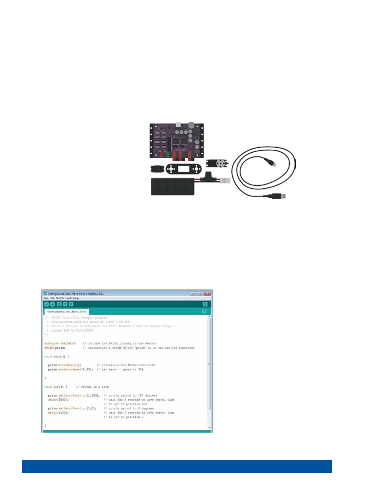
Activity 3: Moving Your Servo Motors
Our third activity will explore another element of motion with servo motors. We will
create a sketch to rotate a servo motor.
Servo motors offer the benefit of being able to move to a set position regardless
of the start position within a limited range of motion. Servo motors have an
approximate range of motion from 0 to 180 degrees. For example, we can tell
a servo to go to position 45 degrees regardless of where it starts. If it starts at 0
degrees, it will move clockwise to 45 degrees. If it starts at 120 degrees, it will move
counterclockwise to 45 degrees.
Parts Needed
• 180-Degree Standard-Scale HS-485HB
Servo Motor
• PRIZM controller
• USB cable
• A charged TETRIX 12-Volt Rechargeable
NiMH Battery Pack
• PRIZM Controller On/Off Battery Switch
Adapter
• Computer
Opening the Sketch
Before we open our next example sketch, be sure to save any sketch you want to
reference later.
Open the sketch by selecting File>Examples>TETRIX_PRIZM>GettingStarted_
Act3_Move_Servo. A new sketch window will open titled GettingStarted_Act3_
Move_Servo (Figure 12).
Figure 12
22 Getting Started Activities

Building the Knowledge Base
In this third sketch we want to continue looking at sketch syntax, specifically the
include statement and the object declaration. The include statement is used to
add the functionality of the PRIZM software library into the sketch. The object
declaration is a technique used when writing programs to make them easier to
manage as they grow in size and complexity.
The PRIZM software library is a collection of special mini programs each with its
own distinct function name. These mini programs are designed to make writing
sketches for PRIZM easy and intuitive. By using the include statement, we add
the functionality of the library to our sketch. The include statement for PRIZM is
#include <PRIZM.h>.
The object declaration is an important statement when using the PRIZM controller
along with the PRIZM software library. In order to use the functions contained in
the PRIZM software library, we must first declare a library object name that is then
inserted as a “prefix” before each library function. The object declaration we use is
PRIZM prizm;. We use this statement just after the include statement.
In all of our sketch examples, we use an include statement and object declaration to
add the functionality of the PRIZM software library. Include statements and object
declarations are common for most forms of C-based language.
Executing the Code
Before we can upload the sketch to the PRIZM, remember to check our connections.
Keep in mind that we added a new connection with the servo motor.
Upload the sketch. The green LED will light up, indicating the code is ready to
execute. When this has happened, press the green Start button on the PRIZM
controller.
Observe the direction and duration of the servo motor rotation. Based on the
sketch comments, did the behavior match expectations?
Press the red Reset button when you are ready to stop the motor.
Getting Started Activities 23

Moving Forward
In this sketch we introduce two new PRIZM functions, prizm.setServoSpeed and
prizm.setServoPosition. Both functions have two parameters, but they are different.
The two parameters of the prizm.setServoSpeed function are servo channel and
servo speed. In the example, prizm.setServoSpeed(1,25) means servo 1 will spin at
25% power while it rotates to the position commanded by the
prizm.setServoPosition function. This function needs to be called only once at the
beginning of the program.
The two parameters of the prizm.setServoPosition function are servo channel and
target position. In the example, prizm.setServoPosition(1,180) means servo 1 will
rotate to the target position of 180 degrees.
In the sketch both of these functions work together to tell the servo motor not only
the target position but also the speed to use while moving to the target position.
We can alter the position and speed of the servo by changing the values of both
functions.
For more detailed information about the sketch process and the PRIZM library
functions involved in moving the servo motor, refer to the following section within
the appendix: TETRIX PRIZM Arduino Library Functions:
• Pages 144-145 about servo motor functions
Practice changing the parameters in the sketch. Observe the effect these changes
have on the servo motor.
Tip: Remember that you
can print and use the TETRIX
PRIZM Arduino Library
Functions Cheat Sheet within
the appendix on page 153 as
a quick reference for all the
functions available to you.
Tip: Want to see this in
action? You can by watching
our RoboBench video series
for the PRIZM Programming
Guide. You can find the
entire series at video.
tetrixrobotics.com or on
the TETRIXrobotics YouTube
channel.
Real-World Connection
Historically, servo motors were used mostly with a remote-controlled (R/C)
transmitter for R/C model cars to control steering or R/C model airplanes to control
flaps and rudders. Robots can use servos controlled by R/C transmitters – but they
can also use servos controlled by PRIZM to operate robotic arms, grippers, tilting
and rotating mounts for cameras, or many other applications in which precise
movement is needed.
STEM Extensions
Science
• Levers
• Centripetal force
Technology
• Mechanical linkages
• Transmission of force
Engineering
• Applying torque
Math
• Radian vs Cartesian measurements
• Arc length
Hacking the Code Activity
With the example as a reference, try creating a new sketch to move your servo
motor. Remember what we learned from our previous activities and think of
creative ways to combine the functions you have learned.
Tip: In the sketch window
the PRIZM library functions
change color when they
are typed or spelled
correctly. Consequently,
if spelled incorrectly they
will not change. In Arduino,
the PRIZM functions are
recognized by the software
as keywords and will turn
orange when the syntax is
correct.
Tip: An example library of
code to help you get started
with this challenge can be
found in the appendix. If you
have a digital copy of this
guide, you can simply copy
and paste the sample code
for each activity into your
sketch window. A digital
download can be found at
www.TETRIXrobotics.com/
PRIZMdownloads.
24 Getting Started Activities

Activity 4: Introduction to the Line Finder Sensor
For the fourth activity we will change focus from motor outputs to sensor inputs
by introducing and exploring sensors. In this example we will connect a Line Finder
Sensor to digital sensor port D3, and we will create a sketch to read a digital input
from the Line Finder Sensor.
Sensors enable us to gather information from the world around us. The type of
information depends on the type of sensor. The Line Finder Sensor uses reflected
infrared light to distinguish between light and dark surfaces.
Parts Needed
• Contrasting light and dark surface
• Grove Line Finder Sensor and cable
• PRIZM controller
• USB cable
• A charged TETRIX 12-Volt
Rechargeable NiMH Battery Pack
• PRIZM Controller On/Off Battery
Switch Adapter
• Computer
Figure 13: Contrasting light and dark surface
Opening the Sketch
Before we open our next example sketch, be sure to save any sketch you want to
reference later.
Open the sketch by selecting File > Examples > TETRIX_PRIZM >
GettingStarted_Act4_Intro_LineFinder. A new sketch window will open titled
GettingStarted_Act4_Intro_LineFinder (Figure 14).
Figure 14
Getting Started Activities 25

Building the Knowledge Base
For the fourth sketch we want to take a closer look at two of the fundamental
structure elements that make up a sketch. In every sketch you write, there will be a
setup() and a loop() function.
The setup() function follows right after the include statement and object
declaration as part of the beginning of our code. The setup() function contains
items that need to be run only once as part of the sketch. Many functions can
go here, but we always use at least the PRIZM initialization statement, prizm.
PrizmBegin(). The main purpose of this function is to configure the Start button.
The loop() function does exactly what its name suggests. Everything contained
within the brackets of the loop will repeat consecutively until the sketch is ended
with a command or the Reset button. The loop() contains the main body of our
code.
The contents of the setup() and the loop() are contained between curly braces.
A left curly brace { begins a group of statements, and a right curly brace } ends
a group of statements. They can be thought of as bookends, and the code in
between is said to be a block of code.
26 Getting Started Activities

Executing the Code
Before we can upload the sketch to the PRIZM, remember to check our connections.
Keep in mind that we added a new connection in digital sensor port 3 with the Line
Finder Sensor.
Upload the sketch. The green LED will light up indicating the code is ready to
execute. When this has happened, press the green Start button on the PRIZM
controller.
Hold the sensor over the contrasting surface. As the sensor moves from light
to dark, observe the red LED on the PRIZM. When the sensor is over a line, nonreflective, or dark surface, the red LED will be off. When the sensor is over a white or
reflective surface, the red LED will be on.
Press the red Reset button when you are ready to stop the sensor.
Moving Forward
This sketch introduces a program structure, a new function, and a comparison
statement. The program structure is an “if” statement, the new function is
prizm.readLineSensor, and the comparison statement is == (equal to).
Note: The Line Finder Sensor
has an adjustable range that
we can tweak by turning the
small adjustment screw on
the back side of the sensor
board.
Tip: Remember that you
can print and use the TETRIX
PRIZM Arduino Library
Functions Cheat Sheet within
the appendix on page 153 as
a quick reference for all the
functions available to you.
The basic “if” statement enables us to test for a certain condition. If this condition is
met, then the program can perform an action. If the statement in the parentheses
is true, the statements within brackets are run; if the statement is not true, the
program will skip over the code.
The function prizm.readLineSensor reads the state of the Line Finder Sensor
and returns a value of “1” (HIGH) or “0” (LOW). A value of “1” is returned when the
Line Finder Sensor detects a dark line or a non-reflective surface; a value of “0” is
returned when the Line Finder Sensor detects a white or reflective surface.
The comparison statement == (equal to) defines a type of test.
When these three elements are combined in the sketch, we create a test condition
based on the input of the Line Finder Sensor that turns the red LED on or off. In
simple terms, if the Line Finder Sensor detects a line or a non-reflective surface,
then it turns the red LED off. If the Line Finder Sensor detects a white or reflective
surface, it turns the LED on.
For more detailed information about the sketch process and the PRIZM library
functions involved in using the Line Finder Sensor, refer to the following section
within the appendix: TETRIX PRIZM Arduino Library Functions:
• Pages 134-135 about sensor port functions
Experiment with the Line Finder Sensor on different surfaces and different heights
to see how the sensor reacts.
Tip: Want to see this in
action? You can by watching
our RoboBench video series
for the PRIZM Programming
Guide. You can find the
entire series at video.
tetrixrobotics.com or on
the TETRIXrobotics YouTube
channel.
Getting Started Activities 27

Real-World Connection
Finding our way in this world can be challenging. Telling a robot how to find its
way can be challenging as well. One way that robots within a warehouse can find
their way to the right location is by having them follow lines. But to follow lines,
they have to detect the lines. One way to accomplish this is by using a sensor
that detects dark and light surfaces. This, through the computer code, provides
information to the robot about where the line is. Other code controls the DC
motors to change course if the robot strays from the line.
STEM Extensions
Science
• Light – reflection and absorption
• Electromagnetic spectrum
Technology
• Digital vs analog
• Calibration
Engineering
• Determining an edge location
Math
• Data analysis
Hacking the Code Activity
With the example as a reference, try creating a new sketch to use your Line Finder
Sensor. Remember what we learned from our previous activities, and think of
additional creative actions to perform based on the condition of the Line Finder
Sensor.
Tip: In the sketch window
the PRIZM library functions
change color when they
are typed or spelled
correctly. Consequently,
if spelled incorrectly they
will not change. In Arduino,
the PRIZM functions are
recognized by the software
as keywords and will turn
orange when the syntax is
correct.
Tip: An example library of
code to help you get started
with this challenge can be
found in the appendix. If you
have a digital copy of this
guide, you can simply copy
and paste the sample code
for each activity into your
sketch window. A digital
download can be found at
www.TETRIXrobotics.com/
PRIZMdownloads.
28 Getting Started Activities

Activity 5: Introduction to the Ultrasonic Sensor
For the final getting started activity, we will finish up our exploration of sensors
by creating a sketch using the Ultrasonic Sensor. In this activity we will connect an
Ultrasonic Sensor to digital sensor port D3 and display the distance to an object we
place in front of it using the serial monitor window.
Like all sensors, the Ultrasonic Sensor enables us to gather information. For the
Ultrasonic Sensor, the information gathered communicates distance. The sensor
works by sending a sonic pulse burst and then waiting on its return to the sensor
as it is reflected off an object in range. The reflected sonic pulse time period is
measured to determine the distance to the object. The sensor has a measuring
range of approximately 3-400 centimeters.
Parts Needed
• Grove Ultrasonic Sensor and cable
• PRIZM controller
• USB cable
• A charged TETRIX 12-Volt
Rechargeable NiMH Battery Pack
• PRIZM Controller On/Off Battery
Switch Adapter
• Computer
Opening the Sketch
Before we open our next example sketch, be sure to save any sketch you want to
reference later.
Open the sketch by selecting File > Examples > TETRIX_PRIZM >
GettingStarted_Act5_Intro_UltraSonic. A new sketch window will open titled
GettingStarted_Act5_Intro_UltraSonic (Figure 15).
Figure 15
Getting Started Activities 29

Building the Knowledge Base
For our fifth sketch of the getting started activities, we want to look at a useful tool
for viewing data as a dynamic text output. The serial monitor displays serial data
being sent from the PRIZM via the USB connection.
The serial monitor’s value as a tool lies in its ability to display data in real time that
enables you to make better-informed design decisions about robot builds and
programming. It can be used to display data from sensors connected to PRIZM or
to examine any program data collected by the PRIZM – for example, encoder count
data, DC motor current data, or servo position data.
Executing the Code
Before we can upload the sketch to the PRIZM, remember to check our connections.
Keep in mind that we added a new connection in digital sensor port 3 with the
Ultrasonic Sensor.
Upload the sketch. Before we execute the sketch, we need to open the serial
monitor from the sketch window. To open the serial monitor, click the magnifying
glass in the top-right corner of the sketch window (Figure 16).
Figure 16
The serial monitor will open in a separate window (Figure 17).
Figure 17
With the sensor lying flat on the desk pointed up, press the green Start button to
execute the code.
30 Getting Started Activities

Hold an object above the sensor at varying distances and observe the serial
monitor to see the real-time data.
Press the red Reset button when you are ready to stop the sensor.
Moving Forward
This sketch introduces several new functions: Serial.begin(), Serial.print(),
prizm.readSonicSensorCM(), and Serial.println().
Serial.begin() enables the use of serial communication within the sketch. As an
initialization function that needs to be run only once, it belongs in the setup of the
sketch. An important part of Serial.begin() is the speed of communication in bits
per second, which is called baud rate. The default setting for baud rate in the serial
window is 9600, so that is what we use in Serial.begin().
Tip: Remember that you
can print and use the TETRIX
PRIZM Arduino Library
Functions Cheat Sheet within
the appendix on page 153 as
a quick reference for all the
functions available to you.
Tip: Want to see this in
action? You can by watching
our RoboBench video series
for the PRIZM Programming
Guide. You can find the
entire series at video.
tetrixrobotics.com or on
the TETRIXrobotics YouTube
channel.
Figure 18
Serial.print() prints data to the serial port as readable text. This can take the
form of dynamic information from another device or static information from the
programmer.
prizm.readSonicSensorCM() reads the state of the Ultrasonic Sensor and returns a
digital value within the designated measurement range. For our sensor, that range
is between approximately 3-400 centimeters. This value should reflect the distance
the Ultrasonic Sensor is from a detectable object.
Serial.println() prints data to the serial port as readable text followed by a built-in
command for a new line.
These four functions might seem complicated, but they actually work together
simply. In this sketch, Serial.begin(9600) enables and defines the speed of
communication in the setup. Serial.print() tells what type of data to print.
prizm.readSonicSensorCM() provides the type of data to print because it is within
the parentheses of Serial.print(). And Serial.println(“ Centimeters”) clarifies the type
of data being printed – in this case, with the modifier “ Centimeters.”
Figure 19
Getting Started Activities 31

For more detailed information about the sketch process and the PRIZM library
functions involved in using the Ultrasonic Sensor and the serial monitor, refer to
www.arduino.cc and the appendix: TETRIX PRIZM Arduino Library Functions:
• Pages 134-135 about sensor port functions
Real-World Connection
When you were very, very young, you were probably scanned by an ultrasonic
sensor. If you do not remember this, it is because it was prior to you being born.
One of the great applications of ultrasonic technology is within the medical field.
Doctors can use the reflection of sound waves back to sensor waves to see inside
a living person. Doctors can see a baby’s size and development – and determine
when they think he or she might be born!
STEM Extensions
Tip: In the sketch window
the PRIZM library functions
change color when they
are typed or spelled
correctly. Consequently,
if spelled incorrectly they
will not change. In Arduino,
the PRIZM functions are
recognized by the software
as keywords and will turn
orange when the syntax is
correct.
Science
• Sound wave terminology (frequency, amplitude, crest, trough)
• Reflection of sound waves
Technology
• Measuring frequency
• Sound digitization
Engineering
• Applications of sonic measurements
Math
• Inverse square law
Hacking the Code Activity
With the example as a reference, try creating a new sketch to use the Ultrasonic
Sensor with the serial monitor. Remember what we learned from our previous
activities and experiment with different objects in front of the Ultrasonic Sensor to
see if they are detectable and if the distances can be measured accurately.
Try changing the code for prizm.readSonicSensorCM() to prizm.readSonicSensorIN()
to display the distance from an object in inches. Also be sure to change the Serial.
printIn from “ Centimeters” to “ Inches” so that the unit is correctly labeled in the
serial monitor window. Understanding how to use the Ultrasonic Sensor will give
your robot vision to be able to steer around objects and obstacles.
Tip: An example library of
code to help you get started
with this challenge can be
found in the appendix. If you
have a digital copy of this
guide, you can simply copy
and paste the sample code
for each activity into your
sketch window. A digital
download can be found at
www.TETRIXrobotics.com/
PRIZMdownloads.
32 Getting Started Activities

Building and Coding the PRIZM TaskBot
This is what you have been waiting for. It is time to move to the next level. You
have worked hard to learn the basics, and now it is time to apply them to an
actual robot. The next 10 activities will walk us through building a robot, basic
movement, navigation, adding sensors, and more, culminating in an activity
that combines everything. It is about to get exciting.
Getting Started Activities 33

Programmable Robotics Set
Note: In order to complete the activities shown in this book, you must have the TETRIX MAX Programmable Robotics Set.
34 Building and Coding the PRIZM TaskBot

TETRIX MAX Programmable Robotics Set Parts Index
Servos & Hardware
Channels
Part No. Part Name Quantity
39065 TETRIX® MAX 32 mm Channel ...............................6
39066 TETRIX® MAX 96 mm Channel ...............................4
39067 TETRIX® MAX 160 mm Channel ..............................4
39068 TETRIX® MAX 288 mm Channel ..............................4
Bars & Angles
Part No. Part Name Quantity
39070 TETRIX® MAX 288 mm Flat Bars ..............................2
39072 TETRIX® MAX 144 mm Angle .................................2
39071 TETRIX® MAX 288 mm Angle .................................2
Plates & Brackets
Part No. Part Name Quantity
39073 TETRIX® MAX Flat Building Plates ............................2
39061 TETRIX® MAX Flat Brackets ...................................6
39062 TETRIX® MAX L Brackets ......................................6
39281 TETRIX® MAX Inside Corner Brackets .........................6
39270 TETRIX® MAX Inside C Connectors ...........................6
41790 TETRIX® MAX Adjustable Angle Corner Bracket ..............4
Flats
Part No. Part Name Quantity
39274 TETRIX® MAX Flat 64 mm x 16 mm ...........................2
39273 TETRIX® MAX Flat 96 mm x 16 mm ...........................2
39272 TETRIX® MAX Flat 160 mm x 16 mm .........................2
39271 TETRIX® MAX Flat 288 mm x 16 mm .........................2
41791 TETRIX® MAX Adjustable Angle Flat Bracket .................6
Part No. Part Name Quantity
39060 TETRIX® MAX Single Standard-Scale Servo Motor Bracket ...1
39593 TETRIX® MAX Standard-Scale Pivot Arm with Bearing ........1
39197 180° Standard-Scale HS-485HB Servo Motor .................2
39081 Servo Extension ..............................................2
39082 Ser vo Y Connec tor ...........................................1
41789 TETRIX® MAX Standard Servo Mounting Kit ..................2
39280 TETRIX® MAX Adjustable Servo Brackets .....................2
DC Motors & Hardware
Part No. Part Name Quantity
39089 TETRIX® MAX Motor Mount ..................................2
39530 TETRIX® MAX DC Gear Motor ................................2
Tires & Wheels
Part No. Part Name Quantity
39055 TETRIX® MAX 4" Wheel .......................................2
36466 TETRIX® MAX 4" Omni Wheel ................................2
Nuts, Screws, & Fasteners
Part No. Part Name Quantity
39094 Kep Nuts ..................................................100
39097 Socket Head Cap Screws 6-32 x 1/2" ......................100
39098 Socket Head Cap Screws 6-32 x 5/16" .....................100
39111 Button Head Cap Screw 3/8" ............................... 50
31902 Zip Ties ..................................................... 12
Axles, Hubs, & Spacers
Part No. Part Name Quantity
39079 TETRIX® MAX Motor Hub .....................................2
39172 TETRIX® MAX Axle Hubs. . . . . . . . . . . . . . . . . . . . . . . . . . . . . . . . . . . . . .6
39092 TETRIX® MAX Axle Set Collars ................................6
39088 TETRIX® MAX 100 mm Axles .................................6
39091 TETRIX® MAX Bronze Bushings ............................. 24
39090 TETRIX® MAX Gear Hub Spacers .............................2
39100 TETRIX® MAX Axle Spacers 1/8" ............................ 12
39101 TETRIX® MAX Axle Spacers 3/8" ..............................6
39387 TETRIX® MAX Flat Round Spacer .............................6
Gearing
Part No. Part Name Quantity
39028 TETRIX® MAX Gear 40-Tooth .................................4
39086 TETRIX® MAX Gear 80-Tooth .................................4
Posts & Standos
Part No. Part Name Quantity
39102 TETRIX® Stand-O Post 6-32 x 1" ..........................12
39103 TETRIX® Stand-O Post 6-32 x 2" ..........................12
39107 TETRIX® Stand-O Posts 6-32 x 32 mm ..................... 12
41253 TETRIX® Stand-O Posts 6-32 x 16 mm ..................... 12
Battery & Charger
Part No. Part Name Quantity
38009 TETRIX® MAX Battery Clips ...................................2
39057 TETRIX® MAX 12-volt 3,000 mAh Battery .....................1
39830 TETRIX® MAX 12-volt Battery Charger ........................1
Tools
Part No. Part Name Quantity
36404 4-in-1 Screwdriver ...........................................1
38001 TETRIX® Wrench Set ..........................................2
39104 TETRIX® MAX Hex Key Pack ..................................4
40341 Miniature Ball-Point Hex Driver ..............................1
42991 2-in-1 Screwdriver . . . . . . . . . . . . . . . . . . . . . . . . . . . . . . . . . . . . . . . . . . . 1
Electronics & Control
Part No. Part Name Quantity
43000 PRIZM controller .............................................1
41352 TETRIX Motor Cable with Powerpoles ........................2
43169 PRIZM Controller On/O Battery Switch Adapter ............1
43056 Line Finder Sensor Pack ...................................... 1
43055 Ultrasonic Sensor Pack .......................................1
40967 3-foot Type A-B USB Cable ...................................1
Building and Coding the PRIZM TaskBot 35

TETRIX MAX Hardware Components Overview
The following mechanical parts overview includes elements from the TETRIX MAX Programmable Robotics Set.
Channels
TETRIX MAX structural elements are identified by length. For example, a 32 mm Channel or a 288 mm Flat Bar. Use the
inches ruler below to measure stand-off posts and wheels. Use the centimeters ruler at the bottom of this spread to
measure part lengths.
Structural Elements
32 mm Channel 39065
96 mm Channel 39066
160 mm Channel 39067
288 mm Channel 39068
36 Building and Coding the PRIZM TaskBot

Structural Elements
Flat Bracket 39061
288 mm Flat Bar 39070
144 mm Angle 39072
288 mm Angle 39071
Flat Building Plate 39073
L Bracket 39062
Inside Corner Bracket 39281
Inside C Connector 39270
Adjustable Angle Corner Bracket 41790
Building and Coding the PRIZM TaskBot 37

Structural Elements
Flat 64 mm x 16 mm 39274
Flat 96 mm x 16 mm 39273
Flat 160 mm x 16 mm 39272
Flat 288 mm x 16 mm 39271
Adjustable Angle Flat Bracket 41791
Flat Round Spacer 39387
Stand-Off Post 6-32 x 1" 39102
Stand-Off Post 6-32 x 2" 39103
Stand-Off Post 6-32 x 32 mm 39107
Stand-Off Post 6-32 x 16 mm 41253
38 Building and Coding the PRIZM TaskBot

Motion Elements
Gear 40-Tooth 39028
Gear 80-Tooth 39086
Gear 120-Tooth 39085
Axle Hub 39172
Motor Hub 39079
Axle Set Collar 39092
100 mm Axles 39088
Bronze Bushing 39091
Gear Hub Spacer 39090
Axle Spacer 1/8" 39100
Axle Spacer 3/8" 39101
Building and Coding the PRIZM TaskBot 39

Motion Elements
Motor Mount 39089
DC Gear Motor 39530
4" Wheel 39055
4" Omni Wheel Pack/Assembly 36466
Kep Nut 39094
Socket Head Cap Screw 6-32 x 1/2" 39097
Socket Head Cap Screw 6-32 x 5/16" 39098
Button Head Cap Screw 3/8" 39111
40 Building and Coding the PRIZM TaskBot

Motion Elements
Single Standard-Scale Servo Motor Bracket 39060
Standard-Scale Pivot Arm with Bearing 39593
180° Standard-Scale HS-485HB Servo Motor 39197
Servo Extension 39081
Servo Y Connector 39082
Standard Servo Mounting Kit 41789
Adjustable Servo Bracket 39280
Building and Coding the PRIZM TaskBot 41

Power, Tools, and Accessories Elements
Battery Clip 38009
12-volt 3,000 mAh Battery 39057
12-volt Battery Charger 39830
2-in-1 Screwdriver 42991
4-in-1 Screwdriver 36404
Wrench Set 38001
Hex Key Pack 39104
Miniature Ball-Point Hex Driver 40341
Zip Tie 31902
42 Building and Coding the PRIZM TaskBot

Control Elements
PRIZM™ Controller 43000
TETRIX Motor Cable with Powerpoles 41352
PRIZM Controller On/Off Battery Switch Adapter 43169
3 foot Type A-B USB Cable 40967
Line Finder Sensor Pack 43056
Ultrasonic Sensor Pack 43055
Building and Coding the PRIZM TaskBot 43

PRIZM™ Controller Wiring Illustrated
Detail
44 Building and Coding the PRIZM TaskBot

TETRIX MAX Builder’s Guide Setup/Construction Tips
Planning for easy access to fasteners will make the building experience better for everyone involved.
As a general rule, when you create any substructure, it’s a good idea to only snug nuts and screws until you are sure all
elements fit together. Then, go back and tighten everything before moving on to the next step.
1. Channel Placement
A little planning and forethought about how structural elements go together can make your building experience easier,
quicker, and more efficient.
In the figure above, both structures have similar building surfaces to work from but have different accessibility for
fastening the Kep Nuts on the screws. Easy access is preferred. Avoid difficult access if possible.
Building and Coding the PRIZM TaskBot 45

2. Tool Use
Proper use of the basic tools makes the building process smoother and more enjoyable and saves time.
46 Building and Coding the PRIZM TaskBot

3. Take Advantage of Design Features
Some elements have design features that either make the element function better or fill a specific role. Recognizing those
so you can take full advantage will make your build be stronger, last longer, and function better.
This is the proper orientation for Kep Nuts. The self-locking feature of the Kep Nut should always be against the flat surface
of the structural element, such as in the example on the left. The image on the right is wrong!
Below is a view of both together for comparison.
The orientation of the Kep Nut on the left is correct.
The orientation of the Kep Nut on the right is wrong!
Using the right-length screw for the job will make best
use of your available resources. Use the shortest screw
possible to get the job done, and save the longer screws
for the places where they are necessary.
While either screw in the image above would
work, the best use of resources would dictate
using the one shown on the right.
Building and Coding the PRIZM TaskBot 47

Axle Hubs and Motor Hubs are often confused because they look alike and they serve the same function but in slightly
different applications.
The difference between the two elements is the size of the inside diameter of the hole in the center of the element. The
Axle Hub is sized for the axle, while the Motor Hub is sized for the motor shaft.
While Axle Hubs can be used only on axles because of size, the Motor Hub could be incorrectly used on an axle and cause
problems with function and attachment of wheels or gears. The image on the left shows an axle in the center of a Motor
Hub. Notice the difference in size between the outer diameter of the axle and the inside diameter of the Motor Hub. The
image on the right shows an axle in the center of the Axle Hub. Notice the elements are sized correctly to fit together and
function properly.
48 Building and Coding the PRIZM TaskBot

4. Assembly of Specialty Parts
Omni Wheel Setup Parts Needed
2x
4" Omni Wheel Pack/
Assembly 36466
1x
Omni Wheel
Spacer 36466
2x
Bronze Bushings
39091
Step 1.0
Step 1.1 (front view) Step 1.1 (back view)
4x
Button Head Cap
Screw 3/8" 39111
Building and Coding the PRIZM TaskBot 49

Step 1.2 Step 1.3
Tip: To get proper offset of rollers
between the two wheels, remove
screws from Step 1.3 and rotate the
wheel shown in either direction.
Reattach screws.
50 Building and Coding the PRIZM TaskBot

Activity 6: Build the TaskBot
We need a robot. Because the focus of this guide is on working with PRIZM and the
Arduino Software (IDE), we do not need a complicated robot. With that in mind, we
created the PRIZM TaskBot. The TaskBot is meant to be simple, easy to build, and
exactly what we need for the purposes of this guide without any unnecessary parts.
That being said, everything you learn with this basic bot can be transferred to a
more complicated bot as you continue on your robotics journey.
The TaskBot uses two 12-volt motors mounted back to back for a good example of a
differential-drive robot. Two omni wheel assemblies on the opposite end combined
with the maneuverable drive make a perfect test vehicle for our work with PRIZM.
We will start with a basic drive frame and add more to it in later activities.
This build should be perfect for students who have little to no experience with
metal-based building systems.
Building Time Expectations
45-55 minutes
Teacher note: Many factors
can affect building time,
including such things as set
organization and whether
the builder has a partner.
The above time is only an
estimate and is based on
an individual builder of
average experience who is
comfortable with hands-on
building activities and has
access to complete, wellorganized sets. Actual time
might vary.
Real-World Connection
The construction of a machine will determine its effectiveness as well as its
durability. Engineers design machines (including robots) for specific purposes. For
instance, a bulldozer is built from very strong and durable materials to be able to
withstand the forces involved in pushing over trees and buildings or digging out
large holes in the ground.
STEM Extensions
Science
• Structure and function
Technology
• Materials
• Fasteners
Engineering
• Machine design
Math
• Measurement
• Modulus
Building and Coding the PRIZM TaskBot 51

Step 1
Parts Needed
8x
Socket Head Cap Screw
6-32 x 5/16" 39098
4x
288 mm Channel 39068
Tip: See page 36 for help with identifying Channel elements. Remember, we identify by length.
Partial assembly should look like this.
8x
Kep Nut 39094
52 Building and Coding the PRIZM TaskBot

Step 1.0
Step 1.1
Tip: It’s a good idea to only snug the
nuts and screws until all four Channels
are connected.
Building and Coding the PRIZM TaskBot 53

Step 1.2
Step 1.3
54 Building and Coding the PRIZM TaskBot

Rotate build to match this view.
Step 1.4
Building and Coding the PRIZM TaskBot 55

Step 1.5
Step 1.6
Tip: After all four Channels are connected and
the square frame is created, don’t forget to go
back and tighten all the screws and nuts.
56 Building and Coding the PRIZM TaskBot

Step 2
Parts Needed
8x
Kep Nut
2x
L Bracket 39062
4x
Socket Head Cap Screw
6-32 x 1/2" 39097
Socket Head Cap Screw
Partial assembly should look like this.
39094
4x
6-32 x 5/16" 39098
1x
PRIZM Controller On/Off Battery
Switch Adapter 43169
Building and Coding the PRIZM TaskBot 57

Rotate build to match this view.
Step 2.0
58 Building and Coding the PRIZM TaskBot
Step 2.1
Rotate build to match this view.
Building and Coding the PRIZM TaskBot 59

Step 2.2
Tip: This step uses Socket Head Cap
Screws (39097).
Tip: It does not matter in which direction the On/Off Power Switch is mounted in the
plate. It is strictly a matter of personal preference.
Step 2.3
60 Building and Coding the PRIZM TaskBot

Step 3
Parts Needed
2x
4" Omni Wheel Pack/Assembly
36466
4x
Bronze Bushing 39091
Socket Head Cap Screw
6-32 x 5/16" 39098
6x
Partial assembly should look like this.
2x
32 mm Channel
39065
2x
100 mm Axle
39088
6x
Kep Nut 39094
4x
Axle Set Collar
39092
2x
Axle Spacer 1/8" 39100
Building and Coding the PRIZM TaskBot 61

Step 3.0
Step 3.1
62 Building and Coding the PRIZM TaskBot

Step 3.2
Step 3.3
Building and Coding the PRIZM TaskBot 63

Step 3.4
Step 3.5
Tip: Refer to Omni Wheel Setup
on pages 49-50 to see how to
assemble the Omni Wheel.
64 Building and Coding the PRIZM TaskBot

Step 3.6
Step 3.7
Building and Coding the PRIZM TaskBot 65

Step 3.8
66 Building and Coding the PRIZM TaskBot

Step 4
Parts Needed
2x
4" Wheel 39055
2x
Motor Hub 39079
Finished assembly should look like this.
2x
Motor Mount 39089
8x
Socket Head Cap Screw
6-32 x 1/2" 39097
2x
DC Gear Motor 39530
4x
Kep Nut 39094
Tip: See the setup tips on page 48 for help distinguishing between the Motor Hub and Axle Hub.
Building and Coding the PRIZM TaskBot 67

Step 4.0
Tip: The screw over the split end of the motor
mount holds the motor in position inside the
mount. To insert the motor and move it into
position, you must keep the screw loose. Don’t
forget to go back and tighten this screw after
the motor has been inserted and moved into the
desired position.
Step 4.1
68 Building and Coding the PRIZM TaskBot

Step 4.2
Step 4.3
Tip: This step uses the
Motor Hub (39079).
Don’t forget to tighten
the set screw.
Building and Coding the PRIZM TaskBot 69

Step 4.4
Step 4.5
Tip: The screw over the split end of the motor
mount holds the motor in position inside the
mount. To insert the motor and move it into
position, you must keep the screw loose. Don’t
forget to go back and tighten this screw after
the motor has been inserted and moved into the
desired position.
70 Building and Coding the PRIZM TaskBot

Step 4.6
Step 4.7
Building and Coding the PRIZM TaskBot 71
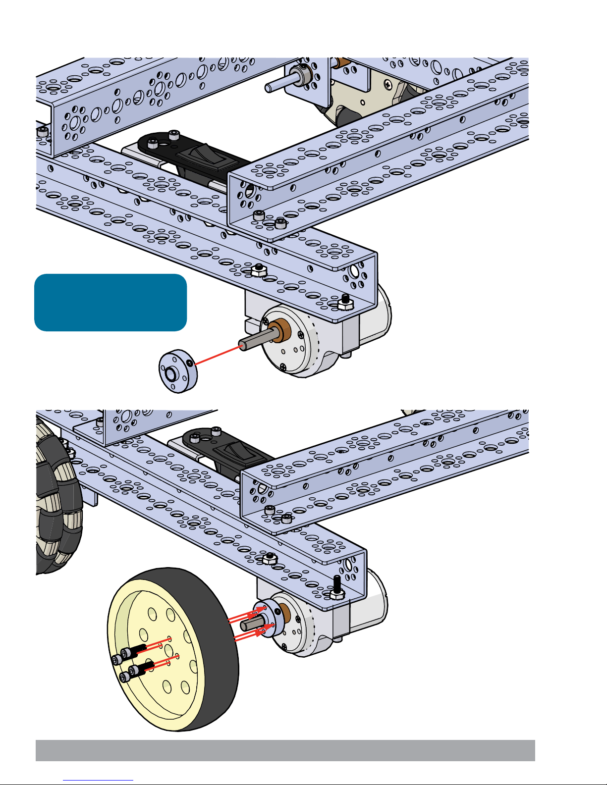
Step 4.8
Tip: This step uses the Motor
Hub (39079). Don’t forget to
tighten the set screw.
Step 4.9
72 Building and Coding the PRIZM TaskBot

Step 5
Parts Needed
1x
12-volt 3,000 mAh Battery 39057
1x
Flat 160 mm x 16 mm
39272
Stand-Off Post 6-32 x 1"
Finished assembly should look like this.
8x
39102
2x
Flat Building Plate 39073
2x
Battery Clip 38009
16x
Socket Head Cap Screw
6-32 x 5/16" 39098
Building and Coding the PRIZM TaskBot 73
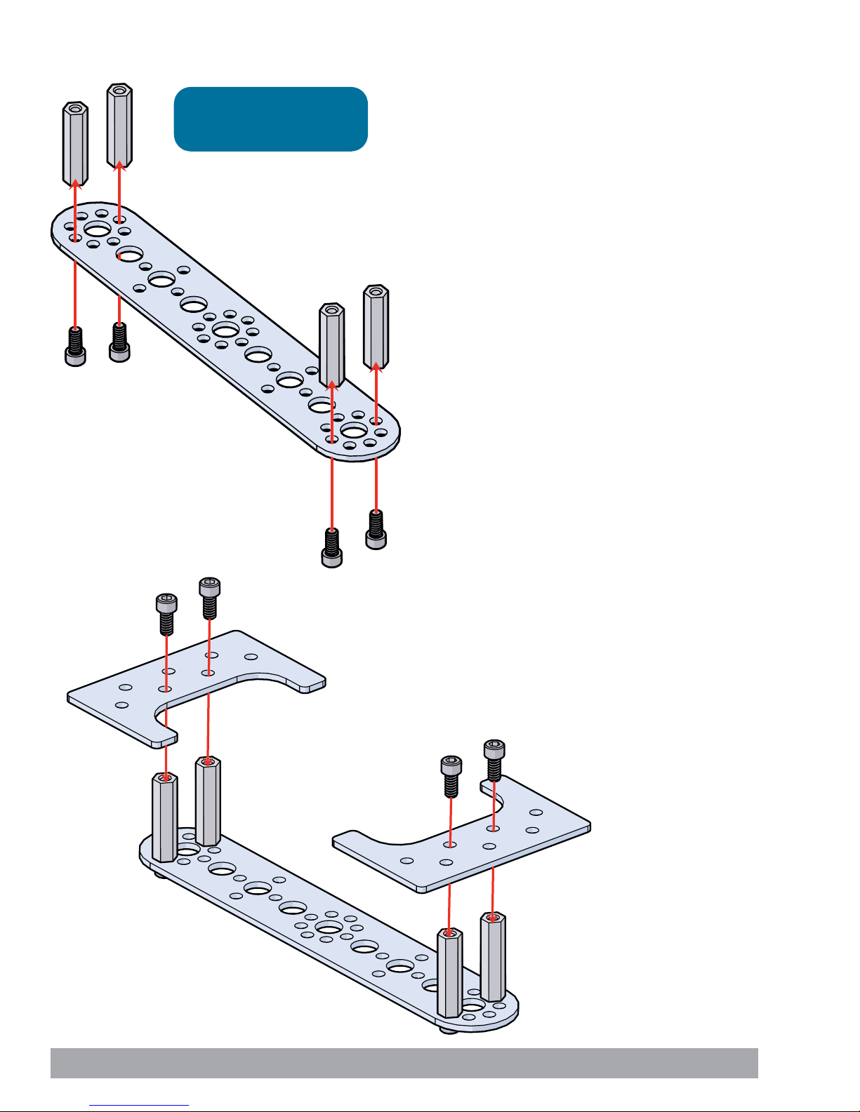
Step 5.0
Tip: This step uses 6-32 x 1"
Stand-Off Posts (39102).
Step 5.1
74 Building and Coding the PRIZM TaskBot

Step 5.2
Tip: This step uses 6-32 x 1"
Stand-Off Posts (39102).
Step 5.3
Building and Coding the PRIZM TaskBot 75

Step 5.4
Step 5.5
76 Building and Coding the PRIZM TaskBot

Step 6
Parts Needed
8x
Socket Head Cap Screw
6-32 x 5/16" 39098
Finished assembly should look like this.
8x
Kep Nut 39094
Building and Coding the PRIZM TaskBot 77

Step 6.0
Step 6.1
78 Building and Coding the PRIZM TaskBot

Step 6.2
Step 6.3
Building and Coding the PRIZM TaskBot 79

Step 7
Parts Needed
1x
PRIZM controller 43000
Finished assembly should look like this.
4x
Socket Head Cap Screw
6-32 x 1/2" 39097
4x
Kep Nut 39094
80 Building and Coding the PRIZM TaskBot
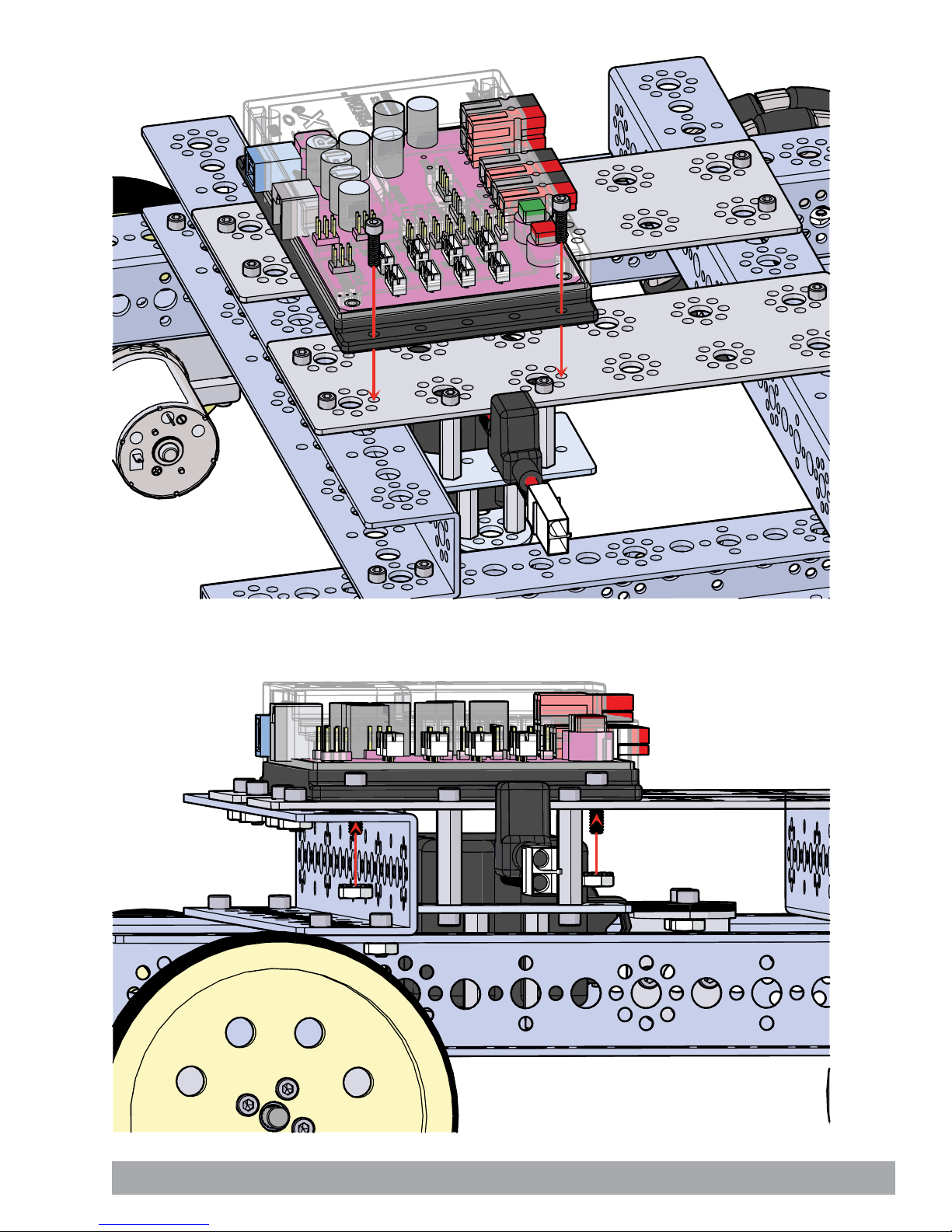
Step 7.0
Step 7.1
Building and Coding the PRIZM TaskBot 81

Step 7.2
Step 7.3
82 Building and Coding the PRIZM TaskBot

Finished assembly should look like this.
Building and Coding the PRIZM TaskBot 83

Activity 7: Drive Forward
Activity 7 is the first activity with the TaskBot. We want to start with something
simple. In this activity we will create a sketch to move the TaskBot forward for three
seconds, stop, and end the program.
Building on what we learned in Activity 2, we will add a second motor and have
them work together in unison. Being able to use two motors together in unison is a
fundamental requirement for mobile robots.
Parts Needed
• Fully assembled PRIZM TaskBot
• USB cable
• A charged TETRIX 12-Volt Rechargeable
NiMH Battery Pack
• Computer
Opening the Sketch
Before we open our next example sketch, be sure to save any sketch you want to
reference later.
Open the sketch by selecting File > Examples > TETRIX_PRIZM > TaskBot_
Act7_Drive_Forward. A new sketch window will open titled TaskBot_Act7_Drive_
Forward (Figure 20).
Figure 20
84 Building and Coding the PRIZM TaskBot

Executing the Code
Before we can upload the sketch to the PRIZM, remember to check our connections.
Upload the sketch. The green LED will light up, indicating the code is ready to
execute. When the LED comes on, disconnect the USB cable and set the TaskBot on
the floor.
Press the green Start button to execute the sketch. Observe the direction and
duration of the TaskBot’s motion. Based on the sketch comments, did the behavior
match expectations?
The TaskBot should stop after three seconds.
Moving Forward
This sketch introduces three new functions, prizm.setMotorInvert(),
prizm.setMotorPowers(), and prizm.PrizmEnd().
The prizm.setMotorInvert() enables you to invert the rotational direction of a motor.
When two motors are mounted on opposite sides, this function enables you to give
a single direction command to both motors and have them work together. This
makes your job as a programmer easier. There are two parameters to the function.
The first parameter designates the motor channel, and the second parameter
designates no invert or invert (0 or 1).
The prizm.setMotorPowers() enables you to set the power level of motor 1 and
motor 2 at the same time. The two parameters set the speed for each motor. In this
sketch the motor power for each motor is 50%.
Tip: Remember that you
can print and use the TETRIX
PRIZM Arduino Library
Functions Cheat Sheet within
the appendix on page 153 as
a quick reference for all the
functions available to you.
Tip: Want to see this in
action? You can by watching
our RoboBench video series
for the PRIZM Programming
Guide. You can find the
entire series at video.
tetrixrobotics.com or on
the TETRIXrobotics YouTube
channel.
The prizm.PrizmEnd() ends or terminates the sketch.
In this simple sketch all these functions work together so the robot can move
forward for three seconds and then stop. Because we want the motors to always
work together, prizm.setMotorInvert needs to be used only in the setup. The
prizm.setMotorPowers tells both motors to move at 50% power with a single
function. To finish the sketch we use prizm.PrizmEnd() instead of having it loop.
For more detailed information about the sketch process and the PRIZM library
functions involved in using the DC motors, refer to the appendix: TETRIX PRIZM
Arduino Library Functions:
• Pages 137-142 about DC motor functions
Real-World Connection
Trains are a very good example of machines that drive forward. Their drive motors
(usually diesel powered) do not have to be able to rotate independently to turn
corners – they just have to provide forward thrust to get (and keep) the train going.
Occasionally they have to go backward – but they just provide reverse thrust in that
instance.
Building and Coding the PRIZM TaskBot 85

STEM Extensions
Science
• Rotational kinetic energy
• Rotational torque
Technology
• Direct drive vs geared drive
• DC motor control functions
Engineering
• Differential, skid, and tricycle steering mechanisms
Math
• Clockwise, counterclockwise rotation
• Wheel circumference vs distance traveled per rotation
Hacking the Code Activity
With the example as a reference, try creating a new sketch to move the TaskBot
forward and stop. Remember what we learned from our previous activities and
experiment with trying to make the TaskBot move forward for an amount of time
and then reverse to the same spot.
We have the fundamentals to explore speed because we can measure distance over
time. In our sketch, when we use a specified time, we can physically measure how
far the robot moves. When we change our power parameter, it should affect the
distance traveled in the same time frame.
With that in mind, create a challenge by marking a specified distance on the floor.
Using the data you have collected, program the TaskBot to get as close to the
specified distance as possible without going over.
Tip: Without the use of
encoders, speeds of DC
motors using the power
commands can vary
depending on the charge
level of the battery.
Tip: In the sketch window
the PRIZM library functions
change color when they
are typed or spelled
correctly. Consequently,
if spelled incorrectly they
will not change. In Arduino,
the PRIZM functions are
recognized by the software
as keywords and will turn
orange when the syntax is
correct.
Tip: An example library of
code to help you get started
with this challenge can be
found in the appendix. If you
have a digital copy of this
guide, you can simply copy
and paste the sample code
for each activity into your
sketch window. A digital
download can be found at
www.TETRIXrobotics.com/
PRIZMdownloads.
86 Building and Coding the PRIZM TaskBot

Activity 8: Drive in a Circle
For our eighth activity we will apply our knowledge of motors to create a new
behavior. While being able to move straight is important, we need to be able to
expand on that and make turns. This activity will have your TaskBot driving in circles
by varying motor power as the motors work in unison.
Parts Needed
• Fully assembled PRIZM TaskBot
• USB cable
• A charged TETRIX 12-Volt Rechargeable
NiMH Battery Pack
• Computer
Opening the Sketch
Before we open our next example sketch, be sure to save any sketch you want to
reference later.
Open the sketch by selecting File > Examples > TETRIX_PRIZM > TaskBot_Act8_
Drive_Circle. A new sketch window will open titled TaskBot_Act8_Drive_Circle
(Figure 21).
Figure 21
Building and Coding the PRIZM TaskBot 87

Before we can upload the sketch to the PRIZM, remember to check our connections.
Upload the sketch. The green LED will light up indicating the code is ready to
execute. When the LED comes on, disconnect the USB cable and set the TaskBot on
the floor.
Press the green Start button to execute the sketch. Observe the direction and
duration of the TaskBot’s motion.
Press the red Reset button to end the sketch. Based on the sketch comments, did
the behavior match expectations?
Moving Forward
While this sketch does not add any new functions, it should lead to a deeper
understanding of how motors work in unison to create a specified behavior.
All the functions in this sketch work together to make the TaskBot move in a circle.
Because we want the motors to always work together, prizm.setMotorInvert needs
to be used only in the setup. The prizm.setMotorPowers tells both motors to move
at different speeds in a single function. One motor is set to 50%, while the other is
set to 25%, resulting in a circular motion.
For more detailed information about the sketch process and the PRIZM library
functions involved in using the DC motors, refer to the appendix: TETRIX PRIZM
Arduino Library Functions:
• Pages 137-142 about DC motor functions
Tip: You will need about
five to six feet of empty
floor space for the robot to
complete the circle.
Tip: Remember that you
can print and use the TETRIX
PRIZM Arduino Library
Functions Cheat Sheet within
the appendix on page 153 as
a quick reference for all the
functions available to you.
Real-World Connection
If you have ever seen farmland that is watered by sprinkler irrigation systems, you
have likely seen an example of a machine that goes around in a circle. The typical
sprinkler irrigation system has a center pivot point where the water source is
connected, and the beam of the pipe system transports water to sprinkler outlets
down the length of the beam. The beam is supported by wheels every 30 or 40 feet,
and the wheels are powered by electric motors. Because the center pivot of the
system remains in place, as the wheels rotate, they move the entire beam in a circle,
irrigating the farmland as the system goes.
Tip: Want to see this in
action? You can by watching
our RoboBench video series
for the PRIZM Programming
Guide. You can find the
entire series at video.
tetrixrobotics.com or on
the TETRIXrobotics YouTube
channel.
88 Building and Coding the PRIZM TaskBot

STEM Extensions
Science
• Circular motion
• Tangential motion
Technology
• Motor control and precision
• Problem solving via coding
Engineering
• Machine design for following geometric paths
Math
• Technical (mathematical) definition of a circle
• Determining radius
Hacking the Code Activity
With the example as a reference, try creating a new sketch to move the TaskBot in
a different-size circle. Remember what we learned from our previous activities and
experiment with different parameters to make the circle diameter larger or smaller.
Challenge yourself to add behaviors. What would it take to make your robot drive in
an oval or a figure eight?
Tip: In the sketch window
the PRIZM library functions
change color when they
are typed or spelled
correctly. Consequently,
if spelled incorrectly they
will not change. In Arduino,
the PRIZM functions are
recognized by the software
as keywords and will turn
orange when the syntax is
correct.
Tip: An example library of
code to help you get started
with this challenge can be
found in the appendix. If you
have a digital copy of this
guide, you can simply copy
and paste the sample code
for each activity into your
sketch window. A digital
download can be found at
www.TETRIXrobotics.com/
PRIZMdownloads.
Building and Coding the PRIZM TaskBot 89

Activity 9: Drive in a Square
Now, we will continue to build our navigational skills with the TaskBot by giving our
robot the ability to make 90-degree turns. The ability to make 90-degree turns will
be used to make the TaskBot drive in a square.
Parts Needed
• Fully assembled PRIZM TaskBot
• USB cable
• A charged TETRIX 12-Volt Rechargeable
NiMH Battery Pack
• Computer
Opening the Sketch
Before we open our next example sketch, be sure to save any sketch you want to
reference later.
Open the sketch by selecting File > Examples > TETRIX_PRIZM > TaskBot_Act9_
Drive_Square_1. A new sketch window will open titled TaskBot_Act9_Drive_
Square_1 (Figure 22).
Figure 22
90 Building and Coding the PRIZM TaskBot

Executing the Code
Before we can upload the sketch to the PRIZM, remember to check our connections.
Upload the sketch. The green LED will light up, indicating the code is ready to
execute. When this has occurred, disconnect the USB cable and set the TaskBot on
the floor.
Press the green Start button to execute the sketch. Observe the direction and
duration of the TaskBot’s motion. Based on the sketch comments, did the behavior
match expectations?
Moving Forward
This sketch has a lot to it, but it is made of functions that we have used before. We
have just combined multiple sequential behaviors to create one larger behavior – in
this case, a square.
An important thing to understand about this program is that we are using dead
reckoning to program the robot’s square driving path. Dead reckoning is simply
using time as the basis for controlling a motor. For instance, to make a right-hand
turn, we are commanding the motors to turn on in opposite directions at 50%
power and run for 600 milliseconds.
We estimate that if we spin the motors at a certain rpm for a certain time period,
we should come close to making a 90-degree right turn. However, this is not always
accurate because the amount that our robot’s battery is charged can vary and any
wheel slippage on the surface we are working on will cause errors. In essence we
are dead reckoning on making a right turn.
Tip: This program is one that
could be affected by the
charge level of the battery.
Why? The pattern of this
program is generated by
a series of delay functions,
and as motor rpm changes
due to battery levels, the
square pattern can change
somewhat as batteries
drain. That is one of the
consequences of using “dead
reckoning” as a method of
control.
Tip: Remember that you
can print and use the TETRIX
PRIZM Arduino Library
Functions Cheat Sheet within
the appendix on page 153 as
a quick reference for all the
functions available to you.
All the functions in this sketch work together to make the TaskBot move in a square.
Because we want the motors to always work together, prizm.setMotorInvert needs
to be used only in the setup. The prizm.setMotorPowers tells both motors to move
at different speeds in a single function.
For more detailed information about the sketch process and the PRIZM library
functions involved in using the DC motors, refer to the appendix: TETRIX PRIZM
Arduino Library Functions:
• Pages 137-142 about DC motor functions
Real-World Connection
Some vehicles take the same route time after time. For instance, a vehicle for
transporting packages from three different locations to a final destination within
a warehouse could have a route that would look like a square. This vehicle is
programmed to go an exact distance forward before it turns to go that same
distance at a 90-degree angle. After repeating this four times, the vehicle is back
where it started, ready for another cycle of package transport.
Tip: Want to see this in
action? You can by watching
our RoboBench video series
for the PRIZM Programming
Guide. You can find the
entire series at video.
tetrixrobotics.com or on
the TETRIXrobotics YouTube
channel.
Building and Coding the PRIZM TaskBot 91

STEM Extensions
Science
• Relationship among time, distance, and velocity
Technology
• How time is measured within a microprocessor
• Measuring turning radius
Engineering
• Program design for path following
Math
• Relationship of sides and angles of a square
• Measurement of angles
Tip: In the sketch window
the PRIZM library functions
change color when they
are typed or spelled
correctly. Consequently,
if spelled incorrectly they
will not change. In Arduino,
the PRIZM functions are
recognized by the software
as keywords and will turn
orange when the syntax is
correct.
Hacking the Code Activity
With the example as a reference, try creating a new sketch to move the TaskBot in
a square. Remember what we learned from our previous activities and experiment
with different parameters to make the square larger or smaller.
Challenge yourself to create complex paths beyond a square. Try tracing out some
of the alphabet or navigate through a simple maze using dead reckoning.
Tip: An example library of
code to help you get started
with this challenge can be
found in the appendix. If you
have a digital copy of this
guide, you can simply copy
and paste the sample code
for each activity into your
sketch window. A digital
download can be found at
www.TETRIXrobotics.com/
PRIZMdownloads.
Note: Keep this activity in
mind. We will revisit this
behavior in the next activity
in order to flex our coding
muscles.
92 Building and Coding the PRIZM TaskBot

Activity 10: Simplify the Square
Remember the square activity we did in Activity 9? For our next activity we want to
show you a more efficient way to code the same behavior.
Parts Needed
• Fully assembled PRIZM TaskBot
• USB cable
• A charged TETRIX 12-Volt Rechargeable
NiMH Battery Pack
• Computer
Opening the Sketch
Before we open our next example sketch, be sure to save any sketch you want to
reference later.
Open the sketch by selecting File > Examples > TETRIX_PRIZM > TaskBot_Act10_
Drive_Square_2. A new sketch window will open titled TaskBot_Act10_Drive_
Square_2 (Figure 23).
Figure 23
Building and Coding the PRIZM TaskBot 93

Executing the Code
Before we can upload the sketch to the PRIZM, remember to check our connections.
Upload the sketch. The green LED will light up, indicating the code is ready to
execute. When this has occurred, disconnect the USB cable and set the TaskBot on
the floor.
Press the green Start button to execute the sketch. Observe the direction and
duration of the TaskBot’s motion. Based on the sketch comments, did the behavior
match expectations?
Moving Forward
This sketch implements one new program structure in the form of the “for”
statement, and it adds a new way to implement functions with called functions.
Both of these will combine to make a simpler, easier-to-read sketch.
The “for” statement is used to repeat a block of code enclosed in curly braces. An
increment counter is used to count the iterations and terminate the loop. The “for”
statement is useful for limiting the number of times a loop will execute.
Called functions occur outside the setup() and loop() functions. They are used most
often when the same action needs to occur multiple times in a sketch.
When we made the TaskBot drive in a square in Activity 9 we listed each action
line by line, resulting in excessive code that looked more complicated than it was.
We can identify specific actions that were repeated several times in the complete
behavior. We can define those identified actions in a called function outside the
loop(). After the called functions are defined outside the loop(), we can use them in
the loop() to simplify the code.
Tip: A function can be
defined in one area of your
sketch and then referenced,
or “called,” in another area.
This creates subroutines
that help keep your sketch
concise.
For this sketch we defined a forward() and a rightTurn() outside the loop(). Because
we defined these two functions, we can now call them in the loop(). We start the
loop() with the “for” statement to define how many times we want the loop to
repeat.
There are three parts to the “for” statement. The first part, int x=0, is the
initialization. This will happen first and only once.
The second part, x<=3, is the condition. Each time through the loop(), the condition
is tested. If it is true, the third part, x++, the increment, is executed, and the
condition is tested again. When that condition becomes false, the loop() ends.
In simple terms, the initialization starts the loop(). The condition defines how many
times we want the loop to execute, which is three times plus the first initialization.
The total times the loop() will execute is four. And the increment defines how it
counts each execution of the loop(), which is by one increment.
For more detailed information about the sketch process and the PRIZM library
functions involved in using the DC motors, refer to the appendix: TETRIX PRIZM
Arduino Library Functions:
• Pages 137-142 about DC motor functions
Real-World Connection
In the process of learning to shoot free throws, you try to train your mind and
muscles to repeat a certain set of controlled actions that will cause the basketball
to go through the hoop. Repeatability, or the ability to consistently repeat an
operation with little or no variation in the results, is critical in many sports but is also
critical in robot design and coding. Determining a method (or code) to have a robot
precisely follow a square pattern provides evidence that the robot can perform a
repetitive action with little or no variation.
Tip: Remember that you
can print and use the TETRIX
PRIZM Arduino Library
Functions Cheat Sheet within
the appendix on page 153 as
a quick reference for all the
functions available to you.
Tip: Want to see this in
action? You can by watching
our RoboBench video series
for the PRIZM Programming
Guide. You can find the
entire series at video.
tetrixrobotics.com or on
the TETRIXrobotics YouTube
channel.
94 Building and Coding the PRIZM TaskBot

STEM Extensions
Science
• Relationship between time, distance, and velocity
Technology
• How time is measured within a microprocessor
• Measuring turning radius
Engineering
• Program design for path following
Math
• Relationship of sides and angles of a square
• Measurement of angles
Tip: In the sketch window
the PRIZM library functions
change color when they
are typed or spelled
correctly. Consequently,
if spelled incorrectly they
will not change. In Arduino,
the PRIZM functions are
recognized by the software
as keywords and will turn
orange when the syntax is
correct.
Hacking the Code Activity
With the example as a reference, try creating a new sketch to move the TaskBot
in a square using the “for” statement and called functions. Or for an additional
challenge, create complex paths beyond a square such as rectangles or hexagons.
Remember what we learned from our previous activities. The challenge from
here is to move forward with your own unique robot builds and apply the coding
knowledge you have learned in new and exciting ways.
Tip: An example library of
code to help you get started
with this challenge can be
found in the appendix. If you
have a digital copy of this
guide, you can simply copy
and paste the sample code
for each activity into your
sketch window. A digital
download can be found at
www.TETRIXrobotics.com/
PRIZMdownloads.
Building and Coding the PRIZM TaskBot 95

Building Interlude: Make the TaskBot Smart!
Up until now our robot has been good at following instructions, but it has not been
able to make any decisions. We know from the getting started activities that sensors
enable robots to sense the environment around them. We can give robots the
ability to make decisions based on the information that sensors provide, thereby
appearing smart.
In the next coding examples, we will attach sensors to the PRIZM TaskBot. We will
work though two examples using the Line Finder Sensor and two examples using
the Ultrasonic Sensor. Instructions for attaching sensors to the PRIZM TaskBot are
shown below.
Step 1
Parts Needed
1x
Flat Bracket 39061
1x
Line Finder Sensor Pack 43056
4x
Stand-Off Post
6-32 x 32 mm 39107
Socket Head Cap Screw
6-32 x 1/2" 39097
6x
Finished assembly should look like this.
1x
Ultrasonic Sensor Pack 43055
2x
Socket Head Cap Screw
6-32 x 5/16" 39098
1x
L Bracket 39062
2x
Kep Nut
39094
96 Building and Coding the PRIZM TaskBot

Step 1.0
Tip: This step uses 6-32 x 32 mm
Stand-Off Posts (39107).
Step 1.1
Tip: This step uses 6-32 x 32 mm
Stand-Off Posts (39107).
Building and Coding the PRIZM TaskBot 97
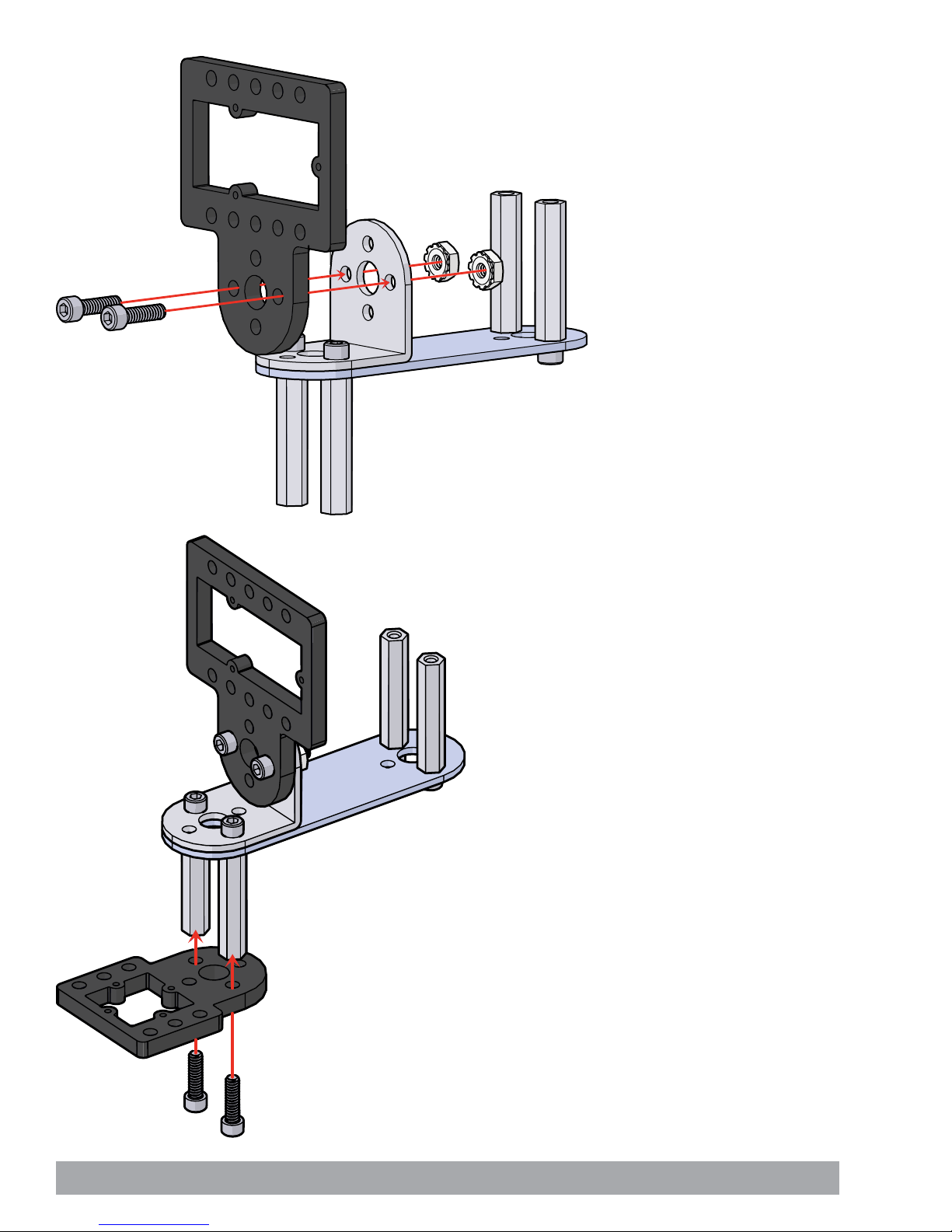
Step 1.2
Step 1.3
98 Building and Coding the PRIZM TaskBot
 Loading...