

Page 1

Page 2

Page 3

Table of Contents
Impulse Package Contents . . . . . . . . . . . . . . . . . . . . . . . . . . . . . . . . . . . . . . . . . . . . . . . . . . . . . . . . . . . . . . . 2
Introduction . . . . . . . . . . . . . . . . . . . . . . . . . . . . . . . . . . . . . . . . . . . . . . . . . . . . . . . . . . . . . . . . . . . . . . . . . . . 3
Planning Your Racetrack Setup . . . . . . . . . . . . . . . . . . . . . . . . . . . . . . . . . . . . . . . . . . . . . . . . . . . . . . . . . . . 3
Floor Setup . . . . . . . . . . . . . . . . . . . . . . . . . . . . . . . . . . . . . . . . . . . . . . . . . . . . . . . . . . . . . . . . . . . . . . . . . . . . 4
Gate Assembly . . . . . . . . . . . . . . . . . . . . . . . . . . . . . . . . . . . . . . . . . . . . . . . . . . . . . . . . . . . . . . . . . . . . . . . . . 4
Finish Gate Setup . . . . . . . . . . . . . . . . . . . . . . . . . . . . . . . . . . . . . . . . . . . . . . . . . . . . . . . . . . . . . . . . . . . . . . . 5
Other Track? . . . . . . . . . . . . . . . . . . . . . . . . . . . . . . . . . . . . . . . . . . . . . . . . . . . . . . . . . . . . . . . . . . . . . . . .
Start Gate Setup . . . . . . . . . . . . . . . . . . . . . . . . . . . . . . . . . . . . . . . . . . . . . . . . . . . . . . . . . . . . . . . . . . . . . . . . 6
Prelaunch Setup . . . . . . . . . . . . . . . . . . . . . . . . . . . . . . . . . . . . . . . . . . . . . . . . . . . . . . . . . . . . . . . . . . . . . . . . 7
Software Installation and Use . . . . . . . . . . . . . . . . . . . . . . . . . . . . . . . . . . . . . . . . . . . . . . . . . . . . . . . . . . . . 8
Manual Launching . . . . . . . . . . . . . . . . . . . . . . . . . . . . . . . . . . . . . . . . . . . . . . . . . . . . . . . . . . . . . . . . . . . . . . 9
Auto Launching . . . . . . . . . . . . . . . . . . . . . . . . . . . . . . . . . . . . . . . . . . . . . . . . . . . . . . . . . . . . . . . . . . . . . . . 10
Launch Practice . . . . . . . . . . . . . . . . . . . . . . . . . . . . . . . . . . . . . . . . . . . . . . . . . . . . . . . . . . . . . . . . . . . . . . . 11
After the Launch . . . . . . . . . . . . . . . . . . . . . . . . . . . . . . . . . . . . . . . . . . . . . . . . . . . . . . . . . . . . . . . . . . . . . . 11
Running a Race. . . . . . . . . . . . . . . . . . . . . . . . . . . . . . . . . . . . . . . . . . . . . . . . . . . . . . . . . . . . . . . . . . . . . . . . 12
Let’s Communicate! . . . . . . . . . . . . . . . . . . . . . . . . . . . . . . . . . . . . . . . . . . . . . . . . . . . . . . . . . . . . . . . . . . . . 12
Racetrack Safety . . . . . . . . . . . . . . . . . . . . . . . . . . . . . . . . . . . . . . . . . . . . . . . . . . . . . . . . . . . . . . . . . . . . . . . 13
5
Warranty
Pitsco provides a one-year limited warranty against defects in manufacturing on all items purchased. In a warranty
situation, Pitsco will arrange for the return of defective items for evaluation. Qualified Pitsco staff will determine
warranty coverage and notify the customer. Items under warranty will be repaired or replaced at Pitsco’s discretion.
Customers will be billed for all costs associated with non-warranty items.
59324 V0605
Page 4
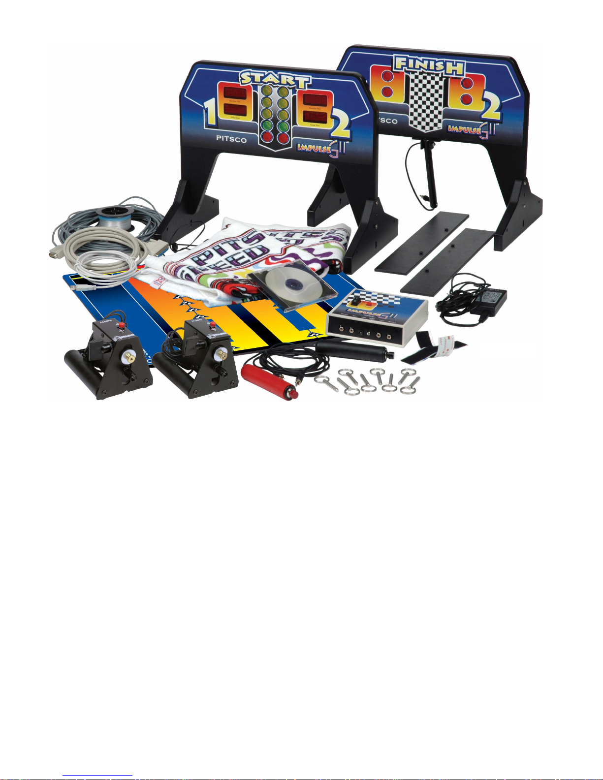
Impulse Package Contents
Figure 1
Start gate 2 deceleration towels
Finish gate 2 finish detector pigtails
4 gate supports 8 support mounting screws
8 steel pull pins 70-foot DIN cable
Spool of monofilament line Control box
2 launch pods 2 six-inch strips of Velcro® material
Power supply (12V, 2.5A) 2 black ABS line anchors*
2 launch triggers (1 red and 1 black) Start mat*
USB cable GII Race Management CD-ROM (Windows)
Please find the above items in the Impulse GII package. Make sure all components are present and
undamaged. Report any missing or damaged items to Pitsco Customer Service at 800-358-4983.
Note: Colors of some hardware items may vary.
Required Equipment and Materials (not included)
#2 Phillips screwdriver
Duct tape*
*floor use only
Got questions? We’ve got answers! 2 Call 800-358-4983
Page 5

Introduction
Congratulations on your purchase of the Impulse GII Racing System, an innovative tool for racing
student-designed dragsters. The Impulse GII’s quality construction ensures it will be a dynamic part
of a fun activity.
Pitsco has been providing teachers and students with exciting science and technology products for
years. As we forge ahead in education, we continue to develop and offer innovative products that
help students want to learn. Be sure to check the latest Pitsco Ideas & Solutions catalog for other
equipment, kits, books, videos, and activities.
Since its inception, Pitsco’s mission has been to provide teachers with motivating, teacher-friendly
education tools. We are confident this product will aid in achieving this goal. However, we realize
that change is constant and necessary to meet the needs of teachers. To that end, we encourage your
written response and input about the Impulse GII or any Pitsco product.
Planning Your Racetrack Setup
Determine a good location for the track setup and take measurements to ensure there is enough
space. The track can be almost any length between 30 feet and 80 feet. (If your track is less than 40
feet, you should use “short shot” four-gram CO2 cartridges. See the Pitsco catalog.)
Here are some things to think about when planning the racetrack setup:
Actual Racing Distance
Actual racing distance extends from the start line to the finish line. The ideal racing distance is 20
meters (65 feet, 6 inches) because it is approximately 1/20 of a quarter mile. This is useful for making mathematical comparisons to real dragsters. (Metric dragsters are also roughly 1/20 the size of
real dragsters.)
Staging Zone
Allow a minimum of four to five feet at the start end for staging cars. A five-foot staging will allow
four pairs of cars to be staged behind the launchers. If available, more space can be used to stage
more cars.
Deceleration Zone
Allow a minimum of four feet past the finish end of the track to stop the cars. A deceleration towel
will be placed in each lane approximately two feet behind the finish line to absorb the impact of the
speeding cars and bring them to a safe halt.
Parking Zone
Allow for a parking zone behind the deceleration zone. The parking zone should be the same length
as the staging zone so it will accommodate the same number of cars. There should be adequate
space to park all of the cars loaded onto the start end of the track without encroaching into the
deceleration area.
3 59324 V0605
Page 6
Floor Setup
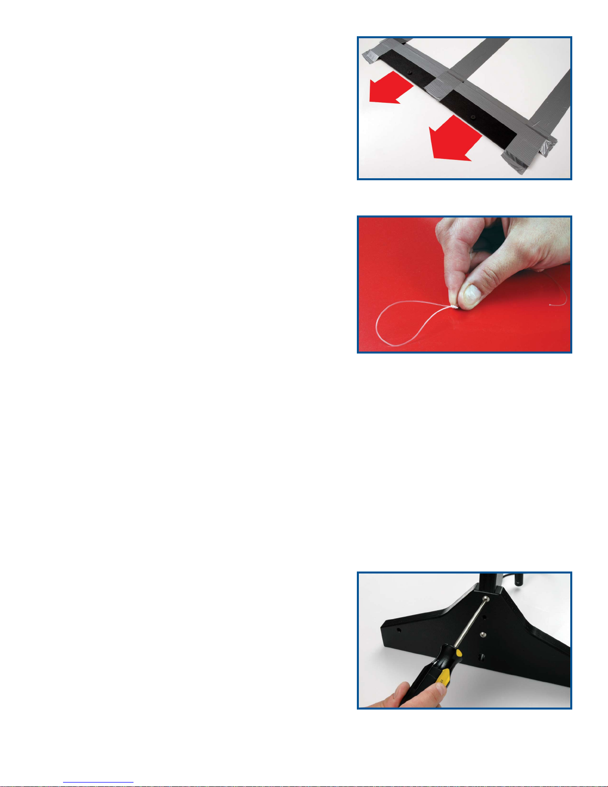
1. At the start and finish ends of the track location, fasten
the black ABS line anchors to the floor with duct tape
(Figure 2).
2. Locate the spool of monofilament line. Tie a loop in the
end of the line – use a knot such as the overhand or
figure eight (Figure 3).
3. Hook the loop over one of the anchor screws on the
ABS line anchor.
4. Walk to the opposite end of the track, allowing the line
to unreel from the spool as you go. Extend the line just
past the anchor and cut it.
5. Tie a loop at this end of the line using the overhand or
figure eight knot so the loop is approximately 24 inches
short of reaching the anchor screw. For example, if the
track is 80 feet long, tie a loop in the line so the length
of the line plus the loop is 78 feet long. The line should
be tightly stretched. A tight line should prevent cars
from going off course as they race down the track. Cut
off any excess line extending from the loop’s knot.
Note: If your track is shorter than 80 feet, 24 inches short
of the anchor screw might make the line overly tight.
6. Repeat Steps 2-5 for the other lane.
7. Attach the strips of Velcro material to the black rectangles on the start mat.
Figure 2
Figure 3
8. Place the start mat in position, sliding it under the two monofilament lines. Align the arrows on
the mat with the two monofilament lines.
FasTrak Elevated Racetrack Setup
Follow the procedures outlined in the FasTrak User’s
Guide for setting up the track and stretching the monofilament line.
Gate Assembly
The start and finish gates will come unassembled. To
assemble them, simply attach the legs of each gate with
the four screws, screwing two in each side of the gate
(Figure 4). Now the gates are ready to be used. Caution:
Do not overtighten the screws.
Got questions? We’ve got answers! 4 Call 800-358-4983
Figure 4
Page 7
Finish Gate Setup
1. Place the finish gate over both lanes at the finish end of
the track. For the elevated track, insert four of the pull
pins into the holes on both sides of each finish gate leg.
Place the gate on the track so the pins rest on top of the
track sides.
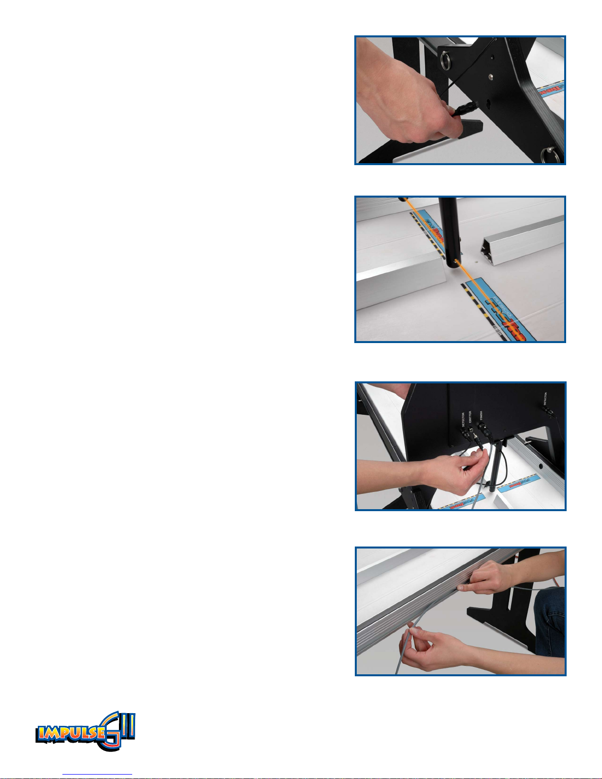
2. Insert the finish detector pigtails into the hole, or
socket, that is on both legs of the finish gate (Figure 5).
Note the positions of the emitter bulbs on either side
of the emitter tube, which is the tube that hangs down
from the center of the finish gate. The detectors should
be aligned with the emitter bulbs (Figure 6).
Insert the detector for Lane 1 in the upper socket and
insert the Lane 2 detector in the lower socket, corresponding to the position of the emitter bulbs.
3. Plug the end of each detector pigtail into the jacks
labeled “Detector” on the back of the finish gate. When
facing the back of the finish gate, the Lane 1 detector
goes in the right jack, and the Lane 2 detector goes in
the left jack.
4. Plug the cord extending from the emitter tube into the
jack labeled “Emitter” on the back of the finish gate
(Figure 7).
Figure 5
Figure 6
5. Insert the end of the 70-foot cable into the DIN socket
labeled “Finish” on the finish gate. Routing the cable
along the right side of the track, unroll the cable and
extend it to the start end.
FasTrak Only:
6. Down the length of the track, run the DIN cable in the
conduit that is on the side of the FasTrak. Run the
cable down to the start gate and control box area
(Figure 8).
Figure 7
Other Track?
If you have another track, such as the metal EL 80 track,
please call Customer Service at 800-358-4983 to learn how
to use the Impulse GII system with your track.
5 59324 V0605
Figure 8
Page 8
Start Gate Setup
Note: You will need a small table or stable surface on which to
place the control box. This surface should be very close to the
track.
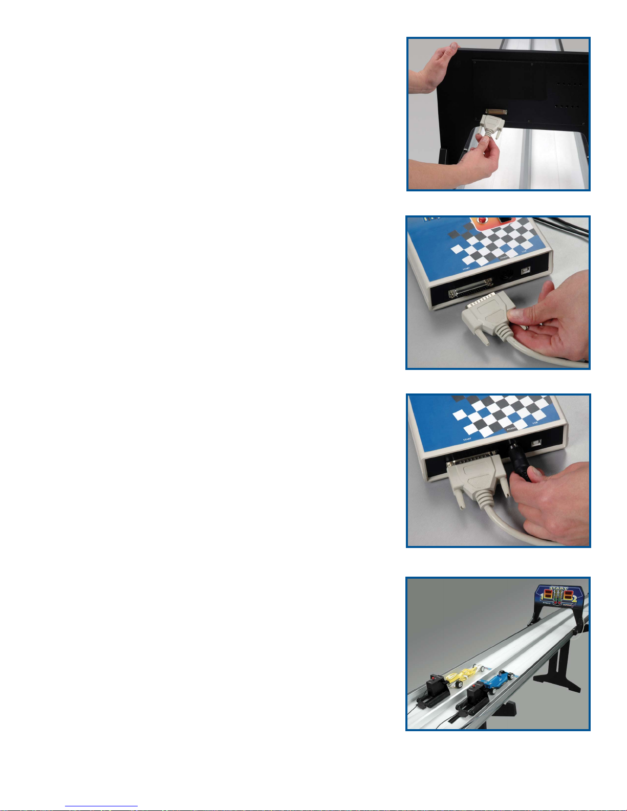
1. Plug the 25-pin, 10-foot cable into the port on the back of the
start gate (Figure 9).
2. Insert the other end of the 25-pin cable into the control box
where it is labeled “Start” (Figure 10).
3. Connect the end of the 70-foot cable to the Finish socket on
the control box (Figure 11). If you have set up a short track,
you may want to tie up the excess cable to avoid a tripping
hazard.
4. Plug the launch pod cords into the control box ports labeled
“Pod 1” and “Pod 2.” Set the launch pods in their respective
lanes behind the start line. When facing the front of the start
gate, the left side is Lane 1 and the right side is Lane 2
(Figure 12).
Figure 9
5. Connect the cord from one launch trigger to the control box
port labeled “Trigger 2.” Connect the other trigger cord to the
port labeled “Trigger 1.”
Note: One trigger is black and the
other is red, but it doesn’t matter which trigger is connected to
which port. The colors are just to help you keep track of which
lane each trigger is for.
6. Insert the 12-volt power supply cord into the jack labeled
“Power” on the front of the control box. Plug the power sup
ply into a standard AC outlet.
7. If connecting the Impulse GII system to a computer, do so
now by plugging the USB port from the computer into the
jack labeled “USB” on the control box.
Figure 10
-
Figure 11
Got questions? We’ve got answers! 6 Call 800-358-4983
Figure 12
Page 9
Prelaunch Setup
1. Locate the two deceleration towels. Fold the towels in half lengthwise one time, width-wise one
time, and lengthwise again. Place one towel in each lane on the finish end of the track approximately two feet behind the finish line. Make sure the end of the towels with the most edges
showing is facing the finish gate. Careful placement of the towels is critical to bring the cars to a
safe halt at the end of each run.
2. Make sure both launch pods are in the uncocked position before powering up the system.
(Switching on the power when the launch pods are cocked could prematurely launch the cars.)
To put the pods in the uncocked position, make sure the switch on the side of each pod is flipped
in the horizontal position.
3. Switch on the Impulse GII system by turning on the power switch on top of the control box. The
displays on the start gate should light.
If the red lights are lit on the Finish gate, then the
detectors are not aligned correctly. Move the emitter
tube forward or back until it is adjusted so the red
lights turn off.
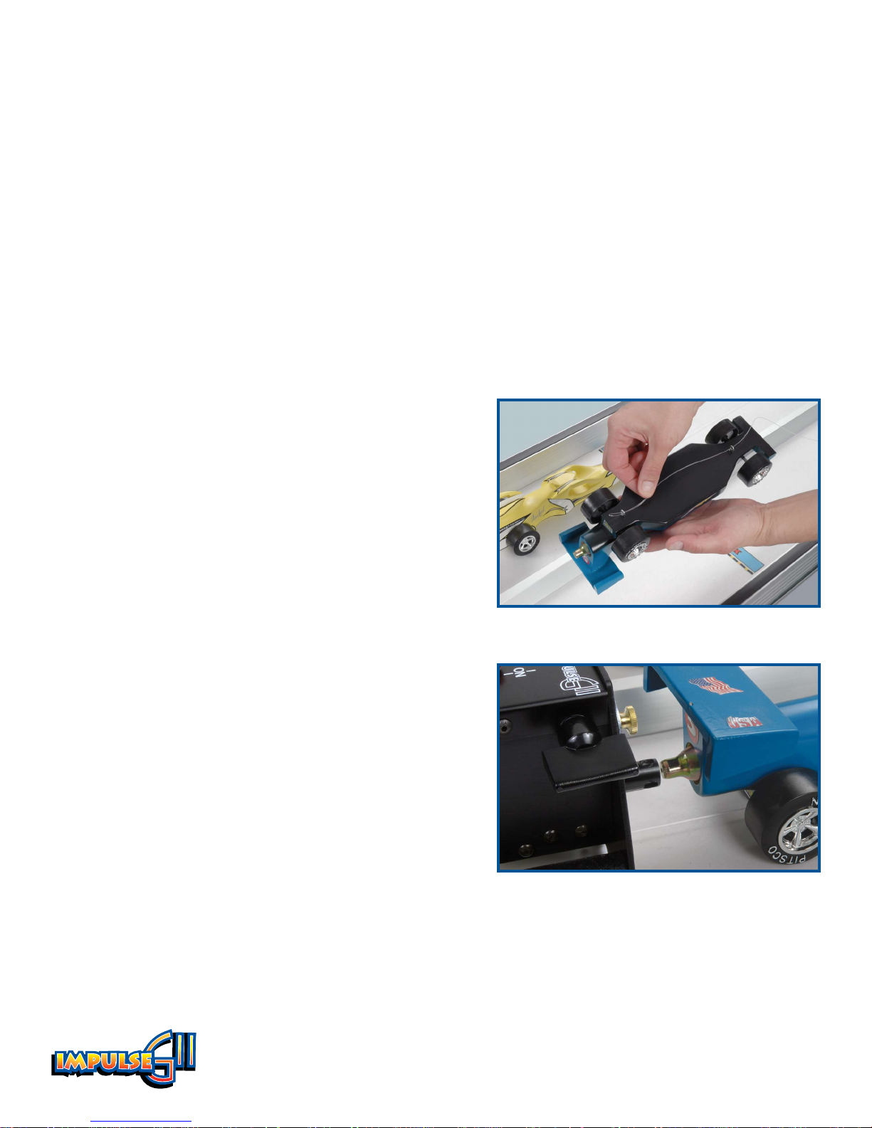
4. Detach the Lane 1 monofilament line from the start
end anchor. Thread the line through the screw eyes
of the car – thread the front screw eye first, then the
rear screw eye (Figure 13). Reconnect the line to the
anchor. Repeat for Lane 2.
Note: if you wish to stage
several other cars behind the launch pods, you can
do so before reconnecting the line to the anchor.
Figure 13
5. Position the cars at the start line. The front of the cars
should be aligned with the line.
6. Insert a Pitsco CO
cartridge in each dragster. Make
2
sure the cartridge is fully seated in the car’s cartridge
hole.
7. Position the launch pods at the rear of the cars so the
firing sleeve engages the neck of the CO2 cartridges
(Figure 14). This may require a height adjustment to
the launch pods using the thumb screws on the front
of each pod. The launch pods should be secured in
place by the Velcro material.
7 59324 V0605
Figure 14
Page 10
8. Make sure the finish end is prepared for the
launch with towels in place to stop the cars.
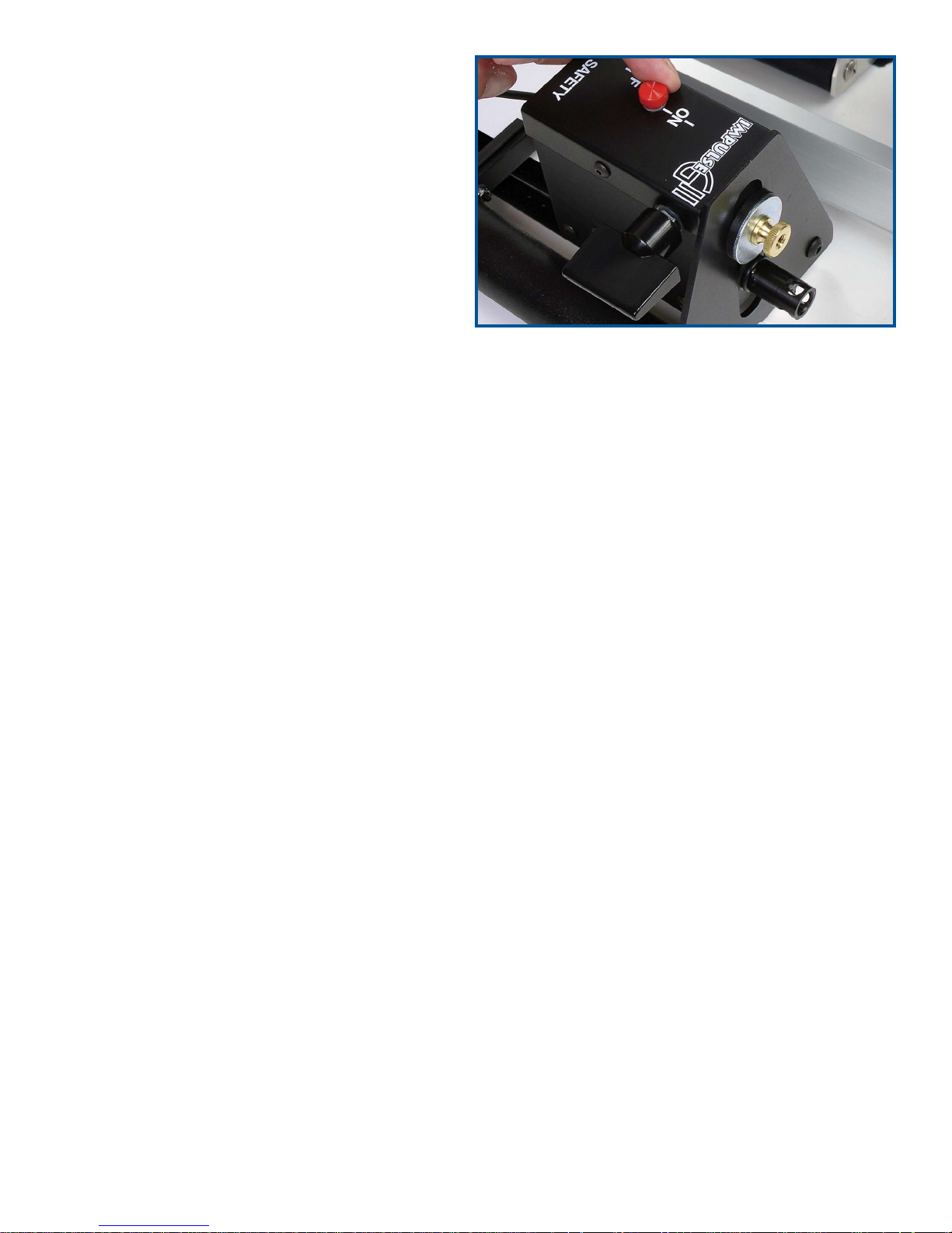
9. Cock the launch pods using the switch on
the side of each pod – the switches will be in
the vertical position when cocked. Move the
safety lever to the On position (Figure 15).
This will prevent accidental launches.
10. Back each car into its pod, making sure each
car’s cartridge is engaged in the firing sleeve.
The cars are now ready to launch.
To uncock the launchers, move the cars away
from the launch pods. Unlock the safety
levers. Firmly grasp the cocking levers and
slide them over to the Off position.
Software Installation and Use
Figure 15
Note: The Race Management software is only compatible with the Windows XP operating system.
1. Insert the
Race Management CD-ROM into your CD drive. The installer should autorun; follow
the instructions in the window.
2. To use the software, launch
Race Management. To learn more about using the software, see the
online help under the Help menu.
Got questions? We’ve got answers! 8 Call 800-358-4983
Page 11
Manual Launching
This mode allows competitors to individually fire their own
cars. The competitors’ reaction times – or the start times –
are a factor in the race.
Caution: Do not unplug any of the race system components
while using the system.
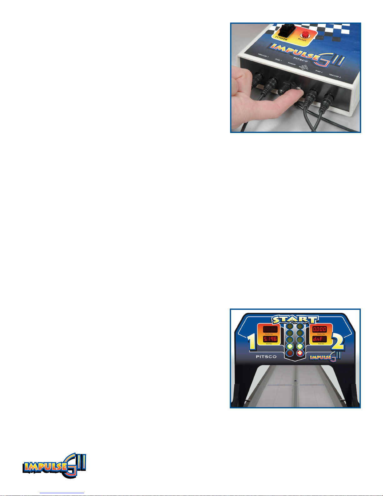
1. Set the mode lever on the front of the control box to
Manual (Figure 16).
2. Make sure everyone is clear of the track.
3. Ready the competitors – each should have his or her
respective trigger and be attentive to the “Christmas tree” display on the start gate.
4. Move the launch pod safety levers to the Off position.
5. When ready, press the Reset button on the control box.
The Christmas tree lights will activate. The three top pairs of yellow bulbs will light in succes
sion, followed by the pair of green lights. Competitors should activate their launch triggers when
the green bulbs light.
Figure 16
-
And They’re Off!
After the cars cross the finish line, the finish gate will indicate the winning lane with alternating red
lights.
The start gate will display the race times and reaction times. The winning times will flash.
In Case of a Red Light
If a competitors activates the launch trigger too early
(before the green lamps light), his or her car will not launch.
Then, the bottom red lamp for that lane will illuminate
(Figure 17). This is known as a “red light” start.
9 59324 V0605
Figure 17
Page 12
Auto Launching
This mode fires both cars simultaneously.
Caution: Do not unplug any of the race system components while using the system.
1. Set the mode lever on the control box to Auto.
2. Make sure everyone is clear of the track.
3. Move the launch pod safety levers to the Off position.
4. To start the launch, press the Reset button on the control box.
The “Christmas tree” lights on the start gate will begin their sequence. When the green pair of
bulbs light, the cars will be launched.
And the Winner Is . . .
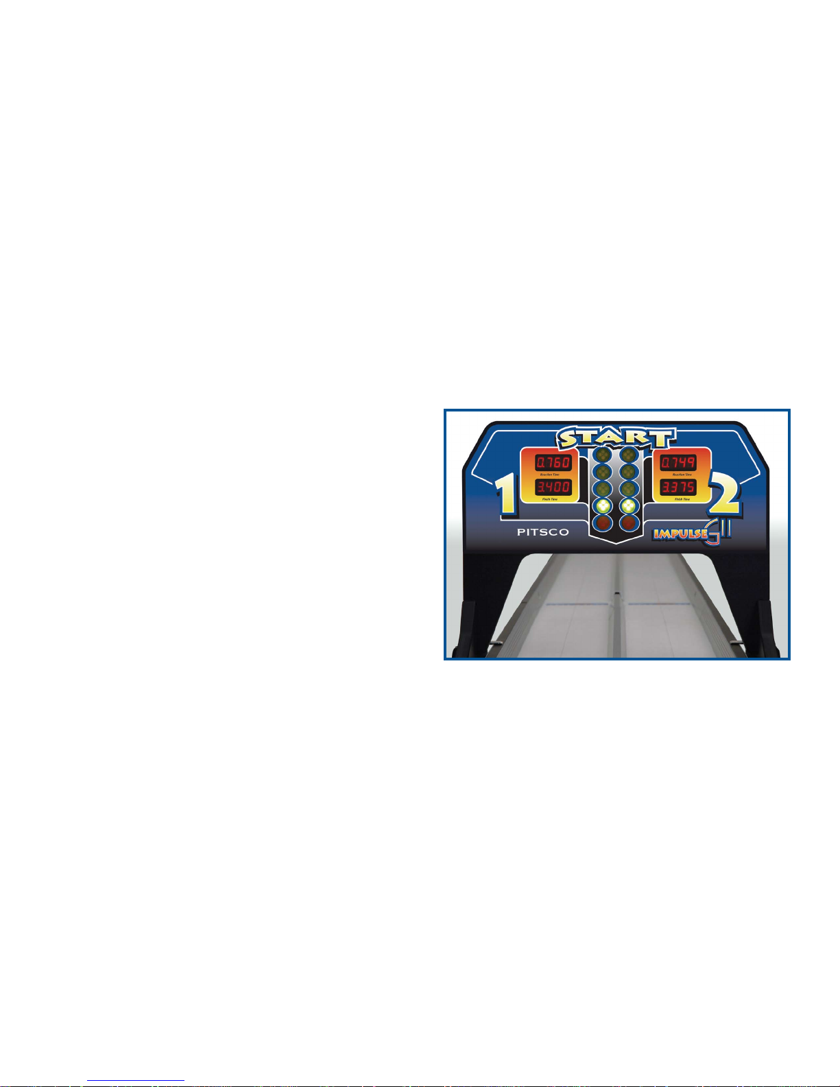
The finish gate indicates the winning lane with a
pair of blinking red lights.
The start gate displays both race times in the
windows labeled “Finish Time.” The winning time
will flash (Figure 18).
Figure 18
Impulse Racing System 10 59324 V0605
Page 13
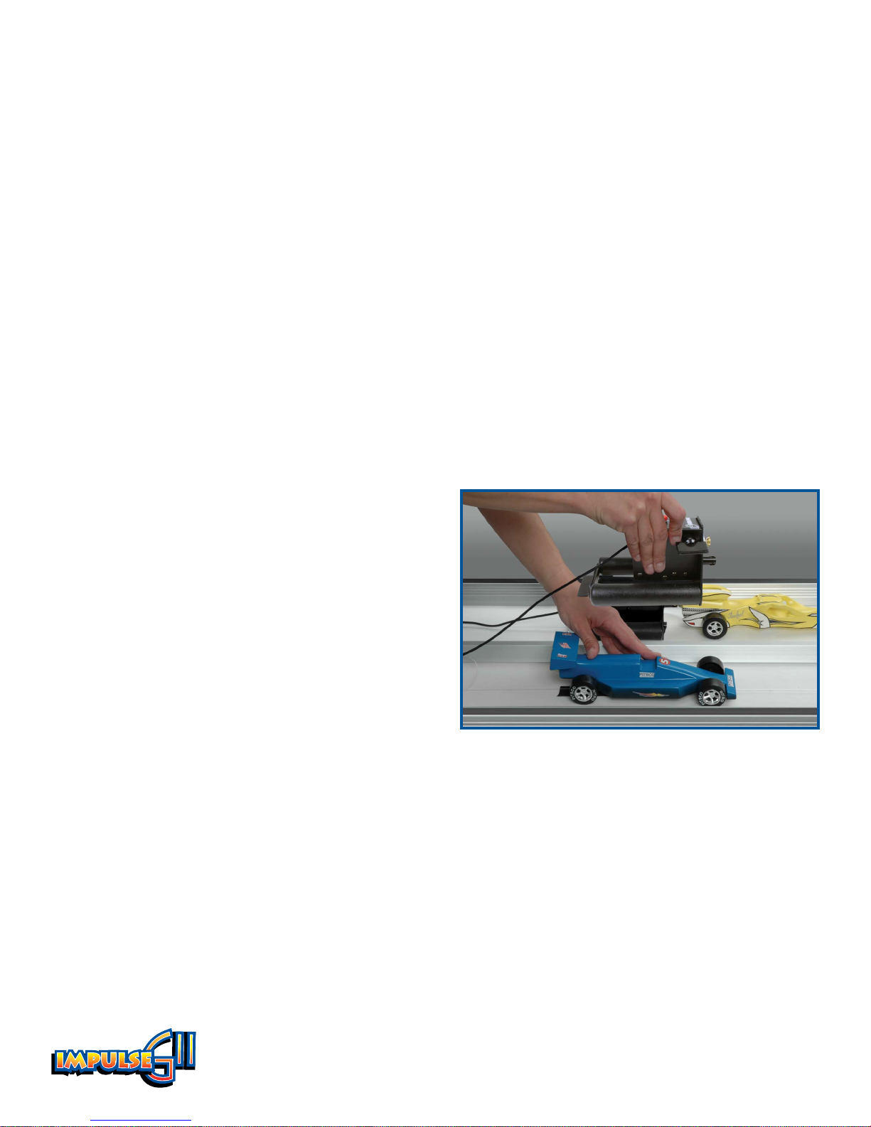
Launch Practice
The Impulse GII can be used to hone launching skills without actually firing cars off the line. This is
a useful activity for perfecting the launch technique and reducing reaction time.
To conduct a launch practice, skip the entire prelaunch setup process. Proceed with the manual
launch as described in Steps 1-4 on page 9. The start gate will display reaction times for both lanes.
The finish time windows will continue counting until the Reset button is pressed. Both launch trig
gers must be activated before the system will reset.
-
After the Launch
As the cars reach the end of the track, they should strike the towels and come to a safe halt.
Finish End
1. Move the towels aside and roll the cars to the end of the parking area.
2. Replace the towels in their position just behind the finish gate.
Start End
3. Lift the launch pods and roll the next pair of
staged cars to the starting line (Figure 19).
4. Follow Steps 5-7 of the prelaunch setup
procedure on page 7 to prepare the next pair of
cars.
IMPORTANT: To prevent possible injury from an
accidental launch, do not cock the launch pods until
the finish crew has signaled they are ready (having
completed Steps 1 and 2).
5. When the prelaunch setup is complete, press the
Reset button to start the next launch sequence.
Figure 19
11 59324 V0605
Page 14

Running a Race
This section will help you run a race efficiently and safely. You should select several responsible
individuals to help run the race. Each race team member should be assigned a task and should have
a clear understanding of their responsibilities. Also, review the racetrack safety rules on page 13
with the team members. The last thing you want on race day is for an injury to spoil the fun.
Running a race takes teamwork. As few as two people can run a race, but a team of four or more can
run it more efficiently. A race team consists of two crews.
A start crew must do the following tasks:
• Thread the cars onto the monofilament line, staging several pairs of cars to be on deck.
• Position the cars at the start line and conduct the prelaunch setup.
• Launch the cars (in auto mode).
• Roll the next pair of cars into position to prepare for the next launch.
• Reload the staging area with another heat of cars.
A finish crew must do the following tasks:
• Position the checkered towels at the finish line to safely stop the cars.
• Park the cars after the run and replace the towels.
• Signal the start crew when ready to proceed with the next run.
• Unload the track after the staged cars for that heat have completed their runs. This entails detach
ing the monofilament lines from the finish end anchor and removing the cars.
-
In addition, it may be necessary to appoint a race official who records times and keeps track of elimination brackets.
Let’s Communicate!
Effective communication between crews is essential when conducting a race. The finish crew should
signal the start crew when they are ready to proceed with the next run. The start crew should NOT
cock the launch pods until they have received the ready signal from the finish crew. The start crew
should also make sure everyone is clear of the track before starting the launch sequence.
These steps are necessary to prevent injury during a race. They also help to prevent damage to cars.
Running a race is simple and fun, but the race team members should be attentive, keep safety
foremost in their minds, and communicate with each other clearly.
Got questions? We’ve got answers! 12 Call 800-358-4983
Page 15
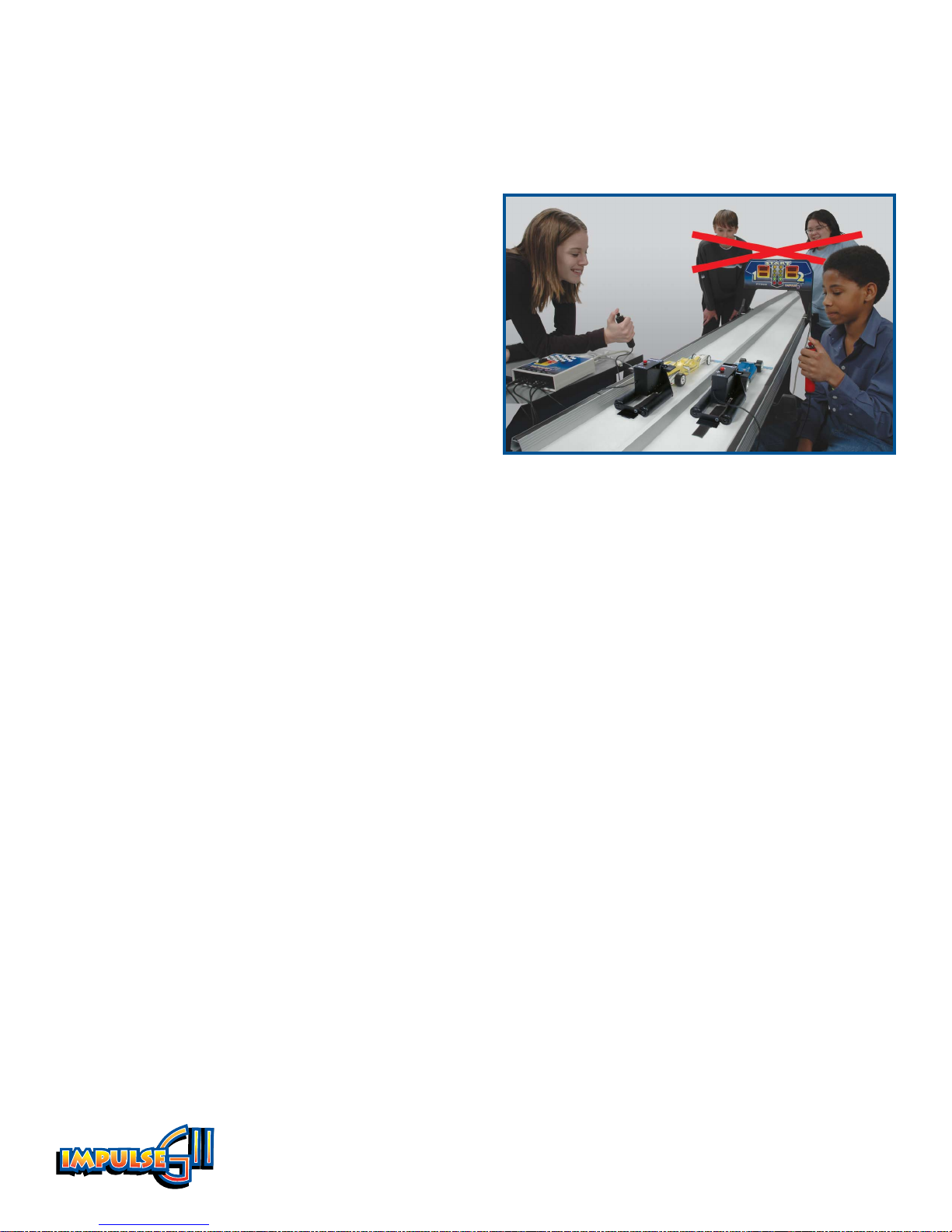
Racetrack Safety
The Impulse GII system, with its low-voltage electronics and launcher safety levers, is an extremely
safe racing system. Still, the following safety rules should be read and strictly followed to prevent
injury and car damage.
1. Before cocking the launch pods, make sure
everyone is clear of the track. Also, make sure the
towels are in place to stop the cars at the end of
the track.
2. Move the launch pod safety levers to the On
position after cocking the launch pods.
3. Never turn the control box power switch on or
connect the power supply when the launchers are
already cocked. This could trigger the launchers.
The launchers should never be cocked when the
power is off or disconnected from the unit. If the
power is shut off or interrupted (due to a power
Figure 20
Never lean over the track. Though rare, cars can come
loose from the monofilament line and leave the track.
outage, for example) during a race, immediately
check the launch pods and uncock if necessary.
4. The Impulse GII system should be used only with the supervision and guidance of an instructor.
13 59324 V0605
Page 16
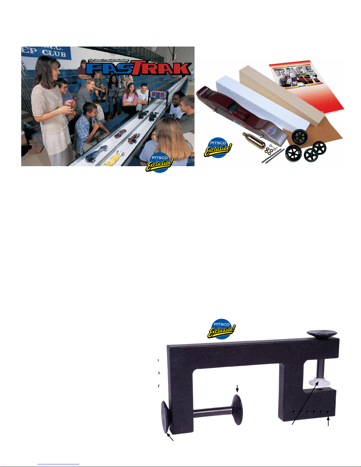
More great dragster products – check them out!
Call 800-835-0686 for pricing or visit us online at www.pitsco.com.
PITSCO FASTRAK ELEVATED RACETRACK
Pitsco’s smooth-surfaced, elevated racetrack provides a great alternative
to racing metric dragsters on the floor. The FasTrak simplifies the process
of conducting races and improves viewing for spectators. Check out these
outstanding features:
• Self-aligning, tab-and-slot system guarantees flush joints between each
track section.
• Custom-extruded, anodized aluminum rails provide strength and
stability.
• High-impact plastic track surface is strong, durable, and scratch
resistant.
• Shorter (eight-foot) track panels with fold-down leg supports are easy to
assemble and to store.
• Precision-made track supports ensure even height and level sit.
The FasTrak is designed to simulate a scaled-down quarter-mile
racetrack. Because metric dragsters are about one-twentieth the size of
real dragsters, the FasTrak’s racing distance, from start to the finish line, is
20 meters, one-twentieth of a quarter mile. This simplifies mathematical
comparisons to real race cars.
A staging area behind the start gate is big enough for four to five cars
to be positioned in each lane. Adequate deceleration distance is provided
at the end of the track for cars crossing the finish line. The FasTrak package
includes 10 eight-foot track sections and 11 track supports.
22049 FasTrak Elevated Racetrack
PITSCO DRAGPAK (for 50 students)
Now you can get the classic dragster in a convenient
Power Pak for the whole class! This hands-on activity has
been the best motivational project in technology education
for more than 20 years. Everything you need to design
and build 50 metric dragsters is in the DragPak. Optional
expanded polystyrene foam blanks allow students to
experiment with body shape before cutting.
13244 Basswood
13243 Basswood without expanded polystyrene blank
13245 Balsa Wood
13246 Balsa Wood without expanded polystyrene blank
PITSCO METRIC KIT MK-200 (BASSWOOD)
Design a shorter, lighter dragster with this kit instead
of our regular Metric Dragster Kit. The only difference is that
this wooden body blank is about 100 mm shorter than the
one in the Metric Dragster Kit.
13216 Kit with expanded polystyrene blank
13223 Kit without expanded polystyrene blank
PITSCO WHEEL DEAL
The Pitsco Wheel Deal is the ideal tool for CO2 dragster
wheel assembly. The Wheel Deal is a hand tool designed with
two comfortable presses, one for hub insertion into a wheel,
the other for final assembly of the wheels, washers, and axles
on the dragster. We've even included axle height locators as
an added feature. No more stubborn hubs, broken wheels, or
difficult axles – the Pitsco Wheel Deal is here!
The Wheel Deal is a unique four-in-one tool that
simplifies the following tasks of dragster building:
• Marking axle height accurately
• Assembling wheels and hubs
• Inserting axles into wheels
• Mounting wheels on car (reducing car damage)
25500 Wheel Deal
Axle press head
Wheel and axle press
Hub press
Axle height
holes
 Loading...