

Page 1

PITE 3830 Ground-Fault Locator
User Manual
P-100929-V1.3
4/F, Bldg A, Chiwan Industrial Park, Shaodi Rd.,
Chiwan, Shekou Area, Shenzhen, China
TEL: +86-755-2680 5759
FAX: +86-755-2688 0310
www.pitetech.com
Page 2
PITE 3830 Ground-fault Locator User Manual
2
▲Safety Information
For your protection, please read this safety information completely before operating the locator.
Carefully observe all warnings, precautions and instructions.
WARNING: Servicing described in this manual is to be done only by qualified personnel. To avoid
electrical shock or equipment damage, do not service the instrument unless you are qualified and with
PITE’s instruction.
DANGER
Safety testing has been done on this instrument thoroughly
before shipment. However, mishandling during use could
result in injury or other bad consequences, as well as damage
to the instrument. Make sure that you understand the
instructions and precautions in the manual before use. We
disclaim any responsibility for accidents or injuries not resulted
directly from instrument defects.
Safety Symbols
Description of symbols used in this manual.
WARNING
Indicates correct operation to prevent a significant hazard that
could result in serious injury or other bad consequences to
users or instrument.
NOTE
Indicates advisory items related to performance or correct
operation of the instrument.
▲Operating Precautions
To avoid electrical shock or fire, read these precautions first before using the locator:
♦ Except as explained in this manual, do not attempt to service this equipment yourself.
♦ Do not operate the locator around explosive gas or vapor.
♦ Use only PITE’s testing leads and other accessories with the locator.
♦ Before use, inspect the locator, testing leads and other accessories for mechanical damage and
replace when necessary. Pay special attention to the insulation surrounding the connectors.
♦ Remove all clamps, testing leads and accessories that are not in use.
♦ Do not apply the instrument in other purpose not described in this user manual
♦ Ensure the equipment is provided with adequate ventilation.
♦ Proper installation is essential to the correct functioning of your analyzing software CD. If you have
any questions about installation, please contact your supplier for assistance.
♦ This manual describes the general installation and use of the testing system. If your system has
features or accessories not addressed in this manual, please contact your supplier.
Page 3

PITE 3830 Ground-fault Locator User Manual
3
Catalogue
1. ABOUT PITE 3830 ...............................................................................................................................4
1.1 Main Unit & Signal Receiver........................................................................................................4
1.2 Accessories .................................................................................................................................4
1.3 Function ......................................................................................................................................5
1.4 Feature........................................................................................................................................6
1.5 Application...................................................................................................................................6
1.6 Technical Parameter....................................................................................................................6
1.7 Abbreviation definition .................................................................................................................7
2. WIRE CONNECTION...........................................................................................................................7
2.1 Preparation..................................................................................................................................7
2.2 Main Unit connection...................................................................................................................7
2.2.1 Connection for Insulation Test ...........................................................................................8
2.2.2 Connection for Grounding Location...................................................................................8
2.2.3 Other Connection ..............................................................................................................8
2.3 Get Started..................................................................................................................................8
3. MAIN OPERATION...............................................................................................................................9
3.1 Power On ....................................................................................................................................9
3.2 Insulation Measurement ..............................................................................................................9
3.2.1 Voltage Testing..................................................................................................................9
3.2.2 Insulation Measurement..................................................................................................10
3.3 Ground-Fault Location...............................................................................................................11
3.4 Data Management.....................................................................................................................13
3.4.1 Data Query......................................................................................................................13
3.4.2 Delete Data .....................................................................................................................14
3.4.3 Transfer to USB Drive .....................................................................................................14
3.5 System Management ................................................................................................................15
3.5.1 Time Setting ....................................................................................................................15
3.5.2 Calibration .......................................................................................................................15
3.5.3 System Update................................................................................................................15
4. ANALYZING SOFTWARE ..................................................................................................................16
4.1 Software Installation ..................................................................................................................16
4.2 Software Operation ...................................................................................................................18
4.2.1 File Processing................................................................................................................20
4.2.2 Data Analysis ..................................................................................................................22
4.2.3 Administrator ...................................................................................................................24
4.2.4 About...............................................................................................................................27
5. SERVICE & MAINTENANCE .............................................................................................................27
5.1 Cleaning ....................................................................................................................................27
5.2 Storage......................................................................................................................................28
6. FAQ....................................................................................................................................................28
7. ORDER INFORMATION.....................................................................................................................28
Page 4
PITE 3830 Ground-fault Locator User Manual
4
1. ABOUT PITE 3830
1.1 Main Unit & Signal Receiver
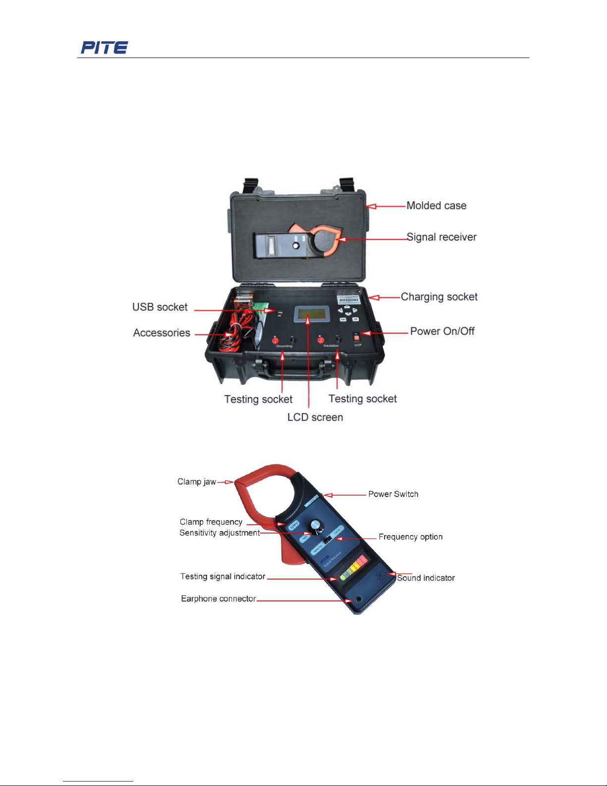
Main unit contains: carrying case, LCD screen, 6 buttons, 1 USB socket, 2 sockets for insulation test, 2
sockets for grounding test, 1 socket for main unit charging and 1 main unit power switch.
Sample picture of Main Unit is as below:
Fig. 1.1.1
Sample picture of Signal Receiver is as below:
Fig. 1.1.2
325Hz signal receiver has frequency options for Selected Hz and Full Hz. They are applied in different
environments.
Selected Hz means only one frequency (325Hz) is used during ground fault location. Full Hz indicates
that the signal receiver may use different frequencies available to pinpoint ground fault. In this case,
signal will be comparatively stronger than that of selected Hz. However it (Full Hz) may be interfered by
surrounding circumstances if there are other equipments running with different frequencies. In these
Page 5
PITE 3830 Ground-fault Locator User Manual
5
complicated circumstances, Full Hz may not be as accurate as Selected Hz.
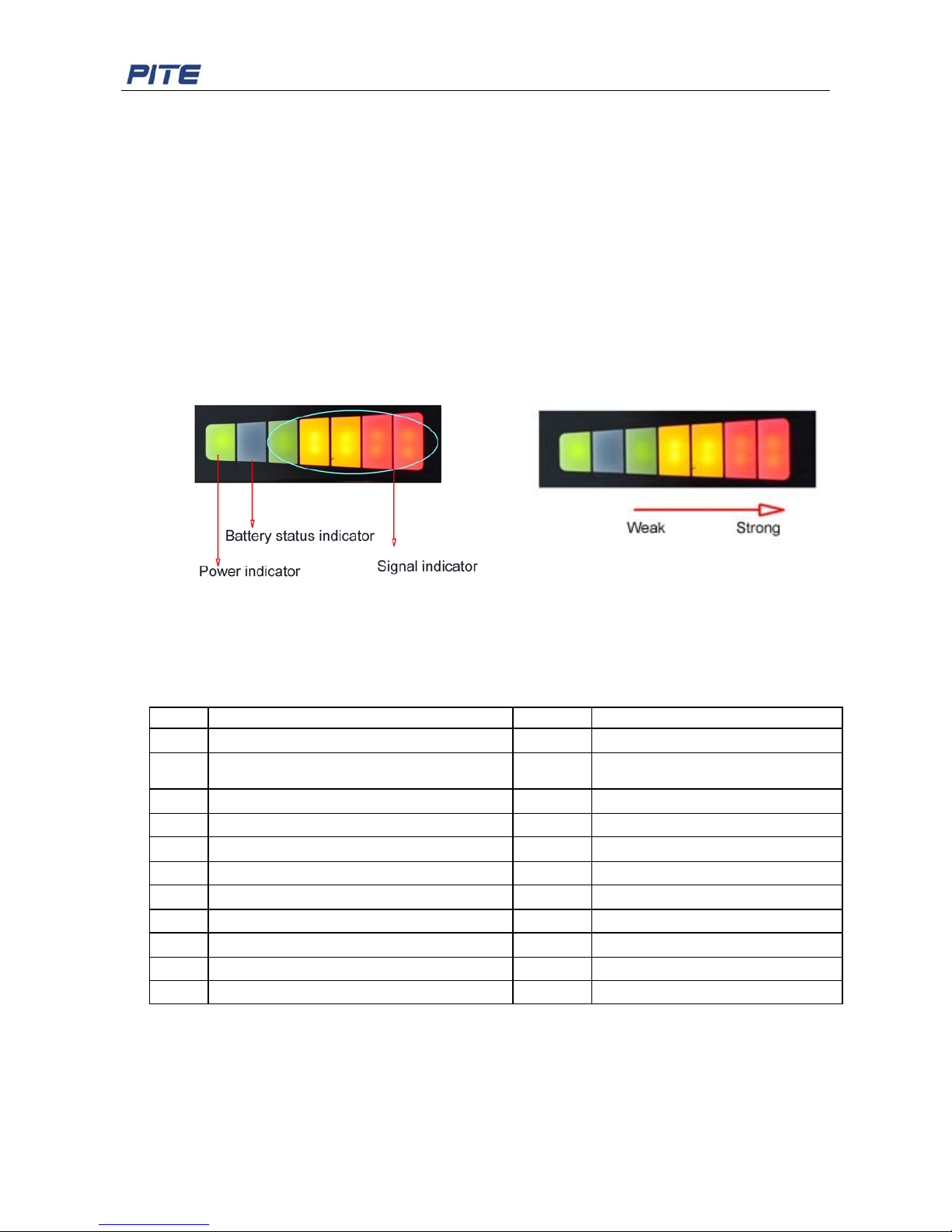
Details about testing signal indicator
Fig. 1.1.3 shows the meaning of signal indicator. This is one way to check the ground fault. We will
introduce in 3.3 Ground-Fault Location in details.
As the signal receiver is switched on, the power indicator (in green) is on.
When battery is full charged, the second grid is dim. As the battery is low, the light will be on (in green).
You are suggested to charge it timely to ensure its performance.
When signal is detected in the circuit, signal indicators will be on in the consequence of green, orange
and red from the 3
rd
grid to the 7th. Signal light of the 4th grid is strong than the 3rd, and so forth like Fig
1.1.4.
NOTE: Due to signal interference at the beginning, the receiver may be in full signal right after it is
switched on. Wait for a few seconds, the signal will be normal.
Fig. 1.1.3 Fig. 1.1.4
1.2 Accessories
All the following accessories are contained in the carrying case. After receiving the unit from your
supplier, please make sure you have the following items:
1.3 Function
1) Ground fault location
It tests the insulation status of device in DC system. When busbar insulation has breakage in certain
point, its resistance will reduce to be lower than required. It may even cause power break-off which is
costly to repair. Fast location and elimination of insulation fault will be significant for electricians and
Item Description Number Note
1 PITE 3830 Main unit (with carrying case) 1
2 Signal receiver 1 Has two options: 325Hz and
2.5Hz
3 8.4V battery 1
4 Battery charger 1 For Signal receiver
5 Power adaptor 1 For PITE 3830 main unit
6 Earphone 1
7 2.5 M testing lead 2 1 red and 1 black
8 Testing alligator 2 1 red and 1 black
9 User manual 1 For testing and data analyzing
10 Software CD 1
11 USB drive 1
Page 6
PITE 3830 Ground-fault Locator User Manual
6
technicians.
By using PITE 3830 Ground-Fault Locator, you could fast pinpoint the breakage.
System composition: main unit of Ground –fault Locator and a signal receiver (clamp-shaped)
Basic theory:
In the breakage of busbar, there is loose of electricity to the ground and thus generate a faulty
“grounding”. When testing leads of PITE 3830 are connected to the ground and busbar, there will be a
return circuit (see Fig 2.2.2 in 2.2.2 Connection for Grounding Location).
Signal generator (main unit) will send a low-frequency voltage signal of 0.1Hz~1000Hz between the
testing target and grounding malfunctioned circuit. The breaking point will generate leaking current. As
the grounding receiver (signal receiver) moves in the circuit, different points in the circuit will have
different reaction in the indication of sound warning and light flashing. Based on the sound volume in
the signal receiver, it will pinpoint the grounding fault. For detailed operation, please refer to 3.3
Ground-Fault Location.
2) Insulation test
It tests and records voltage and insulation status for tested target.
3) Data management function
With the management software, you could check detailed wave, have good follow-up for insulation
status, find insulation defection in time and predict insulation life span of equipments.
1.4 Feature
♦ Insulation tester and ground fault locator, two function in one
♦ Test and record insulation status of facilities
♦ No disconnection of the electrical installation when ground fault location is operated
♦ Fast locations for ground fault even when cables are buried unearth
♦ Signal-generator with adjustable frequency and voltage, convenient for testing
♦ Reflects aging status of facilities for further reparation
♦ Powerful management software on PC for trouble analyzing
♦ Reduced maintenance and repair costs
1.5 Application
1). Communication: communication and any other electric equipments and circuits
2). Electric utility: insulation testing and malfunction pinpoint for DC system and negative rail
3). Others: electric equipments and circuit in aviation, metallurgy, auto and household appliance.
1.6 Technical Parameter
Measuring range
V: 0.00-1000V Insulation R: 20kΩ-500MΩ (250V)
50kΩ-1000MΩ (500V) 100 kΩ-2000MΩ (1000V)
Min resolution
Voltage: 0.1V Insulation R: 0.01 MΩ
Accuracy
Voltage: 1%rdg±8dgt
Insulation R: 0.5 MΩ-100 MΩ 5%rdg±6dgt
﹥100 MΩ: 10%rdg±6dgt
Output signal
voltage: 0-1000V±10% Frequency: 1-1000Hz
Power consumption
≥4 hours(continuous operation)
Memory
32k×8bit Non Volatile SRAM
Page 7
PITE 3830 Ground-fault Locator User Manual
7
Displaying screen
128×64 pixels LCD
Communication
USB interface Battery Li-ion
Dimension
340×250×140mm Weight 3.0KG
Humidity
80%R.H Temperature -5℃-40℃
Receiver
Testing accuracy
≤0.25MΩ Power voltage DC 8.4V
Sensor aperture
59mm Jaw opening 66mm
1.7 Abbreviation definition
Below is the definition of abbreviation used in PITE 3830 menu:
Abbreviation Definition Abbreviation Definition
Auxili auxiliary insul insulation
calib calibration param parameter
cont continuous pls please
disc discontinuous R resistance
Excita excitation sgn signal
gnd ground V voltage
I current
Volt voltage
2. WIRE CONNECTION
2.1 Preparation
Make sure the targeted insulation resistance is in the testing range. To avoid explosion, please do
not operate the device near inflammable and explosive materials.
2.2 Main Unit connection
One end of the testing lead is connected with the alligator and the other with “Insulation” socket or
“Grounding” socket in PITE 3830 main unit. For insulation test (including voltage test and insulation
testing), the testing leads are connected with insulation test socket. For grounding fault location,
connect the leads with grounding socket in main unit. Make sure the colors should be in accordance
with each other, red socket with red lead and black with black.
Page 8
PITE 3830 Ground-fault Locator User Manual
8
Fig 2.2
2.2.1 Connection for Insulation Test
For insulation test (including tests for voltage and insulation), one end of testing lead is connected with
alligator and the other end with “Insulation” socket in main unit. Alligators are clipped on the testing
target before main unit is on for measurement.
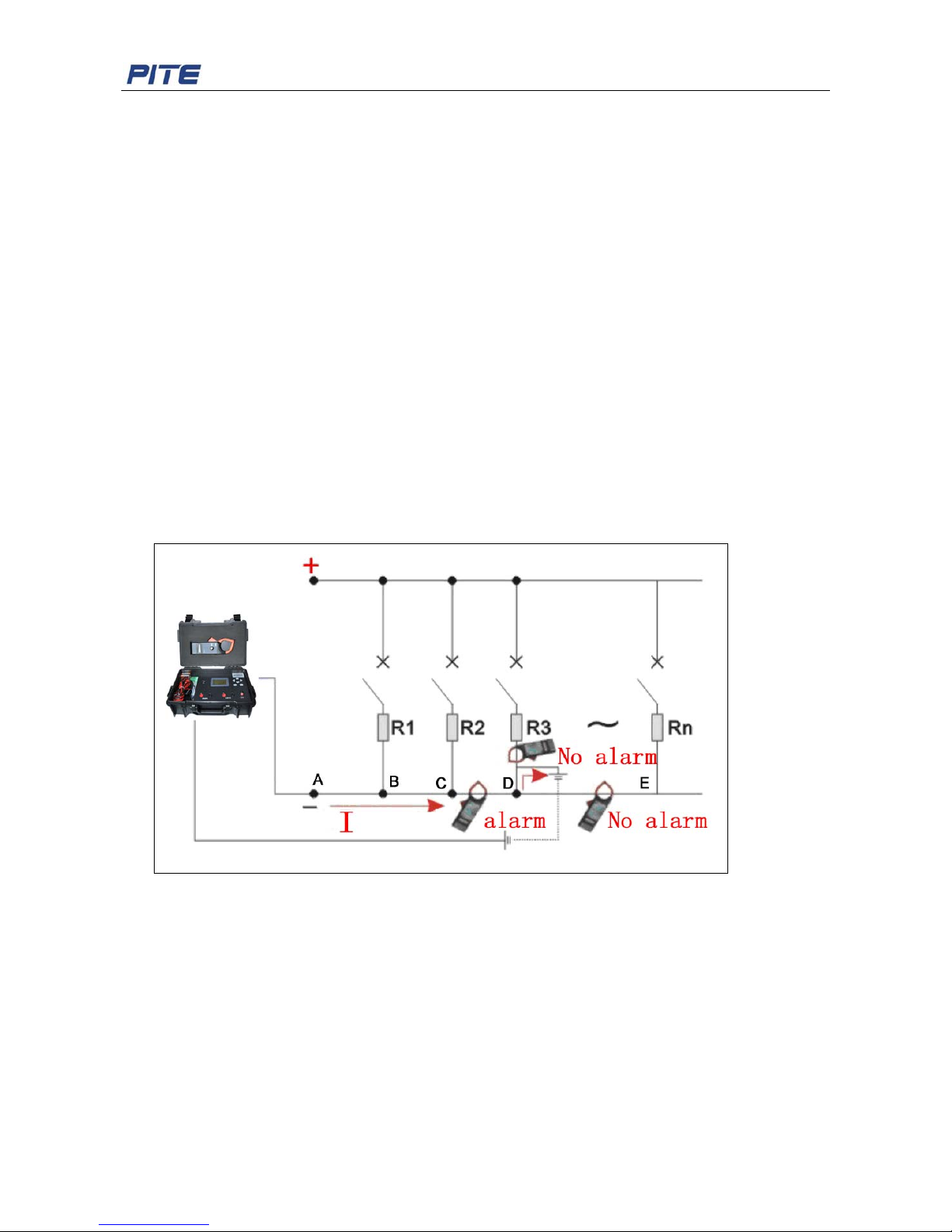
2.2.2 Connection for Grounding Location
In the function of ground fault location, main unit plays the role as signal generator. And grounding
receiver is the signal receiver. For its connection, please change the testing leads to the “Grounding”
socket in main unit. The testing alligators are the output ends of signal generator. They are connected
with busbar and ground. There are two different ways of connection based on which busbar has
breakage:
1). Red testing alligator is connected with positive busbar. Black alligator is connected with ground.
In this case, positive busbar has breakage.
2). Red testing alligator is connected with ground. And black alligator is connected with negative busbar.
In this case, negative busbar has breakage.
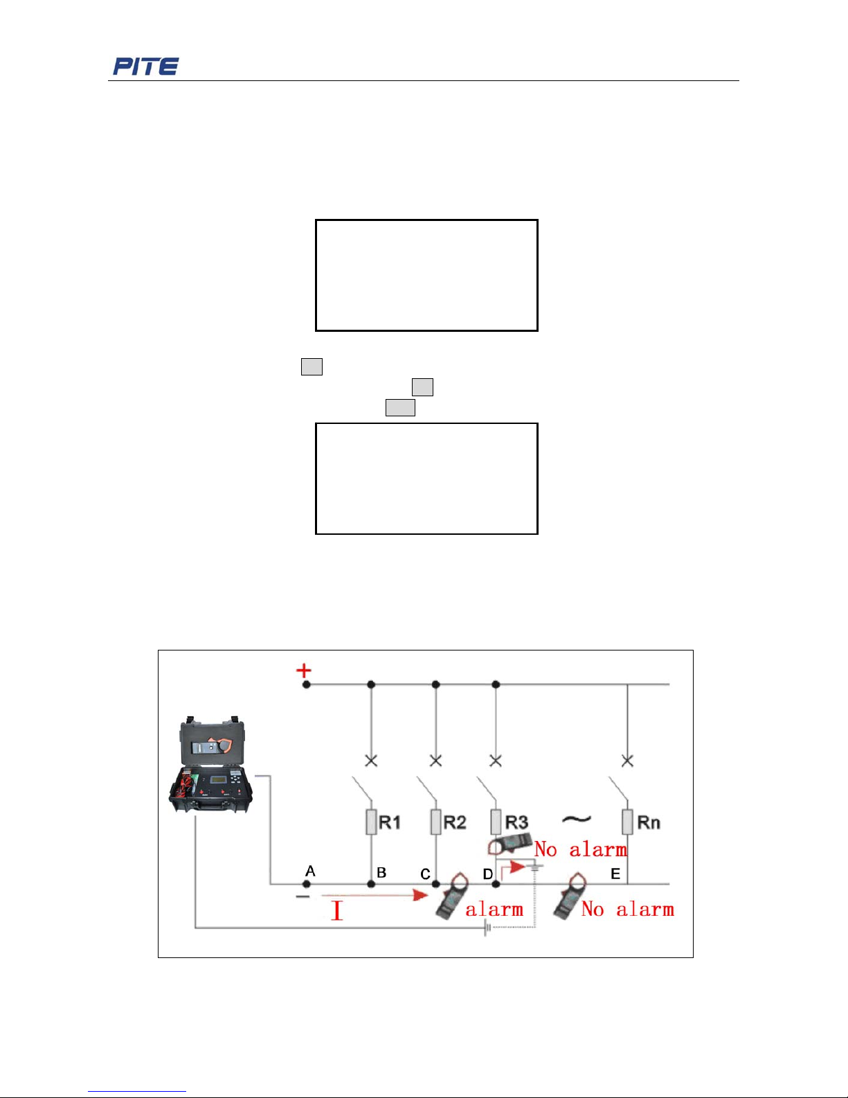
Wiring and operation flowchart for ground fault location is as below. We will describe this in details in
3.3 Ground-Fault Location.
Fig. 2.2.2
2.2.3 Other Connection
USB socket on the main unit panel is for connecting USB drive for data transfer and system update.
PITE 3830 contains rechargeable battery inside. For its changing, connect the battery charger (adaptor)
with the socket at the side of main unit case (see Fig 1.1.1).
2.3 Get Started
After connection is well done, switch on the main unit. If LCD screen is well displayed, then you could
start your testing by following this manual as below.
Page 9
PITE 3830 Ground-fault Locator User Manual
9
3. MAIN OPERATION
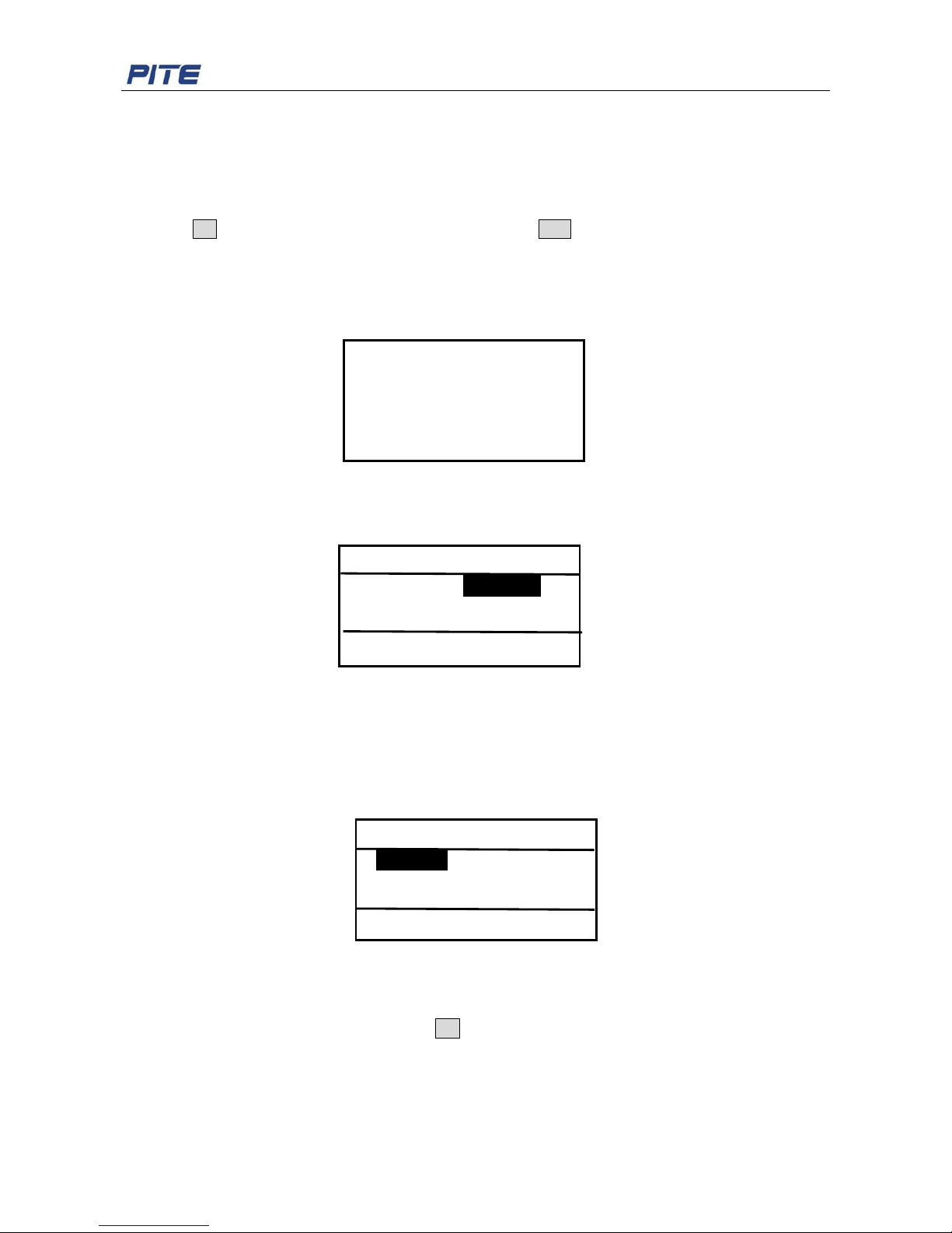
Arrow keys “↑”, “↓”, “←” and “→”are used to move up and down, generally for selection or number
changes. OK is for data saving or operation confirmation. ESC is for going back to upper menu or
canceling current operation.
3.1 Power On
After power is switched on, screen will display as below:
Fig.3.1.1
After about 1 second, screen will display the main menu automatically as below. Function of PITE 3830
includes Insulation test, Ground-fault location, Data management and System management.
Fig.3.1.2
3.2 Insulation Measurement
Make sure all testing leads and sockets are well connected. And select “Insul” in main menu. This
function contains two items, voltage testing and insulation measurement. Screen will be display as
below:
Fig.3.2
3.2.1 Voltage Testing
It will test the voltage between positive and negative binding posts. After the connection is done, select
“Test Volt” in the above menu and press OK to start the measurement of voltage. Below is the
example of testing result. Please make sure that the binding posts are correctly connected. Udc
indicates the effective value of DC voltage.
Insulation Test
Test Volt
Test Insul
-
-
Main Menu
Insul Gnd-fault
Data System
-
-
PITE 3830
Ground-Fault Locator
VER: 3.16
Page 10
PITE 3830 Ground-fault Locator User Manual
10
Fig. 3.2.1
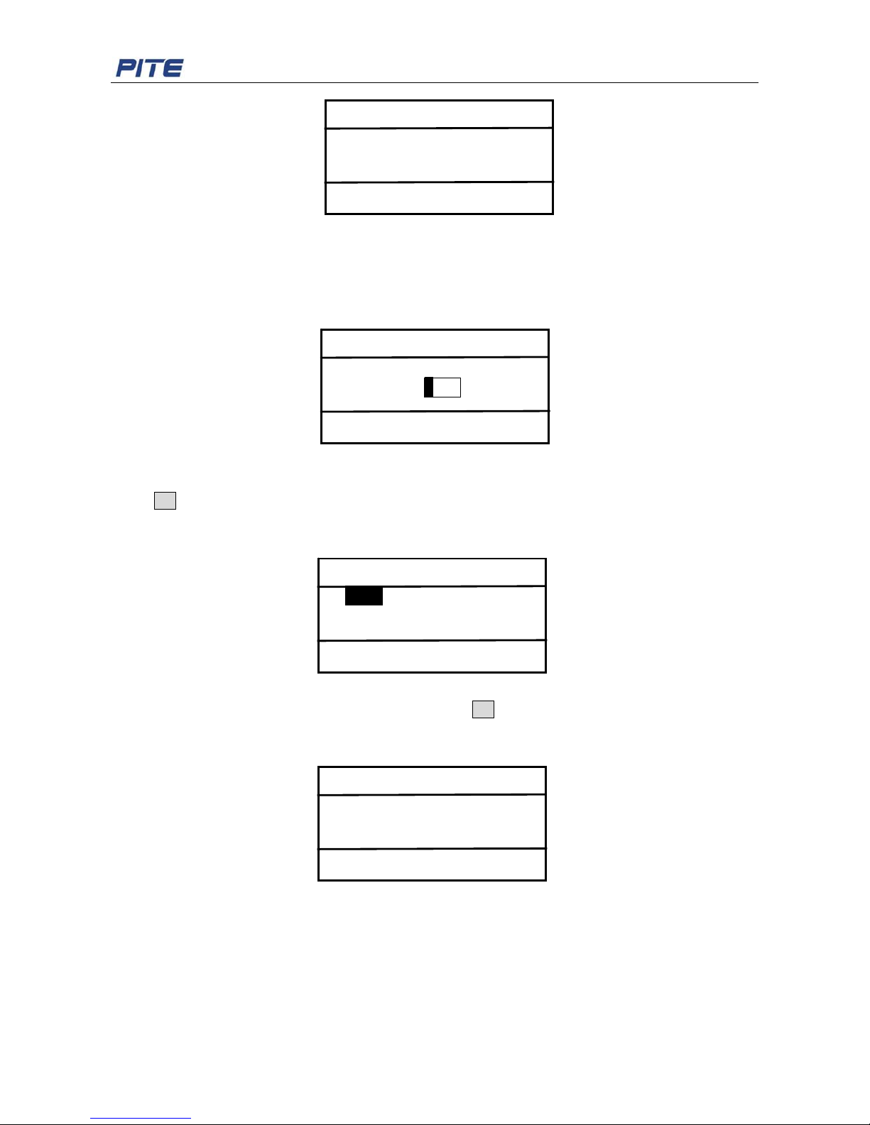
3.2.2 Insulation Measurement
Select “Test Insul” in insulation measurement menu. You will be required to input device number as
below. Use arrow keys for the setting of device number. This numbers are self-defined which could be
reviewed in the sector of data management.
Fig.3.2.2
Press OK to confirm the device number setting. You will then find 4 options for tested voltage: 100V,
500V, 250V and 1000V. These voltage levels are used in standard configuration of PITE 3830, other
voltage types could be made in specific units.
Fig. 3.2.2.1
Select the relative voltage for your circuit and press OK for confirmation. Positive and negative
Insulated binding posts will output the voltage as selected. Wait for a little while; you will see the
following screen. Resistance value indicates the testing result.
Fig.3.2.2.2
NOTE: Voltage injection is related to voltage-withstand of your testing target. Voltage input is always 2
to 3 times of nominal voltage. For example, if nominal voltage of testing target is 48V, you could select
100V in above option. If nominal voltage is 110V, you could select 220V. The higher voltage you select,
the higher accuracy you may get. However, at the same time, you may get testing target punctuated if
selected voltage is too high.
Pls select Volt
100V 500V
250V 1000V
OK or Exit?
Test volt
Vdc= 10V
Vac= 0V
<ESC> Exit
Pls input device No.
Device No.: 1000
OK or Exit?
Test Volt: 100V
R: >30MΩ
Save or Exit?
Page 11
PITE 3830 Ground-fault Locator User Manual
11
Output voltage of 100V maximally can measure insulation resistance of 30MΩ, 250V maximally 100MΩ,
500V maximally 200MΩ and 1000V maximally measures 2000 MΩ. Please select the proper output
voltage.
If the tested resistance is too low but the output voltage selected is higher than 250V, dielectric may be
punctured. Then you will see warning screen as below:
Fig. 3.2.2.3
After the measurement, press OK and you will find 6 options of loop to save the testing result. Use
arrow keys to select the relative one and press OK.Testing results could be reviewed in the menu of
data management. To cancel the test, press ESC and return to the upper menu.
Fig. 3.2.2.4
3.3 Ground-Fault Location
Connect the red and black testing leads with the grounding sockets in the main unit panel as described
in 2.2.2 Connection for Grounding Location.
Fig 3.3
After connections for testing leads and clips are done, select “Gnd-fault” in main menu to go to the
Pls select circuit
口 Main 口 Light
口 Auxili 口 Excita
口 Main/Auxss 口 1H
Insulation Puncture!
Page 12
PITE 3830 Ground-fault Locator User Manual
12
following step for parameter setting of output signal.
Fig.3.3.1
Default signal is 325Hz and 50V. This is the parameter of PITE’s signal receiver. If it’s 325Hz, then
select 325Hz. Voltage could be nearly the same like nominal voltage. If nominal voltage is 48V, you
could select 50V.
Press arrow keys of “←” and “→” to change the parameters if necessary. And press OK to enter screen
of grounding signal output like below:
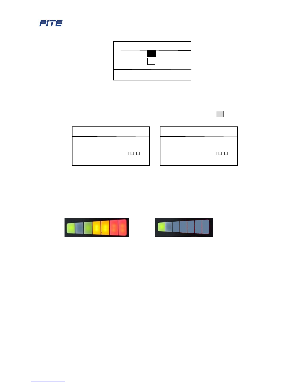
Fig. 3.3.2
You could press arrow keys of “←” and “→” to switch between different displaying models, discontinued
and continued (Fig.3.3.2). These two models could only be found when frequency is higher than 2.5Hz.
Then switch on the signal receiver. The receiver may indicate signal with red light and green light on the
right side flashing. This is caused by ambient signal interference. Just wait for a few seconds until these
lights are off like the following figures.
Î
Fig. 3.3.3
And adjust the signal input button (signal receiver) clockwise to adjust its sensitivity. It is more sensitive
at the end than the beginning.
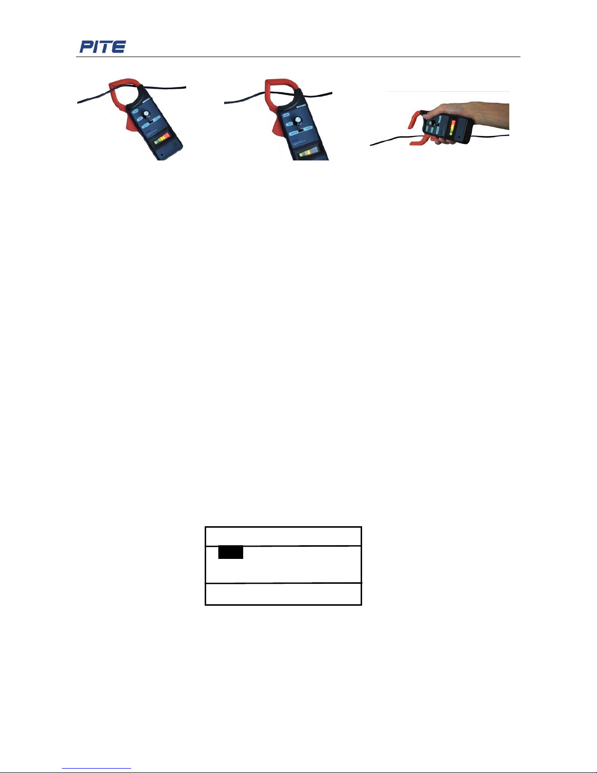
Open the receiver jaw, clamp around the busbar and move along the busbar (see Fig. 3.3 and Fig.3.3.4)
from A to B, C, D and E.
Two ways of signal indication:
1. Before the point of breakage, you will hear the sound warning from the signal receiver which is
close to the busbar. The sound will be either continuous or discontinuous based on above selection.
Take Fig 3.3 for example, if there is sound warning before Point D and no sound warning after Point
D, then there should be circuit breakage around Point D.
2. You could also see the signal difference on the signal indicator of receiver. After point of breakage,
signal is weak or no obvious signal at all. However, before the breakage, signal is flashing on the
receiver. This could be inspected even with the receiver is near the busbar with the jaw closed (Fig.
3.3.5).
Gnd sng output
Output Hz: 325Hz Disc
V: 56 V
I: 42.23mAR=1.3KΩ
Gnd sng output
Output Hz: 325 Hz Cont
V: 56 V
I: 42.23mAR=1.3KΩ
Param Setting
Output Hz: 325 Hz
Output V: 50 V
OK or Exit?
Page 13
PITE 3830 Ground-fault Locator User Manual
13
Fig. 3.3.4 Fig. 3.3.5 Fig. 3.3.6
NOTE:
1. You could either put the busbar across the clamp or put the clamp near the busbar (Fig. 3.3.6). In
this case, distance between busbar and clamp should be within 50cm. This is usually applied when
the busbar is buried underground and you know where it might be.
2. There is always sound warning between PITE 3830 and the point of breakage (e.g.: all the way
before Point D in Fig 3.3). After the point of breakage, there is no sound warning.
3. You may need to adjust the signal input button for sensitivity several times during the process. This
helps you narrow down and pinpoint the breakage.
Testing Tips:
1. To have clear sound warning, you could connect the earphone with the signal receiver and wear it.
2. To eliminate the faulty grounding, you could choose not to move the signal receiver from the
beginning of the busbar to the end. Take Fig 3.3 for example, you could narrow down by checking
Point A and then Point E. If there is sound warning in Point E, then continue to check points after
Point E. If there is no sound warning in Point E, then check other points between Point A and Point
E.
3. If there is more than one point that has breakage, please find them one by one.
3.4 Data Management
Select “Data” in main menu to enter the following screen. It contains 3 options for operation: Data
query (“View”), data delete (“Delete”) and transfer to USB drive (“To USB”)
Fig.3.4
3.4.1 Data Query
Select “View” in the above menu to enter the following screen. You have two ways to view the testing
data, either by condition or sequence.
Data manage
View Delete
To USB
Page 14
PITE 3830 Ground-fault Locator User Manual
14
By condition By sequence
Fig. 3.4.1
If by sequence, press arrow keys of “↑” and ”↓” to view different records. And press “←” and “→” to view
different loops.
3.4.2 Delete Data
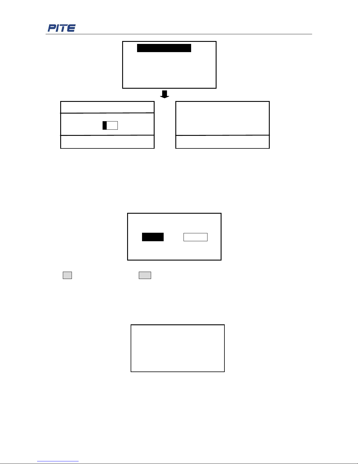
Select the option “Delete” in data management menu, you will see warning screen as below:
Fig. 3.4.2
Press OK to confirm the deleting or ESC to go back.
NOTE: Please keep the testing data properly. Once the data is deleted, it could not be recovered.
3.4.3 Transfer to USB Drive
Make sure the USB drive is well connected with the main unit panel, and select “To USB” in data
management screen. You will see the following screen for data saving.
Fig.3.4.3
After data is successfully saved in USB drive, remove it directly from the main unit. Data is saved with
the format “PITE3830.BAT” in the USB drive. This data could be analyzed on computer with PITE’s
data management software. For concrete instruction, please refer to 4. ANALYZING SOFTWARE.
Insulation Test
Device No.: 1000
OK or Exit?
Insul----condition
Insul----sequence
Device No.: 1000 Main
Insul R: 535.4KΩ
Test V: 100V
↑↓
Record →← Circuit
Sure to delete?
Cancel OK
Saving data…
Page 15
PITE 3830 Ground-fault Locator User Manual
15
3.5 System Management
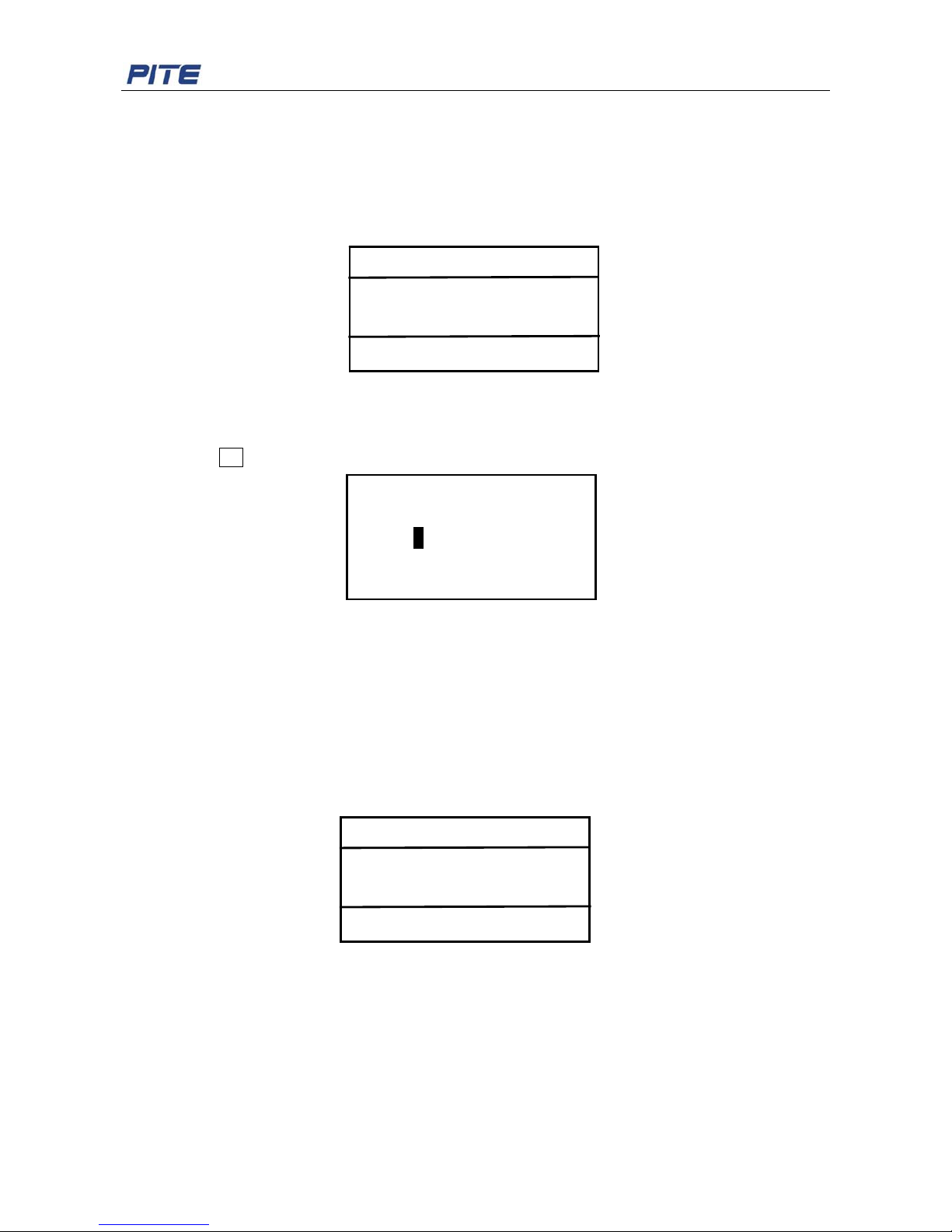
Return to main menu and select “Data” for system management. There contains 3 functions here: time
setting, calibration and system update.
Fig.3.5
3.5.1 Time Setting
Use arrow keys “←“ and ”→ “to move left and right. Use “↑” and ”↓“ to change the numbers. After the
setting, press OK to save the change.
Fig. 3.5.2
3.5.2 Calibration
WARN: Calibration is accuracy sensitive. It requires professional technique. All data has been
calibrated properly before this device is delivered to our customers. Please do not calibrate it unless
necessary. If you really need it, please contact PITE for assistance.
Here is one example for calibrating voltage.
Firstly select “Calib” in the menu of system management and input the password “8888”. The following
screen will be displayed. It includes calibration for external voltage, grounding and resistance.
Fig.3.5.3
Please follow the screen instruction for calibration.
In voltage calibration, positive probe of standard voltage meter should be connected with insulation
testing socket “+”, and negative probe with “-”. Please save the parameters only when the parameters
are stabilized, otherwise incorrect parameters will be saved and thus affect the measuring accuracy.
3.5.3 System Update
Operating program of PITE 3830 could be updated via USB drive. Please see below for the instruction
Time setting
2009 Y 12 M 17 D
18 H 19 M 52 S
System manage
Time Calib
Update
VER: 3.16
Calibration
External V Grounding
Resistance
OK or Exit?
Page 16
PITE 3830 Ground-fault Locator User Manual
16
of update:
1). Copy the latest program named “PROGDATA.BIN” to the root directory of USB drive and insert the
USB drive into PITE 3830 main unit.
2.) Enter “System” in main menu, select “Update” and input password “8888”.
3). Press OK and hold for 6 seconds and you will see “Programming…”.
4). After the program is successfully updated, screen will automatically return to the main menu.
NOTE:
1). If there is no display of “Programming…”, system is not updated. Please make sure there is a file
named “PROGDATA.BIN” in the USB drive. Sometimes, you need to format the USB drive first and
then copy the file to the root directory of USB drive.
2). In case of problem (power off or USB drive is loose) during the system update, please turn off the
main unit, press the key OK for a while (not release) and at the same time restart the main unit. Then
you will also enter update mode.
4. ANALYZING SOFTWARE
This is the data management software for PITE 3830 Ground Fault Locator (hereinafter Locator). With
this software, you could backup, save and recover the testing data by using the database. Measuring
data could be transferred to a personal computer via USB drive for data analyzing. Before data
analyzing, the following analyzing software should be installed in the PC.
4.1 Software Installation
1) Start up your PC
2) Close all application running on the computer (recommended).
3) Insert the CD for Analyzing Software into CD-ROM drive of PC.
4) Once the computer detects the CD-R, find the Locator Data Management System—Ground Fault
Locator.exe, and then double click the file named “Ground Fault Locator” to start the installation.
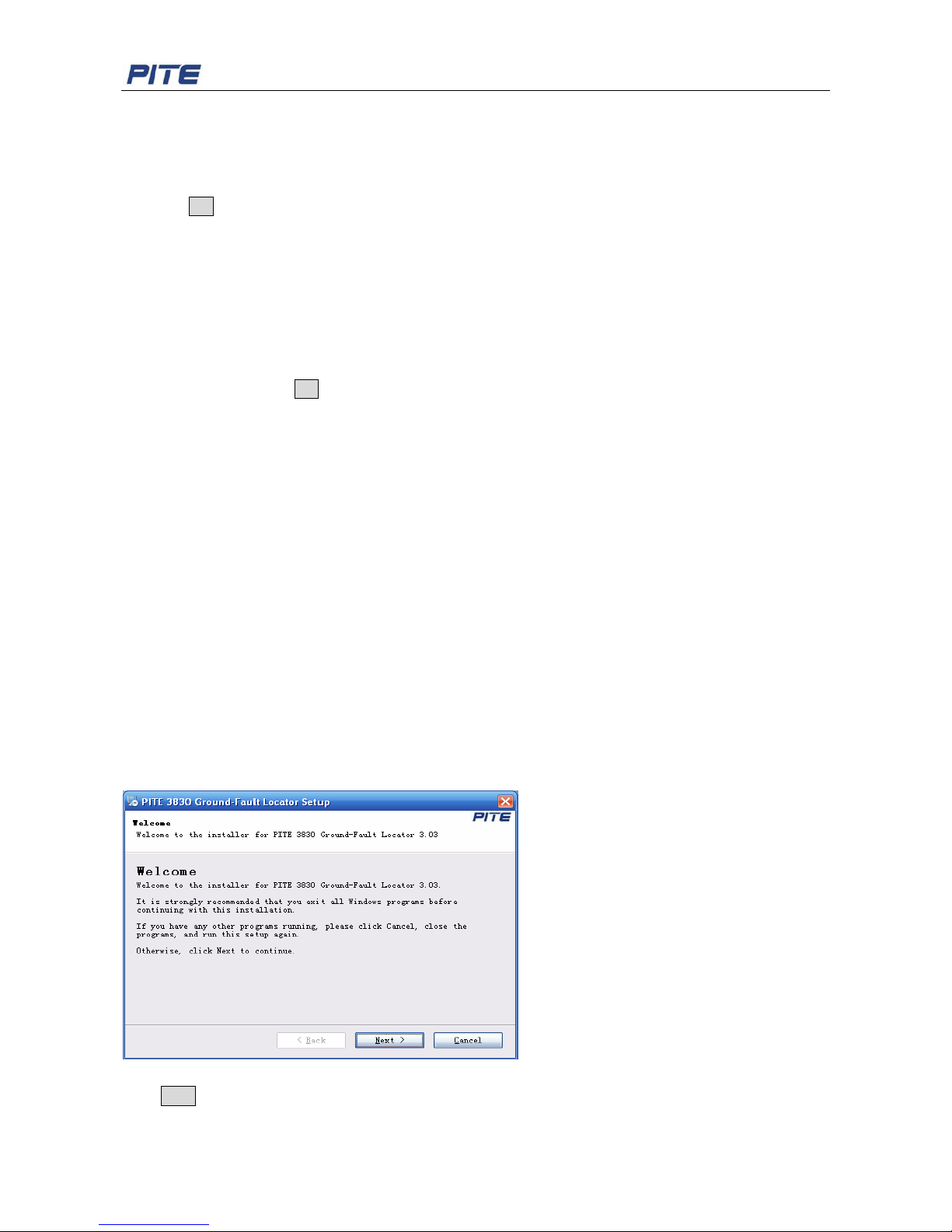
Installation screens will be showed as below.
Fig 4.1.1
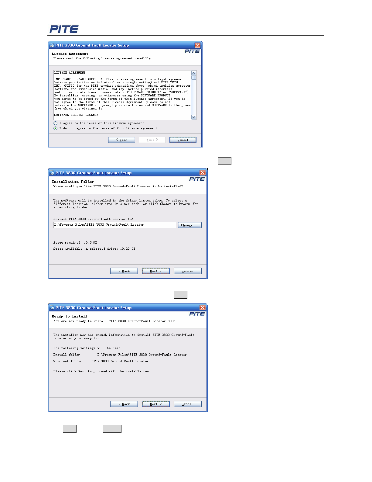
Click Next to go to the following screen:
Page 17
PITE 3830 Ground-fault Locator User Manual
17
Fig 4.1.2
Select “I agree to the terms of this license agreement” and click Next to go to the following step:
Fig 4.1.3
Change the installation path if necessary. Click Next and you will come to this step:
Fig 4.1.4
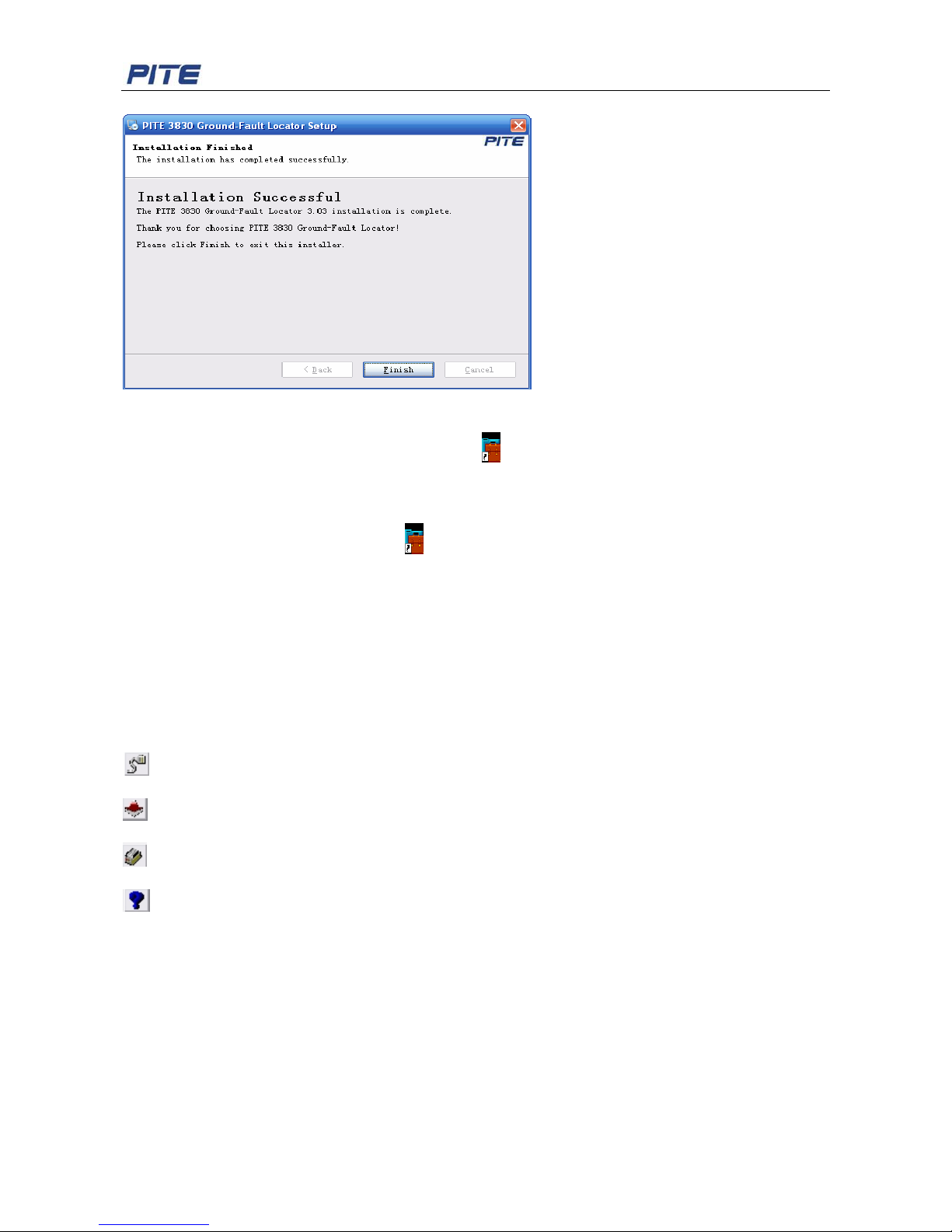
Click Next and then Finish as screen below to complete the installation:
Page 18
PITE 3830 Ground-fault Locator User Manual
18
Fig 4.1.5
After installation is done, you will see the icon
E 3830 Gro...l
on the desktop. If you could not see it on
desktop, find it in “Start” menu. Follow the screen instructions to install the program. After installation,
you will find PITE 3830 program icon
E 3830 Gro...l
on the PC desktop.
4.2 Software Operation
This Data Management System is applied to PITE 3830 Ground Fault Locator. You could save, delete
or print testing and analyzing data as per your need.
Four hot keys under the toolbar are for shortcut operation with definition as below:
: Received Data. Click the button and then the window of Read File will pop up.
: Update Program.
: Insul Test. Click the button and then the window of Insul Test will pop up.
: About. Click the button and then the window of About will pop up.
To start the analyzing software, please go step by step as below:
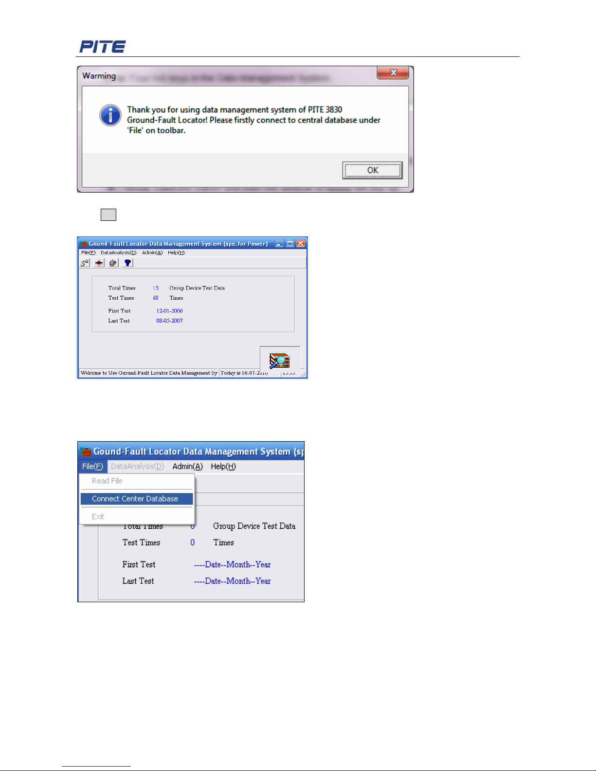
1. Double click the icon on the desktop. A Window will pop up to remind you connect to central
database under ‘File’ on toolbar first. This database will be used to save the data when this
analyzing software is used.
Page 19
PITE 3830 Ground-fault Locator User Manual
19
Fig 4.2.a
Click OK to start.
The Data Management window will pop up as below:
Fig 4.2.b
NOTE: Some functions are not active until the database is connected.
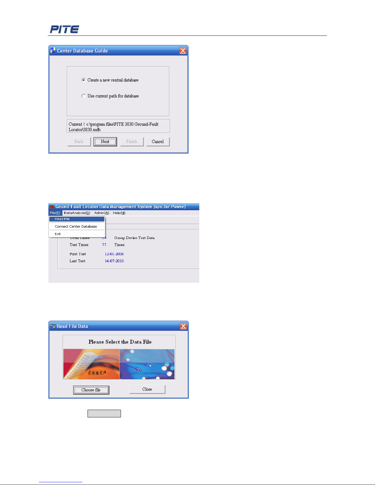
2. Click “File” and then “Connect Center Database” as below for database setting.
Fig 4.2.c
Select either way below to orient a path for the database. Only after database is connected can you
carry other function like data analyzing.
Page 20
PITE 3830 Ground-fault Locator User Manual
20
Fig 4.2.d
You will see details of connect center database in 4.2.1- 2).
4.2.1 File Processing
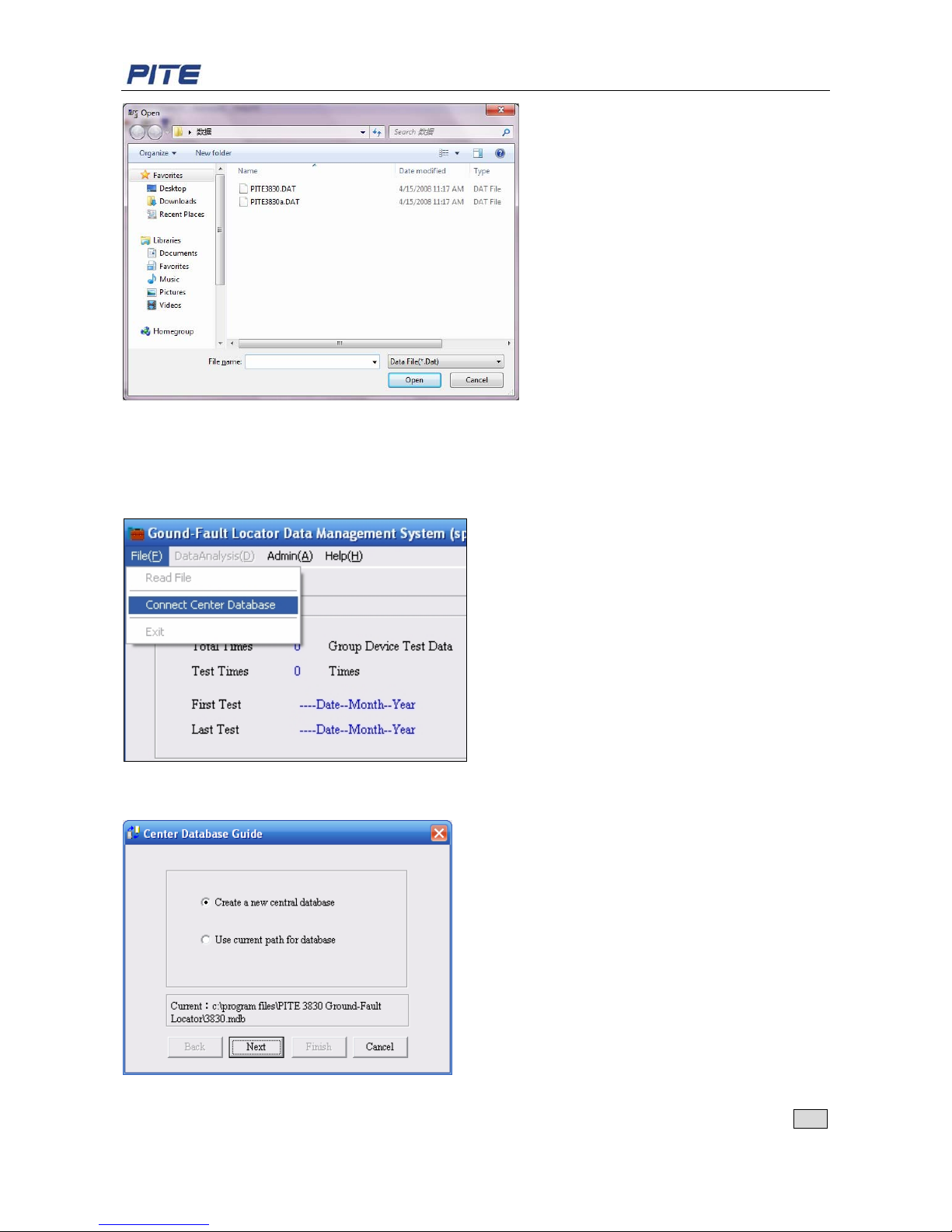
It includes three functions of “Read File”, “Connect Center Database” and “Exit”
Fig 4.2.1.1
1) Read File
It uses to read the measuring data you stored in the USB drive.
Click “File” and then “Read File”, and you will go to the following screen. See the screen as below:
Fig 4.2.1.2
Then click the Choose file button, you will see the screen as below:
Page 21
PITE 3830 Ground-fault Locator User Manual
21
Fig 4.2.1.3
Select the Data and the data will be saved automatically.
2) Connect Center Database
The operation is the same as above. See the 4.2-1
Click “File” and then “Connect Center Database”. See the following screen:
Fig 4.2.1.4
Then enter into the window of Center Database Guide. See the screen as below:
Fig 4.2.1.5
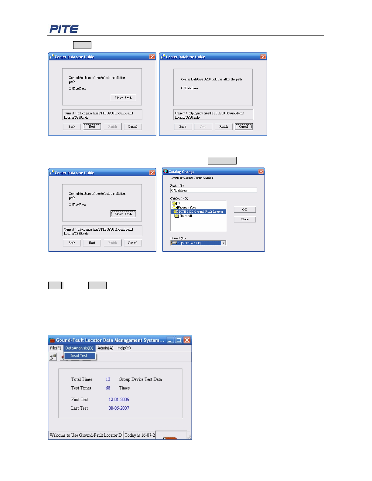
If it is the first time for installation, please select “Create a new central database” and then click Next
Page 22
PITE 3830 Ground-fault Locator User Manual
22
and then Finish to create a new center database.
Fig 4.2.1.6 Fig 4.2.1.7
Users can alter the center database path if necessary. Click Alter Path to choose the correct path.
Fig 4.2.1.8 Fig 4.2.1.9
If it is not the first time for installation, users can select “use current path for database” and then click
Next and then Finish to connect the current database.
4.2.2 Data Analysis
Data Analysis is for insulation test. It uses to analyze the insulation measuring data saved in the
database.
Insulation Test
Page 23
PITE 3830 Ground-fault Locator User Manual
23
Fig 4.2.2.1
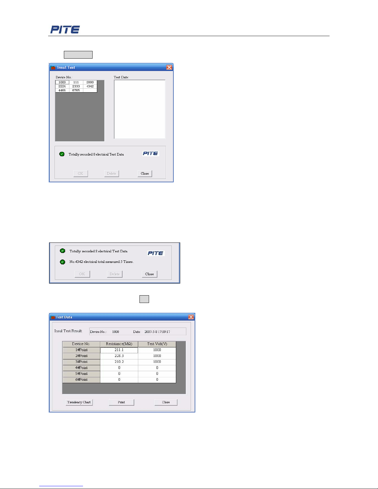
Click Insul Test, the screen of insul test is seen as below:
Fig 4.2.2.2
Device No.: The number of total devices which the Locator has tested.
Test Date: The date in which the device has tested by the Locator.
Click the specified device No. and then the test data will be showed on the right window of Test Date.
The total number of tested device and the total time of each tested device are showed at the window
below. See screen:
Fig 4.2.2.3
Click the specified date and then OK or double click the specified date, a window of the test data of the
specified device in the current date will pop up like the screen:
Fig 4.2.2.4
The resistance and test voltage of each point of the device will be showed in the test report.
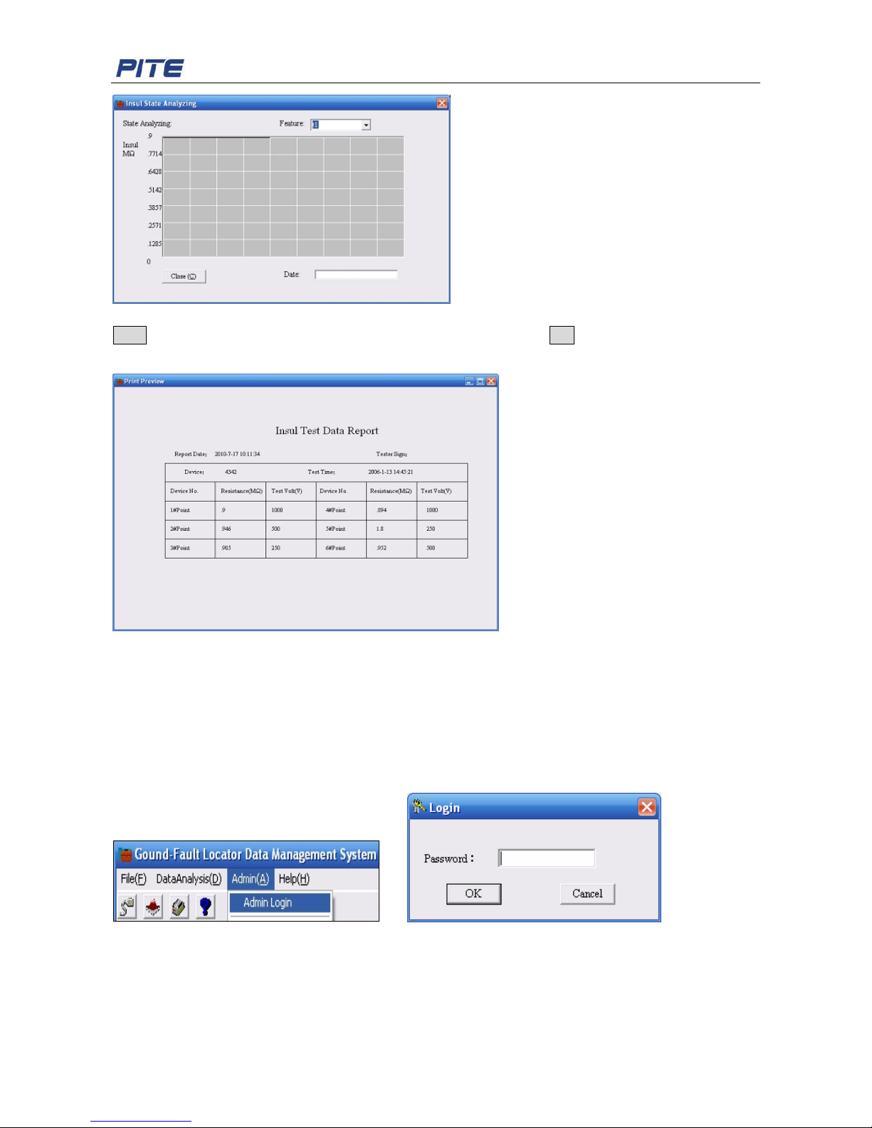
Click the button of Tendency Chart and then a screen of state analysis of the insul test will be showed.
See screen:
Page 24
PITE 3830 Ground-fault Locator User Manual
24
Fig 4.2.2.5
Print: The insul test report can be printed if click the button and then Yes . The screen of printed report
is like this below:
Fig 4.2.2.6
4.2.3 Administrator
The administrator password of the system is 26880310. For sure the safe of your measuring data,
please take good care of your password.
1) Administrator Login
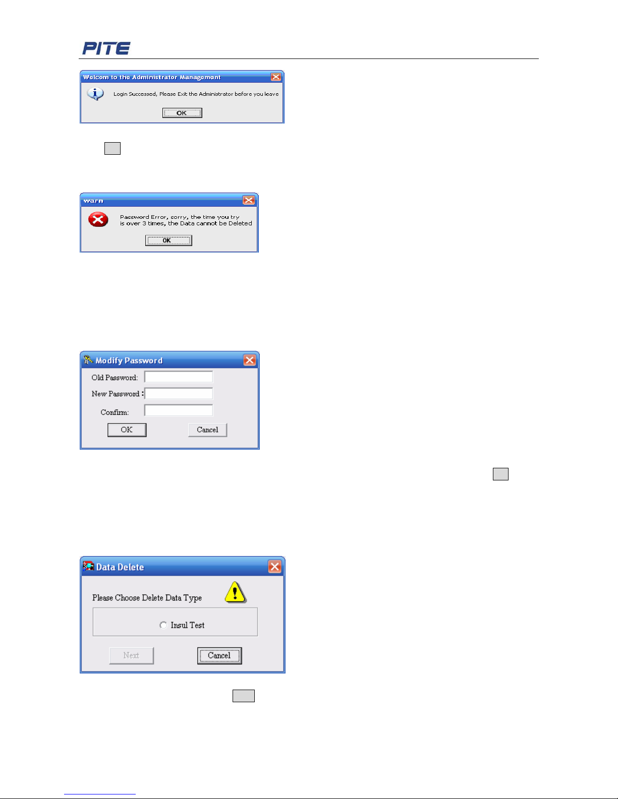
Click the “Admin” and then “Admin Login”, a window of password input will pop up like this:
Fig 4.2.3.1 Fig 4.2.3.2
Input the password 26880310 and then a window of warming will pop up. See screen:
Page 25
PITE 3830 Ground-fault Locator User Manual
25
Fig 4.2.3.3
Click OK and you will log in the administrator.
Warming: In order to protect the rights of administrator, the password input can be tried no more than
three times. If a warming window like below pops up, please restart the system and then try it again.
Fig 4.2.3.4
Note: data delete is the function special for administrator. The data cannot be deleted only login the
administrator.
2) Modify Password
Password can be modified in the following screen only after you log in the administrator.
Click “Admin” and then “Modify Password”, a screen will be showed as below:
Fig 4.2.3.5
Please input the old password, then new password twice and confirm by clicking the button OK. Then
the password will be modified successfully.
3) Delete Data
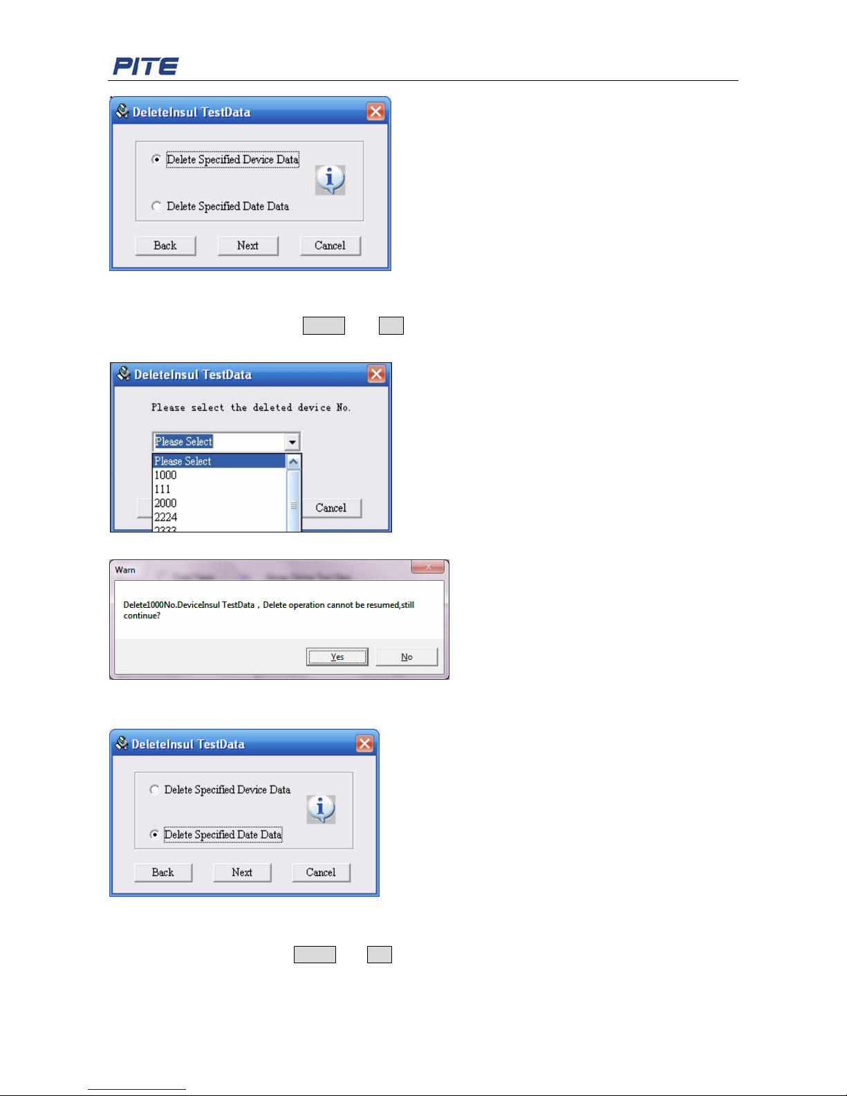
The test data can be deleted only after you log in the administrator. It contains two types of data delete:
delete specified device data and delete specified date data.
Click “Admin” and then “Delete Data”, a screen of delete data will be showed as below:
Fig 4.2.3.6
Select “Insul Test”, and then click Next
1. Delete Specified Device Data
Page 26
PITE 3830 Ground-fault Locator User Manual
26
Fig 4.2.3.7
The function is used to modify the number of a tested device.
Select a device and then click Delete and Yes, the total test data of the device will be deleted. See
screen as below:
Fig 4.2.3.8
Fig 4.2.3.9
2. Delete Specified Date Data
Fig 4.2.3.10
The function is used to delete the data of specified time in which a device is tested.
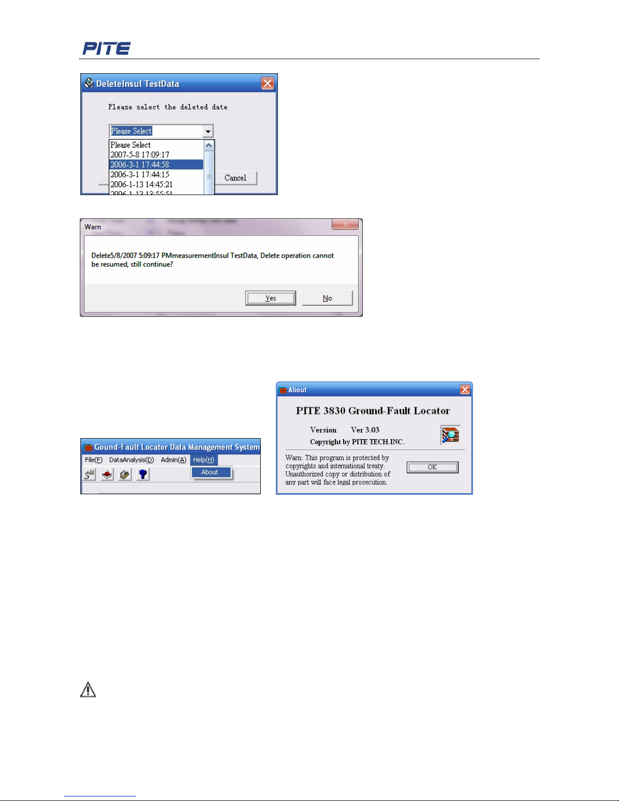
Select the date and then click Delete and Yes, the total data of the date will be deleted. See screen as
below:
Page 27
PITE 3830 Ground-fault Locator User Manual
27
Fig 4.2.3.11
Fig 4.2.3.12
4.2.4 About
Click “Help” and then “About”, then a screen of the information of Locator will be showed as below:
Fig 4.2.4.1 Fig 4.2.4.2
5. SERVICE & MAINTENANCE
5.1 Cleaning
Clean PITE 3830 main unit and its accessories with soft damp cloth and a mild cleaner. Do not use
abrasives, solvents, or alcohol, as they can deform or discolor the Locator and the accessories.
After cleaning voltage testing clip with software cloth, clean it again with water and wipe it. Do not
damage the metal part of the clips to ensure its accurate performance during testing.
WARNING: For your own safety, make sure that the main unit and accessories are not working and
disconnected from the power supply before cleaning.
Page 28

PITE 3830 Ground-fault Locator User Manual
28
5.2 Storage
After using PITE 3830, put the main unit and all its accessories into the carrying case, store the case in
ventilating place under proper temperature and humidity. Never expose the Tester and its accessories
to water, high humidity, or dampness. If not used for some time, the Li-battery will discharge itself
gradually. To keep its best performance, you are suggested to charge the battery periodically, like once
a month.
6. FAQ
Q: Testing data has big error
A: Please check if battery and main unit are well connected. If not, correct it.
Q: Screen has no display after power on.
A: Please check if battery is power off. If so, charge it before testing.
Q: Keyboard becomes invalid or mixed up.
A: Please check if buttons are stuck in the key hole. If so, put them to pop up.
Q: Data management software could not get data.
A: Please check if network work fine or management software is properly installed.
7. ORDER INFORMATION
PITE TECH. INC.
4/F, Bldg A, Chiwan Industrial Park, Shaodi Rd., Chiwan, Shekou Area, Shenzhen, China
TEL: +86-755-2680 5759 FAX: +86-755-2688 0310
www.pitetech.com
 Loading...