

Page 1

PITE 3561 Power Quali ty Analyzer
User Manual
P-120907-V1.4
4/F, Bldg A, Chiwan Industrial Park, Shaodi Rd.,
Chiwan, Shekou Area, Shenzhen, China
TEL: +86-755-2680 5759
FAX: +86-755-2688 031 0
www.pitetech.com
Page 2

PITE 3561 Power Quality Analyzer
2
Catalogue
1. INTRODUCTION ............................................................................................................. 3
1.1 Packing List ............................................................................................................ 3
1.2 Safety Information .................................................................................................. 4
1.3 Operating Precautions ............................................................................................ 5
2. OVERVIEW ...................................................................................................................... 5
2.1 About PITE 3561 .................................................................................................... 5
2.2 Functions ................................................................................................................ 6
2.3 Features.................................................................................................................. 6
2.4 Technical Parameters ............................................................................................. 7
2.5 Definition of Abbreviation ........................................................................................ 8
3. MEASUREMENT PREPARATION .................................................................................. 9
3.1 Battery Charging..................................................................................................... 9
3.2 Cable Connection ................................................................................................... 9
3.3 Analyzer Power-on ............................................................................................... 10
4. MEASUREMENT ........................................................................................................... 10
4.1 Volts/ Amps/ Hertz ................................................................................................ 11
4.2 Harmonics ............................................................................................................ 12
4.3 Power & Energy .................................................................................................... 13
4.4 Unbalance ............................................................................................................ 14
4.5 Record .................................................................................................................. 14
4.6 Fluctuation/ Flicker ............................................................................................... 15
4.7 Dips/ Swells .......................................................................................................... 16
4.8 Inrush .................................................................................................................... 16
4.9 Scope .................................................................................................................... 17
5. SYSTEM MANAGEMENT ............................................................................................. 18
5.1 Data Management ................................................................................................ 18
5.2 System Setting ..................................................................................................... 19
5.2.1 Calibration .................................................................................................. 19
5.2.2 Parameter Setting ...................................................................................... 19
5.2.3 Date & Time................................................................................................ 19
5.3 Language Setting ................................................................................................. 20
5.4 Voltage Color Setting ............................................................................................ 20
5.5 Phase Angle Setting ............................................................................................. 20
5.6 Firmware Ver sion and Upd ate .............................................................................. 21
6. SERVICE A ND MAINTENA NCE .................................................................................. 21
6.1 Maintenance ......................................................................................................... 21
6.2 FAQ ....................................................................................................................... 22
7. PITE 3561 DATAVIEW SOF TWARE ............................................................................. 22
7.1 Software Installation ............................................................................................. 22
7.2 Software Operat ion ............................................................................................... 23
8. ORDER INFORMATION................................................................................................ 26
Page 3
PITE 3561 Power Quality Analyzer
3
1. INTRODUCTION
This Users Manual gives full in formation o n how to us e PITE 3561 Pow er Qual ity Analyz er
(hereinafter called “Analyzer”) safely and effectively . Pl eas e r ead the manual carefully so
as to obtain maximum perfor ma nce of the analyzer and its accessories.
IMPORTANT: Please read this manual completely before connect ing and po wering on the
analyzer to avoid possible damage caused by improper use of this instr ument.
1.1 Packing List
After receiving the analyzer, please check it carefully as below:
Ensure that no damage occurred during transportation. Upon any damage or failure
of operation based on this instr ument, please contact y our supplier immediately.
Make sure you have each items below:
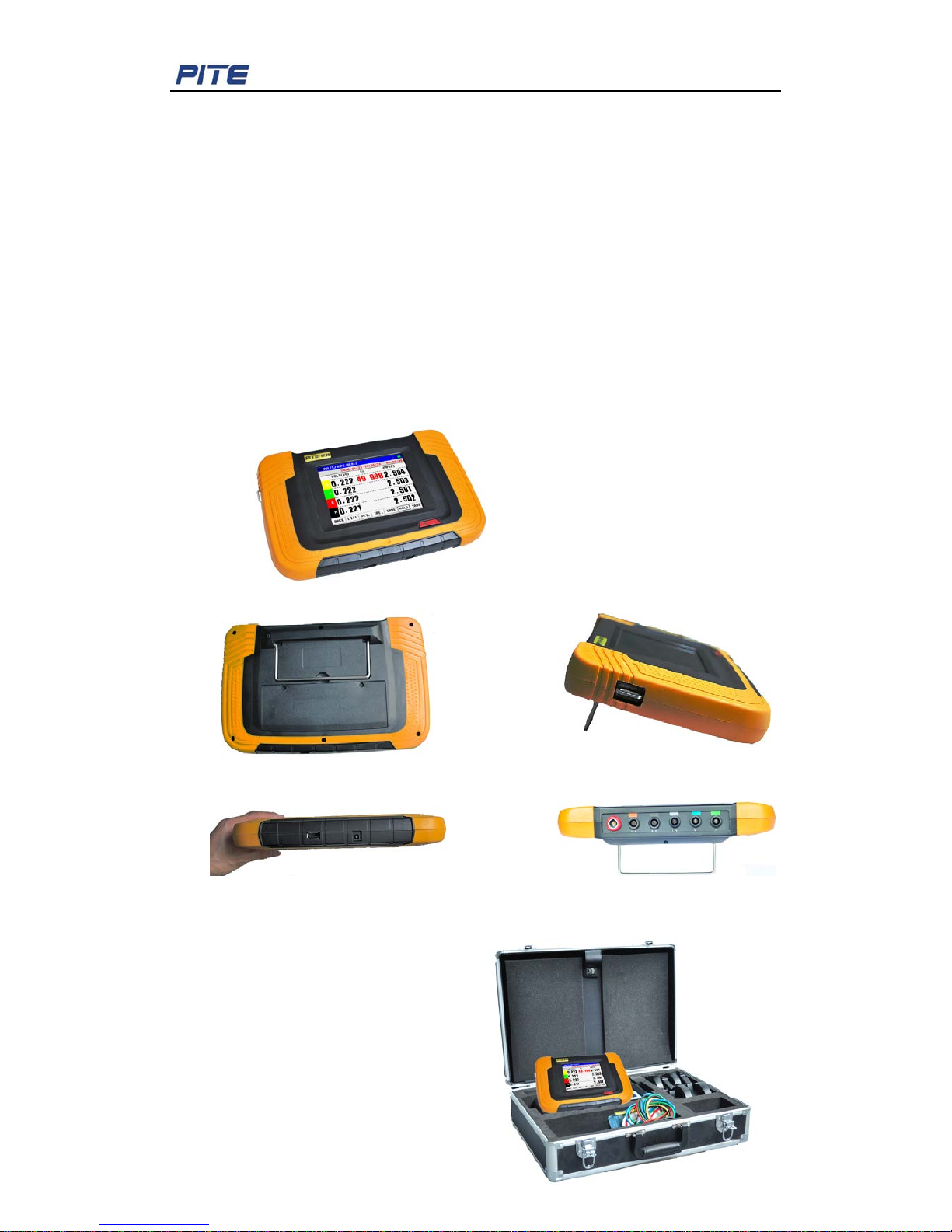
1) Main unit
All sides of PITE 3561 main unit:
Back Side (with belt buckle)
Bottom (1 USB socket and 1 pow er socket) Top (6 connecting sockets)
Fig. 1.1.1 PITE 3561 Main Unit
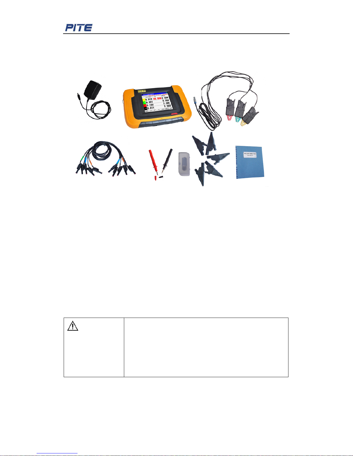
2) Accessories:
①. User Manual (this manual, 1)
②. Power Adaptor (1)
③. Voltage Test Leads (5)
④. Standard Current Cla mp s* (3)
⑤. Alligator Clips (5)
⑥. USB drive (1)
⑦. Voltage Probes (2)
Page 4
PITE 3561 Power Quality Analyzer
4
⑧. Carrying Case (1)
Sample picture of PITE 35 61 accessories:
Fig.1.1.2
*Note:
1) About sample picture is just for your reference. Current clamps may differ as per
different customers.
2) Standard PITE 3561 units w ill come with 3 current clamps. Optional curr ent clamp
below 100A for neutral will be available upon request.
1.2 Safety Information
For your protection, please read this safety information completely before operating the
analyzer. Carefully observe all warnings, pr ecautions and instructions.
Warning: Servicing described in this manual is to be done only by qualified service
personnel. To avoid electrical shock, do not service the instrument unless you are
qualified to do so.
DANGER
Safety tested has been done on this instrument thoroughly
before shipment. However, mishandling during use could result
in injury or death, as well as damage to the instrument. Make
sure that you understand the instructions and precautions in
the manual before use. We disclaim any responsibility for
accidents or injuries not resulted
directly from instrument
defects.
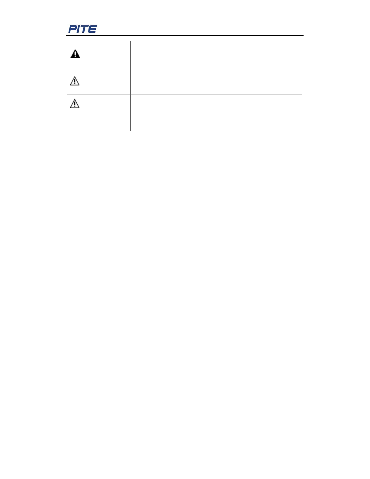
Safety Symbols:
The following symbols are used on the instrument and in this manual.
Page 5
PITE 3561 Power Quality Analyzer
5
DANGER
Indicates correct operation to prevent an extreme hazard that
could result in seri
ous injury or other bad consequences to
users.
WARNING
Indicates correct operation to prevent a significant hazard that
could result in serious injury or other bad consequences to
users.
CAUTION
Indicates correct operation to prevent possible injury to users
or damage to the instrume nt .
NOTE
Indicates advisory items related to performance or correct
operation of the instrument.
1.3 Operating Precautions
To avoid electrical shock or fire, r ead these precautions first before us in g t he analyzer:
Avoid working alone.
Do not operate the Analyzer ar ound explosive gas or vapor.
Use only insulated current pr obes, t est leads and adapters as supplied with the
Analyzer.
Before use, inspect the Analyzer, voltage probes, test leads and acce ssories for
mechanical damage and r epl ace whe n da mage d. Lo o k for crac ks or miss in g plastic.
Pay special attention to the insulation surrounding the connectors .
Remove all probes, test leads an d ac cessories that are not in use.
Always connect the Battery Charger / Power Adapter first to the AC outlet before
connecting it to the Analyzer.
Use the ground input only to ground the Analyzer and do not apply any voltage.
Do not apply input voltages above the rating of the instrument.
Do not apply voltages in excess o f t he marked ratings of the voltage probes or
current clamps.
Do not use exposed banana pl ug connectors.
Do not insert metal objects into connectors.
Use only the power supply, Model PITE 3561 (Battery Charger / Power A dapter).
Before use, check that the selected/indicated voltage range on the PIT E 3561
matches the local line pow er voltage and frequency.
For the PITE 3561, use only AC line plug adapt ers or AC line cord s that comply w ith
local safety regulations.
2. OVERVIEW
2.1 About PITE 3561
The Analyzer offers exten sive and powerful measurement to chec k pow er distribution
systems. It provides measure ment for harmonic, power & energy, unbalance, dips &
swells, flicker and so on. Thus it gives a general analysis for system performance an d
specific details. Testing result could be read on the instrument directly and also uploaded
Page 6

PITE 3561 Power Quality Analyzer
6
to a personal computer via a USB drive for further analysis.
2.2 Functions
PITE 3561 provides compr ehensive functions for power quality analy zing as below:
Volts/Amps/Hertz
It gives a fast overview of Volt s, Amps an d Hertz . Use this fu nction to g et a first impre ssion
of the voltage and current signal before examining the signal in more details.
Harmonic
Use Harmonic mode to chec k voltage and current harmonics and THD per ph ase. It can
check up to 50
th
harmonics. Trend of harmonics could also be recorded.
Power & Energy
It displays active power (W), appar ent pow er (VA), reactive power (VAR) and power factor
(PF) of balanced 3-phase, 3-wire power systems
Unbalance
Each phase voltage shoul d not di ff er m or e t han 1 % from the average of the three.
Current unbalance should not exceed 10 %. Use Scope Phase or Unbal ance mode to
investigate unbalances.
Dips & Swells
Use Dips & Swells to record transient changes of voltage
Fluctuation & Flicke r
Use Flicker testing to check short and long term volt age fl icker a nd re lated d ata per pha se .
Records
In this mode, you will find complete records of previous testing for voltage, current,
frequency, power, power factor , total voltage harmonics dist or t i on (THD), total current
harmonics, and fluctuatio n & flicker results.
Scope
It shows voltage and current signal.
2.3 Features
♦ Portable design and colorf ul t ouch screen
♦ Applied to standard of EN 5016 0
♦ Could test 3-phase volt, n ull li ne volt, 3-phase current, null line current, et c.
♦ Up to 50 times harmonic test ing with frequency spectrum graph
♦ Power testing: 3-phase ap par ent power, active power, reactive power, power factor,
and 3-phase electric power.
♦ 3-phase unbalance testin g with vivid chart
♦ Record at least 40 times of surge c ur r ent
♦ Testing for wave motion, short-time flicker and long-time flicker
♦ Record up to 40 times of s ag and swell
♦ Could have long-time rec ord for basic (stable) power quality param et er . Recording
time interval adjustable between 3 second and 30 minutes.
♦ Digital oscilloscope, checking waveform for voltage and curre nt s ign al
♦ With PITE DataView software for convenient analyzing of testing result
Page 7
PITE 3561 Power Quality Analyzer
7
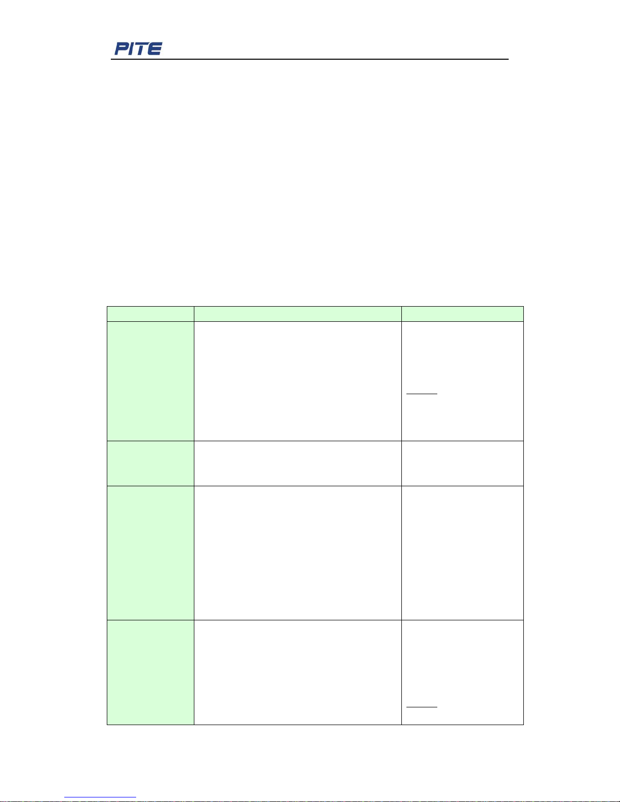
2.4 Technical Parameters
LCD screen: 320 x240 TFT
Input Impedance: 1MΩ,20pF
Measurement Range:10 ~700Vrms
Arms:1A,10A,100A,1000A and higher w ith r elative current clamps)
Frequency 30Hz~80Hz
Harmonic Measurement : 0~50th harmonic
Inrush Current: 2000A
Peak Volt ag e: 1000V
Internal Memory: 128Mb
LCD Display: 320*240 pix el, t ouch screen
Communication Port: US B
Net weight: 7 kg
Other specifications:
Specifications
Range
Accuracy
Volt/Amp/
Hertz
Volt: 10~ 700V (true rms)
Amps: 0.5~3000A (true rms, with relevant
current clamp) N current: 0.5~25A (true
rms)
Current Peak: 0-3000A
Volt Peak: 0-1000V
Crest factor: 0-10
Hertz: 40~70Hz
Volts: ±0.5%
Amps: ±0.5%
Hertz: ±0.01Hz
NOTE: Take frequency of
L1
as total testing
frequency.
Harmonic
Volts: total harmonic +1~50t h
Amps: total har mo ni c + 1~ 50th
k-factor: 0-10
Volts: ±0.1(%r)
Amps: ±1%
±0.5%
Power testing
Active Power: 0.05~700K W
Apparent Power: 0.05~ 700KV A
Reactive Power: 0.05~700KVAR
Power Factor: 0.00~1.00
Active Energy: 0.01~1000 0kWh
Apparent Energy: 0. 01~ 10000kVAh
Reactive Energy: 0.01~10000kVARh
Average Power Factor : 0. 00~ 1.00
Active Power: ±1%
Apparent Power: ±1%
Reactive Power:±1%
Power Factor: ±0.005
Active Energy: ±1%
Apparent Energy: ± 1%
Reactive Energy: ±1%h
Average Power Factor:
±0.005
Unbalance
Fundamental Volts: 10~700V (t r ue r m s)
Fundamental Amps: 0.5~1 000A (True rms)
Fundamental Hertz: 40~70Hz
Phase Angle:-180
o
-180 o or 0~360o
Unbalance: 0.0%~100%
Volts: ±0.5%
Amps: ±0.5%
Hertz: ±0.01Hz
Phase Angle: ±0.3
o
Volt un balance: ±0.2%
NOTE: Take frequency of
L1 as total testing
Page 8
PITE 3561 Power Quality Analyzer
8
frequency.
Data Recordin g
Recording for: 3 phase voltage, current, null
current, voltage harmonic (THD and 1~25
harmonics), current harmonics ( THD and
1~25
harmonics), unbalance, KW,
KVA,KVAR, PF, flicker and flu ct uation
Time interval: 3s~30min
adjustable
Time duration: <960
hours
Sags(Dips)/Swe
lls
Volts sag, Volts Swells and instant
interruption
Maximally could record
40 times
Fluctuation
Volt age Flu ctuati on:0. 1%~ 10.0%
≤
±5%
Flicker
Short-time and long-time flicker
Short-time: ≤±5%
Scope
3-phase Volts, 4-wire Current, null volt and
null current waveform
Max Hertz: 200KHz
Min Hertz: 100Hz
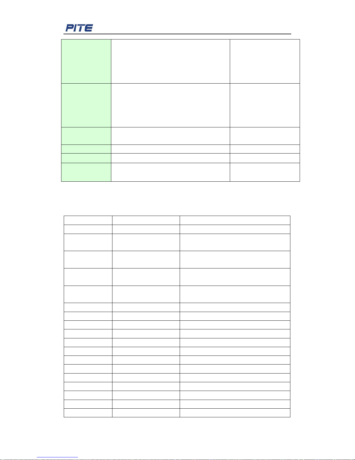
2.5 Definition of Abbreviation
Here is definition of all abbrev iated words in PITE 3561main body menu:
Abbreviation
Full name
Where are they?
AVG
average
VOLTS/AMPS/HERTZ
Amp(s) Current
VOLTS/AMPS/HERTZ,
HARMONICS,etc.
VECT. Vector graphic
VOLTS/AMPS/HERTZ,
HARMONICS,etc.
DET. Detailed
VOLTS/AMPS/HERTZ,
HARMONICS,etc.
TRE. Trend
VOLTS/AMPS/HERTZ,
HARMONICS,etc.
HIST.
Histogram
HARMONICS
HAR.
harmonic
HARMONICS
PF
power factor
POWER & ENERGY
Ne.s. Neg at ive sequence UNBALANCE
Po.s. Positive sequence UNBALANCE
Unbal. Unbalance UNBALANCE
Rec. record RECORD
V Voltage RECORD
Fluct.
Fluctuation
FLICKER
Pst
Short-term Flicker
FLICKER
Plt
Long-term Flicker
FLICKER
Thrs
threshold
DIPS/SWELLS
T
time
INRUSH
Page 9
PITE 3561 Power Quality Analyzer
9
CH channel SCOPE
DEL. delete SYSTEM-DATA MANAGEMENT
TO USB Save in USB drive SYSTEM-DATA MANAGEMENT
CALI. calibration SYSTEM-SETTINGS
I
Current
SYSTEM-SETTINGS
PARA
parameter
SYSTEM-SETTINGS
PARAM
parameter
SYSTEM-SETTINGS
TP
touch panel
SYSTEM-SETTINGS
Rng
range
SYSTEM-SETTINGS
PT potential t r ansformer SYSTEM-SETTINGS
CT current transformer SYSTEM-SETTINGS
3. MEASUREMENT PREPARATION
3.1 Battery Charging
Before measurement, make sure that the main unit has sufficient power. When the battery
power gets low, please charge it timely.
PITE 3561 AC power adaptor which could be connected withmain body for proper AC
power supply. This is used when the Analyzer is working in the function of “Recording”
which may take longer t i m e online.
WARNING: To avoid electric shock, please always connect the battery charger/power
adapter to the AC outlet befor e connecting it to the Analyzer.
3.2 Cable Connection
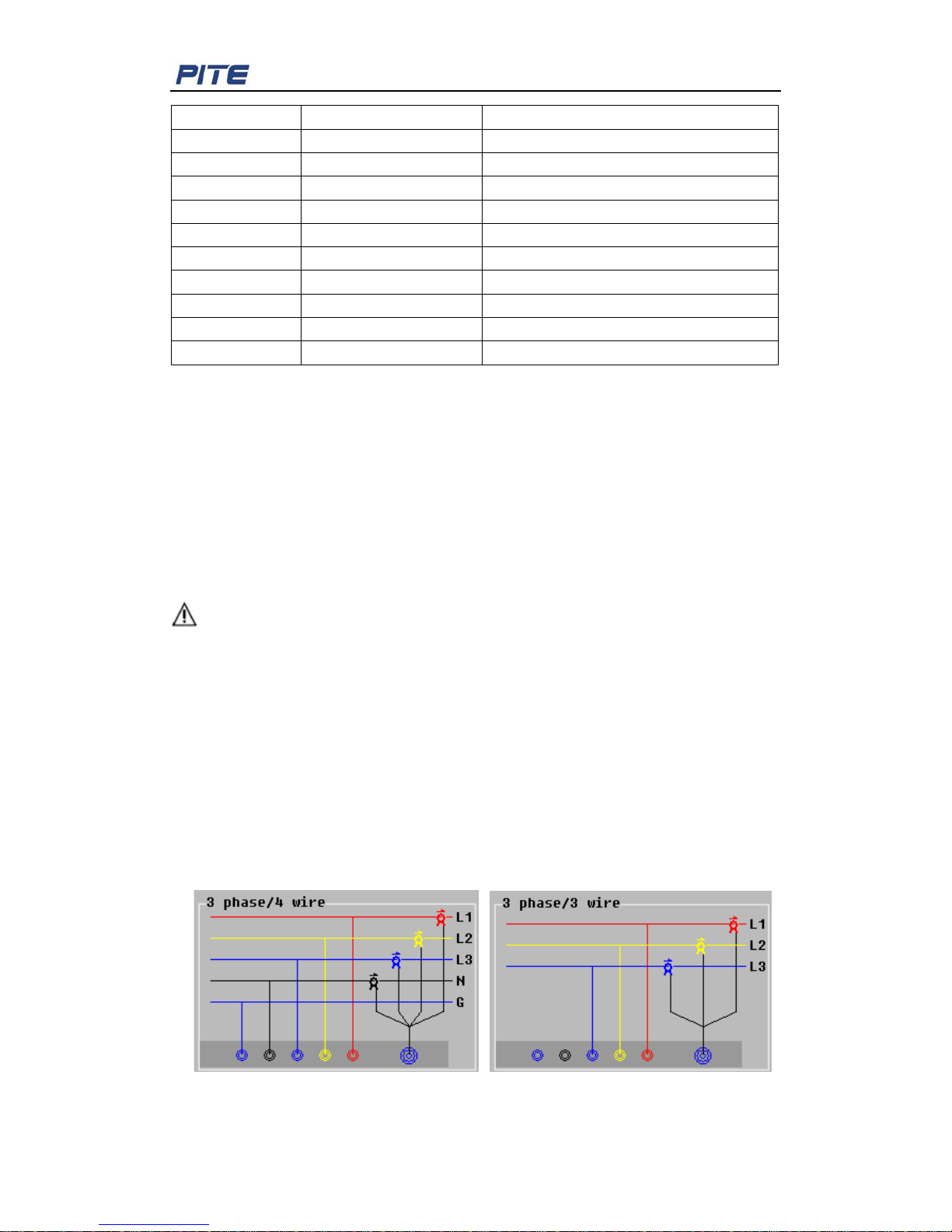
Before measurement, please connect the voltage testing leads with analyzer. Then select
necessary v oltage test probes and current clamps. M ake sure th at the probes, clamp s and
measured conducting wires are correctly connected like instruction below (Fig. 3.2.1 and
Fig. 3.2.2). Try to get the tested leads vertically pass through the clamp hole s as bel ow.
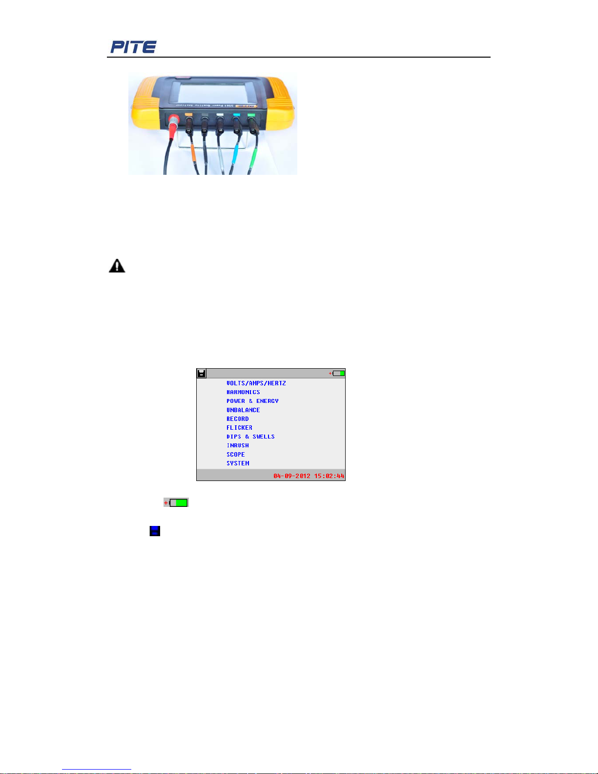
Colors of volt age testing sockets for L1, L2, L3 and Neutral and Ground will be all in blac k
with color labels nearby for different countries standards. Voltage testing leads are all
labeled in colors accordingly at both ends of the lead. Please connect the leads correctly
(e.g. Fig. 3.2.3).
Fig. 3.2.1 Fig. 3.2.2
Page 10
PITE 3561 Power Quality Analyzer
10
Fig. 3.2.3
PITE 3561 only have connections for 3 phase/3 wire and 3 phase/4 wire. Before the
measurement, please firstly do system setting. For detailed instruction, please refer to
5.2.2 Parameter Setting. If you need to test single phase, please select 3 phase/4 wire
and connect voltage an d current signal to relevant position o f L1.
DANGER: To avoid electric shock and sh ort-circuit, please carefully connect the
testing probes with the testing sources.
3.3 Analyzer Power-on
Press the red power button on main unit to turn on t he analyzer. Screen of main menu will
be displayed as below upon power-on.
Fig. 3.3
Battery icon
on the right top indicates the power status of battery. If it is low, please
charge it timely.
The icon
on the left top is for screenshot. To save the current screen, please firstly
connect the USB drive. To avoid mis-operation, please click the icon to highlight it and
press again for screenshot.
“04-09-2012 15:02:44”: This is the system time. For ti me and its format setting, please
refer to 5.2.3 Date & Time.
NOTE: The screen will automatically bec o me dark for pow er s aving when it is idle for 1
minute. To restart it, please click anywhere on the screen.
4. MEASUREMENT
In this detailed description for P ITE 3561 measurement functions, three phase color will
be exemplified as L1(Red), L2(Yell ow), L3(Blue) and Neutral (Black). The color code will
Page 11
PITE 3561 Power Quality Analyzer
11
be different depending different countries or districts. For detailed color setting, please
refer to 5.4 Voltage Color Setting.
4.1 Volts/ Amps/ Hertz
It measures fundamental par ameters including voltage, current and frequency for all
phases and Neutral. Detai led i nf ormation is displayed with trending and waveform.
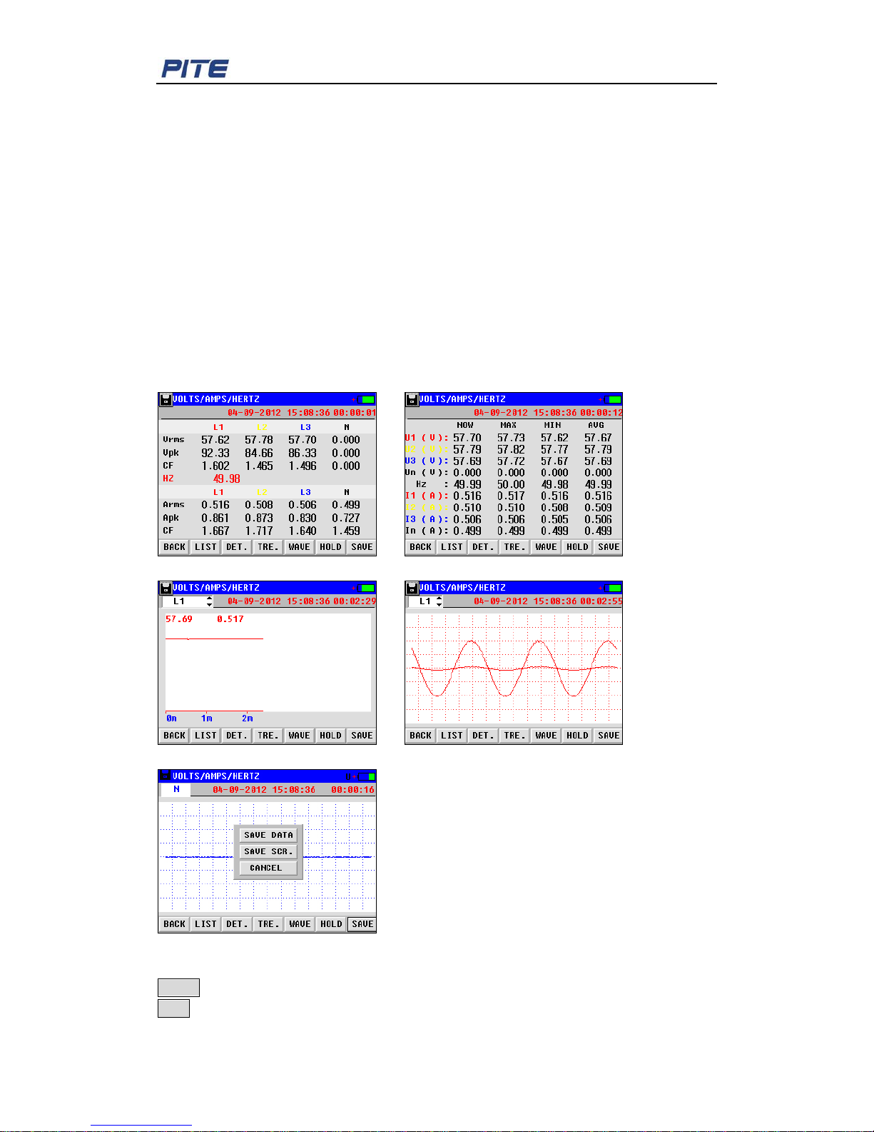
To start testing, click “VOLTS/AMPS/HERTZ” on the main menu. A nd y ou will c ome to t he
following screen. It presents 3-phase voltage, 3-phase current, Neutral current and L1
freqeuncy as below.
For voltage, it is value for phas e-neutral in 3 phase 4 wire. And in 3 phase 3 wire, it is
value for phase-phase.
Fig. 4.1.1 List Fig. 4.1.2 Detail
Fig. 4.1.3 Trend Fig. 4.1.4 Wave
Fig. 4.1.5 Save
Descriptions of the buttons on the screen are as below:
BACK: Click it to go back to the upper menu.
LIST: Listing for Voltage (rms, peak value and crest factor), current (rms, peak value and
Page 12
PITE 3561 Power Quality Analyzer
12
crest factor) and frequenc y (Fig. 4.1.1).
DET.: It presents detailed testing data for 3 phase and N including present, maximum,
minimum and average data (Fig. 4.1.2).
TRE.: It displays the trending for voltage, current and frequency for each phase. Click the
left top box to change the display i ng data.
WAVE: It shows the waveform of each phase for voltage and c ur r ent (Fig. 4.1.4).
HOLD: Click this button to read the measurement results and save them. To restart, click
the other buttons, like LIST.
SAVE: Click to save the testing data or current screen. For screenshot, the USB drive
should be connected (Fig. 4. 1. 5).
“04-09-2012 15:08:36”: It indicates the present ti me.
“00:00:16” indicates the dur at ion of this measurement.
NOTE: Manually saving of testing data is i mport ant for all measurements exce pt “Record”
function which will automatically save the data.
4.2 Harmonics
Harmonics can be a huge hazard in electrical system, especially old ones. Test of
harmonics is very important. This device tests THD and harmonic voltage and harmonic
current for all phases with trend and spectrum (histogram). For comparison of testing
value with international standar ds like EN 50160, pl ease refer t o 7. PITE 3 5 61 DATAVIEW
SOFTWARE.
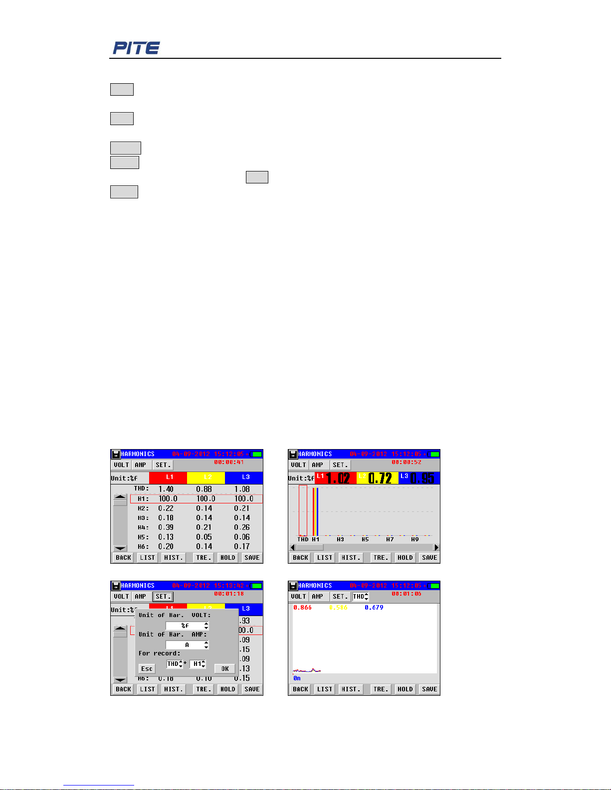
To get started in screen, click “HARMONICS” in mai n menu. Wait for 10 seconds. You will
come to the list of testing data in Fig.4.2.1.
It measures harmonic v olt age and current for all phases.
Fig.4.2.1 List Fig.4.2.2 Histogram
Fig.4.2.3 Setting Fig.4.2.4 Trend
Page 13
PITE 3561 Power Quality Analyzer
13
Below are the detailed descripti ons of all the functions in Harmonic measurement:
Function keys of Back, LIST, HIST, HOLD and SAVE have the same operation as
described in 4.1 Volts/ Amps/ Hertz.
SET.: It is setting for displaying units of voltage and current like Fig.4.2.3. When you click
the button VOLT or AMP, you will see the presetting unit. Under “For record”, you could
select any two harmonics that will display in TRE. (Selectable in Fig.4.2.4).
TRE.: It presents the trending for measuring data. Click the top center; you could switch
between the two presett in g harmonics (Fig.4.2.4).
4.3 Power & Energy
This is for testing both Pow er and Energy. They include the functions as be lo w:
Power: 3-phase apparent power (kVA), ac tive pow er ( kW), reactive pow er (kV AR), pow er
factor (PF), voltage (V), current (A) and phase angle.
Energy: 3-phase apparent energy (kVA), activ e energy (kW), reactive energy (kVAR),
power factor, kVAh, kWh and kVARh.
In energy testing, the analyzer measures power consumpti on by integrated power
measurement over time. Y ou could use this function for quick verificat ion of revenue
meters.
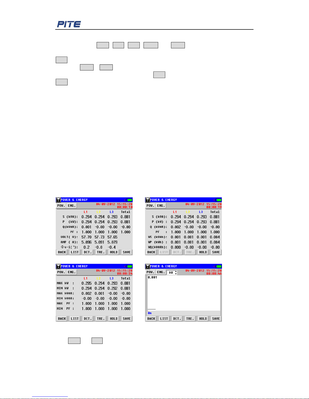
To get started, click “POWER & ENERGY” in main menu and wait for 5 seconds, you will
come to the screen below:
Fig.4.3.1 List Fig.4.3.2 Energy
Fig.4.3.3 Detail (Power) Fig.4.3.4 Trend
Click POW and ENG on the left top to switch between power testing and energy testing.
Operations of all the buttons ar e s ame as described before.
In Power testing, you could view the trending of act ive power (kW) and power factor (PF)
Page 14
PITE 3561 Power Quality Analyzer
14
by Clicking the button TRE.. These two items could be switched to each other in the
option box on the top (Fig.4.3.4).
4.4 Unbalance
Unbalance is expressed as the ratio of negative sequence and null sequence to positive
sequence components. A perfect balanced system has no negative sequence or null
sequence component s .
Before testing measurement of unbalance, you could alternatively set initial angle and
angle range of different way. For inst ruc t i on, please refer to 5.5 Phase Angle Setting.
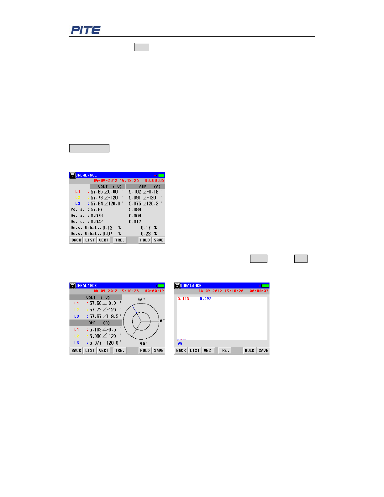
Unbalance measurement will test 3-phase unbalance for both voltage and current. Click
UNBALANCE in the main menu and wa it for 5 seconds to start testing as Fig 4.4. 1.
It presents the 3-phase unbalance in negative sequence (“Ne.s.”), positive sequence
(“Po.s.”) and zero sequence (“Nu.s.”).
Fig 4.4.1
The data could also be v iew ed in vect or when y ou click th e butt on VECT and click TRE to
view the tendency of measurement data. I t will trac k the changes o f unbalanc e as dif ferent
loads come on and of f line.
Fig. 4.4.2 Vector Fig. 4.4.3 Trending
4.5 Record
In the function “RECORD”, PITE 3561 will become a monitor for the testing functions of
Volt age/c urrent/fre quency, Power, Harm onics, Unbalance and Flic ker simultaneously. This
function will help you uncover some hard-to-find or intermittent issues by recording all the
testing data. Maximally PITE 3561 can r ecord up t o 960 hours wit h interv al of more than 2
minutes and 59 seconds. It will capture shorter time duration with recording inter val as low
as 3 second.
Page 15
PITE 3561 Power Quality Analyzer
15
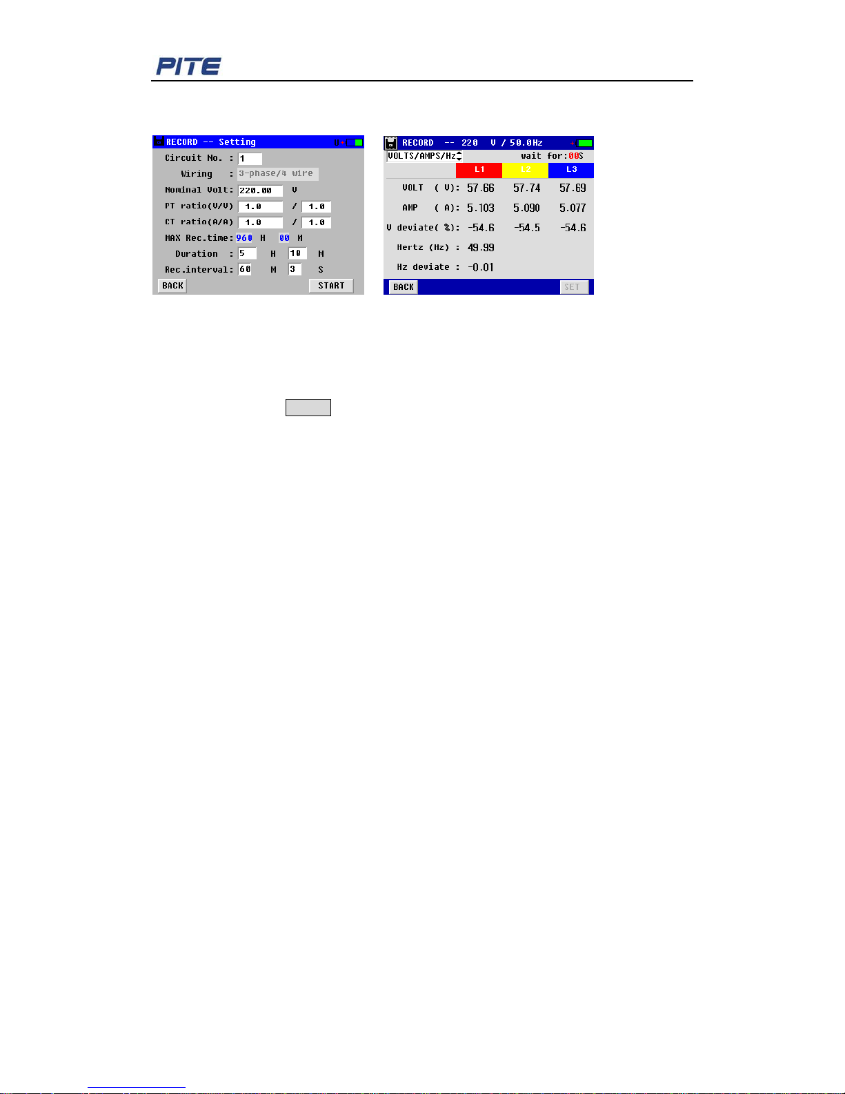
Click ”RECORD” in the main menu you wi l l come to the next screen for parameter setting
as below:
Fig. 4.5.1 Fig. 4.5.2
Firstly do all the parameter settings. To change the way of wiring, please refer to 5.2.2
Parameter Setting. As recording interval changes, maximum recording time will
automatically be calculated.
After the setting, click START to proceed with recording measurement. The testing record
will be automatically saved in m ain unit memory. To vie w this information, please refer to
5.1 Data Management. Screen will display live data simultaneously for all functions. Click
on the left top box to shift to other events like harmonics, flic ker a nd s o on.
NOTE: To ensure sufficient power supply during data recording, you are suggested to
connect the Analyzer with proper AC source with power adaptor.
4.6 Fluctuation/ Flick er
Flicker measurement gives an indication of whether voltage fluctuations will cause
annoyance for a typical person working under incandescent lighting (60W). A reading
higher than 1 means most people will perceive the voltage changes. The testing is
optimized on a incandescent lighting powered by 120V/50Hz or 230V/60Hz. Short-term
flicker (Pst) and long-term flicker (Plt) for each phase will be displayed.
Voltage fluctuation is defined as a seri es of high-speed variation or continuous change of
voltage rms. variation cycle is more than power frequency cy cle. In pow er sy stem, volt age
fluctuation could happen many times. Variation process could be regular or irregular.
Voltage fluctuation is normally described as relative voltage fluctuation. It is numbered as
the ratio of two nearby extremums (keep changing in series of voltage rms) difference to
rated voltage.
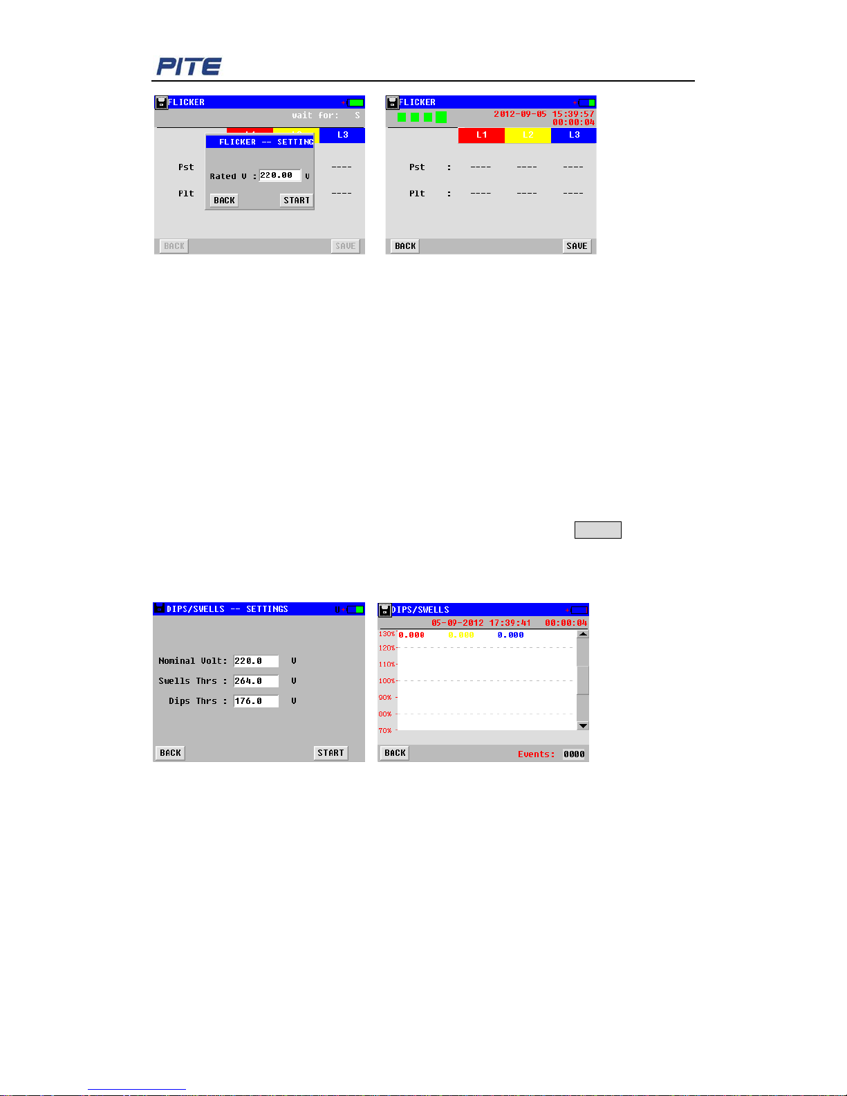
Click “FLICKER“in the main menu, input the rated voltage an d wait for 6 secon ds, you w ill
see the screen as below (Fig. 4. 6. 2) . If there is any event, it will be displayed on the
screen.
Page 16
PITE 3561 Power Quality Analyzer
16
Fig. 4.6.1 Fig. 4.6.2
4.7 Dips/ Swells
Dips & Swells are used to recor d t r ansient changes of voltage as short as h al f a c ycle.
When the rms voltage exceeds the nominal voltage by 10 to 80% for 0.5 cycle to 1 minute,
the event is called a "swell".
A "dip" (in British English) or a ”sag" (in American English - the two terms are equivalent)
is the opposite situation: the rms voltage is below the nominal voltag e by 10 to 90% for 0. 5
cycle to 1 minute.
Dips & Swells mode makes rapid rms voltage and current r eadings on all phases.
To begin the test, clic k “Dips & Swells” for parameter settings.
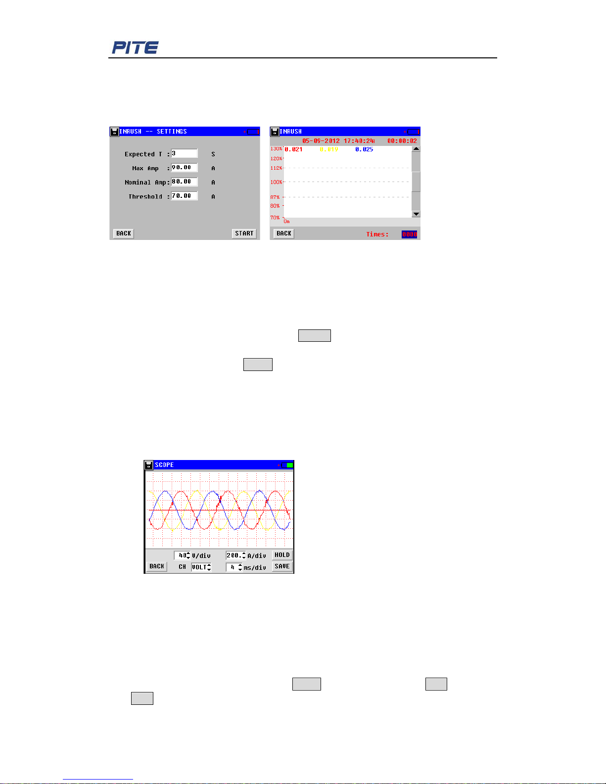
Input the nominal voltage, s well t hresho ld and d ip thr esho ld, an d clic k START to carry out
the test. You will see the waveform in Fig 4.7.2. In this screen, nominal voltage is defined
as 100%. For example, if no minal voltage is 220V, then 264V will be descr ibed as 20%
upper. 176V will be described as 20% lower.
Fig 4.7.1 Fig 4.7.2
4.8 Inrush
Inrush is the dash current happens w hen there is high load or low impedance load.
Generally, when the load is in normal working condition, current will be stabilized after
some time, like the duration after so m e bi g loads (e.g. motor and frequency converter)
starts.
Inrush testing function could record the variation trend from dash curre nt to current
stabilization. This process is called one inrush.
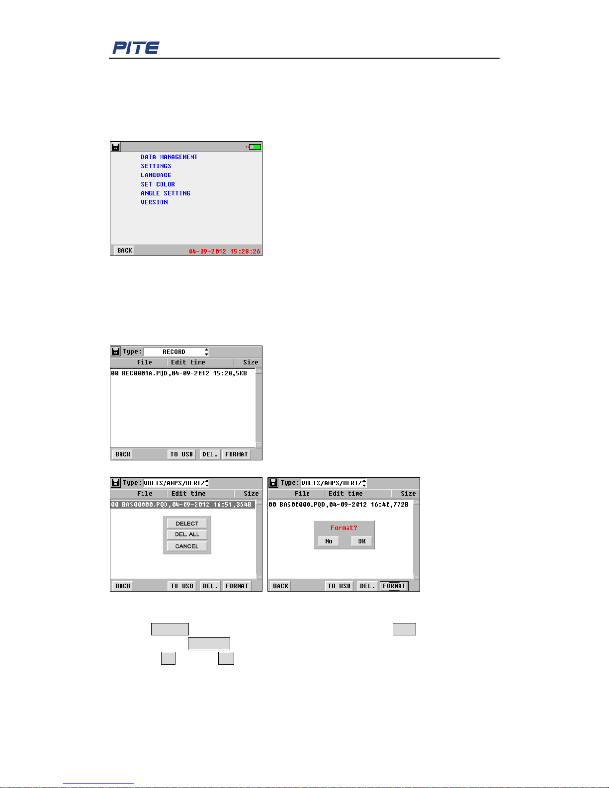
Click “INRUSH” in main menu, you will come to the screen for par ameter setting as Fig
4.8.1.
Page 17
PITE 3561 Power Quality Analyzer
17
“Expected T” indicates th e expected time for testing inrush.
“Max Amp” indicates the maximal cur r ent t hat expected inrush may reach.
“Nominal Amp” indicates the curr ent value of device under normal working c ondition.
“Threshold”: it is call ed one inrush when current value reaches t he pr esetting threshold.
Fig 4.8.1 Fig 4.8.2
Nominal current is used as standard (100%), if current v alue reaches thresh old, it is called
one event. If nominal current is 20A, threshold is set as 30A. 30A is at 150% .
“Max Amp” is the maximal c urr ent that can be displayed during testing of inr ush.
For exact time when inrush happ ens , users can refer to PC software of PITE 3561.
After the parameter sett in g, click the button START to begin the test Fig 4.8.2.
PITE 3561 will automatically keep record when inrush is detected. To manually quit the
testing, please click the but ton BACK.
4.9 Scope
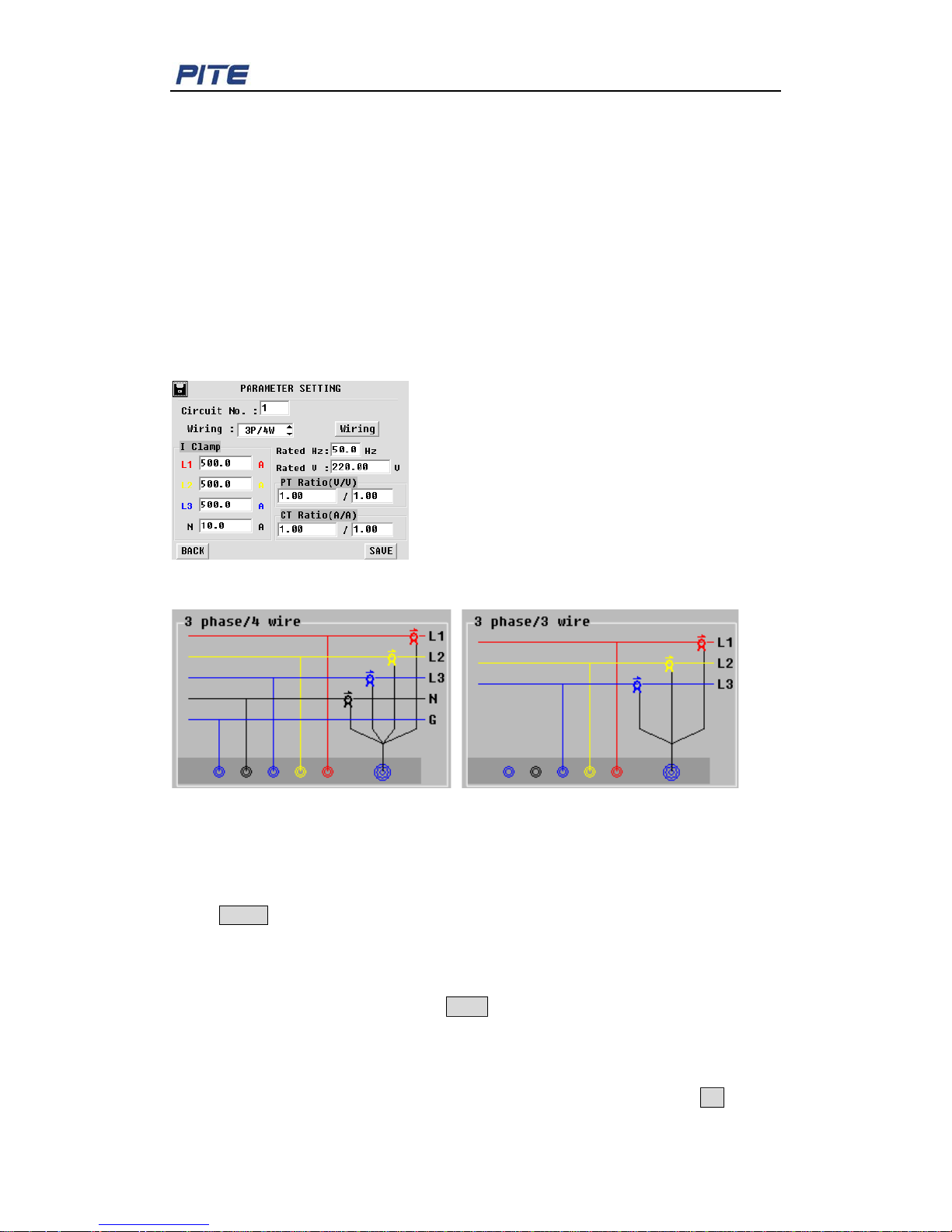
Oscilloscope function in PITE 3561 could simultaneously testing 3 phase 4 wire power
system for voltage and current. It is used to observe and capture signal variation when
power system is running. Click “SCOPE” in main menu, you will see the screen as Fig
4.9.1.
Fig 4.9.1
For the setting of displayed par ameter, please click the options at t he bottom of the scr een
to view the scope in dif ferent way.
“CH” indicates channe l. It has options including voltage, current, L1, L2, L3 and N.
“div” indicates each lattice where the scope is described. Voltage has the range from
20V/div to 300V/div. Current has the range fr om 0.25 A to 2.5 A. time ranges from 1ms/div
to 80ms/div.
To quit the scope testing, press t he butt on HOLD and it will be change to RUN. T o restart,
click RUN.
Page 18
PITE 3561 Power Quality Analyzer
18
5. SYSTEM MANAGEMENT
System setting includes function for data management, parameter setting, calibration,
time setting and so on. For full information and operation, please click “SYSTEM” on main
menu.
Fig 5
5.1 Data Management
All testing data you have saved bef or e c ould be viewed, transferred to PC or deleted
directly in data management . Screen with detailed information will be displayed as below
by going to “SYSTEM””DATA MANAGEMENT”.
Fig 5.1
Fig 5.1.1 Fig 5.1.2
To save the data in your PC for analyzing, insert the USB drive properly, select the data
and click TO USB. To delete the data, select the target and clic k DEL.. To format all
testing data, click FORMAT directly. Warning screens will pop up as Fig 5.1.1 and Fig
5.1.2. Click No to exit or OK to confirm the operation. Please note that you have saved
the data properly. Once delet ed or formatted, they could not be recovered.
Page 19
PITE 3561 Power Quality Analyzer
19
5.2 System Setting
5.2.1 Calibration
This is for calibrating the parameter of PITE 3561. All data have been well calibrated in
PITE factory before the product is sent our customers. For testing accuracy, you are not
suggested to carry out this operation if unnecessary. If you really need it, please contact
your supplier or PITE for separate instruction.
5.2.2 Parameter Setting
Parameter setting is required before your testing, mainly described in 4.
MEASUREMENT.
Please go to “PARAM SETTING” under menu “SETTINGS”. Screen will be as below :
Fig. 5.2.2.1
Fig. 5.2.2.2 Fig. 5.2.2.3
“Circuit No.” indicates the serial number of circuit. This number is self-defined. You will
view this number after y ou have saved the testing data and transfer to PC.
“Wiring” has two ways, 3 phase/4 wire and 3 phase/3 wire. Select either way and click the
button Wiring to view connecting instruct ion as Fig. 5.2.2.2 and Fig. 5.2.2.3.
“I clamp” means current clamp. It is unique and c ustomized for each configuration.
Other parameters like rated Hz and Rated voltage should be input accordingly based on
concrete situation.
After all settings, please click the button SAVE and it will automatically go to upper menu.
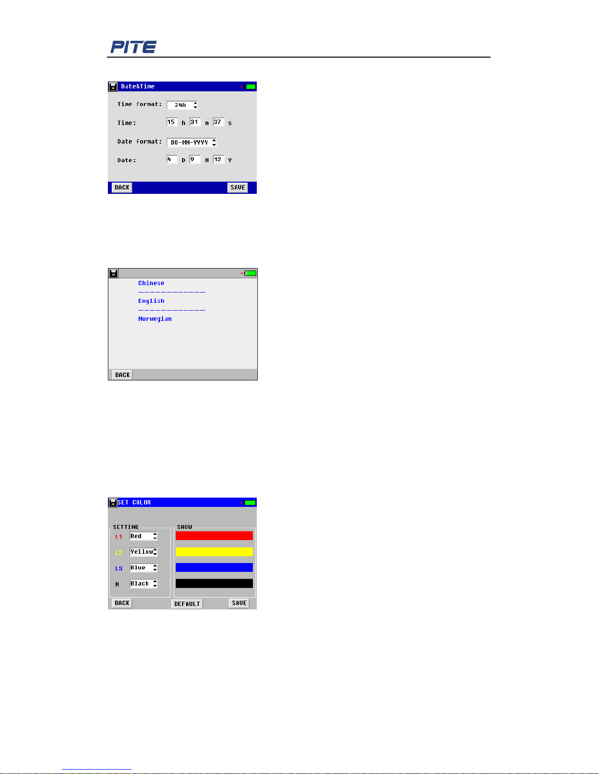
5.2.3 Date & Time
For system time setting, please follow the route “SYSTEM”“SETTINGS”“DATA &
TIME”. Click each option for date, time and format setting. After setting, click OK to save
Page 20
PITE 3561 Power Quality Analyzer
20
the change.
Fig. 5.2.3
5.3 Language Setting
Click “LANGUAGE” under the menu “SYSTEM” and select the language needed in the
following screen:
Fig. 5.3
5.4 Voltage Color Setting
For standards of three phase voltage color code in different countries, PITE provide
customized setting to b e in accor dance wit h the volt age tes ting le ad. For it s se tting, pl ease
go to “SET COLOR” under t he menu “SY S TEM ”, you will see the screen below for setting
color of L1, L2, L3 and Neutral.
Fig. 5.4
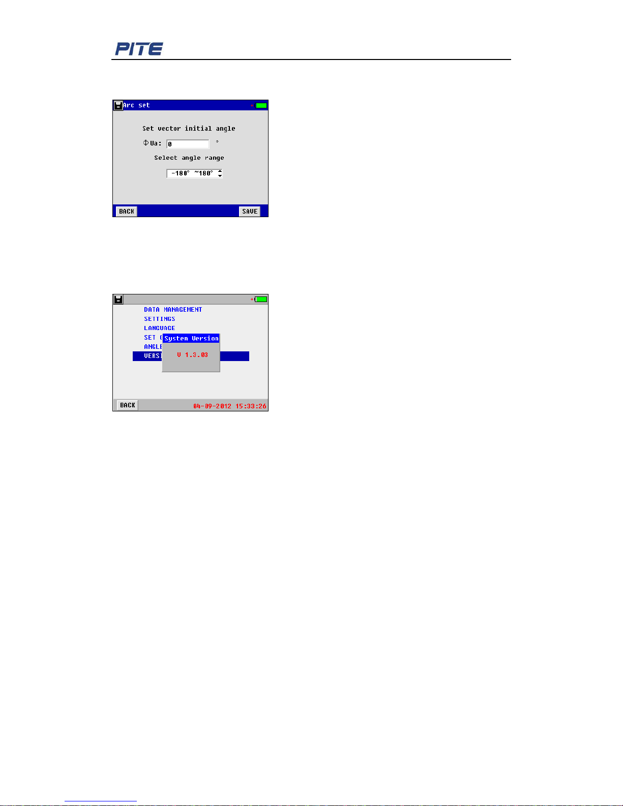
5.5 Phase Angle Setting
This will enable you to set different way of display for phase angle in three phase
unbalance. Please go to “ANGLE SETTING” under menu “SYSTEM”. You will see the
Page 21
PITE 3561 Power Quality Analyzer
21
screen as below for initial angle setting and angle range (optional for -180 o -180 o and
0~360
o
).
Fig. 5.5
5.6 Firmware Version and Update
Click “VERSION” under m enu “SYSTEM”, you will see the firmware v er sion.
Firmware Update:
PITE constantly updates its program as per customers’ need. To update the unit, please
follow the steps as below :
1) Copy the two files (named “Program.hex” and “SCRIPT00.txt”) from PITE to the root
directory of PITE USB driv e.
2) Connect the USB drive wit h PI TE 3561 main body and restart the unit.
3) Firmware update will be done i n ar ound one minute.
6. SERVICE AND MAINTENANCE
6.1 Maintenance
1). Cleaning
Clean PITE 3561 main unit and its accessories (current clamps, voltage probes, etc.) with
a damp cloth and a mild soap. Do not use abrasives, solvents, or alcohol, as they can
deform or discolor the analyzer and the accessories.
2). Storage
Place the PITE 3561 and all its accessories into the case after u si ng . It is unnecessary to
remove the battery pac k even storing it for a long time. However , t he battery will dischar ge
itself gradually overtime. So please charge the bat teries per iodically (like once a month) to
Page 22
PITE 3561 Power Quality Analyzer
22
keep them in optimal cond ition.
3). Battery Maintenance
3.1). Charging the Batteries
Connect the battery charger to the power supply then to PITE 3561 main unit. After the
battery is full charged, it will automatically enter overcharge protection. No damage will
occur to the analyzer ev en if you char ge the batteries overtime.
3.2). Extending the Battery Life
To obtain opti mized per for mance of th e batt ery, discharge the battery completely and the n
recharge it fully.
6.2 FAQ
Below are the frequent asked questions that you might come across when using PITE
3561:
Q: The PITE 3561 can not start up. What is goin g wro n g?
A: The batteries may be power off. If so, charge it properly.
Q: The Analyzer keeps beeping when it’s on.
A: Power of battery is low. Charge it for a while and try again.
Q: The Analyzer is power off suddenly duri ng t esting.
A1: The battery may be out of condition. Replace it with a new one and tr y again.
A2: The testing leads may be well connected. Unplug the testing leads and plug again.
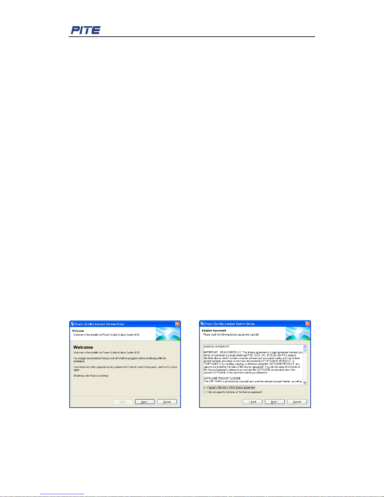
7. PITE 3561 DATAVIEW SOFTWARE
7.1 Software Ins t allation
Double-click the software name like “PowerQualityAnalysisSystem v5.31 Setup.exe” in
the PITE USB drive to start installation of the software. Click “Next”select ”I agree to the
terms of this license agreement” Click “Next”Change installation path if
necessaryClick “Finish” to complete the software i nstallation. Below screenshots are for
your reference:
Page 23
PITE 3561 Power Quality Analyzer
23
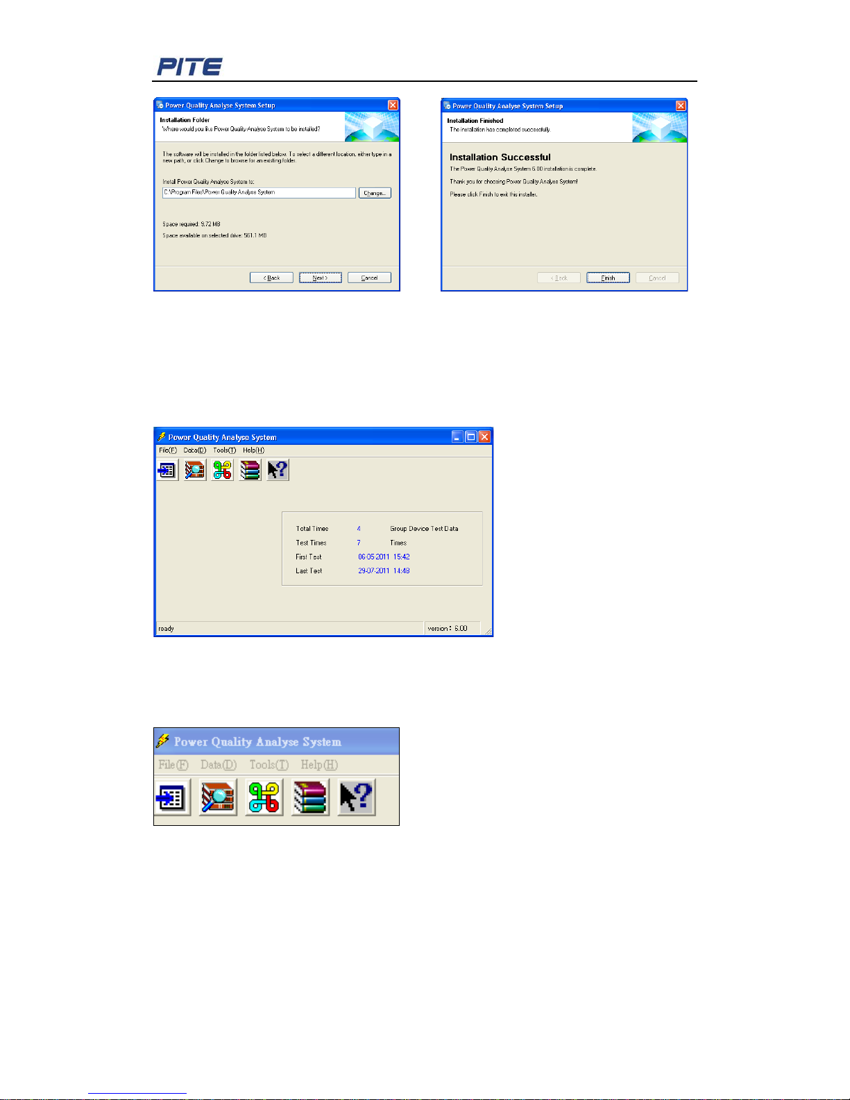
Fig 7.1.1
7.2 Software Operation
After installation is finished, click the icon named “Power Quality Analyse System” on
computer desktop to run the software. You will see the main screen as below:
Fig. 7.2.1
It has 5 shortcut icons one the menu, when you move the mouse icon on each of them,
their functions will display as: Import data, View data, Circuit info, Zip database, Version
info. You could also refer to the menu directly.
Fig. 7.2.2
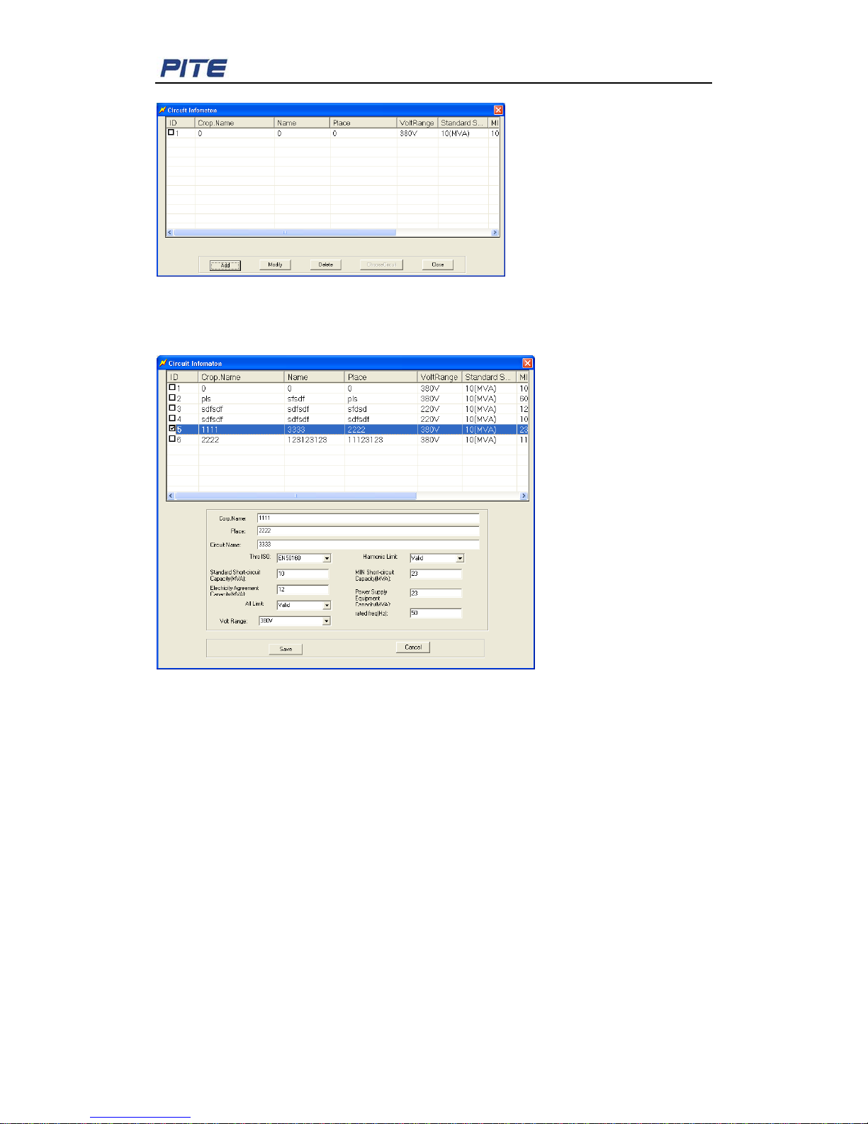
Input circuit information
This is to build up a database for all testing data that will be distinguished in different
groups based on company name, size name and so on.
To do this, please go to the menu “File” and then “Input circuit info”, you will see the
screen as below:
Page 24
PITE 3561 Power Quality Analyzer
24
Fig. 7.2.3
Go to menu “File”—“Input circuit info”—select ID number—Click “Modify”, you will see the
different setting for standards in the screen below:
Fig. 7.2.4
“Thrs ISO” means threshold standard for different countries for comparison of harmonics.
It could be EN 50160, Chinese standard or user defined standard. Then these value limits
will be selected as “Valid” and information like “Standard short-circuit capacity” will be
compared with testing result of harmonics to judge if the testing result has any problem in
the local standard.
If this standard or limit is meaningless to you, you just set is “Invalid” in “Harmonic limit”
and “All Limit”.
To add circuit information, please click the button “Add” in Fig. 7.2.3. Other operation is
same as above.
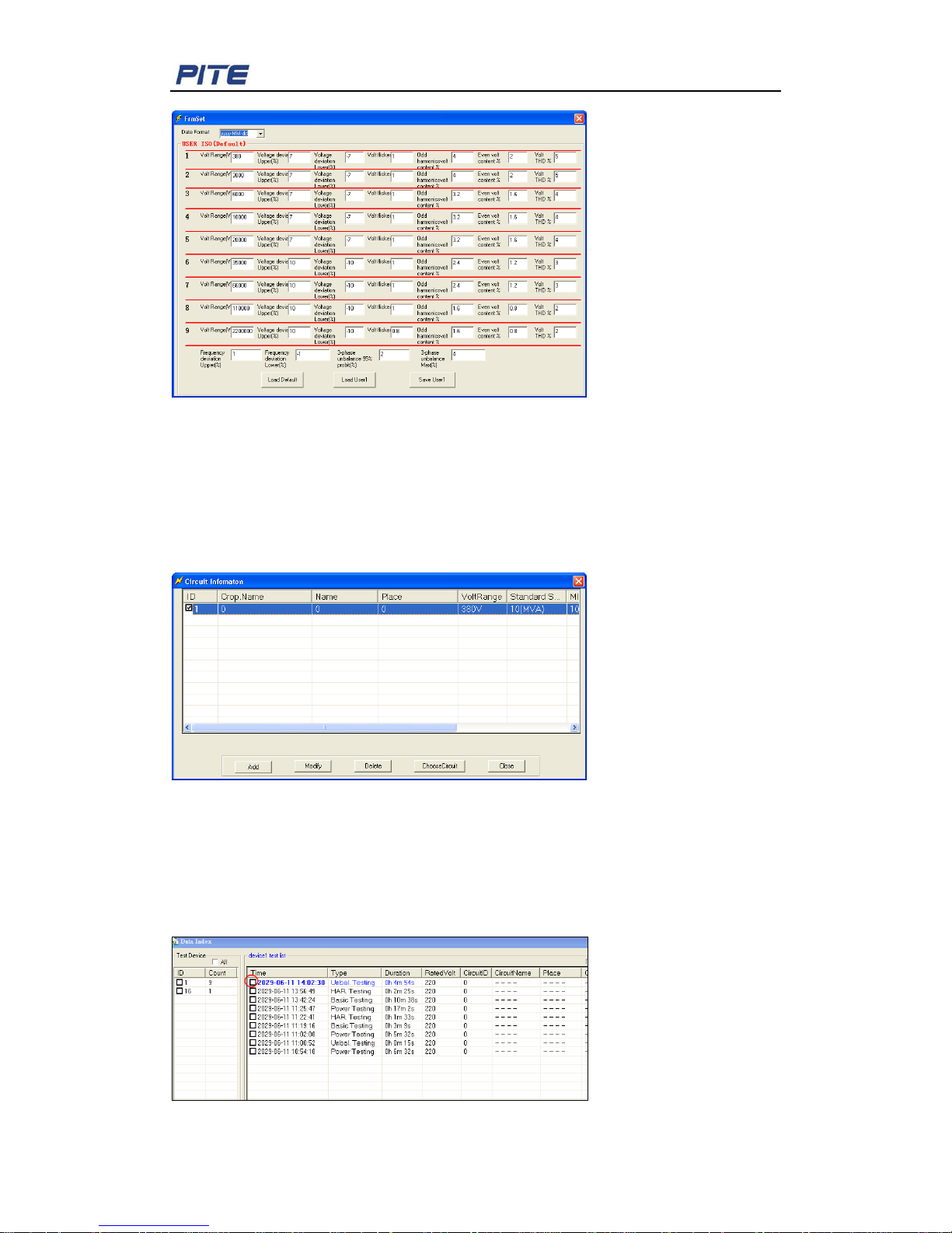
User-defined vol tage range
If above voltage range does not meet your local requirement, you could set this
information by yourself. Please go to menu “Tools””System set”. You will come to the
screen as below:
Page 25
PITE 3561 Power Quality Analyzer
25
Fig. 7.2.5
You could set the voltage ranges and their relevant standards. After the setting, please
click the button “Save user 1”. Then you will have user defined data and default data.
Import testing data:
To import data, please go to menu “File””Import data”Click “Yes”select ID number
as below and click “ChooseCircuit”Select the testing data t o i m por t .
Fig. 7.2.6
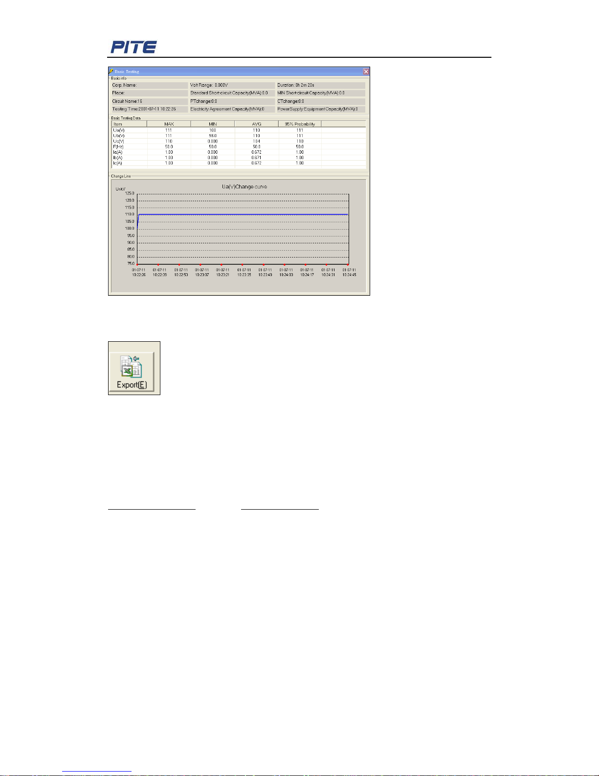
View All Testing Data
To view data, please choose “Data”---“All data”, and t hen you will get a chart as below.
You could also select data based on relevant testing function (e.g. Harmonics) under
“Data” to view them individually. Double click relevant testing record; you will see detailed
testing data exempli fied as below.
Page 26
PITE 3561 Power Quality Analyzer
26
Fig. 7.2.7
To export the testing data to a report in Excel format, please choose the button ”Export”
like below (Fig. 7.2.8) and t est ing r eport will be exported in the format of Micros oft Excel.
Fig. 7.2.8
8. ORDER INFORMATION
PITE TECH. INC.
4/F , Bldg A, Chiwan Industrial Park, Shaodi Rd., Chiwan, Shekou Ar ea, Shenzhen, China.
TEL: +86-755-2680 5759 FAX: +86-755-2688 0310
[email protected] www.pitetech.com
 Loading...