

Page 1

PITE 3551T Power Meter Tester
User Manual
P-130902-V1.2
4/F, Bldg A, Chiwan Industrial Park, Shaodi Rd.,
Chiwan, Shekou Area, Shenzhen, China.
TEL: +86-755-2680 5759
FAX: +86-755-2688 031 0
www.pitetech.com
Page 2

PITE 3551T User Manual
1
Catalogue
1. INTRODUCTION ..................................................................................................................... 3
1.1 Accessories .................................................................................................................... 3
1.2 Safety Information .......................................................................................................... 4
1.3 Operating Precautions ................................................................................................... 5
2. ABOUT PITE 3551T ................................................................................................................ 5
2.1 Applications .................................................................................................................... 6
2.2 Features ......................................................................................................................... 6
2.3 Functions ........................................................................................................................ 6
2.4 Technical Parameter ...................................................................................................... 6
3. MEASUREMENT INSTRUCTION .......................................................................................... 7
3.1 Measurement Preparation.............................................................................................. 7
3.1.1 Instrument Panel .................................................................................................. 7
3.1.2 Cable Connection ................................................................................................ 8
3.1.3 Instrument Menu ................................................................................................. 11
3.1.4 Battery Charging ................................................................................................ 12
3.2 Measure Different M eters............................................................................................. 12
3.2.1 Three Phase Met er i ng Unit ................................................................................ 12
3.2.2 Three Phase Kwh Meter .................................................................................... 14
3.2.3 Single Phase Meteri ng Un it ............................................................................... 15
3.2.4 Single Phase Kwh Meter ................................................................................... 16
3.2.5 High-volt Kwh Meter .......................................................................................... 16
3.3 Meter Online Monitor .................................................................................................... 18
3.3.1 Low-volt Metering Unit ....................................................................................... 18
3.3.2 Low-volt Kwh Meter ........................................................................................... 19
3.3.3 High-volt Kwh Meter .......................................................................................... 20
3.4 Judgment for Wire Connect i on .................................................................................... 21
3.5 Measure Primary Loa d ................................................................................................. 22
3.6 Test CT Ratio ................................................................................................................ 22
4. SYSTEM MANAGEMENT .................................................................................................... 23
4.1 Data Management ........................................................................................................ 23
4.2 System Setting ............................................................................................................. 24
4.2.1 Parameter Calibrati on ........................................................................................ 24
4.2.2 Parameter Setting .............................................................................................. 24
4.2.3 Date & Time Setting ........................................................................................... 25
4.2.4 Phase Angle Setting .......................................................................................... 25
4.3 Language Selection ..................................................................................................... 26
4.4 Firmware Ver sion and Upd ate ..................................................................................... 26
4.5 Voltage Color Setting ................................................................................................... 26
5. SERVICE A ND MAINTENA NCE .......................................................................................... 27
5.1 Maintenance ................................................................................................................. 27
5.2 FAQ .............................................................................................................................. 27
6. PITE 3551T DATA MANAGEMENT ..................................................................................... 28
Page 3

PITE 3551T User Manual
2
6.1 Software Installation ..................................................................................................... 28
6.2 Software Operat ion ...................................................................................................... 28
7. ORDER INFORMATION ....................................................................................................... 30
Page 4
PITE 3551T User Manual
3
1. INTRODUCTION
This Users Manual gives full infor mati on on how to use PITE 3551T Three Phase Power Meter
Tester (hereinafter called “Tester”) safely and effectively. Please read the manual carefully so
as to obtain maximum perfor ma nc e of the monitor and its accessories.
Important: Read this manual completely before connecting and pow ering on the t ester to av oid
possible damage caused by improper use of this instrument.
1.1 Accessories
After receiving the PITE 3551T unit, please ensure that no damage occurred during
transportation. Upon any damage or failure of operation based on this instrument, please
contact your supplier i m m edi at ely. And make sure you have each ite ms b elow:
Main unit (1)
Current Clamp (3) *
Voltage Testing Lead (4)
Voltage Clips (4, w ithout cover on the top)
Alligator Clips (4, with cover on the top) *
Voltage probe pin (4)
Scanning head (1)
Calibration lead (1) *
Pulse input lead (1)
User manual (1)
Power adaptor (1)
Quick power supply lead (1)
USB drive (1)
USB converter (1)
Thermal printer (1, Optional)
*NOTE:
1) Current clamp is customer-tailored for different range, below picture is just for reference.
2) Alligator clips are for connecti on w it h pulse input lead or calibration lead.
3) Calibration lead is used when standard meter with higher accuracy classes is used to test
PITE 3551T.
Reference pictures:
PITE 3551T main unit
Current clamp
Voltage testing leads
Page 5
PITE 3551T User Manual
4
Voltage Clips
Alligator Clips
Voltage probe pin
Scanning head
Calibration lead
Pulse input lead
User manual
Power adaptor
Quick power supply lead
USB drive
USB converter
Thermal printer(Optional)
1.2 Safety Information
For your protection, pleas e r ead t his safety information completely before ope r at ing the
activator. Carefully observe all warnings, precautio ns and instructions.
WARNING: Servicing described in t his manu al is t o be don e only by qual ified per sonne l. T o
avoid electrical shock, do not ser vice the instrument unless you are qualified to do so.
DANGER
Safety testing has been done on this instrument thoroughly
before shipment. However, mishandling during use could result
in injury or other bad consequences, as well as damage to the
instrument. Make sure th a t y ou unders t and t he instr uct ions a nd
Page 6
PITE 3551T User Manual
5
precautions in the manual before use. We disclaim any
responsibility for accidents or injuries not resulted directly from
instrument defects.
Safety Symbols
Description of symbols used in this manual.
DANGER
Indicates correct operation to prevent an extreme hazard that
could result in seri
ous injury or other bad consequences to
users.
WARNING
Indicates correct operation to prevent a significant hazard that
could result in serious injury or other bad consequences to
users.
CAUTION
Indicates correct operation to prevent possible injury to users
or damage to the instrume nt .
NOTE
Indicates advisory items related to performance or correct
operation of the instrument.
1.3 Operating Precautions
Safety information
1) PITE 3551T is widely used in power utility, substation, telecom machine room, asset
management, industrial production management and the alike for power consumption
examination. It may somehow be dangerous during operation. Only qualified technicians
or specialized trained personnel are recommended to use it.
2) This device includes a LCD touch screen. Please make it free from crashing, moisture,
hard scratching or any other oper at ion that may damage the screen.
3) This device includes a rechargeable Lithium battery. Please charge it only with PITE’ s
battery charger. The rechargeable batteries may beco me hot durin g charging. User should
take care when taking out the batteries after charging. Unplug the charging unit from the
power source when not in use.
4) Do not try to uninstall the device by yourself. If you have to, please contact PITE for some
helpful assistan c e.
Disclaimer
PITE will not be liable to any accessories/product malfunction or damage, or any personal harm
caused by any misuse of product, illegal purpose of using this device or any other way not
described in this user man ual.
2. ABOUT PITE 3551T
It is multi-functional in field-testing for all wiring power meters and metering units in power grid
of three phase and single phase. Testing functions include: metering unit, power meter and
harmonics. With these function, it is widely used in power utility, substation, telecom machine
room and the alike for power consumption examination, circuit breakage inspection, power
Page 7

PITE 3551T User Manual
6
abnormality analyzing, harmonics analyzing, asset management and industrial production
management.
2.1 Applications
It is widely used by billing depar tments/companies in power utility, substation, telecom machine
room and the alike for power consumption examination, circuit breakage inspection, power
abnormality analyzing, asset management and industrial production management. It especially
aims at inspection for electricity losses, all high-tech electricity theft and pre-metering theft.
This service solution is saf e, quick and easy-to-go.
2.2 Features
♦ Smart, portable and easy touch-screen (TFT) operation
♦ Single-phase and three-phase measurement, two in one
♦ Online monitor for real-time data t es t in g and comparison
♦ Safe and quick measurement for electricity anti-theft
♦ Test result playback on screen and transferable to PC for report printing
♦ User-friendly interface and vivid screen display, simplify on-site testing power meters
2.3 Functions
Functions
Description
Meter measurement
Three phase metering unit
Three phase power meter
Single phase metering unit
Single phase power meter
High-volt power meter
CT ratio
Test CT ratio and phase d eviation
Online monitor
1) Active energy, reactive energy
, harmonic active,
harmonic reactive and power factor in low-
volt with
load
2)
Active energy, reactive energy, harmonic active,
harmonic reactive, power factor of power meter in
different volt age r at e.
3) Fundamental harmon ic and all harmonics loads
Harmonic
1-
50 current harmonics and voltage harmonics, THD,
harmonic content
Wire connection Help judge if wire connecti on w it h meter is correct or not.
2.4 Technical Parameter
Voltage signal input: Direct input
♦ Resistance: >2MΩ, 20pF
♦ Testing range: 10~700Vrms
♦ Peak voltage: 1000V
Page 8

PITE 3551T User Manual
7
♦ Power consumption: <0.5VA/phase
Current input circuit
♦ Indirect input, with different current clam ps
♦ Testing range: 20Arms, 500Arms, 1000Arms
♦ Power consumption: <2.0VA/phase
Frequency range: 40 Hz ~70Hz
Measurement accuracy: 0. 5
Screen and memory
♦ Screen: 640×480, 3.5’ TF T LCD touch-screen
♦ Internal Memory: 16 MB Flash
♦ External Memory:256MB
♦ Com port: USB port
Power supply: Rechargea ble Li-ion battery
Workable for 5~6 hour s
♦ Power adaptor: AC100~240V/DC16.8 V-1A adaptor
♦ Main unit: 0.7kg, 277×169×36mm
♦ Working temperature: -20~40℃
♦ Relative humility: 5~90%RH
Insulation: >2MΩ, AC1500V/50Hz, 1 min
Other Specification
Item
Range
Accuracy
Voltage
10~700Vrms
±0.3%
Current
Optional for 20A, 60A,
100A, 500A and 1000A CT
±0.3%
Frequency 40~70Hz ±0.01Hz
Phase 0~360° ±0.5°
Active power
-----------
±0.5%
Reactive power
-----------
±1.0%
Active energy
-----------
±0.5%
Reactive energy ----------- ±1.0%
Power factor
0.00~1.00
±0.005
Harmonics
Voltage harmonics: 1~50
Current harmonics:1~50
Volt harmonics: ±0.01(%f)
Current harmonics:
±0.5%
Impulse constant FL = 36000×(5/Ie)P/k W·h Ie: CT range
3. MEASUREMENT INSTRUCTION
3.1 Measurement Preparation
3.1.1 Instrument Panel
Below is the detailed instruction of the PITE 3551T i nstrument panel.
Page 9
PITE 3551T User Manual
8
Back Side
Bottom Top
Fig 3.1.1
Operation of touch-screen
Click on each menu to highlight it and click it again to carry out each function. Click “Back” to
return to the upper menu.
Operation of keyboard:
Keyboard operation has the same effect with touch-screen operation. Press each arrow key
“←”, “→”, “↑” and “↓” to highlight each menu and press Enter to activate it. And key Esc is for
going back to upper menu.
3.1.2 Cable Connection
Before measurement, please connect all necessary testing leads with PITE 3551T. M ake sure
that the voltage testing leads and current clamps are correctly connected like below. Colors for
voltage testing leads of L1, L2, L3 and Neutral are all in black with color labeling on both ends
of the leads. These colors are customized as per differe nt countries’ standard.
Two common wire connections in this manual: 3 phase 3 w ire and 3 phase 4 wire:
Fig. 3.1.2.1
3.1.2.1 Current clamp:
1-into-3 current clamp is connect ed with the socket name “I” on instrument pa nel (Fig 3.1.1). All
current clamps need to be in the same direction when they are connected in the circuit. Please
follow the arrow labeling on the clamps. Y ou coul d also get instruction in the function of “Wiring
Judgment”. Please refer to “3.4 Judgment for Wire Connection” for detailed instruction.
Page 10
PITE 3551T User Manual
9
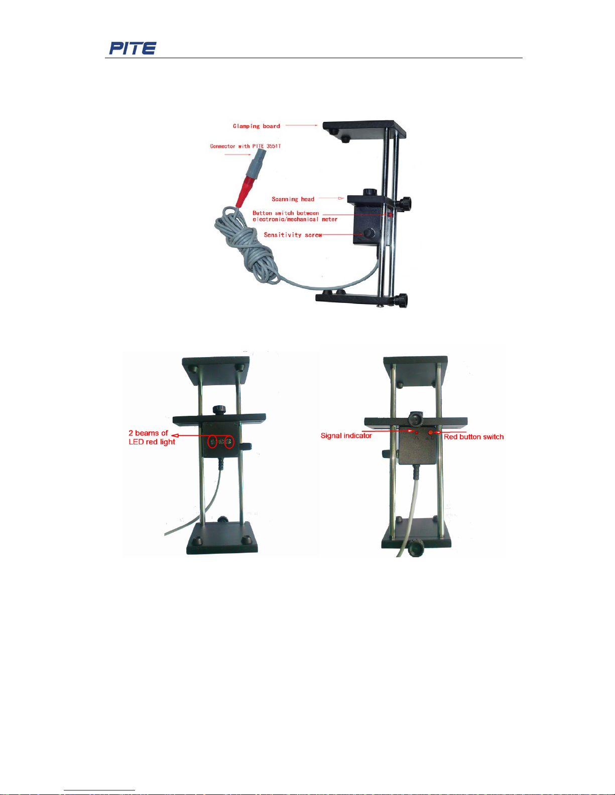
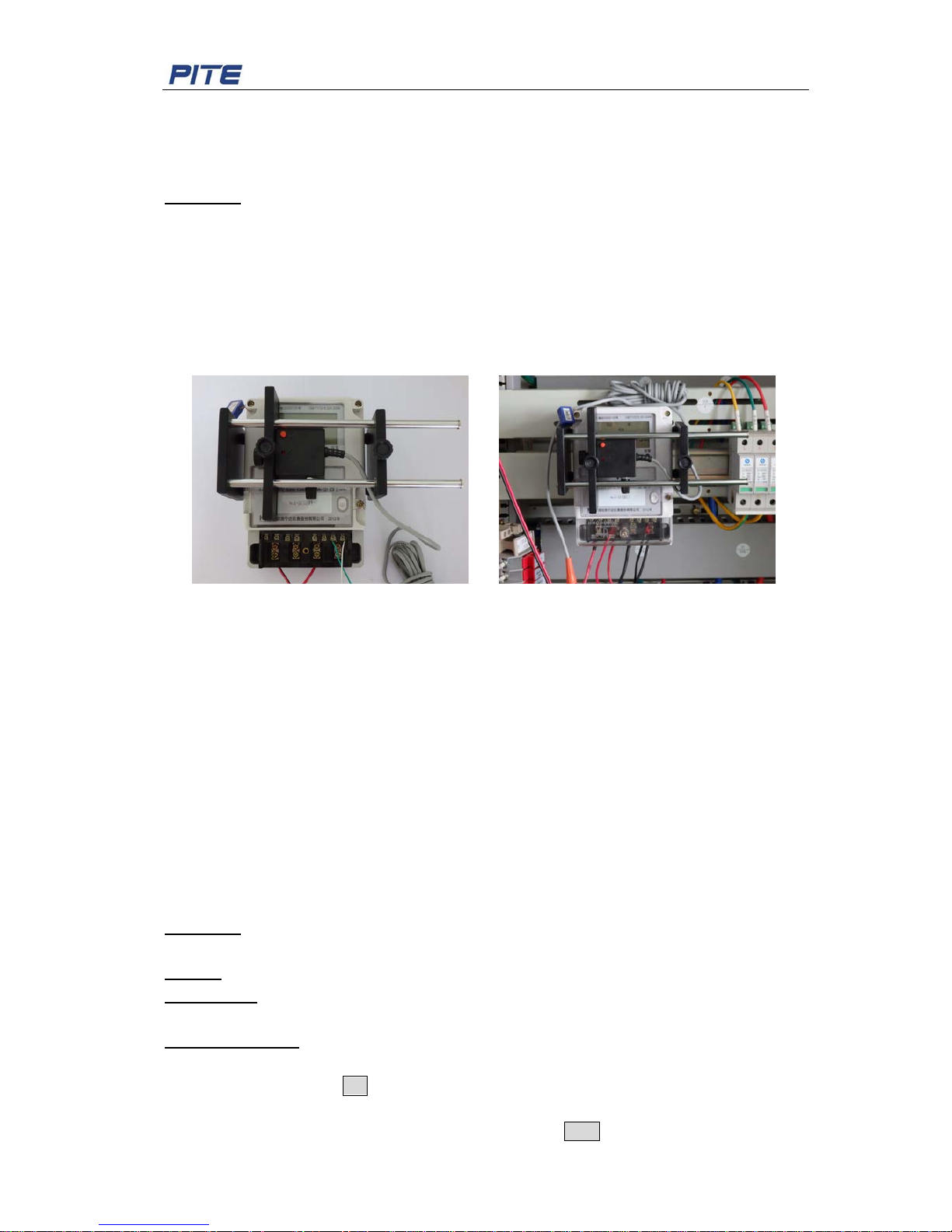
3.1.2.2 Scanning h ead:
This is for auto sensing of meter pulse or meter black mark. For detailed operation instruction,
please refer to below:
Fig 3.1.2.2A Side
Fig 3.1.2.2B Front Fig 3.1.2.2C Back
To use the scanning head properly to test bot h mechanical meter and d igit al meter, please refer
to the instruction below:
1) Connect the scanning hea d w ith pu lse in put p ort ( labele d with letter “P”) of PI T E 3551 T an d
switch on the PITE 3551T.
2) Adjust the distance of two clampin g board o f scanning head bracket according to the siz e o f
power meter. Make the dist ance of two cla mping boa rds 20 to 30m m shorter than t he meter
size and pull the two clamping boar ds to clamp on the meter.
3) To measure mechanical meter, press the red button on the scanning head. A djust
position of scanning head to ma k e t he t w o beams of LED red light focus on the tested
meter disc. Distance of scanning head and meter is around 10-20mm. It is bett er t o ma k e
the two beams of red light as one be am by adjusting the distance.
Page 11
PITE 3551T User Manual
10
4) Adjust the sensitivity screw on the scanning head until the signal indicator is constantly on.
Then slightly adjust the screw to the opposite direction to make the signal indi cat or O FF
when there is no black mark. At this s ensitivity position, the indicator should be ON when
there is black mark passing (sign al output).
5) If the signal indicator is constant ly on or off, please adjust the scanning head to focus the
LED beams on the black mark.
6) In measurement of electr onic m et ers, please focus the two beams of LED r ed li ght on
the pulse output port of electroni c m et er . Then press the red button on the scanning head
to make it popup. When there is pulse output from the power meter, t he signal indicator will
be ON (flash at the same time with meter output pulse). Otherwise it will be OFF.
7) If the signal indicator is constant ly on or off, please adjust the scanning head to focus on
the pulse output port of meter or adjust the sensitivity screw.
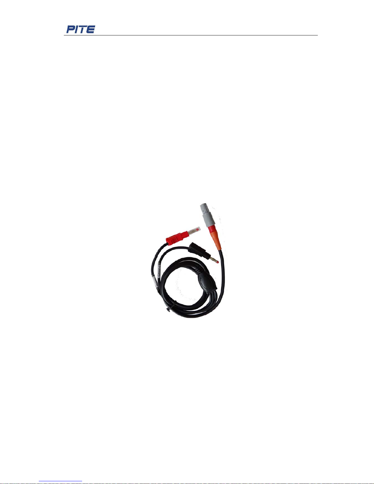
Operation of pul s e input lead:
For meter pulse collecti on of digital meter, you could also use pulse input lead. One end (round
socket) is connected with PIT E 3551T socket “P”. The other end (red and black connectors) are
connected respectively with pulse output ”+” and pulse output ”-“ of digit al meter.
Pulse input lead and scanning head have the same result to collect digital meter pulse.
Fig 3.1.2.2D Pulse input lead
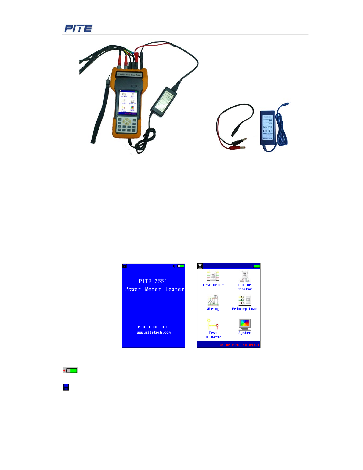
Quick power supply:
With the quick power supply lead, PITE 3551T could get power supply directly from the power
meter that is under mea surement, no need to get power from built-in battery. You need to firstly
connect it with the power adaptor, then connect the adaptor with PITE 3551T charging socket.
Red line of power supply lead is connected with one of the 3 phase (L1, L2 or L3) voltage
socket on PITE 3551T, and black line is connected with Neutral socket. Exemplified picture for
connection is as below:
Page 12
PITE 3551T User Manual
11
Fig. 3.1.2.2 Wire connection Fig. 3.1.2.3 Quick supply lead plus power adaptor
Before the measurement, you will need to do system setting first for curr ent cla mp range, wiri ng
type, CT ratio and so on. For detailed instruction, please refer to 4.2.2 Parameter Setting.
DANGER: To avoid electric shock and short-circuit, please carefully connect the testing
clip/probes with the testing sources.
3.1.3 Instrument Menu
Switch the power button a t t he side o f the main un it to power on PITE 3551T. Click any point o n
starting screen and you will see the main menu with different testing functions and setting as
below:
Fig 3.1.3
Meaning of icons on the menu:
Battery icon on the right top indicates the power status of battery. If it is low, please
charge it before using.
on the left top is for screenshot. To save the current screen, please firstly connect the USB
drive and double click this icon. The screen will be copied in the USB driv e.
01-02-2013 13:31:41: It is time display. For time setting, please refer to 4.2.3 Date & Time
Setting. You could also set screen standby t ime there.
NOTE: The screen will automatically become dark for power saving after the standby time (l i ke
30 seconds). To restart it, please touch any point of the screen.
Page 13
PITE 3551T User Manual
12
3.1.4 Battery Charging
You have two ways to get power supply for PITE 3551T main body: built-in rechargeable Li-ion
battery or quick power supply lead.
If you need to use the battery for operation, make sure that the main unit has enough power
before measurement. When bat tery power get s low, please charge it timely with power adaptor .
WARNING: To avoid electric shock, please always connect the power adapter to the AC outlet
before connecting it to the Test er .
3.2 Measure Different Meters
Select “ Test M eter” in PITE 3551T main menu, you will see the following screen with testing
function for different types of meters and metering equipments. We will explain them one by
one in the following context.
Fig 3.2
3.2.1 Three Phase Metering Unit
Low-volt metering unit, or metering equipment, is the composition of power meter and Current
Transformer (CT). This measurem ent functi on will require t he r ig ht range of current clamps.
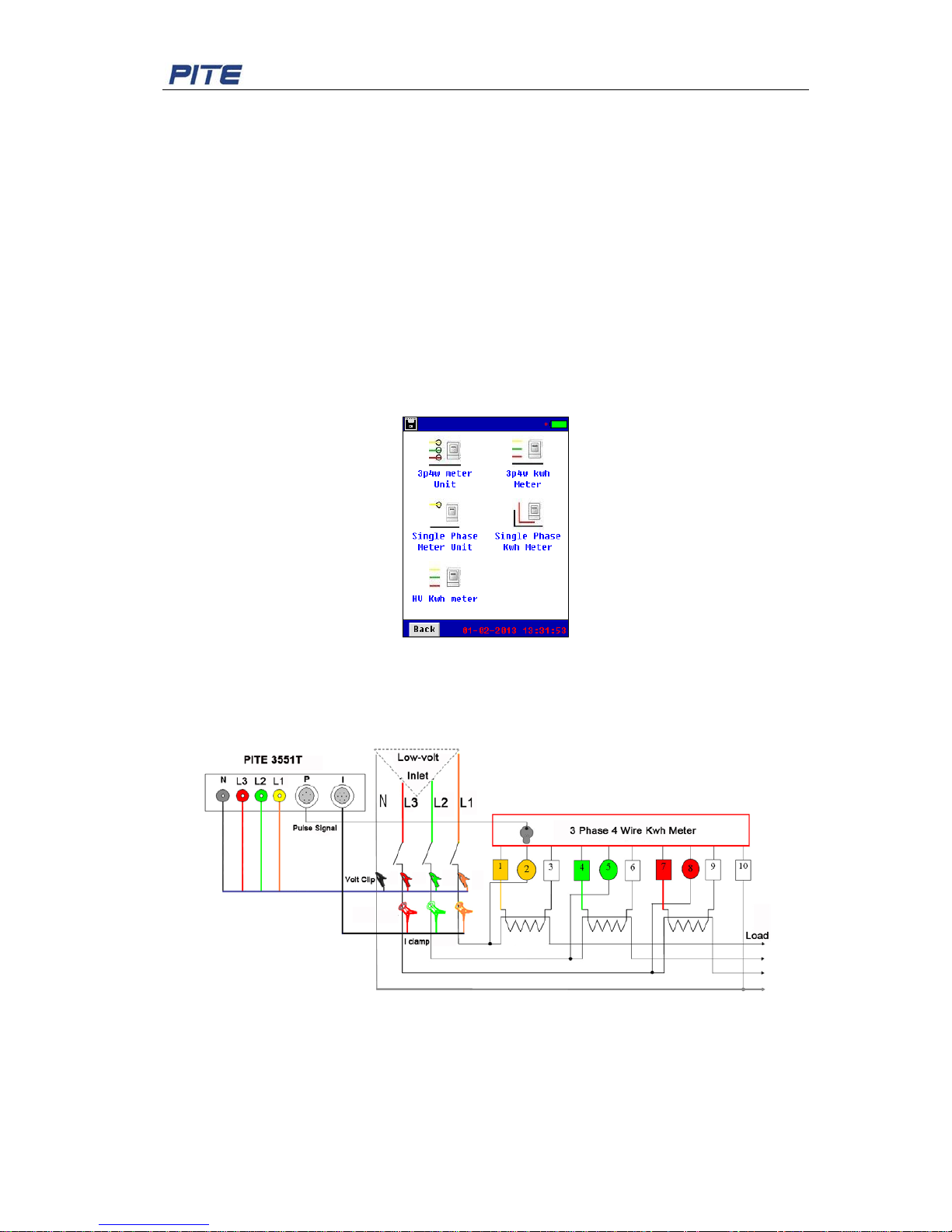
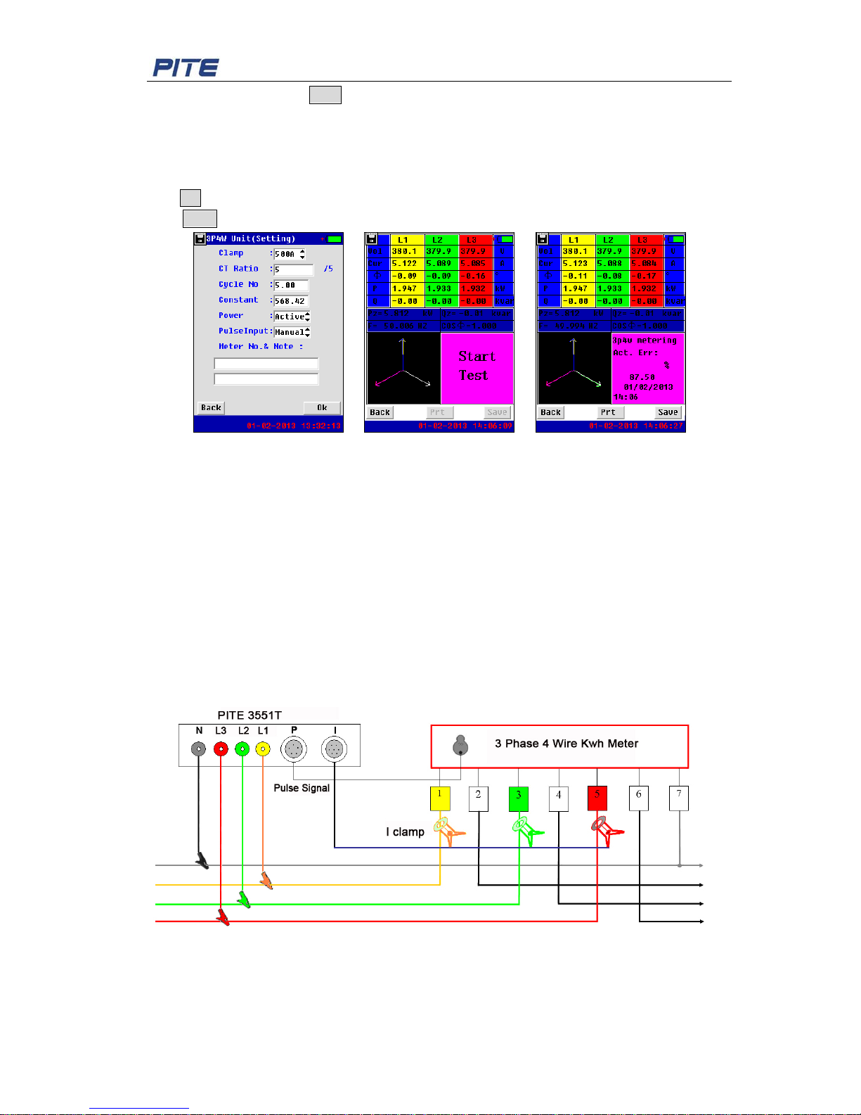
Fig 3.2.1.1 Wiring instruction
Wiring Instruction:
As per the above graph, please connect the c urrent clam ps with the relevant 3 phase line of L1,
L2 and L3 before metering unit (inlet). Connect voltage clips with load line before the power
meter in the succession of Neutral, L1, L2, and L3. After parameter setting in PITE 3551T menu;
you could start measur ing to check the general error of metering unit.
Page 14
PITE 3551T User Manual
13
Menu Setting:
After all cables and clamps are well connected, select (double-click it, same hereafter) “3p4w
Meter Unit” under “Test Meter”, you will come to the step f or parameter setting in Fig 3.2.1.2.
“Cycle No” means total cycles that mechanical power meter rot at es or tot al pul ses o f electr onic
meter during measurement. You will need to manually count circle numbers of power meter if
the tester does not come with scanning head. If you have scanning head, please use it as per
instruction described previously. As long as th e scannin g head se nse the rot ati on of mechan ica l
meter aluminum disc or pulse o f electronic meter, indicat ing light will be on.
Below is just one way of connection with power meter horizontally. You could also connect it
vertically.
.
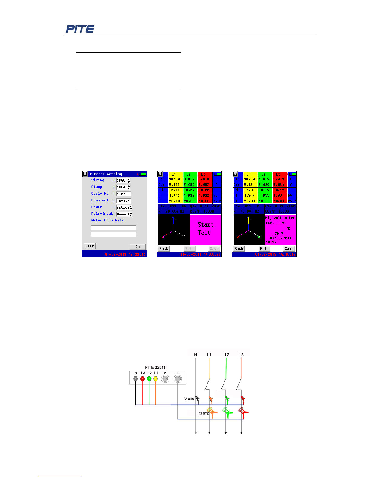
Fig. 3.2.1.2 3.2.1.1.3
When the scanning head is connected with power meter, it will continuously sense the meter
output pulse. For example, if you set the cycle number as 6, the tester will continue to sense
the meter pulse and keep calculating meter accuracy. Every time when you hear the sound
BEEP, there is testing result displaying on the screen. The longer time PITE 3551T measures,
the more accurate you will get . Generally cycles running for 2-3 minutes will b e enough.
NOTE:
1) This way of using scanning head is same to all the other testing functions where
scanning head is used.
2) Outside strong lighting will affect the signal sensing of scanning head. In case of strong
lighting, you are suggeste d to block the light properly for more accurate measurement.
“Constant” number is generally attached to power meters with so me other met er p ara met er. Its
unit is imp/kW·h or imp/kvar·h.
“Power” is selected as per type of the power meter: Active power and Reactiv e pow er.
“Pulse input” has two options. When there is scanning head, please se lect “S ca.h”. Otherwise,
select “Manual” for manual operat ion (cycle counting manually).
“Meter No. & Note” is self-defined. It will help you manage data well with PITE PC software.
After above setting, click OK to confirm. Measurement will start automatically when there is
scanning head. And testing result will displayed when time is up with indication of BEEP.
If there is no scanning head, you need to click the button Start to begin the test, observe the
Page 15
PITE 3551T User Manual
14
cycle number, and click Stop when all setting cycles are calculated (Fig 3.2.1.3 and Fig
3.2.1.4).
In the screen of Fig 3.2.1.4, you could see example of testing result with percentage of error (if
any). To zoom in the vector, just click it (dark area on left bottom). Click any point to zoom out.
To print the testing result, please firstly connect the optional thermal printer with main unit and
click Prt.
Click Save to have a screenshot or save the testing result.
Fig 3.2.1.2 Fig 3.2.1.3 Fig 3.2.1.4
NOTE:
1) Error indication of “-” (negative) in t esting result m eans t hat t he power meter records les s
power than it should do. “+” (positive) means that the power meter records more power
than it should do. This indication has the same meaning in other testing function of PITE
3551T.
2) All screenshots described in this user manual are only for example purpose. Testing
result may vary in different circumstances and conditions.
3.2.2 Three Phase Kwh Meter
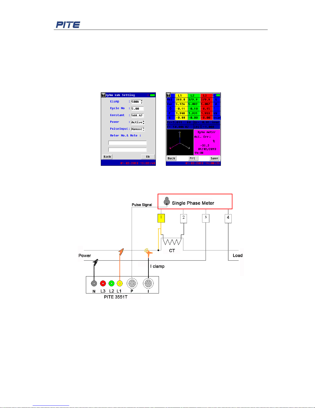
This function is used when kwh meter is not connected with CT. PITE 3551T is used for direct
measurement of low-volt kw h meter.
Fig 3.2.2.1 Wiring instruction
Wiring Instruction:
Connect the voltage c lip s in t he succ ession o f Neutral, L1, L2 and L3 with relevant terminal o f 3
phase 4 wire kwh Meter. Put the current clamps around power cords for L1, L2 and L3 before
Page 16
PITE 3551T User Manual
15
kwh Meter. After menu setting, read the PI TE 3551T main unit to get the kw h Meter error if any.
Menu Setting:
After all cables and clamps are well connected, select “3p4w Kwh Meter” under “Test Meter”,
you will come to the step for par ameter setting in Fig 3.2.2.2.
Please input all paramet ers related to the power meter and start t he measurement as
instruction described in 3.2.1 Three P hase Metering Unit.
Fig 3.2.2.2 Fig 3.2.2.3
3.2.3 Single Phase Metering Unit
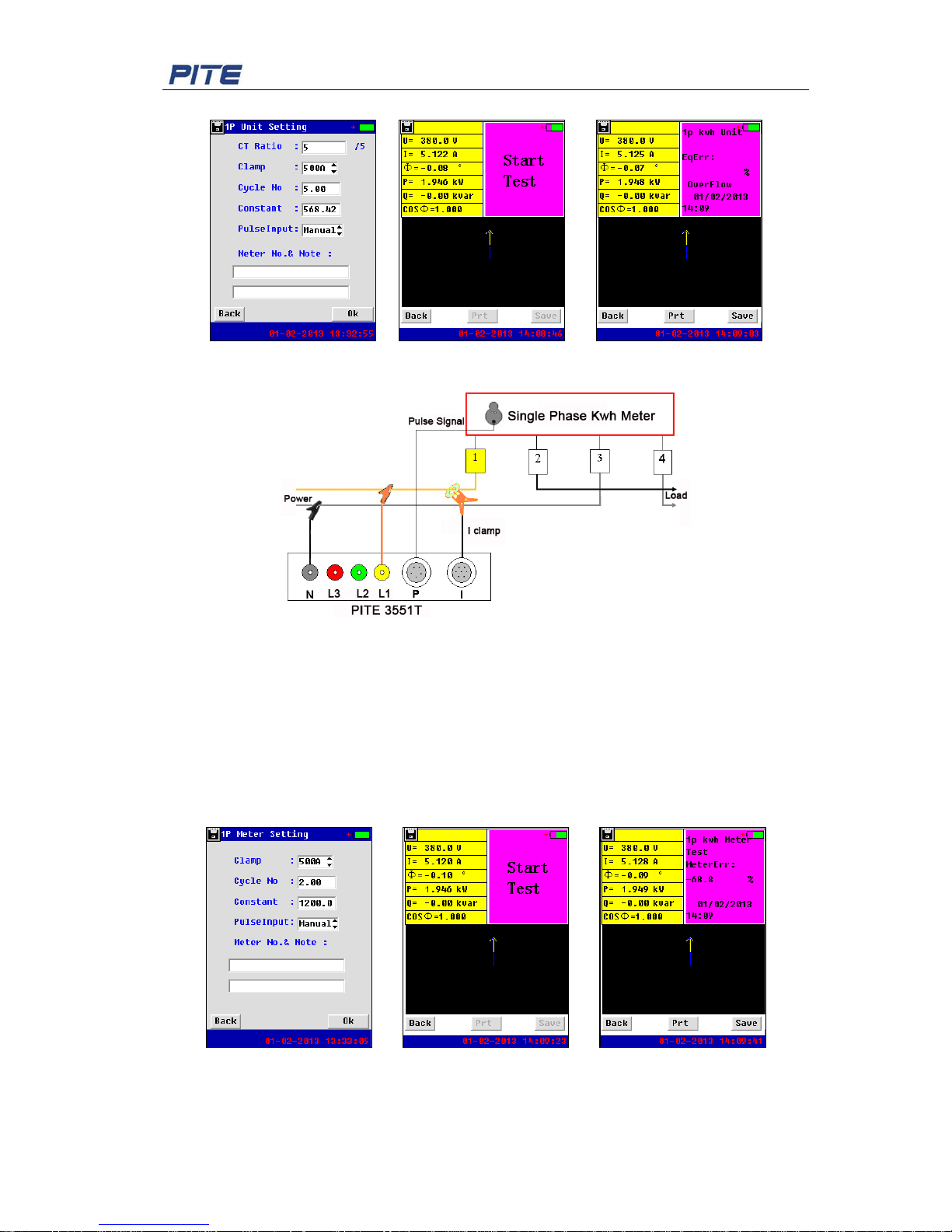
Fig 3.2.3.1 Wiring Instruction
Wiring Instruction:
Connect the current clamp of L1 and then clamp it aroun d t he liv e wire before the single phase
metering unit.
For voltage testing leads, please firstly connect Neutral and L1 with PITE 3551T main body,
and then connect them in the succession of N and L1 with terminals of null line and live wire on
single phase metering unit.
Menu Setting:
Select “Single Phase Meter Unit ” under the menu “Te st Meter” for par amet er setting.
Page 17
PITE 3551T User Manual
16
The setting on the PITE 3551T is same as 3 phase 4 wire metering unit described before.
Fig 3.2.3.2 Fig 3.2.3.3 Fig 3.2.3.4
3.2.4 Single Phase Kwh Meter
Fig 3.2.4.1 Wiring Instruction
Wiring Instruction:
Connect the current clamp of L1 with th e liv e w ire before the single phase meter.
For voltage testing leads, please firstly connect Neutral and L1 with PITE 3551T main body,
and then connect them in the succes sio n of N and L 1 wit h terminals o f null line and live w ire on
single phase power meter.
Menu Setting:
Select “Single Phase Kwh Meter ” under the menu “Te st Meter” for parameter setting.
The setting on the PITE 3551T is same as 3 phase 4 wire metering unit described before.
Fig 3.2.4.2 Fig 3.2.4.3 Fig 3.2.4. 4
3.2.5 High-volt Kwh Meter
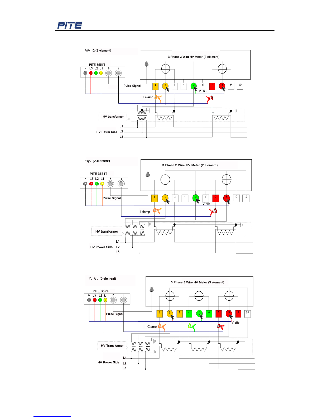
For the measurement of high-volt kwh power meter, there are three ways of wire connections
based on different power meter s: V/V-12 (2-element), Y/y。(2-element) and Y。/y。(3-element).
Page 18
PITE 3551T User Manual
17
Their wire connections ar e as below:
1) V/V-12 (2-element)
Fig 3.2.5.1
2) Y/y。(2-element)
Fig 3.2.5.2
3) Y。/y。(3-element)
Fig 3.2.5.3
Page 19
PITE 3551T User Manual
18
Wiring Instruction:
1) For power meter with 2-element (3p3w)
Connect the voltage testing clips (L1, L2 and L3) with relevant voltage terminal of kwh
meter. Put L1 and L3 current clamps around relevant c onnect i ng lines between kwh meter
and CT secondary.
2) For power meter with 3-element (3p4w)
Connection of voltage testing clips are same as that of 2-element meter. L1, L2 and L3
current clamps are put around relevant connecting lines between kwh meter and CT
secondary.
Menu setting:
Select “HV Kw h Mete r” under menu “Test Meter“ for parameter setting before measurement.
For power meter with 2-element, please select wiring type as 3 phase 3 wire. For power meter
with 3-element, please select 3 phase 4 wire.
Then input all the other param et er s ac cordingly to carry out the measurement.
Fig 3.2.5.4 Fig 3.2.5.5 Fig 3.2.5.6
3.3 Meter Online Monitor
3.3.1 Low-volt Metering Unit
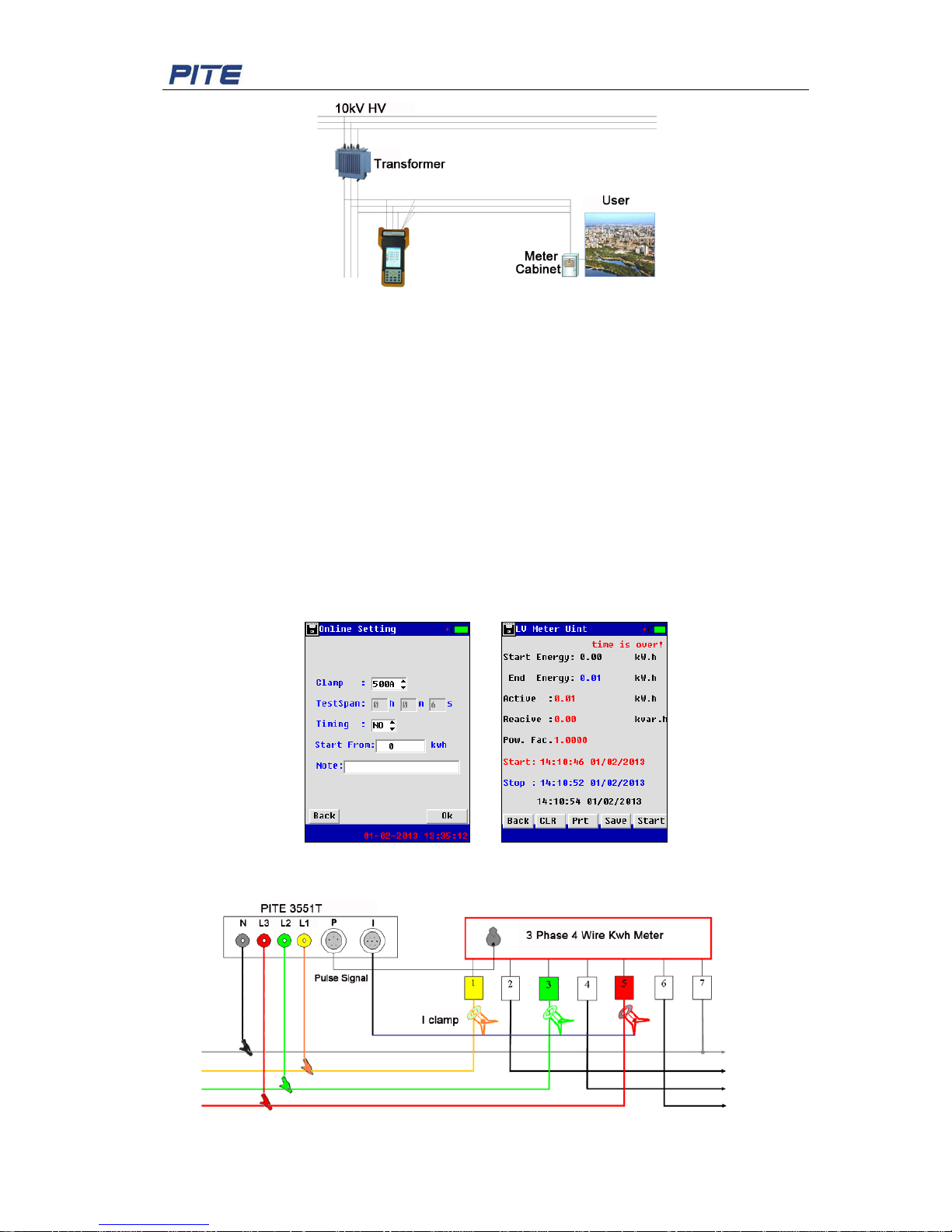
In this function, the PITE 3551T p lays the role a s an evaluat ion power meter. It could be applied
in different voltage l ev els of dif ferent wirin g struc tures. Without stopp ing t he circuit, PITE 3551T
can be temporarily installed in the inlet of metering unit or low-volt load outlet in the power
system. It monitors and records active and reactiv e ener gy. Without disturbing electricity users,
it checks meter errors . This fun ction also helps check if there is pre-meter electricity theft or not.
Fig 3.3.1.1 Wiring Instruct ion
Page 20
PITE 3551T User Manual
19
Fig 3.3.1.2 Wiring Instruct ion 2
Wiring Instruction:
PITE 3551T is connected with low-volt inlet or after main switch of high-volt transformer
secondary side to test power consumption. By comparison with the user’s power meter in the
same time period, you will know if user’s power meter works normal or not.
For wire connection in the circuit, please connect voltage testing leads (clips) with inlet lines in
the succession of N, L1, L2 and L3. Put the current clamps around the three phase i nlet lines.
Menu Setting:
Select “LV Meter Unit” under “Online Monitor” for parameter setting as screen in Fig 3.3.1. 2.
When you select timing as “Yes”, the monitoring will automatically start and stop after the
setting time span (“TestSpan”). And measurement result will be a ut omatically saved.
If timing is selected as “No”, you need to manually start and stop the measurement. Also need
to save the result manually.
Fig 3.3.1.3 Setting Fig 3.3.1.4 Result
3.3.2 Low-volt Kwh Meter
Fig 3.3.2.1 Wiring Instruction
Page 21
PITE 3551T User Manual
20
Wiring Instruction:
Connect the voltage clips in the succession of N, L1, L2 and L3 with relevant terminal of 3
phase 4 wire kwh Meter. Put the current clamps around power cords for L1, L2 and L3 at
current transducer second ar y outlet before kwh Meter .
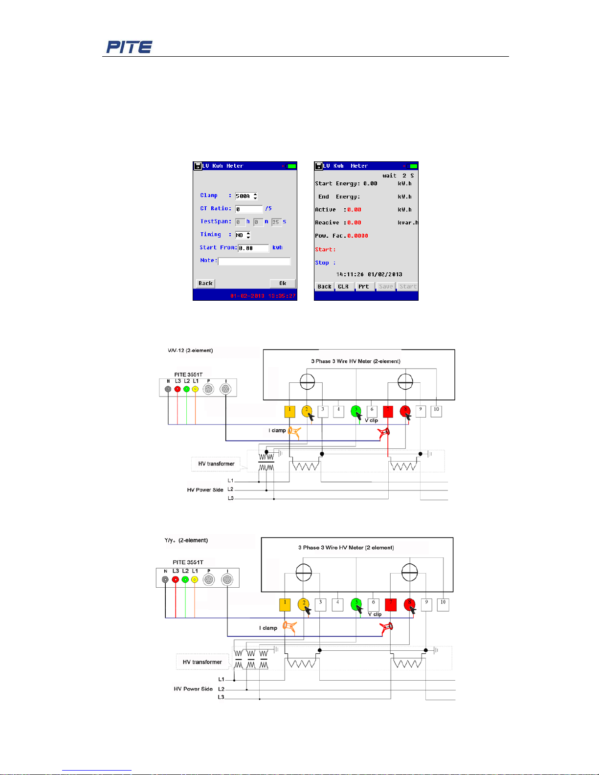
Menu Setting:
Except CT ratio, other parameter setting in the menu is same as that of Low-volt Metering Unit
described before.
Fig 3.3.2.2 Fig 3.3.2.3
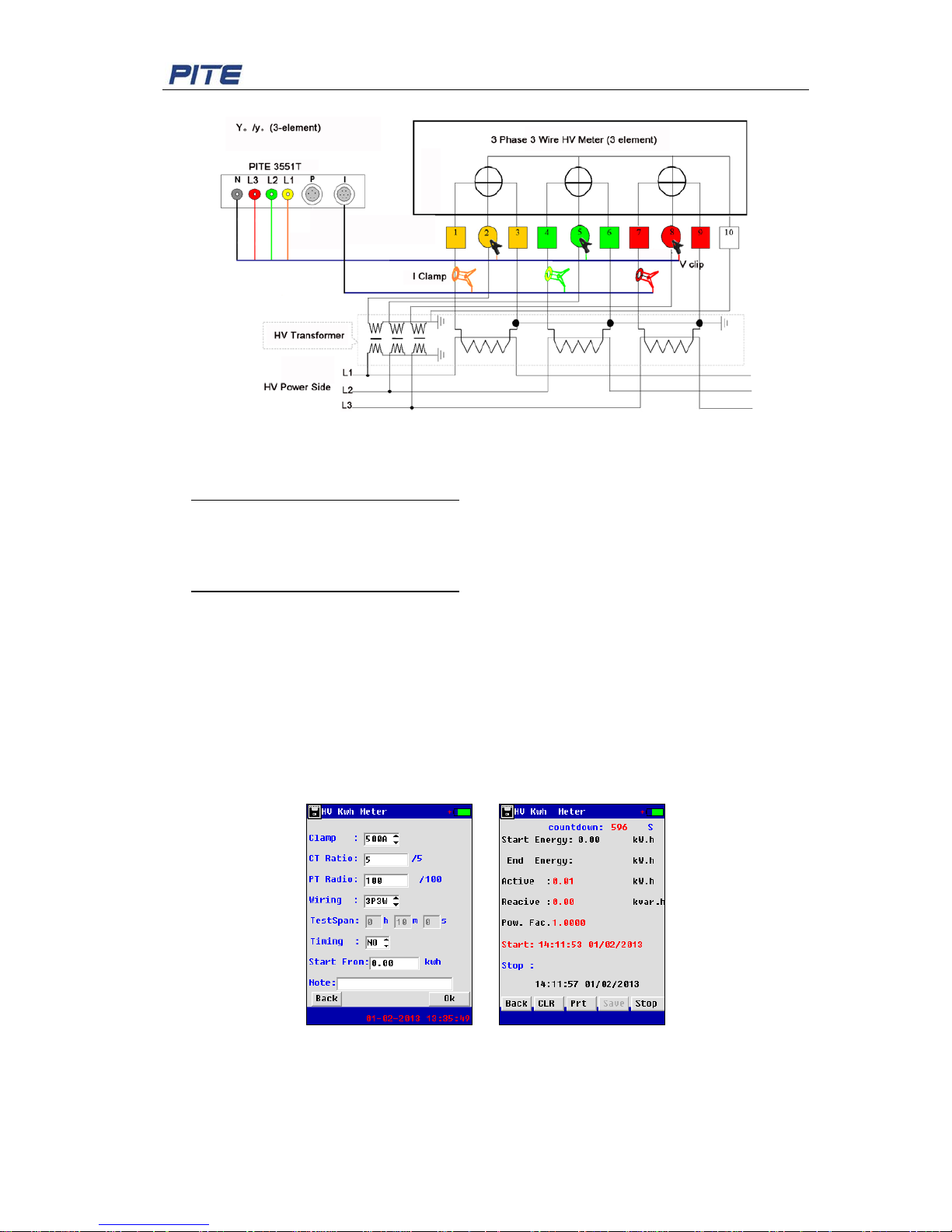
3.3.3 High-volt Kwh Meter
1)
Fig 3.3.3.1
2)
Fig 3.3.3.2
Page 22
PITE 3551T User Manual
21
3)
Fig 3.3.3.3
Wiring instruction:
1) For power meter with 2-elem ent ( 3p3w )
Connect the voltage testing clips (L1, L2 and L3) with relevant voltage terminal of high-volt
kwh meter. Put L1 and L3 current clamps around relevant connecting lines between kwh
meter and CT secondary.
2) For power meter with 3-element (3p4w)
Connection of voltage testing clips are same as that of 2-element meter. L1, L2 and L3
current clamps are put around relevant connecting lines between CT secondary and kwh
meter inlet.
Menu Setting:
Select “HV Kwh Meter” under menu “Online Monitor“ for parameter setting before
measurement. For power meter with 2-element, please select wiring type as 3 phase 3 wire.
For power meter with 3-element, please select 3 phase 4 wire.
Then input all the other param et er s ac cordingly to carry out the measurement.
Fig 3.3.3.4 Fig 3.3.3.5
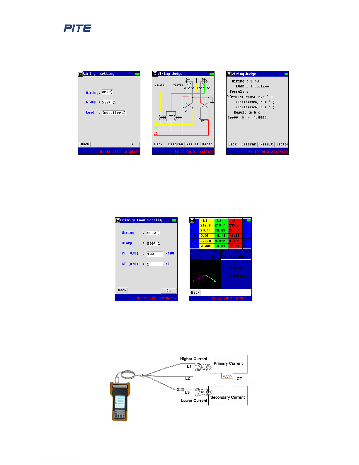
3.4 Judgment for Wire Connection
When the PITE 3551T is connected with the circuit, this function will help judge if the wire
Page 23
PITE 3551T User Manual
22
connection is correct or no t. In the menu set ting, wiri ng type is sel ected betw een 3 phas e 3 wire
and 3 phase 4 wire. It has two types of load: inductive and capacitive. After the menu setting,
the PITE 3551T can ju dge wire conn ecti on in di f fer ent way s and prov ide c orre ction c oefficient if
wire connection is incorre c t .
Fig 3.4.1 Fig 3.4.2 Fig 3.4.3
3.5 Measure Primary Load
In electric circuit, when main circuit has high voltage and big loads, meter testers could not be
used to measure loads directly at high-volt side. With the function “Primary Load”, we can view
the parameter of transformer primary load by measuring transformer secondary.
In the menu setting, just need to PT and CT ratio as screen below:
Fig 3.5.1 setting Fig 3.5.2 testing result
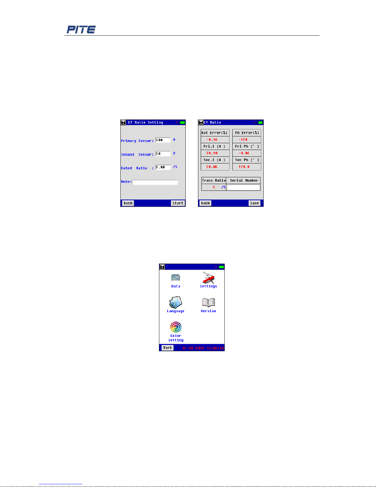
3.6 Test CT Ratio
For this measurement function, you will need to add another current clamp. So you will have
one current clamp of higher range (e.g.500A) and another lower (50A). It will use current
clamps of L1 and L3 to CT ratio, phase angle error and so on.
Fig 3.6 Wiring Instruction
Page 24
PITE 3551T User Manual
23
Wiring Instruction:
Connect L1 with higher range current clamp (like 500A) and L3 with lower range (like 50A).
Then connect L1 current clamp with CT primary (higher current) and connect L3 current clamp
with CT secondary ( lower cur r ent ) .
Menu Setting:
In parameter setting scree n ( Fig 3.6.1), input the r elev ant cur rent r ange of L1 and L3, and input
the rated ratio to start measuring. Rated ratio is generally labeled on t he CT.
Testing result will display as scr een like Fig 3.6.2.
Fig 3.6.1 Fig 3.6.2
4. SYSTEM MANAGEMENT
Select “System” in the main men u, you will come to the screen for system manage m ent as the
screen below. This will include data management, system setting, language setting, version
information and setting for t hr ee phase color code.
Fig 4
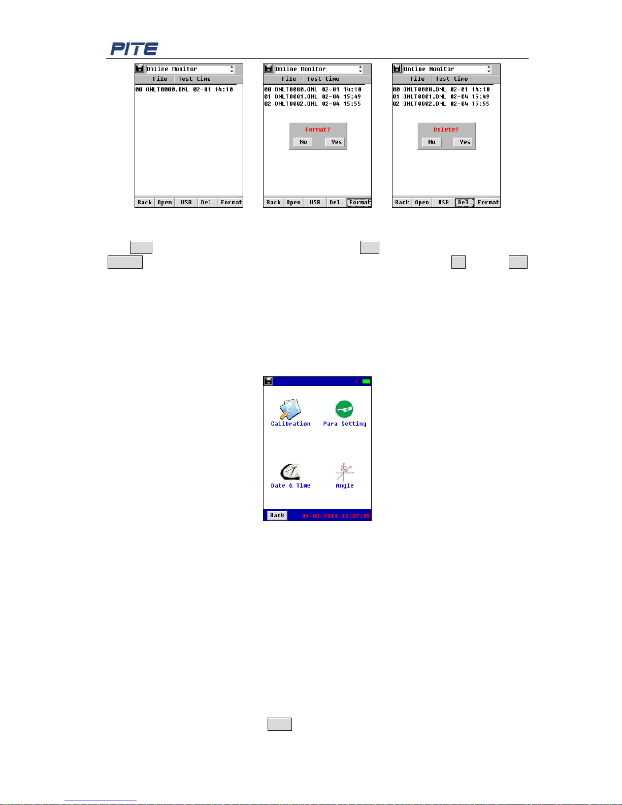
4.1 Data Management
All testing data you have saved bef or e c ould be viewed, transferred to PC or deleted direct ly in
data management. Screen with detailed information will be displayed as below by going to
“System””Data”.
Page 25
PITE 3551T User Manual
24
Fig 4.1.1 Fig 4.1.2 Fig 4.1.3
To save the data in your PC for analyzing, insert the USB drive properly, select the data and
click USB. To delete the data, select the target and click Del.. To format all testing data, click
Format directly. Warning screens w ill pop up as F ig 4.1.2 and Fig 4.1.3. Click No to exit or Yes
to confirm the operation. Please make sure that you have saved the data pro per ly . Once
deleted or formatted, they could not be recovered.
4.2 System Setting
Select “ Setting” under the menu “System”, we will come the steps for parameter calibration,
parameter setting, ti me setting and phase angle setting.
Fig 4.2
4.2.1 Parameter Calibration
This is for calibrating the parameter of PITE 3551T. All data have been well calibrated in PITE
factory before the product is sent our cu stomers. For test ing accura cy, you are not suggested t o
carry out this operation if unnecessary. If you really need it, please contact your supplier or
PITE for detailed separate instruction.
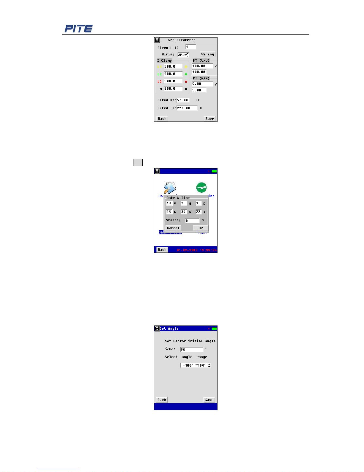
4.2.2 Parameter Setting
Select “Para Setting” under the menu “Setting”, you will come to the screen below for
parameter setting. This is required by most measurement functions for three phase power
meters. Circuit ID is self-defined. In different places, you will need different ID numbers to
distinguish them from others. Parameters like current clamp, PT ratio, CT ratio are input as per
real situation. After the setting, click Save to exit.
Page 26
PITE 3551T User Manual
25
Fig 4.2.2
4.2.3 Date & Time Setting
Select “Date & Time” under the menu “Setting”, you will come to the scr een b e low. Change the
time if necessary and click OK to save the change.
Fig 4.2.3
The PITE 3551T sc reen will automatically become dark f or pow er saving after the standby t i m e
(like 30 seconds).
4.2.4 Phase Angle Setting
This will enable you to set differe nt way of display for phase angle in t hree phase circuit. Please
go to “Angle” under menu “Setting”. You will see the screen as below for initial angle setting
and angle range (optional for -180
o
-180 o and 0~360o).
Fig 4.2.4
Page 27
PITE 3551T User Manual
26
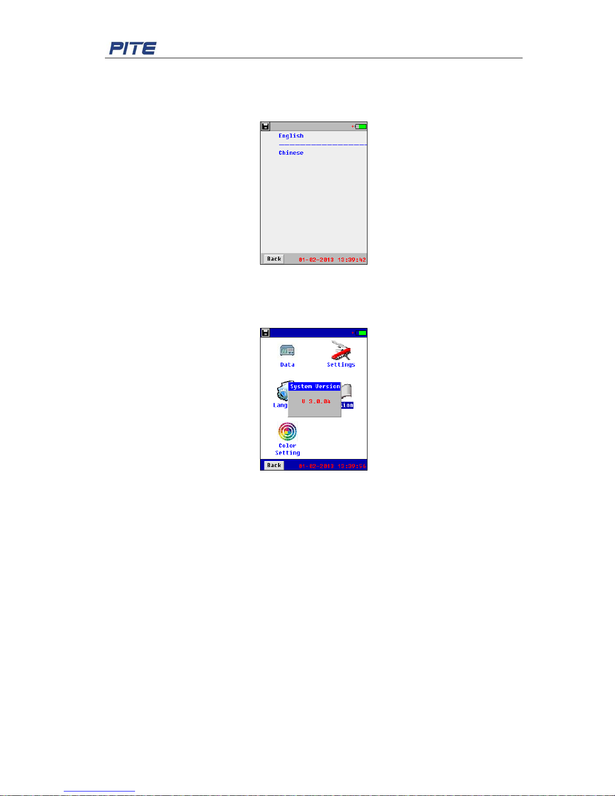
4.3 Language Selection
Click “Language” under the menu “System” and select the language needed in the following
screen:
Fig 4.3
4.4 Firmware Version and Update
Click “Version” under menu “System” , you will see the firmware version.
Fig 4.4
Firmware Update:
PITE constantly updates its program as per customers’ need. To update the unit, please follow
the steps as below:
1) Copy the two files (named “Program.hex” and “SCRIPT00.txt”) from PITE and paste under
the root directory of PITE USB drive.
2) Connect the USB drive wit h PITE 3551T main body via USB converter and restart the unit.
3) Firmware update will be done i n very short time.
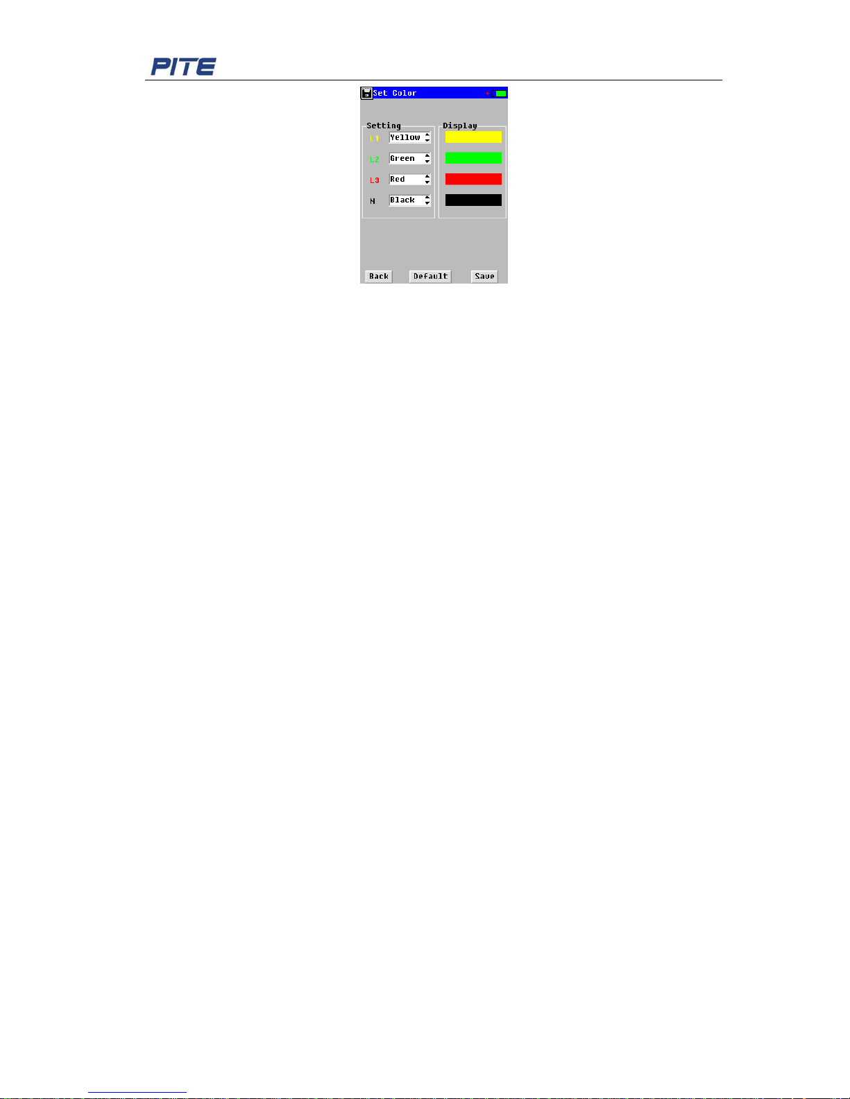
4.5 Voltage Color Setting
For standards of three p hase volt age col or code in dif fere nt countri es, PITE pro vide custo mized
settings. To do this, please go to “Color Setting” under the menu “System”, you will see the
screen below for setting color of L1, L2, L3 and Neutral.
Page 28
PITE 3551T User Manual
27
Fig 4.5
5. SERVICE AND M AINTENANCE
5.1 Maintenance
1). Cleaning
Clean PITE 3551T main unit and its accessories (current clamps, voltage probes, etc.) with
a damp cloth and a mild soap. Do not use abrasives, solvents, or alcohol, as they can
deform or discolor the Tester and the accessories.
2). Storage
Place the PITE 3551T and all its accessories into the case after using. It is unnecessary to
remove the battery pack even storing it for a long time. However, the battery will discharge
itself gradually overtime. So please charge the batteries periodically (like once a month) to
keep them in optimal cond ition.
3). Battery Maintenance
3.1). Charging the Batteries
Connect the battery charger to the power supply then to PITE 3551T m ain unit. After
the battery is full charged, it will automatically enter overcharge protection. No
damage will occur to the Tester even if you charge the batteries overtime.
3.2). Extending the Battery Life
To obtain optimized performance of the battery, discharge the battery completely and
then recharge it fully.
5.2 FAQ
Below are the frequent asked questions that you might come across when usi ng PITE 3551T:
Q: The PITE 3551T cannot start up. Wha t is going wrong?
A: The batteries may be power off. If so, charge it properly.
Q: The Tester kee ps beeping when it’s on.
A: Power of battery is low. Charge it for a while and try again.
Q: The Tester is power off suddenly during tes t ing.
A1: The battery may be out of condition. Replace it with a new one and try again.
A2: The testing leads m ay be well connected. Unplug the testing leads and p lu g again.
Page 29
PITE 3551T User Manual
28
6. PITE 3551T DATA MANAGEMENT
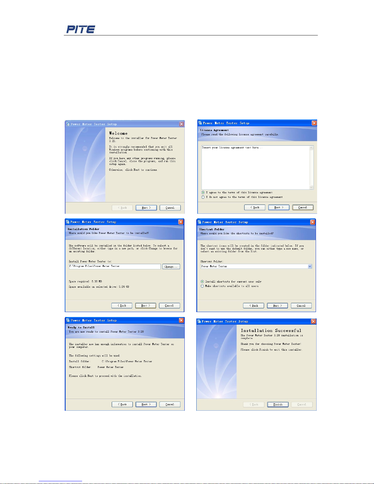
6.1 Software Installation
Double-click the software name like “Power Meter Tester System v3.20 Setup.exe” in the PITE
USB drive to start installation of the software. Click “Next”select ”I agree to the terms of this
license agreement” Click “Next”Change installation path if necessary Click “Next”
select ”Install short cuts for current unsers only” Click “Next” Click “Next” C lick “Fin ish” to
complete the software i nstallation. Below screenshot s ar e for your reference:
Fig 6.1
6.2 Software Operation
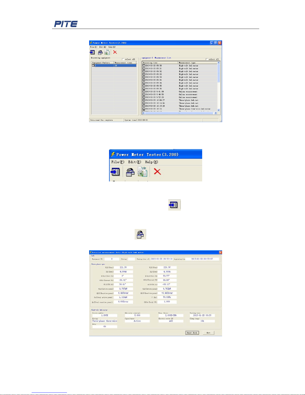
After installation is finished, double click the icon named “Power Meter Tester v3.20” on
Page 30
PITE 3551T User Manual
29
computer desktop to run the software. You will see the main screen as below:
Fig 6.2.1
It has 4 shortcut icons on the menu, when you move the mouse icon on each of them, their
functions will display as: I mp or t data, View data, Export exce l, Delete.
Fig 6.2.2
Import testing data
Go to menu “File” click “import” or click the button
directly select the testing data to
import.
View testing data
To view data, please click the button
, and then you will get a chart as below.
You could also choose “measuring type” and doub le clic k, y ou will see detailed testing data.
Fig 6.2.3
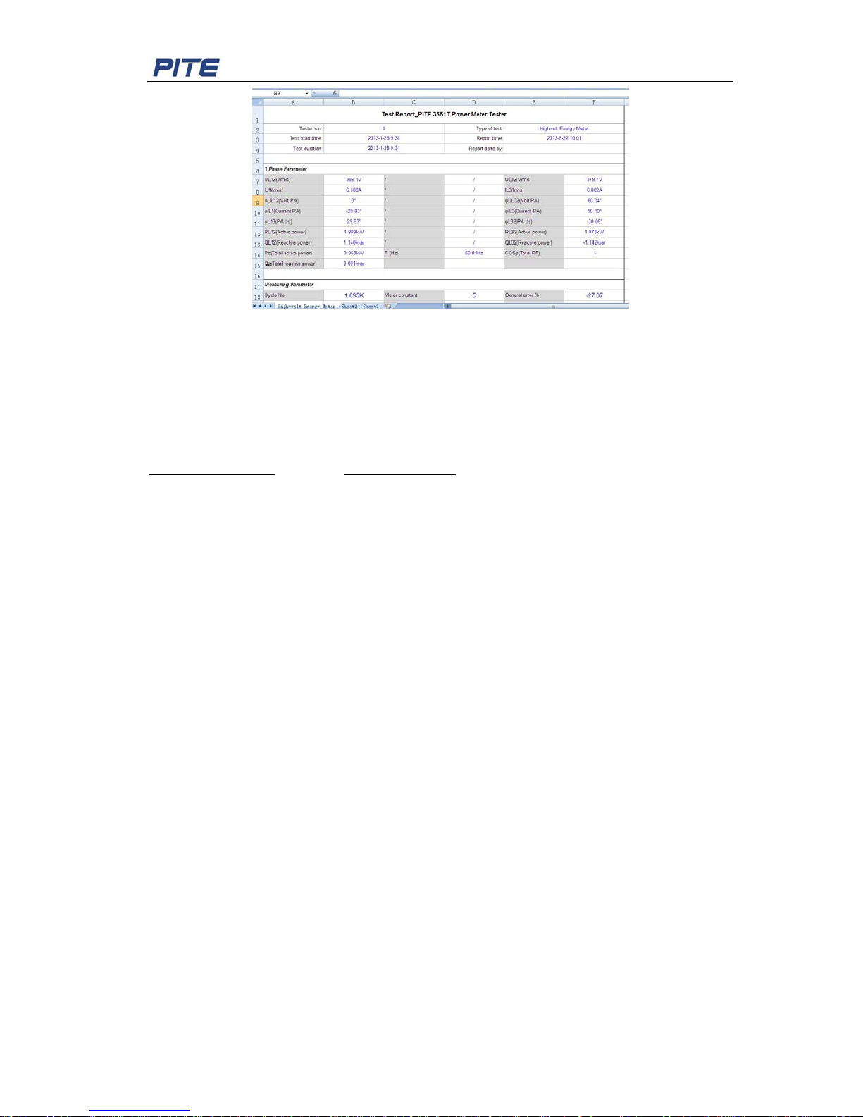
Export testing data
In the screen of “detailed measurement data”, click “Export Data”, the testing data will be
exported in the format of Microsoft Excel and saved. The excel is bellow:
Page 31
PITE 3551T User Manual
30
Fig 6.2.4
7. ORDER INFORMATION
PITE TECH. INC.
4/F, Bldg A, Chiwan Industrial Park, Shaodi Rd., Chiwan, Shekou Area, Shenzhen, China.
TEL: +86-755-2680 5759 FAX: +86-755-2688 0310
[email protected] www.pitetech.com
 Loading...