

Page 1
Service Manual
for the
Pitco Frialator
Literature # L20-155 Rev 0 Patent Pending Manufactured in
Printed 9 May 1997 The United States of America
Page 2

FOR YOUR SAFETY :
Do not store gasoline or other flammable vapors
or liquids in the vicinity of this or any other appliance.
TO THE PURCHASER
POST IN A PROMINENT LOCATION INSTRUCTIONS TO BE FOLLOWED IN THE
EVENT THAT AN OPERATOR SMELLS
GAS. OBT AIN THIS INFORMATION FROM
YOUR LOCAL GAS SUPPLIER.
WARNING:
IMPROPER INSTALLATION, ADJUSTMENT , AL TERA TION, SERVICE OR MAINTENANCE CAN CAUSE PROPERTY DAMAGE, INJURY OR DEATH. READ THE INSTALLATION, OPERATING AND MAINTENANCE MANUALS THOROUGHLY BEFORE INSTALLING OR SERVICING THIS
EQUIPMENT.
WARNING
DO NOT use an open flame to check for gas leaks!
Keep all open flames away from the machine at all
times.
WARNING
Ensure that the machine can get enough air to keep
the flame burning correctly . If the flame is starved
of air it can give off a dangerous carbon monoxide
gas. Carbon Monoxide is a clear odorless gas that
can cause suffocation.
WARNING
Blocking the flue will also cause the unit to overheat. DO NOT obstruct the flow of combustion/
ventilation or air opening around the machine. Ensure that you meet the minimum clearances specified in the installation instructions. Adequate clear ance around the unit is necessary for servicing and
proper burner operation.
WARNING
The power supply must be disconnected before servicing or cleaning the unit.
WARNING
DO NOT supply the fryer with a gas that is not
identified on the data plate, located on the inside of
one of the doors of the machine. If you need to
convert the machine to another type of fuel, contact your dealer or Authorized Blodgett Service
Agency.
WARNING
Machines equipped with casters and a flexible
power cord, must be connected to a gas supply with
a Quick-Disconnect device. This quick disconnect
must comply with ANSI Z24.41. T o limit the movement of the unit without depending on the connector or quick disconnect, a restraining cable must
also be installed.
WARNING
Use only a B/C or A/B/C extinguisher that contains the dry chemical Sodium Bicarbonate or
Potasium Bicarbonate should be used to extinguish
any fires.
WARNING
When the fryer is in its operating location, lock the
casters and reattach the restraining device to the
rear of the machine.
WARNING
Shortening, when it is at cooking temperatures, is
very HOT and DANGEROUS! Use extreme caution when handling! Use the proper protective gear
such as insulated gloves, aprons, face shield and
sleeves when handling hot shortening. DO NOT
attempt to move any machine that has hot oil in it.
Allow the oil to cool to room temperature or drain
the oil into a suitable container before moving the
fryer.
i
Page 3

ORIGINAL EQUIPMENT LIMITED WARRANTY - TURBOFRY 2000
General Warranty
Pitco Frialator, Inc. warrants to the original user of its T urbofry 2000 cooking appliance that said appliance and related equipment will be free from
defects in material and workmanship under normal use for a period of one (1) year from the date of installation, with appropriate documentation, subject
to the following additions, exceptions, exclusions and limitations.
What is covered
This warranty is limited to the repair or replacement at the Company’s option, without charge, of any part found to be defective within the warranty
period and reasonable expenses incurred for freight and material for the installation of such part; in addition, the Company’s obligation shall be limited to
reimbursement for normal labor on such parts.
Pitco Frialator, Inc. agrees to pay the G.S. Blodgett Corporation Authorized Service and Parts Distributor, for any labor and material required to
repair or replace, at the Company’s option, any part which may fail due to defects in material or workmanship during the above general warranty period.
Fry T anks
In addition, the Company warrants to the original user of any fry tank to be free from defects for a period of ten (10) years from the date of
manufacture. Labor and freight shall be the responsibility of the user. This shall only obligate the Company to repair or replace, at its option, any fry tank
which it determines to be defective. Claims under this item shall be supported by a statement detailing the defect, and the Company may require the return
of the fry tank claimed to be defective.
Computer or Digital Cooking Controller
In addition, the Company warrants to the original user of any Cooking Computer or Digital Controller to be free from defects for a period of two (2)
years,from the date of manufacture. During the two (2) year period all charges involved in the replacement of a Pitco Computer or Digital Controller will
be the responsibility of Pitco Frialator Inc.
How to Keep Your Warranty in For ce
€ Make sure any shipping damages are reported immediately. Damages of this nature are the responsibility of the carrier.
€ Install the unit properly. This is the responsibility of the installer and the procedures are outlined in the manual. Do not install it in a home
or residence.
€ Maintain the unit properly. This is the responsibility of the user, the procedures are outlined in the manual.
What is NOT covered under this Warranty
€ Adjustments, such as calibration, leveling, tightening of fasteners or plumbing or electrical connections normally associated with initial
installation are not covered under this warranty. These procedures are outlined in the installation manual.
€ Damaged due to flood, fire or other acts of Nature are not covered under this warranty.
€ If the unit is used for a purpose other than for which it was intended or designed, resulting damages are not covered under the warranty .
€ Failures due to erratic voltage or gas supplies are not covered under the warranty.
€ Material alterations or modifications from the condition in which the unit left the factory are not covered under the warranty.
€ Units with unreadable, obliterated or removed serial number rating plates are not covered by the warranty.
€ Any parts other than Genuine OEM parts from Pitco Frialator, Inc. or its Authorized Parts and Service Distributors are not covered by the
warranty.
€ Any other failure which is not attributable to a defect in materials or workmanship is not covered bt the warranty.
This warranty specifically excludes parts which wear or would be replaced under normal usage, including, but not limited to, electric lamps, fuses,
interior or exterior finishes and gaskets.
Limits to the Warranty
Outside the United States of America and Canada, this warranty is limited to the replacement of parts and Pitco Frialator , Inc. will not bear any other
expense be it labor, mileage, freight or travel.
Charges for mileage over one hundred (100) miles, travel time over two (2) hours, overtime, and holiday charges are not covered under this warranty .
These charges are the responsibility of the individual or firm requesting these services.
If any oral statements have been made regarding the appliance, these statements do not constitute warranties and are not part of the contract of sale.
This limited warranty constitutes the complete, final and exclusive statement with regard to warranties.
THIS LIMITED WARRANTY IS EXCLUSIVE AND IS IN LIEU OF ALL OTHER WARRANTIES WHETHER WRITTEN, ORAL OR IM-
PLIED, INCLUDING, BUT NOT LIMITED TO ANY WARRANTY OF MERCHANT ABILITY OR FITNESS FOR A PARTICULAR PURPOSE OR
W ARRANTY AGAINST LATENT DEFECTS.
Limitations of Liability
In the event of a warranty or other claim, the sole obligation of Pitco Frialator, Inc. will be the repair or replacement, at the Company’ s option, of the
appliance or the component part. This repair or replacement will be at the expense of Pitco Frialator, Inc. except as limited by this warranty statement. Any
repair or replacement under this warranty does not constitute an extension in time to the original warranty. Parts covered under this warranty will be
repaired or replaced, at the Company’s option, with new or functionally operative parts. The liability of Pitco Frialator, Inc. on any claim of any kind,
including claims based on warranty, express or implied contract, negligence, strict liability or any other legal theories will be exclusively the repair or
replacement of the appliance. This liability will not include, and the purchaser specifically renounces any right to recover special, incidental, consequential or other damages of any kind, including, but not limited to, injuries to persons, damage to property, loss of profits or anticipated loss of the use of this
appliance.
If any provision of this warranty is unenforceable under the law of any jurisdiction, that provision only will be inapplicable there, and the remainder
of the warranty will remain unaffected. The maximum exclusion or limitation allowed by law will be substituted for the unenforceable provision.
How to Obtain W arranty Service
First direct your claim to the G.S. Blodgett Corporation Authorized Service and Parts Distributor closest to you giving complete model, serial and
code numbers, voltage, gas type, and description of the problem. Proof of the date of installation and/or the sales slip may also be required. If this
procedure fails to be satisfactory, write the National Service Manager , Pitco Frialator, Inc., P. O. Box 501, Concord, NH. 03302-0501. USA
This warranty gives you certain specific legal rights; you may have other rights which vary from state to state.
ii
Page 4

Table of Contents
ORIGINAL EQUIPMENT LIMITED WARRANTY ................................ ii
TABLE OF CONTENTS ......................................................................... iii
SPECIFICATIONS and DATA ................................................................. iv
INTRODUCTION ..................................................................................... 1
How does it work? ................................................................................ 1
230 VAC, High Voltage System ............................................................ 1
24 VAC, Low Voltage System............................................................... 2
Component Recognition - Fry T ank...................................................... 5
Component Recognition - Controls...................................................... 6
PREVENTATIVE MAINTENANCE ....................................................... 7
Daily Cleaning ...................................................................................... 7
W eekly Cleaning................................................................................... 7
Vacuum Gauge Inspection .................................................................... 7
Boil Out Procedure ............................................................................... 7
Air Filter Inspection .............................................................................. 9
Inspect O-Rings .................................................................................. 10
Service T echnician Inspection ............................................................. 10
TROUBLESHOOTING........................................................................... 11
COMPONENT TROUBLESHOOTING ................................................ 12
T emperature Probe .............................................................................. 12
Relays ................................................................................................. 12
Hi Limits ............................................................................................. 12
Drain Valve & Return Valve Switches................................................. 12
Transformer......................................................................................... 12
Blower ................................................................................................ 13
Pressure Switch ................................................................................... 13
Ignition Control Modules .................................................................... 13
Ignitors ................................................................................................ 13
PARTS ...................................................................................................... 15
General................................................................................................ 15
Entrance Box Assembly............................................................... 16 - 17
SCHEMATICS..................................................................................18 - 20
700268 Rev C - Page 1, Left Side of schematic.................................. 18
700268 Rev C - Page 1, Right Side of schematic ............................... 19
700268 Rev C - Page 2 ....................................................................... 20
iii
Page 5

SPECIFCA TIONS and DAT A
Gas Consumption................................................................................................ 240 kbtu/hr
Efficiency ..................................................................................................................71-73%
Cooking capacity , fries ............................................................................................ 260 lb/hr
Supply V oltage .............................................................................................. 208 - 230 VAC
Control V oltage ........................................................................................................ 24 VAC
Heat up time - Liquid ................................................................................................20 mins
Heat up time - Solid ..................................................................................................25 mins
Minimum melt time - Solid only................................................................................10 mins
Sump Thermostat temp ..................................................................................Open at 135°F
Close at 105°F
Spark Gap ........................................................................... 0.1 ± 0.005" (2.54 ± 0.127mm)
Hi Limit specs .................................................................................................... 435 - 465°F
Burner flame color .........................................................................................Yellowish blue
Blower speed ....................................................................................... Set by Speed control
Ignition lockout time ..................................................................................................15 secs
Pressure switch.................................................................... Open below 0.8" WC (0.2 kPa)
Close above 0.1" WC (0.325 kPa)
Blower Air High Fire Pressure ...............................................................Nat - 5.5 - 5.6" WC
LP - 4.8 - 4.9" WC
Blower Air Low Fire Pressure ....................................................................... Nat - 0.4" WC
LP - 0.4" WC
Gas Pressure at Tap in High Fire Gas Line ....................................................... Nat - 4" WC
LP - 3.5" WC
Heat Time from 250°F to 300°F.................................................................. 2:25 - 3 Minutes
Pump Rate, clean oil, Full Pan to Fry T ank................................... 5 - 5:45 Minutes/Seconds
Pump Rate, clean oil, to empty Circulating System............................................. 45 Seconds
(This is done after the T ank has been cleaned, drained and the filters removed)
Low Fire Orifice Size................................................................... Nat & LP - #54 Drill Size
Hi Fire Orifice Size ........................................................................................... Nat - 0.328"
LP - 0.302"
Air Bleed T ip Orifice ............................................................................. Nat - #52 Drill Size
LP - #45 Drill Size
Air collar Size ..................................................................................................... Nat - 1.06"
LP - 1.165"
Minimum Gas Pressure Requirments ................................................... Nat & LP - 5.0" WC
Maximum Gas Pressure Requirements.................................................. Nat & LP - 14" WC
iv
Page 6

v
Page 7
INTRODUCTION
How does it work?
The development of the TURBOFRY 2000 fills the
needs of the food industry that have been, until now ,
unattainable. They are:
1. Continuous filtration of the food oil.
2. Crispier than ever fried food coatings due to convection currents.
3. High production from a high efficiency heat transfer system.
Continuous filtration of the cooking oil provides clean,
clear oil, even through busy periods. This means
breaded particles do not settle on heating surfaces and
burn, which in turn means longer oil life and lower
oil costs. The clean oil produces foods with coatings
free of burnt food particles that look and taste more
appetizing. Turbofry 2000 has an advanced filter system that makes clean up quick and easy. The main
filters trap the larger crumbs and can be lifted out for
easy cleaning and replacement.
The Turbofry 2000 uses a heating process, within the
cooking area, known as "Convection", foods cook
with crisper coatings because hot oil is forced between
the individual pieces of food, the breading or outer
coating gets seared quickly before the food can absorb as much oil as with a standard fryer. This will
produce a finished product that is much lower in absorbed oils.
There are two parts to the control system in the Tur bofry 2000 fryer, the 230 VAC or high voltage circuit and the 24 VAC or low voltage circuit.
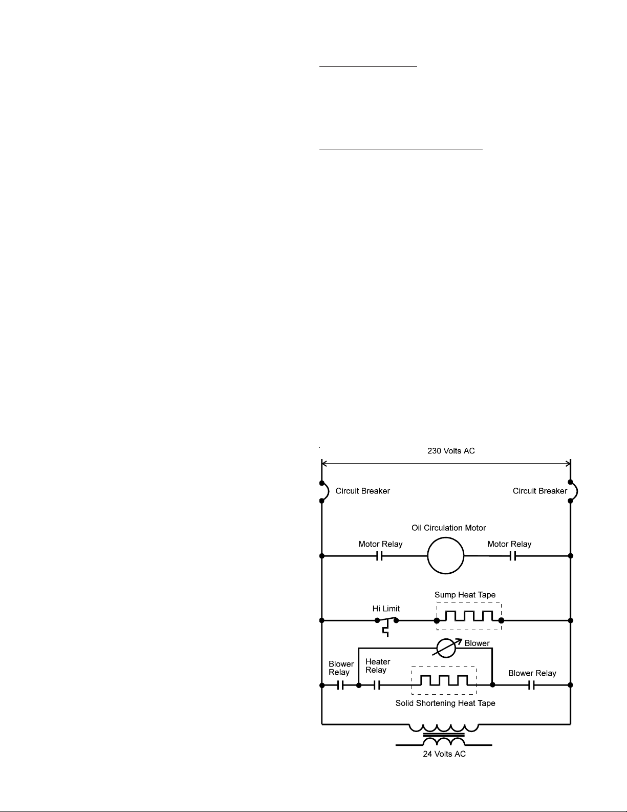
230 VAC, High Voltage System:
230 VAC is applied to the machine -
• The Pump Motor Relay switch contact are supplied with 230 VAC.
• The Sump Heat System is supplied with 230
V AC. When the Sump T emperature Switch closes
the Sump Heat Tape will start to heat.
• The Motor Relay switch contacts will be supplied with 230 VAC. This relay will be explained
later in this manual.
• On machines equipped with the Solid Shortening Option the switch contacts of the Heat Tape
Relay will also be supplied with 230 VAC. This
relay is controlled by the Pipe Temperature
Switch.
• The primary coils of the Transformer will be supplied with 230 VAC. At this point the 24 VAC,
low voltage circuit will become energized.
The Turbofry 2000 has a high efficiency gas combustion system that transfers heat more efficiently than
regular fryers. The high input rate in conjunction with
a large heat transfer surface area give this fryer the
ability to cook high capacity loads effortlessly .
When installing the Turbofry 2000 follow the instructions in the Installation and Operating Manual.
1
Page 8
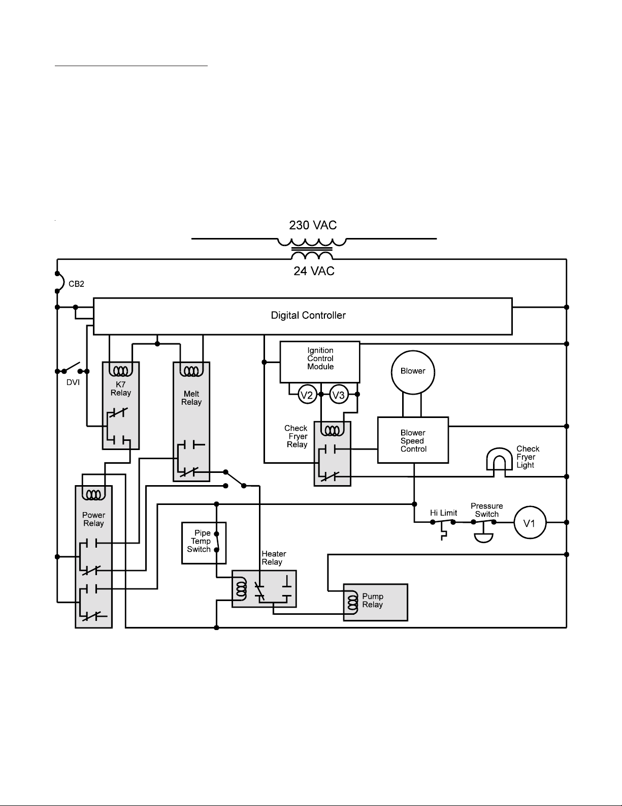
24 VAC, Low Voltage System:
Digital Control Condition - Power supply ON Digital Control OFF.
• 24 VAC is supplied to the Digital Temperature Controller.
• The Drain Valve Switch is supplied with 24 VAC. If the Drain Valve is closed the switch will allow 24
VAC to be supplied to the Drain Interlock connection at the Controller .
• The Power Relay switch contacts will also be supplied with 24 VAC.
2
Page 9

Condition - Digital control is switched ON but there is NO demand for heat:
• 24 VAC is supplied to the On Relay (K7) relay which energizes and supplies 24 VAC to the coil of the
Power Relay (K1).
• The Power Relay (K1) energizes and supplies 24 VAC to following places:
→ Hi Limit Switch (S2) - If the Hi limit (S2) is closed 24 VAC is supplied to the Pressure Switch (PS1),
the Pressure Switch (PS1) will close and supply 24 VAC to the Gas Valve (V1) when the Blower
(M2) comes up to speed.
→ Melt Relay (K2) - if the Digital Control (A1) is in Melt Cycle the Melt Relay (K2) is energized and
the circuit will be open. If the Digital Control (A1) has completed the Melt Cycle the Melt Relay (K2)
will be de-energized and the Pump Override Switch (S1) will be supplied with 24 VAC.
→ Blower Speed Control (VR1) - the Blower Speed Control (VR1) will cause the Blower (M2) to run
in Low Fire mode until it receives a signal from the Check Fryer Relay (K5) to tell it to run in the
High Fire mode.
→ Pipe T emperature Switch (TS1) - When the temperature in the filter piping falls below a certain level
the Pipe Temperature Switch (TS1) will close and supply 24 VAC to the Heater Relay (K6). In this
state the Heat Tape (HR2-HR6) will be supplied with 230 VAC and will continue to heat until the
Pipe T emperature Switch Opens at its designed temperature.
Condition - Demand for heat (All Controls):
• 24 VAC is supplied to the switch points of the Check Fryer Relay (K5). Since the Check Fryer Relay is
energized by the Ignition Control Module when it runs in High Fire Mode it will remain de-energized and
the Check Fryer Light (DS1) will be illuminated.
• 24 VAC is supplied to the Ignition control Module at terminal #6. The Ignition Control Module will cause
a spark at the Ignitor (PR1) and supply the Gas Valve (V2) with 24 VAC. At this time the Low Fire flame
will ignite. The Ignition Control Module will seek a flame sense signal from the Ignitor (PR1). The
Ignition Control Module will then supply 24 VAC to the Gas Valve (V3) and the High Fire Flame will
run. (Under normal working conditions it should take 2.6 - 4 seconds for the High Fire Flame to light.)
The same 24 VAC signal supplied to the Gas Valve (V3) is also supplied to the Check Fryer Relay (K5).
When the Check Fryer Relay energizes it will stop supplying 24 VAC to the Check Fryer Light and start
supplying 24 VAC to the Blower Speed Control. The Blower speed will then increase to High Fire speed
which will sustain the air demand for High Fire.
Condition - Auto Pump start (All Contr ols):
• The Pump Relay (K4) is supplied with 24 VAC from the Heater Relay (K6) and, if all of the following
conditions are met, the Circulation Pump (M1) will begin to run:
• When the Controller is turned off the Power Relay (K1) is de-energized which supplies 24 VAC to one
side of the Pump Override switch (S1). If the pump is NOT running the Pump Override Switch (S1) will
be in the open condition. In the open position the Pump Override Switch will be in the correct position for
Automatic Pump Start. When the Control is first turned on it will send a 24 VDC signal to the coil of the
Melt Relay (K2). This will energize the relay and open the circuit to the Pump Override Switch. When
the Control has exited the Melt Cycle or run past the Minimum Melt Time it will stop supplying the Melt
Relay (K2) with 24 VDC and the Pump Override Switch will be supplied with 24 VAC At this time,
assuming the Sump T emperature is above 135°F (57°C) and the Heater Relay is de-energized the Pump
Relay (K4) will be supplied with 24 VAC and the Circulation Pump will be supplied with 230 VAC.
3
Page 10

Condition - Computer Control Option:
• In order to supply power to the computer the OFF/ON ST ART Switch (S6) must be in the ON position.
The following conditions must be met before the machine can begin heating:
→ The Drain Valve Interlock Switch (S3) must be closed.
→ The Interlock Relay (K10) must have been energized by pressing the OF/ON/ST AR T Switch (S6) to
the ST AR T position and releasing. The Interlock Relay (K10) will stay latched until the Drain V alve
Switch (S3) is opened or the power is cut to the machine. When the Interlock Relay (K10) is latched
it will supply a continuous 24 VAC to the Power Relay (K1). When the Computer Control (A2) is
supplied with 24 VAC it will supply the Control Transfer Relay (K8) with 24 VDC, if there is an open
circuit condition on the Probe (PR1) the Computer Control (A2) will stop supplying the Control
Transfer Relay (K8) with 24 VDC causing it to de-ener gize and allowing the Alternate Thermostat
(S5) to control the Heating of the oil. When the Computer Control (A2) calls for heat it will supply 24
VDC to the coil of the Heat Demand Relay (K9) which will cause the machine to heat in a manner
previously described.
4
Page 11

Component Recognition - Fry tank:
The Turbofry 2000 uses a new frying and filtering
technology , therefore it is important that you become
familiar with the major components inside and outside of the fry tank. The following drawing and index shows these components and their uses:
1. Flue opening - The HOT exhaust gases from combustion will rise from this opening.
2. Burner Heat Tube - Combustion takes place
within this tube. The heat radiates out from this
tube and from the sides of the fry tank.
3. Hi Limit Probe - The Hi Limit is the safety device that will shut the machine down should the
temperature become excessively high.
4. T emperature Sensing Probe - This probe is used
by the Digital/Computer Control to sense the
actual temperature of the oil.
5. Oil Circulation Tube Assembly - The filtered oil
is returned to the fry tank through this tube. It
has many orifices along the underside to direct
the oil streams into the bottom of the fry tank.
There is a handle welded to the end of the tube.
6. Filter Bag Retainers - The Filter Bags "Hang"
on the retainer which fits snugly in the Filter Bag
Housing.
7. Drain - Oil will drain from this opening when
the Drain Valve Handle is opened.
8. Filter Bag Housing Lifting Points - Use the supplied lifting tool to lift the Housing out.
5
Page 12

Component Recognition - Controls:
1. Gas Shut Off Valve.
2. Master Circuit Breaker - Protects all circuits in
the machine.
3. Pump Override Switch - Manually turns the filter pump ON or OFF independently of the current operation mode. This switch is locked out
while the control is in the melt cycle mode.
4. Control Circuit Breaker - Protects the control
circuit only.
5. Check Fryer Indicator Light - Indicates burner
ignition status.
6. Flush Hose Connector - When needed the Flush
Hose is connected here.
7. Pump Outlet Selector - Used to direct the oil to
the Fry Tank or the Flush Hose.
8. Drain Outlet Pipe - Allows the oil to be drained
into the Lower Pan or a high temperature disposal container.
9. Drain Valve Handle - Green.
10. Lower Pan Pick Up Assembly - Connects the
Lower Pan to the Pump Suction Connection.
11. Pump Suction Connection.
12. Sump Screen Assembly - This Screen prevents
any debris from getting into the pump during a
Filter Bag Change procedure.
13. Sump Drain Handle - When this is pulled away
from the Sump Screen Assembly it opens a valve
to drain the Sump so that it can be removed from
the machine safely.
14. Lower Pan Assembly - Holds the cooking oil
while the filter bags are being changed.
15. Digital/Computer Control - Controls operating
and cooking functions (Digital Control shown.)
16. Vacuum Gauge - Shows the status of the main
filters.
17. Pump Inlet Selector Knob - Used to change the
pump inlet from Main Filter to the Lower Pan
Assembly.
18. Oil Circulation Tube Gauge - Indicates when the
Oil Circulation Tube needs cleaning.
6
Page 13

PREVENT A TIVE MAINTENANCE:
In order to keep your new Pitco Frialator Turbofry
2000 operating and looking in top condition it is
necessary to perform a few simple tasks on a daily,
weekly , monthly and quarterly basis. Follow the chart
below to find the frequency at which these Preventative Maintenance Items should be performed:
Cleaning Daily and Weekly
Vacuum Gauge Inspection Daily
Boil Out Monthly or when needed
Air Filter Inspection Every 3 months
Inspect O-Rings on-
Filter Bag Housing Every 3 months
Oil Circulation Tube Every 3 months
Sump Screen Every 3 months
Service T ech Inspection Yearly
Follow the directions outlined below for the instructions on how to perform the given task:
Daily Cleaning:
Bag Removal Tool to lift the complete Filter Bag
Housing out of the machine. Wash the Filter Bag
Housing with soap and water to remove all debris.
Dry thoroughly and install in the machine. Make sure
the Housing is seated correctly before installing the
Filter Bags.
Pump Suction Screen - Follow the instructions outlined in the Main Filter Bag Changing Procedure. Use
an abrasive, NON metallic, scouring pad on persistent stains.
Oil Circulation Tube - Grasp the Oil Circulation
Tube Handle and pull to the right until it is free from
the housing. Lift the Oil Circulation Tube from the
fry tank. The Oil Circulation Tube may be washed
with soap and water. Use a toothpick or similar tool
to push the crumbs and debris out of the circulation
holes. Thoroughly dry the Oil Circulation T ube and
reinstall by carefully aligning the end in the housing,
lower the handle until it is seated on the bracket. Push
the Oil Circulation Tube into the housing until it seats.
It is recommended that, in addition to filtering, the
external components of the fryer be cleaned in the
following manner.
Turn the fryer OFF by pressing the key on the
Digital Control panel, or pressing the power switch
to the OFF position. Using a soft clean cloth to wipe
the exterior surfaces until they are free of oil. A small
amount of non abrasive cleaner may be used on stubborn stains.
Weekly Cleaning:
At least once a week the following preventative maintenance procedures should be performed:
Clean Filter Bag Housing
Clean Pump Suction Screen
Clean Oil Circulation Tube
Clean Fry T ank using the Boil Out procedure
Follow the instructions below for instructions on each
of these items:
Filter Bag Housing - After the oil has been drained
from the Filter Bag Housing use the supplied Filter
Vacuum Gauge Inspection:
Each time that the pump is switched off or the machine shuts the pump off during a Filter Bags Change,
check the Vacuum Gauge to make sure the needle
points to the zero mark. The Vacuum Gauge will only
point to zero when the pump is NOT running. If it
does not point to the zero or very close call an Authorized Service Agency to have the Vacuum Gauge
checked.
Boil Out Procedure:
Periodically it will be necessary to perform what is
known as a Boil Out. This removes baked on frying
oil from the inner surfaces of the fry tank. The best
time to accomplish this is when the oil is ready to be
replaced.
Due to the unique design of the TURBOFRY 2000,
the Boil Out procedure is more involved than that of
a regular fryer. Always use Pitco Fryer Cleaner to
boil out the TURBOFRY 2000. Other cleaners not
approved by Pitco may be harmful to materials used
in the construction of the TURBOFRY 2000. Any
7
Page 14

damage done by the use of other cleaners will not be
covered by the Pitco warranty .
The Procedure has 3 main parts - Cleaning, Neutralization and Rinsing:
Cleaning:
1. Check that the controller is programmed to heat
with a melt cycle, the Digital display will show
. (The Computer display will show
or .)
2. Check the current Set T emperature setting of the
controller. Reprogram the controller to a temperature setting of 200° F . (Follow the instructions in
the appropriate section of this manual.)
Notice - Even though we call this a Boil Out, there is
no need to boil the water . 200°F is hot enough for the
cleaner to work and will prevent the mess and hazards of a boil over .
3. Shut the fryer OFF by pressing the key on
the Digital controller . (Press the OFF/ON/ST ART
switch to the OFF position on Computer controlled machines.)
4. Drain all of the oil from fry tank and filter bags
into the lower pan by opening the Green Drain
Valve (#9, page 6). Remove any pieces of food
that may have accumulated on the bottom of the
fry tank or in the Sump and Sump Screen. Remove the Sump Screen assembly (#12, page 6)
and clear any particles from it. Return the Sump
Screen assembly to its housing and make sure it
is seated. Remove the soiled Filter Bags and install clean ones.
5. Fill the fry tank with water to the OIL LEVEL
mark on the inside of the fry tank.
6. Turn the fryer ON by pressing the key on the
Digital control. (Press the OFF/ON/START
switch to the ON position on Computer controlled
machines.)
Notice - Allow the fryer to heat for 10-15 minutes
until the Digital display changes to (Com-
puters will show ), before adding Pitco
cleaner . Adding cleaner while the fryer is heating up
could cause a boil over . At this time the pump should
have started to circulate the water.
7. Add 8 Ounces by weight of Pitco Fryer Cleaner
to the water. (4 sample packets, supplied with your
new fryer .)
8. Allow the Pitco Fryer Cleaner and hot water to
soak with the pump running for 45 minutes, the
fryer will hold the cleaning compound at 200°F .
9. While the cleaner is soaking, use the white fryer
cleaning brush to scrub all the inner surfaces of
the fry tank, splashback, basket hanger, and the
fry baskets.
10. After 45 minutes, turn the fryer OFF by pressing
and holding the key on the Digital control.
(Press the OFF/ON/START switch to the OFF
position on Computer controlled machines.)
11. Rotate the Drain Outlet Pipe (#8, page 6) to point
outward. Place a heat resistant 3-5 gallon container under the Drain Outlet Pipe. The water
should be disposed of in a responsible manner.
12. Drain the fry tank by slowly opening the Green
Drain Valve Handle (#9, page 6). The used Boil
Out water and Pitco cleaner is safe to pour down
a sink drain.
Notice - The water from the fryer could be hot enough
to damage plastic drain systems. Run cold tap water
as you pour the hot cleaner down the drain to protect
plastic drain systems.
13. Turn the pump on by pressing the Pump Override Switch (#3, page 6) to drain the filters. Allow the pump to run until the Filter Bags are empty
of water. Remove and dispose of the soiled Filter
Bags.
14. Use a Green Scouring Pad or similar Non Metallic abrasive cleaning pad to remove any carbonized deposits from the inner surfaces of the fry
tank. Rinse all surfaces after scrubbing.
15. Remove the Oil Circulation Tube Assembly (#5,
page 5) and rinse it. Rinsing should be done from
the outside of the Circulation holes to the inside
of the tube to prevent plugging the holes, a toothpick or similar tool may be used to clear any
blockages in the holes.
16. If after completing the previous steps, the fry tank
8
Page 15

is not cleaned to your satisfaction, repeat steps 5
through 15. If the fry tank is clean go to step 17.
If the fryer cleaner did not clean the fryer adequately, then Boil Outs should be performed
more frequently to prevent heavy build up.
17. Use clean water to rinse the fryer cleaner out of
the fry tank. Use the brush or a clean towel to
rinse all surfaces that were contacted by the fryer
cleaner. Repeat the rinsing until all surfaces are
free of cleaner residue.
Notice - If you are using the recommended Pitco Fryer
Cleaner (Pitco part Number P6071397) which is a
“Non Caustic” cleaner or another brand Non Caustic
cleaner skip the Neutralization steps (18 through 23).
Neutralization:
18. Fill the fryer with fresh water to the OIL LEVEL
line on the rear of the fry tank. Add 1/2 gallon of
white vinegar to the water.
19. Connect the flush hose to the flush hose fitting.
Start the pump by pressing the Pump Override
Switch (#3, page 6). Let the pump run for 1-2
minutes. Stop the pump. Pull the Pump Outlet
Selector (#7, page 6) to the Flush Hose position,
place the end of the hose nozzle into the fry tank,
and start pump by pressing the Pump Override
Switch. This will neutralize the cleaner in the flush
hose lines. Use the brush or a clean towel to wipe
the neutralizer solution over all the parts that were
cleaned with the fryer cleaner. Once the entire
fryer has been neutralized, drain the fry tank and
filter sump by following steps 12 and 13.
20. Close the Green Drain Valve Handle (#9, page 6)
and fill the fryer with fresh water to the OIL
LEVEL line on the rear of the fry tank. Rinse the
fry tank, splashback, basket hanger, and the fry
baskets. Operate the pump as in step 19.
21. Drain the fry tank and filter sump of all water, by
opening the Green Drain Valve Handle (#9, page
6). This includes removing the Sump Screen Assembly (#12, page 6) and allowing all water to
drain from the sump housing. Replace the Sump
Screen Assembly in the sump housing and return
the Sump Drain Handle (#13, page 6) to its normal operating position.
22. Wipe the fry tank, splashback, basket hanger , and
the fry baskets with clean dry towels to remove
all water. Install the Oil Circulation Tube Assembly (#5, page 5). This completes the neutraliza-
tion part of the Boil Out procedure.
23. Install new filters in the filter sump. Pull the Pump
Inlet Selector Knob (#17, page 6) to the “ Lower
Pan” position.
24. Turn the Drain Valve Handle (#9, page 6) counter
clockwise to the “Closed” position. Use the Pump
Override Switch to start the pump and pump all
of the oil from the lower pan to the fry tank to a
level ½" below the OIL LEVEL mark at the rear
of the fry tank.
CAUTION:
The next step will be very noisy as the fryer evaporates the remaining water in the fry tank and pump
lines. Allow the pump to run the entire time it takes
to evaporate the residual water. If the pump is not
left running, there is a chance that steam could build
up in the unit and discharge hot oil.
25. Turn the fryer on using the key. Enter the program mode to reset the temperature to the original setting as shown in the Operating Manual. The
fryer will now heat the oil and evaporate any remaining moisture.
26. Allow the fryer to heat the oil until all the moisture from the boil out is evaporated. The amount
of time required to do this will vary with the degree of dryness that was achieved during the wipe
down after rinsing, generally it takes 15 -20 min-
utes to dry the oil.
Notice -The best way to tell if the system has dried
out is by the appearance of the oil. When the oil is
dry , there will be no small bubbles visible in the oil.
At this point the fryer can be shut down.
27. Shut the fryer OFF by pressing the key on
the Digital controller. (Press the OFF/ON/START
switch to the OFF position on Computer controlled machines.) Drain fry tank and filter sump
and dispose of the used oil.
28. Fill the fryer with new cooking oil. The Boil Out
is now complete.
Air Filter Inspection:
Remove the 8 screws that hold the Air Filter cover in
place (see page 6), grasp the handle and pull outward
until the entire Air Filter extends out of its housing.
9
Page 16

Inspect the air Filter for dirt and debris. If the Air Filter has a light coating of dust, it may be removed and
cleaned by gently tapping it against a hard surface so
that the particles fall out of the filter material. Check
for anything that may obstruct air flow. If, for any
reason, the Air Filter requires changing pull it out of
the housing by lifting upwards and install a new Air
Filter.
Notice - The Air Filter has a directional arrow on it.
Make sure the arrow is pointing in the direction of
the air flow .
sure the O-Ring has seated in the bottom of the groove
and reinstall the Oil Circulation T ube.
Sump Screen - Unscrew the Sump Screen (#12, page
6) as described in the Operation Manual. Inspect it
for Dry , Cracked or Flat surfaces. T o reinstall the ORing place the O-Ring in its groove making sure it is
has not twisted during the installation. If it did twist
gently untwist it and replace it in the groove. Make
sure the O-Ring has seated in the bottom of the groove
and reinstall the Sump Screen Assembly.
Service Technicians Inspection:
Push the Air Filter Housing in until it stops and the
cover seats, replace ALL of the screws and tighten
them. T ake care not to overtighten.
Inspect O-Rings:
Choose a time when the machine has been cleaned
and allowed to cool to perform any O-Ring inspection (see page 5). T ake great care NOT to stretch the
O-Ring.
Filter Bag Housing - Lift the Filter Bag Housing out
as described in the Operation Manual. Using a small
Dental Pick or Flat Tipped Screwdriver carefully lift
the O-Ring out of its groove. Inspect the O-Ring for
any Dry , Cracked or Flat surfaces, if the O-Ring has
any of these symptoms it should be replaced.
T o install the O-Ring, first clean the groove to make
sure it is clear of any debris or pieces of old O-Ring.
Cover the new O-Ring in a little cooking oil which
will make the installation a little easier. Place the ORing in its groove making sure it is has not twisted
during the installation. If it did twist gently untwist it
and replace it in the groove. Make sure the O-Ring
has seated in the bottom of the groove and reinstall
the Filter Bag Housing.
Oil Circulation Tube - There is an O-Ring inside
the housing where the Oil Circulation Tube seats. Use
a Curved Dental Pick to extract the O-Ring. Inspect
it for Dry, Cracked or Flat surfaces. To reinstall the
O-Ring Place the O-Ring in its groove making sure it
is has not twisted during the installation. If it did twist
gently untwist it and replace it in the groove. Make
On a yearly basis an Authorized Parts and Service
Technician should perform the following Preventative Maintenance checks:
1.* Remove and clean or replace the Air Filter .
2. Perform recovery test.
3. Check input gas pressure.
4. Remove burner and inspect for sooting or other
damage.
5. Check calibration of controls.
6. Remove and replace the Pump Suction Connection O-Ring, Oil Circulation Tube O-Ring and
the Sump Screen O-Ring.
7.* Inspect the Filter Housing O-Ring, replace when
needed.
8. On machines equipped with Heaters, check to
make sure they are heating correctly .
9.* Inspect the Vacuum Gauge to make sure it is returning to zero.
* These are steps which the end user will normally
perform, however, during the T echnician' scheduled visit they are performed as part of the overall
Preventative Maintenance (PM) service.
It is estimated that this should take approximately 2 -
2.5 hours.
10
Page 17

TROUBLESHOOTING:
Symptom Cause Repair
V acuum Gauge in black area. Filter Bags are clogged or are old. Install new filters bags. Filters can be reused for up to
2 days. After 2 days, the fibers are saturated and the
material is hardened, dispose of filters, replace.
High vacuum gauge reading. Cold oil. Allow the oil to rise to operating temp and recheck
the V ACUUM GAUGE.
Clogged Sump Screen. Caused by a failure to clear the area around the
filter bags before changing. Clean the Filter Bag
Housing.
Incorrect Filter Bag installation, Remove the Filter Bags and Filter Bag Housing,
debris has clogged the Filter Bag clean and reinstall.
Housing.
Dirty or clogged Filter Bags. New Filter Bags should be used to prevent the
introduction of debris to the system.
Filter Bag has a hole in it. Install a new Filter Bag.
Mechanical Problems. The V acuum Gauge may be defective.
Low oil flow in cook zone, Filter Bags are becoming full. Install new Filter Bags (Page 12).
gauge needle in Yellow.
Bubbles coming from the right Product has a high moisture content. This is a normal reaction to high moisture
rear corner of the fry tank. content.
Filter Bags are filling. Check the Vacuum Gauge for Filter Bag status.
Oil level is low. Add cooking oil as needed.
Pump Inlet Selector set to PAN. Push the Pump Inlet Selector Knob in to select the
MAIN FILTERS position.
Low oil flow in cook zone, Large amounts of high moisture content This is normal and will dissipate shortly.
filter bags are clean. foods are being cooked.
High pressure reading on OIL CIRCULA TION TUBE is Remove the OIL CIRCULATION TUBE as and clean
PRESSURE GAUGE. becoming blocked. the orifices with a toothpick or similar item.
FLUSH HOSE valve not in fry pot Place the PUMP OUTLET SELECTOR in the FRY
position. TANK position.
Cooking controller displays DRAIN HANDLE is in open position or Close DRAIN HANDLE and refill the fry tank.
"drn" "trn" "off". has not been closed fully. Check the DRAIN HANDLE by pushing closed. The
machine will have to be shut down and started up again
as described Operating Manual.
No oil is coming out of the flush PUMP OUTLET SELECTOR is not set Check the position of the PUMP OUTLET
hose. on FLUSH HOSE. SELECTOR and change as needed.
No oil in LOWER PAN. Follow the directions outlined in the Operating Manual.
LOWER PAN PICK UP ASSEMBLY Remove the LOWER PAN PICK UP ASSEMBLY
not connected properly. and install it into the LOWER PAN PICK UP
CONNECTION until it seats properly.
11
Page 18

COMPONENT TROUBLESHOOTING
Temperature Probe:
plied to the coil. When energizing, the relay Switching Contacts will close, thus connecting the Common and Normally Open terminals.
The resistance of the probe decreases as the temperature rises. The lower the temperature the greater
the resistance change will be per degree of temperature change, as the temperature approaches the working range of the probe, the resistance change will
slow and become more linear. If the probe is suspect, check its resistance and the oil/air temperature
at which it was taken. Compare these values on the
chart below .
TEMP RESISTANCE TEMP RESISTANCE
ºF Ohms Ω ºF Ohms Ω
60° 139055 Ω 330° 1192 Ω
80° 84644 Ω 335° 1123 Ω
100° 53146 Ω 340° 1058 Ω
120° 34328 Ω 345° 998 Ω
140° 22755 Ω 350° 942 Ω
160° 15446 Ω 355° 890 Ω
180° 10716 Ω 360° 841 Ω
200° 7586 Ω 365° 795 Ω
210° 6427 Ω 370° 752 Ω
220° 5470 Ω 375° 712 Ω
240° 4013 Ω 380° 675 Ω
260° 2991 Ω 385° 640 Ω
280° 2262 Ω 390° 607 Ω
300° 1734 Ω 395° 576 Ω
320° 1347 Ω 400° 547 Ω
325° 1267 Ω
Hi Limits:
A Hi - Limit switch is a normally closed switch until
the temperature at its probe reaches 435ºF ± 15°
(225ºC ± 15º). In order to test this switch it will be
necessary to bypass the Heat Demand Relay. This
will cause the fryer to heat until the temperature of
the oil reaches the necessary temperature to trip the
Hi Limit.
WARNING
Do NOT leave the machine during this test. This
test will cause the oil to heat past the normal operating temperature and can cause damage to the
machine and its operator. Always use an external
temperature probe to observe the oil temperature
during this procedure
In order to cause the oil to reach a temperature where
the Hi Limit will trip it will be necessary to bypass
the T emperature Controls.
If the switch does not trip between the prescribed
limits it is defective and should be replaced. Once
tripped, the switch cannot be reset until the oil has
cooled to approximately 400°F (204ºC). If the switch
cannot be reset it is defective.
Drain Valve & Return Valve Switches:
If the probe returns an open circuit or 0 Ohms reading it should be replaced. If the resistance varies more
than 20 Ohms from the above chart when being
checked between 325 - 375°F (162ºC - 190ºC) the
probe will give a false temperature reading on the
computer and should be replaced. However, it will
continue to operate at a slightly higher or lower temperature. Allow the oil to cool and check the probe
resistance at a lower temperature. As can be seen
from the chart a greater degree of offset can be allowed at a lower temperature.
Relays:
Relays will energize when the correct voltage is sup-
These switches are magnetically operated Reed
switches. When the Drain Valve handle is moved to
the open position, the Actuator will move away from
the switch causing the Reed switch to open. When
the Drain Valve is closed the Reed switch will close.
This switch can also be checked with an Ohm meter.
The normal gap between the Actuator and the Sensor switch on the Drain Valve handle is 1/8" - 1/4" (3 6 mm).
Transformer:
Transformers are multiple input voltage, 24 volt out
put voltage and can be checked by reading the input
and output voltages.
12
Page 19

Blower:
Check the voltage between the wires going to the
Blower. If 230 VAC is found at the blower connection and the Blower is NOT turning it is defective.
Pressure Switch:
As the blower speed rises the amount of vacuum on
the suction side of the pressure switch rises past approximately 1.3" WC (0.325 kPa) and the Pressure
Switch will close. When the vacuum falls below approximately 0.8" WC (0.2 kPa) the Pressure Switch
will open. With the Blower running, check the IN
and OUT voltage of the Switch. If 24 VAC can be
found on one side but NOT the other, the Pressure
Switch is defective.
Ignition Control Modules:
When the Ignition Control Module is supplied with
24 VAC from the temperature control system at the
TH terminal it will send a signal to the Ignitor which
will begin to spark. At the same time the Ignition
Control Module will also have a 24 VAC output signal on the PV terminal sending 24 VAC to V2. At
this time the Low-Fire flame will light and produce
a flame sense signal. When the Ignition Control Module is supplied with a flame sense signal it will send a
second 24 VAC signal on the MV terminal which will
cause the V2 gas valve to open and thus create the
Hi-Fire flame. If a flame sense signal is NOT received
the Ignition Control Module will spark for 15 seconds before it "Locks Out". If the machine is running on High Fire flame and looses the flame for any
reason the Ignition Control will "Lock Out" in 0.8
seconds.
Ignitors:
When an Ignitor is supplied with power and does
NOT spark the Spark Gap should be checked. The
distance between the Ignitor and the Ground post
should be approximately 1/8" ± 1/32".
13
Page 20

14
Page 21

PARTS:
General Parts:
Basket, #18 .................................................... P6072184
Blower, Variable Speed 240V 50/60HZ .......... PP11091
Brush, Cleaning ............................................... PP10056
Burner, Nat Gas .............................................B8021001
Burner, LP Gas ..............................................B8021002
Burner Gasket ............................................... A8019401
Capacitor, Motor Starting ................................PP11196
Caster, Swivel .................................................. PP11113
Caster, Locking................................................ PP11114
Caster, Filter .................................................. P6071062
Circuit Breaker, 8 Amp Rocker ....................... PP10460
Circuit Breaker, 15 Amp .................................. PP11074
Circulation Tube Assembly ........................... B6651001
Clamp, Filter Bag ..........................................B6646701
Computer ......................................................... PP11235
Contactor, Motor Starting - 24VAC................. PP11102
Controller Digital T-Stat ................................. PP11O82
Controller, Fan - 2 Speed................................. PP11099
Door Assembly - RH .....................................B2302501
Door Assembly - LH .....................................B2302502
Drain Fitting Screen ......................................B3319601
Filter, Air .........................................................PPl 1072
Filter Bags (64 Count) .................................. A7011101
Filter Removal Tool ...................................... A4018002
Flush Hose Assembly ....................................B6602501
Gasket ........................................................... A8019401
Gauge, Pressure ............................................... PP11223
Gauge, Vacuum................................................ PP11073
Handle Assy , Drain V alve ..............................B4002201
Handlo, Door ................................................. P6071516
Handle, Flush Hose Assembly.......................B4002501
Handle, Pump Inlet Selector..........................B4002701
Handle, Filter Bag Removal ......................... A4018002
Hanger, Basket.............................................. A1105002
Harness, Control Cable.................................. B6733001
Hinge, Door - Bottom Left .............................. PP10895
Hinge, Door - Bottom Right............................ PP10896
Hinge, Door - Top Left .................................... PP10893
Hinge, Door - Top Right .................................. PP10894
Hi Limit- Snap Disc - 425 Deg........................ PP11064
Holder, Filter Bag..........................................B6646901
Hose, T eflon...................................................B6647501
Hose, Flush ....................................................B6602405
Insulator, O-Ring Fitting .............................. A7005601
Knob, Thermostat ............................................ PP10539
Knob, Plastic 1" ............................................... PP11218
Main O-Ring Fitting ......................................B6646801
Module, Ignition Cotrol - 24VAC.................... PP11096
Motor, Filter Pump - 230V 1 Ph....................B5304701
O-Ring, 0.5" ID ............................................... PP10111
O-Ring, 0.688 ID x 0.875 OD, Pick Up .......... PP10409
O-Ring, 1" ID .................................................. PP11104
O-Ring, 1.25" ID ............................................. PP11188
O-Ring, 13" ID ................................................ PP11105
Orifice, Burner.............................................. A8002721
Orifice, Main Burner ..................................... P6071336
Pan Assembly ................................................B6645801
Probe, Temperature ........................................ P5044876
Probe, Ignition/Flame Sensor ..........................PP11100
Pump, Gear Oil w/relief valve.......................B6646301
Pump Selector Rod ....................................... A4018602
Pump Strainer ................................................B6646601
Rack, Tube.....................................................B4511301
Regulator, Gas Pressure................................... PP11093
Relay, 24 VAC DPDT .................................... P5046686
Relay, 24 VDC SPDT...................................... PP11124
Relay DPDT-24VDC ....................................... PP11068
Relay, Over Load............................................. PP11103
Retainer, Filter Bag ........................................B6652701
Screen Assembly, Filter Pickup.....................B6646501
Skimmer, Mesh ................................................ PP10725
Snap Ring, Pick Up Tube ................................ PP10842
Spider Bushing ................................................ PP11080
Spider Coupling............................................... PP11089
Strainer, Pump ...............................................B6646601
Switch, Motor Starter ...................................... PP11195
Switch, Off/On/Start........................................ PP10559
Switch, Pressure Sensing................................. PP10925
Switch, Proximity Actuator .............................PP10263
Switch, Proximity Sensor ................................ PP10262
T ank Assembly ..............................................B3319101
T ape, Heat 240VAC ......................................... PP10298
T ape, Heat 240 V AC 165 Watt - 1/2" x 79" ..... PP10080
T ape, Heat 240 VAC - 48" ...............................PP10588
Thermostat, Alternate .................................... P5047587
Thermostat, Snap Disk .................................... PP10739
Transformer , 230 - 24 VAC.............................. PP10429
Tube Assembly , Pickup ................................. B6646401
Tube, Recirculation .......................................B6651001
Tube Rack......................................................B4511301
Valve 3/8" W/O Handle ................................. P6071780
Valve, Drain ................................................... P6071769
Valve, Gas 1" -24VAC NA T/LP....................... PP11092
Valve, Gas Poppet............................................ PP11094
Valve, Manual Shut Off ................................... PP11095
Vibration Pad................................................ A7010701
Vibration Washer .......................................... A7010801
Wire, Ignition with Boot.................................. PP11200
15
Page 22

Entrance Box Assembly:
# DESCRIPTION PART #
1 Cover, Top ............................................................................................... A2951601
2 Cover, Rear .............................................................................................. A2951701
3 Body......................................................................................................... A2951801
4 Guide, Air Filter ...................................................................................... A2951901
5 Bracket, Blower Mounting ...................................................................... A2952001
6 Bracket, Relay Mounting......................................................................... A2952101
7 Slide, Air Filter.........................................................................................B2911301
8 Plate, Front............................................................................................... A2952301
9 Cover , Air Filter Access .......................................................................... A2952401
10 Tray, Component Mounting..................................................................... A2952501
11 Cover, Component Access....................................................................... A2952601
12 Blower ........................................................................................................PP11091
13 Air Filter .....................................................................................................PP11072
14 Handle....................................................................................................... P6071516
15 Switch, Rocker - SPDT ..............................................................................PP10093
16 Contactor, 24 VAC 3 pole...........................................................................PP10560
17 Cicuit Breaker, Control - 8 A, 250 VAC.....................................................PP10460
18 Heater, Overload Relay............................................................................... PP11103
19 Contactor, Motor Starter ............................................................................. PP11102
20 Relay - DPDT, 10A 24 VDC ...................................................................... PP11068
21 Relay - DPDT, 24 VAC............................................................................. P5046686
22 Ignition Control Module .............................................................................PP11096
23 Clamp, Ground ......................................................................................... P5045241
24 Circuit Breaker, Master - DPST 250 VAC.................................................. PP11074
25 Switch, Pressure..........................................................................................PP10925
26 Bushing, Strain Relief.................................................................................PP10914
27 Lamp, 28 V Amber ................................................................................... P5045044
28 Transformer, 80 VA Multi Tap to 24 ..........................................................PP10429
29 Control, 2 Speed Fan ..................................................................................PP11099
30 Label, Switch Cover ................................................................................ A6071501
31 Wiring Harness .........................................................................................B6727401
32 Nutsert, 10-24 ........................................................................................... P0092500
33 Nutsert, 6-32 ............................................................................................. P0091400
34 Screw, 6-32 x 5/16" ....................................................................................PP10687
35 Screw, 6-32 x 7/8" .................................................................................... P0006100
36 Screw, 10-24 x 3/8" ....................................................................................PP10693
37 Screw, 10-32 x 1/2" ....................................................................................PP10752
38 Switch, Pump Motor Starter ....................................................................... PP11195
39 Capacitor, Pump Motor Starter................................................................... PP11196
40 Ignition Wire............................................................................................... PP11200
41 Screw, M4 ...................................................................................................PP10303
42 Clip, Spring................................................................................................. PP11234
43 Connector, Plug 5 Pin................................................................................. PP11098
44 Adaptor, Ignition Wire ................................................................................ PP11263
16
Page 23

171819
Page 24

Page 25

Page 26

20
Page 27

21
Page 28

In the event of problems with or questions about your order, please contact the Pitco Frialator factory,
from 8:00 a.m. - 5:00 p.m., Eastern Standard T ime, Monday through Friday, toll-free at:
(800)258-3708 US and Canada only
(603)225-6684 W orld Wide
 Loading...