

Installation, Operation, and Maintenance Manual
For Gas Fryers With Solo Filter
Models:
SF14 UFM & SF14R UFM
Pitco Frialator, Inc., P.O. Box 501, Concord, NH 03302-0501 • 509 Route 3A, Bow, NH 03304
(800) 258-3708 • (603) 225-6684 • FAX (603) 225-8497
A BLODGETT Company
NOTICES
There are three different types of notices that you should be familiar with, a NOTICE, CAUTION, and
WARNING. A NOTICE is a special note used to call attention to a particularly important point.
CAUTION is used to point out a procedure or operation which may cause equipment damage. The
WARNING notice is the most important of the three because it warns of an operation that may cause
personal injury. Please familiarize yourself with your new cooker before operating it and heed the notices
throughout this manual. The WARNINGS are listed below and on the following page for your review
prior to operating the unit.
FOR YOUR SAFETY
DO NOT store or use gasoline or other flammable vapors
or liquids in the vicinity of this or any other appliance.
WARNING: Improper installation, adjustment,
alteration, service or maintenance can cause property
damage, injury or death. Read the installation, operating
and maintenance instructions thoroughly before
installing or servicing this equipment.
TO THE PURCHASER
POST IN A PROMINENT LOCATION INSTRUCTIONS TO BE
FOLLOWED IN THE EVENT THAT AN OPERATOR SMELLS
GAS. OBTAIN THIS INFORMATION FROM YOUR LOCAL
GAS SUPPLIER.
THIS MANUAL MUST BE RETAINED FOR FUTURE REFERENCE
SAFETY SAFETY SAFETY SAFETY SAFETY
WARNING
The fryer is equipped with an oil proof, electrical supply cord with a three prong
safety plug. This is to protect operators from electrical shock hazard in the event of
an equipment malfunction. DO NOT cut or remove the grounding (third) prong
from this plug.
WARNING
There is an open flame inside the fryer. The unit may get hot enough to set near by
materials on fire. Keep the area around the fryer free from combus tibles.
WARNING
DO NOT supply the fryer with a gas that is not indicated on the data plate. If you need
to convert the fryer to another type of fuel, contact your dealer.
WARNING
DO NOT use an open flame to check for gas leaks!
WARNING
Wait 5 minutes before attempting to relight the pilot to allow for any gas in the fryer to
dissipate.
WARNING
Never melt blocks of shortening on top of the burner tubes. This will cause a fire, and
void your warranty.
WARNING
Water and shortening DO NOT mix. Keep liquids away from hot shortening.
Dropping liquid frozen food into the hot shortening will cause violent boiling.
WARNING
At operating temperature the shortening temperature may be greater than 300°F.
Extreme care should be used when filtering operating temperature shortening to
avoid personnel injury.
SAFETY SAFETY SAFETY SAFETY SAFETY
SAFETY SAFETY SAFETY SAFETY SAFETY
WARNING
It will be easier and safer if the filter assembly has cooled to room temperature before
handling any filter parts.
WARNING
Ensure that the fryer can get enough air to keep the flame burning correctly. If the
flame is starved for air it can give off a dangerous carbon monoxide gas. Carbon
Monoxide is a clear odorless gas that can cause suffocation.
WARNING
A cooker equipped with casters and a flexible power cord, must be connected to the
gas supply with a Quick-Disconnect device. This quick disconnect must comply
with ANSI Z24.41. To limit the movement of the cooker without depending on the
connector or quick disconnect, a restraining cable must also be installed.
WARNING
The power supply must be disconne cted before servicing or cleaning the appliance.
SAFETY SAFETY SAFETY SAFETY SAFETY

Table of Contents
Section
Safety Notice
Table of Contents
List of Tables and Figures iii
Chapter 1: General Information and Installation
11 WHICH FRYER DO I HAVE? 1-1
12 CHECKING YOUR NEW FRYER 1-2
121 Check Your Order 1-2
13 ASSEMBLY AND LEVELING 1-2
131 Heat Deflector Installation 1-2
132 Leveling 1-3
14
141 Installation Clearances 1-4
142 Gas Connection 1-4
1421 Fuel Types 1-4
1422
1423 Quick Disconnect Gas Connection 1-5
1424 Fuel Supply Line Leak and Pressure Testing 1-5
143
144 Ventilation and Fire Safety Systems 1-6
15 INITIAL ADJUSTMENTS 1-7
151 Visual Checks 1-7
152 Burner Ignition Systems 1-8
1521 Lighting Instructions for Manual Pilot Lights 1-8
15211 Pilot Flame Adjustment 1-9
153 Main Burner System 1-11
1531 Gas Line Requirements 1-12
1532 Burner Adjustment 1-12
154 Initial Cleaning 1-13
155
156 Thermostat Calibration 1-14
INSTALLATION
Gas Line Connection
Electrical Connection
Thermostat Calibration Check
Title Page
i-ii
1-1
1-3
1-5
1-5
1-14
157 High Limit Test 1-15
Chapter 2: Operating Instructions
21 FILLING THE FRYER 2-1
211 Filling the Fryer With Liquid Shortening 7-1
212 Filling the Fryer With Solid Shortening 7-1
22
MELTING SOLID SHORTENING
2-1
7-7
i

Table of Contents (Continued)
Section Title Page
23 OPERATING INSTRUCTIONS 2-2
231 Fryer Start-Up 2-2
232 Fryer Shutdown 2-3
233
24 SHORTENING FILTER PROCEDURES 2-4
241 General Filter Hints 2-5
242 Filter Procedures 2-6
25 DAILY CLEANING 2-7
CHAPTER 3: Owner Maintenance and Adjustments 3-1
31 FILTER MEDIA REPLACEMENT 3-1
32 WEEKLY FRYER CLEANING (BOIL OUT) 3-4
33
34 TROUBLESHOOTING 3-5
341 Fryer Troubleshooting 3-5
342 Filter Troubleshooting 3-6
Power Failure
FLUE INSPECTION
2-3
3-4
ii

List of Tables and Figures
Table Title Page
1-1 Fryer Model Information 1-1
1-2 Ventilation and Fire Safety References 1-6
Figure Title Page
1-1 Inside View of Fryer 1-9
1-2 Pilot Assembly, Flame Adjustment 1-9
1-3 Gas Valve Showing Location of Pressure Regulator and Pilot Adjusters 1-10
1-4 Main Burner Conditions 1-11
1-5 Air Collar 1-12
2-1 Fryer Illustrating Filter Components 2-4
3-1 Filter Module 3-2
iii
Chapter 1: General Information and Installation
The frying system you have selected for your establishment is the Pitco Frialator Model SF14 UFM
series. This model combines the convenience of built -in filtration and the compactness of under fryer
filtration into one easy to use unit. This fryerwill give you many years of reliable service if you follow
the simple operation and maintenance procedures in this manual. Contained in this manual are the
general installation, operation, and maintenance procedures for the SF14UFM and SF14RUFM.
1.1 WHICH FRYER DO I HAVE?
There are two models available with solo filters and both can use the same options. To find out which
model you have, look inside the door at the equipment identification plate. This plate has a lot of useful
information, but to identify which fryer you have, look at the model number block. The model number
identifies which fryer and what features you have. A brief description of each model and it's features is
provided in table 1-1.
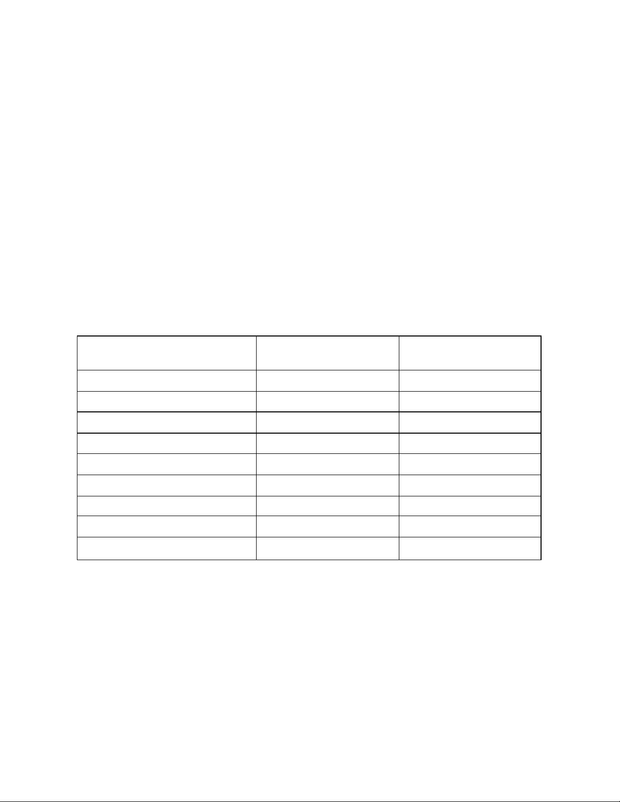
Table 1-1 Fryer Model Information
Specification Description SF14UFM SF14RUFM
Hourly Gas Input 110,000 BTUs (27,720 Kcal) 122,000 BTUs (30,744 KCal)
Number of Heat Tubes 4 4
Hourly French Fry Production 75 Lbs. (34.0 Kg) 102 Lbs. (46.3 Kgs.)
Minimum Fat Capacity 40-50 Lbs. (19.76 L) 42-50 Lbs. (20.5 L)
Frying Area 14" x 14" (35.6 cm x 35.6 cm) 14" x 14" (35.6 cm x 35.6 cm)
Frying Depth 4" (10.2 cm) 4" (10.2 cm)
Drain Valve Size 1-1/4" Full Port (3.175 cm) 1-1/4" Full Port (3.175 cm)
Shipping Weight 250 Lbs. (113.4 Kg) 275 Lbs. (124.7 Kg)
Gas Connection Size 1/2" (1.27 cm) 1/2" (1.27 cm)
1-1
1.2 CHECKING YOUR NEW FRYER
Your new fryer and its filter have been carefully packed into one crate. Every effort has been made to
ensure that your fryer will be delivered to you in perfect condition. As you unpack your new fryer, inspect
each of the pieces for damage. If something is damaged, DO NOT sign the bill of lading. Contact the
shipper immediately, the shipper is only responsible for 15 days after delivery. Check the packing list
enclosed with your fryer to ensure that you have received all of the parts to the fryer. If you are missing any
parts, contact the dealer from whom the fryer was purchased. As you unpack the fryer and it's accessories
be careful to keep the weight of the fryer evenly distributed.
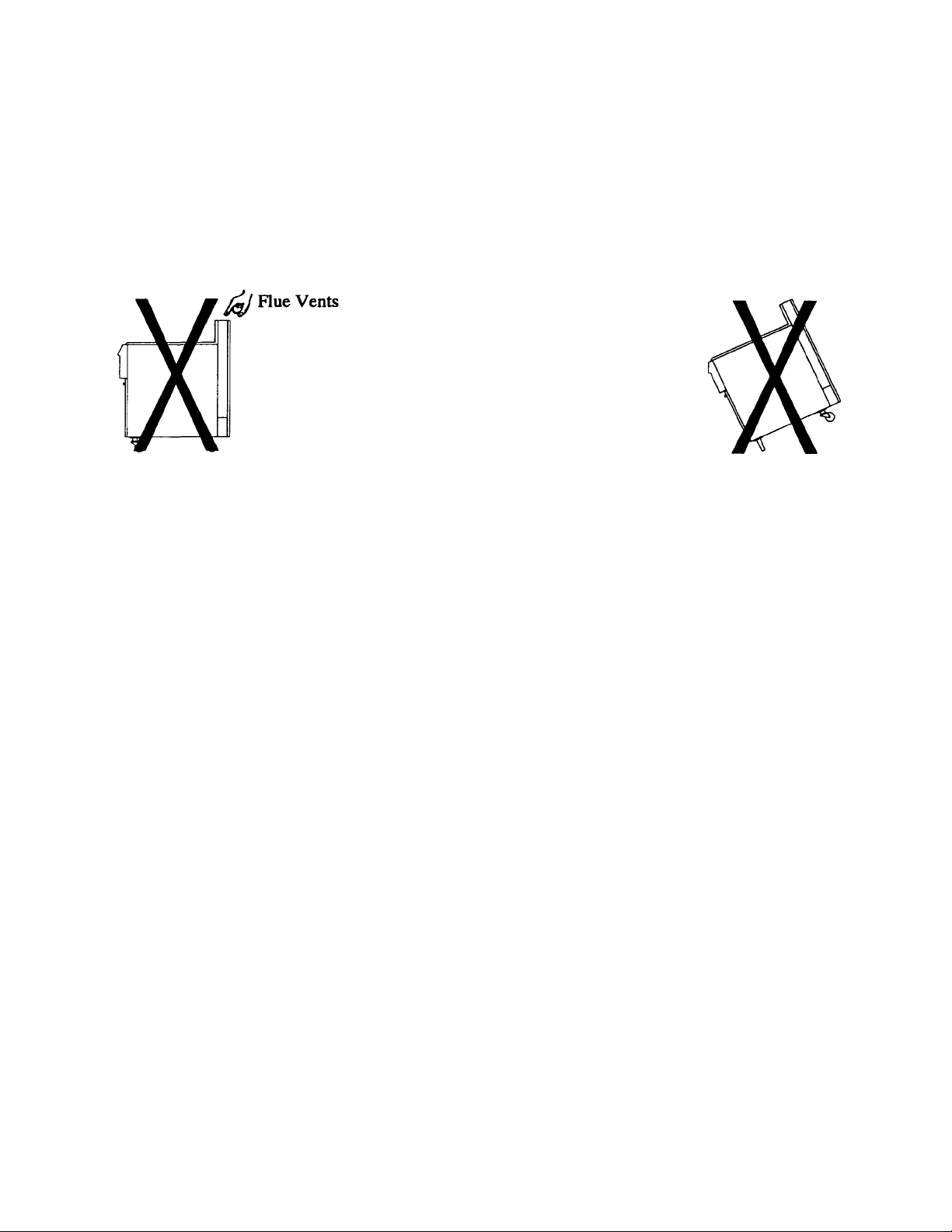
CAUTION
To prevent equipment damage, don't tilt the fryer onto
any two of its casters or pull the unit by the flue vents.
Locate your Pitco Frialator warranty and fill in the serial number of the fryer and the date received. You will
find the serial number on the plate inside the door. Put your warranty card in a safe place for future
reference. DO NOT return the card to Pitco Frialator.
1.2.1 Check Your Order
The crate containing the fryer unit will also contain the items listed below. These items are very important
and MUST be retained for future use. A complete description of each component is contained in the
Shortening Filter Procedure in Chapter 2.
(2) Fry baskets per fryer (1) Fry Basket Hanger per fryer
(2) Pitco Cleaner Sample (1) Drain Clean Out Rod
(1) Filter Crumb Catch (1) Precoat Filter Aid
(25) Filter Paper (1) Cleaning Brush (Fryer)
(1) Fryer Crumb Scoop (1) Filter Crumb Scoop
(1) Heat Deflector
1.3 ASSEMBLY AND LEVELING
When you receive your fryer it is completely assembled with the possible exception of the heat de flector.
1.3.1 Heat Deflector Installation
You will find a removable label at the rear top edge of the unit. This label has instructions for positioning
and installation of the heat deflector. Refer to the label and the instructions below to install the de flector.
1-2
a. Remove the two self -drilling screws from the top, back area of the cooker.
b. Position the heat deflector so that the angled portion of the deflector is facing toward the front
of the fryer. Secure the heat deflector to the back of the unit using the sheet metal screws
previously removed.
WARNING
DO NOT obstruct the flow of combustion/ventilation or air openings around the
fryer. Adequate clearance around the fryer is necessary for servicing and proper
burner operation. Ensure that you meet the minimum clearances specified in the
installation instructions.
c. When properly installed the angled section of the heat deflector will extend over the flue
opening to redirect the heat. It SHOULD NOT cover the flue opening. Nothing should block
the flue opening as this will cause the fryer to overheat and produce dangerous gases.
1.3.2 Leveling
Using an appropriate wrench and level ensure that the unit is level.
a. Place the level across the front of the tank and rotate the adjustment on the front legs to level
the unit.
b. Perform step a to level the unit front to back by placing the level along the side of the tank.
1.4 INSTALLATION
Although it is possible for you to install and set up your new fryer, it is STRONGLY recommended that
you have it done by qualified professionals. The professionals that install your new fryer will know the
local building codes and ensure that your installation is safe.
WARNING
The fryer must be properly restrained to prevent movement or tipping. This
restraint must prevent the fryer from movements that would splash hot liquids on
personnel. This restraint may be any means (alcove installation, adequate ties, or
battery installation).
1-3
1.4.1 Installation Clearances
The fryer needs clearance around it for proper operation. Adequate clearances allow for servicing and
proper burner operation. The clearances shown below are for cooker installation in combustible and noncombustible construction.
Combustible
Construction Construction
Back 6" 6"
Sides 6" 6"
Floor - Combustible N/A N/A
Non-Combustible
In addition to the clearances required for proper fryer operation, there must be at least 23 inches of aisle
space in front of the fryer to remove/install the filter pan.
1.4.2 Gas Connection
Your fryer will give you peak performance when the gas supply line is of sufficient size to provide the
correct gas flow. The gas line must be installed to meet the local building codes or National Fuel Gas
Code (NFPA 54-1984) and ANSI Z223.1-1988 Latest Edition. In Canada, install the fryer in accordance
with CAN/CGA-B149.1 or .2 and local codes. Gas line sizing requirements can be determined by your
local gas company by referring to National Fuel Gas Code, Appendix C, Table C-4 (natural gas) and
Table C-16 (propane). The gas line needs to be large enough to supply the necessary amount of fuel to all
appliances without losing pressure to any appliance. Other factors that are used to determine the piping
requirements are BTU requirements of the appliances being connected and the length of pipe between the
meter (main shut off) and the appliances.
WARNING
NEVER supply the fryer with a gas that is not indicated on the data plate. Using
the incorrect gas type will cause improper operation. If you need to convert the
fryer to another type of fuel, contact your dealer.
1.4.2.1 Fuel Types - Each fryer is equipped to work with one type of fuel. The type of fuel with which
the appliance is intended to operate is stamped on the data plate attached to the inside of the door.
WARNING
DO NOT use an open flame to check for gas leaks!
1-4

Input Voltage
120
VAC, 60Hz
220
(or
240)
VAC, 50Hz
1.4.2.2 Gas Line Connection - Connect the fryer to the gas supply line with a connector that complies
with the Standard for Connectors for Movable Gas Appliances (ANSI Z21.69-1987). If you are installing
a fryer with casters use a quick disconnect refer to the Quick Disconnect installation instruction, 1.4.2.3.
Connect the gas line to the fryer using a pipe joint sealant that is resistant to liquefied petroleum. If the
fryer was disconnected during the fuel line testing, use a solution of soap and water to leak test the new
connection.
NOTICE
NEVER use an adapter to make a smaller gas supply line fit the cooker connection.
This may not allow proper gas flow for optimum burner operation, resulting in
poor cooker performance.
1.4.2.3 Ouick Disconnect Gas Connection - Gas fryers
equipped with casters must be installed with connectors that
comply with the Standard for Connectors for Movable Gas
Appliances, ANSI Z21.69-1987, and Addenda Z21.69A -
1989. This connection should include a quick disconnect
device that complies with the Standard for Quick
Disconnect Devices for Use With Gas Fuel, ANSI Z21.41-
1989. When installing a quick disconnect you must also
install a means for limiting the movement of the fryer. This
device will prevent the gas line or the quick disconnect
from being strained. The restraining device should be
attached to the cooker on the back panel as shown in the
illustration. The quick disconnect, hose, and restraining
device can be obtained from your dealer.
1.4.2.4 Fuel Supply Line Leak and Pressure Testing - The fuel supply system must be tested before the
fryer is used. If the fuel line is going to be tested at a pressure greater than (>)1/2 PSIG (3.45 kPa), make
sure that the fryer is disconnected from the fuel line. If the fuel lin e is to be tested at a pressure equal to or
less than (≤) 1/2 PSIG (3.45 kPa), the fryer can be connected but the unit's gas valve must be shut. Test
all gas line connections for leaks with a solution of soap and water when pressure is applied.
1.4.3 Electrical Connection
The electrical service used by the fryer must comply with local codes. If there are no local codes that
apply, refer to the National Electrical Code (NEC) to install the service. In Canada refer to CSA Standard
C22.1 and local codes. Wirin g diagrams are provided inside the fryer door. The power requirements for
the fryer are shown below.
Current per fryer 7 Amps 3.5 Amps
1-5

WARNING
The fryer is equipped with an oil proof, three prong (grounding) plug for your
protection against electrical shock hazard in the event of equipment malfunc tion.
DO NOT cut or remove the grounding (third) prong from this plug. This plug must
be plugged into a properly grounded three prong receptacle.
The fryer has one power supply for the fryer controls and the filter module. The fryer must be grounded
in accordance with local code; if there is not a local code, comply with NEC ANSI/NFPA No. 70-1990.
The fryer should be plugged into a receptacle at all times to keep power supplied to the filter line heat
tape.
1.4.4 Ventilation and Fire Safety Systems
Your new fryer must have proper ventilation to function safely and properly. Exhaust gas temperatur es
can reach as high as 1200°F. Therefore, it is very important to install a fire safety system. Your
ventilation system should be designed to allow for easy cleaning. Frequent cleaning of the ventilation
system and the fryer will reduce the chances of fir e. Table 1-2 provides a list of reference documents that
provide guidance on ventilation and fire safety systems. This table is not necessarily complete.
Additional information can be obtained from the American Gas Association, 8501 East Pleasant Valley
Road, Cleveland, OH 44131.
Table 1-2. Ventilation and Fire Safety References
Topic
Grease Extractor ANSI/UL 710-1981 ANSI/NFPA 96-1987
Ventilation Hood ANSI/UL 705-1984 ANSI/NFPA 96-1987
Filter Unit ANSI/UL 586-1985 ANSI/NFPA 96-1987
Types of Fire Extingushers
and Detection Equipment
CO
ANSI/UL 154-1983 ANSI/NFPA 12-1989
2
Dry Chemical ANSI/UL 299-1984 ANSI/NFPA 17-1985
Water ANSI/UL 626-1984 ANSI/NFPA 13-1989
Foam
Sprinklers ANSI/UL 199-1982 ANSI/NFPA 13-1989
Smoke Detectors ANSI/UL 268-1981 ANSI/NFPA 72B-1986
Underwriters Laboratory
Document
ANSI/UL 900-1987
National Fuel Gas Code
Document
ANSI/NFPA 11-1988
ANSI/NFPA 13-1989
Fire Detection Thermostats ANSI/UL 521-1987 ANSI/NFPA 72B-1986
1-6

Excessive ventilation causes drafts, which will interfere with the proper operation of the pilot and the
burner. Leave at least 18 inches of open space between the fryer's flue vent opening and the intake of the
exhaust hood.
CAUTION
Ensure that your ventilation system does not cause a down draft at the fryer's flue
opening. Down drafts will not allow the fryer to exhaust properly and will cause
overheating which may cause permanent damage. Damage caused by down drafts
will not be covered under equipment warranty. NEVER allow anything to obstruct
the flow of combustibles or ventilation exiting from the fryer flue. DO NOT put
anything on top of the flue area.
NOTICE
NEVER connect the blower directly to the flue openings. The direct flow of air will
cause poor temperature recovery, poor ignition, inefficient operation of the fryer,
and could extinguish the pilot.
1.5 INITIAL ADJUSTMENTS
After your fryer has been installed as described in section 1.4, it needs to be adjusted to ensure that it will
perform as designed. These adjustments must be performed by a qualified person. To perform these
adjustment the following tools will be needed:
• Manometer (low pressure gauge) • Digital Thermometer (Temperature probe)
• DC Millivolt Meter
1.5.1 Visual Checks
Before you begin filling and adjusting the fryer, perform the following visual
checks:
a. After the fryer is in its permanent location, check for levelness. Any
additional leveling that is necessary can be performed as described in
section 1.3.
b. Check the temperature bulbs (thermostat/high-limit), located in the
fryer tank to ensure that the mounting screws are tight. The figure
shows the probe typical location. Look down inside the fryer tanks to
see the probes.
1-7

1.5.2 Burner Ignition Systems
CAUTION
Before going any further, fill the fryer with WATER. Water is used for the
installation adjustments because the temperature will never exceed 212°F (100°C)
thereby allowing plenty of adjustment time. Never let the water level go below the
OIL LEVEL mark on the rear of the tank.
WARNING
There is an open flame inside the fryer. The unit may get hot enough to set near by
materials on fire. Keep the area around the fryer free from combustibles.
1.5.2.1 Lighting Instructions for Manual Pilot Lights - To light the pilot light refer to these instructions
and Figure 1-1. The numbers in parenthesis refer to Figure 1-1 callouts.
WARNING
Wait 5 minutes before attempting to relight the pilot to allow for any gas in the fryer
to dissipate.
a. Open the gas supply valves to the fryer.
b. Open the fryer's door to gain access to the controls. Turn the thermostat control knob (1)
counterclockwise to the off position.
c. Turn the Unitrol gas valve knob (tan knob) (2) to the PILOT position and push
in on the knob. Hold the knob in for approximately one minute to purge the
air out of the line. Hold a flame to the pilot light until the pilot (3) ignites.
This may take a little while the first time you light the fryer because of air in
the lines. Once lit, hold the knob in for approximately 60 seconds and then release.
d. If the pilot goes out wait 5 minutes and repeat step c. If after three tries the pilot will not remain
lit, refer to the operator troubleshooting section of this manual.
e. Turn the Unitrol gas valve knob (tan knob) counterclockwise to the ON
position.
f. Set the thermostat control knob to the desired temperature setting.
1-8

g. The main burner (4) will light and be controlled by the thermostat. The pilot burner will remain
lit regardless of the switch position.
Figure 1-1 Inside View of Fryer
1.5.2.1.1 Pilot Flame Adjustment - The pilot flame should be adjusted to produce the proper millivolt
output from the pilot sensing device. Millivolt output for the thermopile should be between 300 and 500
millivolts. Figure 1-2 shows the pilot assembly with examples of the incorrect and correct pilot size.
Example A illustrates a pilot flame size that is too small to produce sufficient millivolt output. Example
B is the correct size for proper millivolt output.
Figure 1-2 Pilot Assembly, Flame Adjustment
1-9

a. This test requires a DC millivolt meter set to a scale of 0-l000mv.
b. Locate the thermopile wires coming from the thermostat/High Limit box going to the gas shut
off valve. The wire insulation size decreases near the gas valve connections.
c. Connect the negative (-) test probe to pilot bracket.
d. Connect the positive (+) test probe to one of the High Limit terminal connections
e. Remove the pilot flame adjustment cover.
Figure 1-3 Gas Valve Showing Location of the Pressure Regulator and Pilot Adjusters
f. Turning the flame adjusting screw clockwise lowers the flame and the millivolt output. Turning
the screw counterclockwise increases flame size and millivolt output.
g. Rotate the screw in the direction to achieve a reading of 400 ±50 mv for thermopiles.
NOTICE
Allow 3 to 5 minutes between flame adjustments to allow the reading to settle.
h. Replace the pilot flame adjusting screw cover.
1-10

1.5.3 Main Burner System
For the burners to work the gas supply valve must be open and the main power switch must be on. The
main burner receives gas from the main gas supply through the thermostatically controlled valve. When
the thermostat is turned up the gas control valve opens and the pilot will ignite the burners. After the
burner system is operating, perform the burner adjustments in the following procedure. Figure 1-5
illustrates the different conditions possible for the main burner.
The tubes and baffles are
badly carbonized. Check vent
and adjust if necessary. Check
for heat tube or flue blockage.
INSUFFICIENT FLOW
Have gas company check
incoming gas pressure. Adjust
manifold pressure as described
in 1.5.3.2.
The flame seems to "lift off the
face of the burner. To correct
adjust main burner as described
in . 1.5.3.2.
EXCESSIVE FLOW
A soft, steady blue flame
should enter the heat tube
without touching the front
outside rim of the tube.
INSUFFICIENT GAS PRESSURE
NORMAL FLOW
Figure 1-4 Main Burner Conditions
1-11

1.5.3.1 Gas Line Requirements - A properly installed gas supply system will deliver 7.0 ±2.0" w.c.
natural gas (12.0 ±2.0" w.c. LP) to all appliances connected to the line, operating at full demand.
1.5.3.2 Burner Adjustment - The burners must be adjusted to deliver optimum flame. Adjust the burner
flame using the following procedure.
a. Ensure that the gas control valve is in the OFF position. Remove the manifold pressure tap
plug and connect an accurate pressure gauge (range of 0-16" w.c. in 0.1" increments) or
manometer.
b. Light the pilot burner (see 1.5.2) for the unit being tested and adjust the thermostat to light
the main burners.
c. The installed pressure gauge reading should be the same, ±0.1", as that marked on the data
plate inside the door. If the pressure is correct go to step e, if not, adjust the pressure.
d. To adjust the pressure, remove the regulator adjustment screw cover (see Figure 1-3). Use a
flat tip screwdriver to adjust the screw until the proper pressure is reached. Turning the screw
clockwise will increase the pressure, counterclockwise will decrease the pressure.
e. When the pressure is correct, install the regulator adjustment screw cover.
f. To remove the pressure gauge, turn gas control valve to OFF. Remove the gauge and install
the pressure tap plug.
Figure 1-5 Air Collar
1-12

g. Now that the pressure is set for proper operation, set the main burner flame. Unlock the air
collars by loosening the set screw for the collars. Turn the gas control valve to ON and turn
thermostat to light the main burners.
h. Adjust the shape and size by raising or lowering the air collars to achieve a soft blue flame
with well defined inner cones.
i. When the flames have been properly adjusted, lock the collars in place with the set screw
provided.
1.5.4 INITIAL CLEANING
When the fryer is shippe d, many of its parts are covered with a thin coat of oil for protection. Before the
fryer is ready for cooking it must be cleaned. This will remove the oil coating and any foreign matter that
may have accumulated during storage and shipment. Perform the cleaning as described below.
a. Fill the tank with water and add one packet of Pitco fryer cleaner or a mild detergent.
b. Turn the fryer on and set the thermostat to 200°F. Allow the fryer to heat for 15 minutes.
NOTICE
Do not leave the fryer unattended during cleaning. Never let the water level go below
the "OIL LEVEL" mark on the back of the tank.
c. Using the fryer cleaning brush, scrub the inside of the fryer to remove protective coating.
d. When cleaning is complete, turn off the fryer main burners and turn gas valve knob to the
PILOT position. If the fryer has electronic ignition turn the gas control valve to the OFF
position. Drain the water into a container suitable for hot water and dispose of it.
e. When the tank has cooled, rinse it thor oughly with cool water. Continue to rinse the tank until
the cleaner has been rinsed, thoroughly from the tank.
f. Using a clean dry cloth, wipe out all of the water. Be very thorough removing the water,
because any residual water will cause hot oil to splatter out of the fryer.
CAUTION
Mild steel tanks must be wiped down/coated with oil to keep the tank from rusting.
g. Now that the tank is clean, you are ready to fill and operate the fryer. Refer to 2.1 for
instructions on adding shortening to the fryer.
1-13

1.5.5 Thermostat Calibration Check
NOTICE
Thermostat calibration requires that the temperature of the fryer be raised above
boiling. Therefore, you will need to drain the water from the fryer and fill it with
oil. Before removing the water, perform the initial cleaning of the fryer. Cleaning
the fryer now will prevent you from having to drain the oil and refill with water
later.
Filling the fryer with oil is described in 2.1. To perform the calibration check detailed below you will
need a digital thermometer.
a. Place the tip of the thermometer in the shortening approximately 1" above the temperature
sensors.
b. Set the thermostat at 325°F and wait for the temperature reading on the thermometer to rise. As
the temperature rises toward 325°F watch the thermometer closely.
c. If the shortening temperature reaches 350°F and the burners DO NOT turn off, turn the
thermostat down. Keep lowering the thermostat setting until the burners go out.
CAUTION
If the burners do not turn off at the lowest thermostat setting, the thermostat could be
defective. Contact your ASAP representative.
d. Let the fryer cycle 4 to 6 times before checking the temperature. Compare the thermometer
temperature against the thermostat setting. If the values are more than 5°F apart, calib rate the
thermostat using the appropriate calibration procedure in this manual.
1.5.6 Thermostat Calibration
To calibrate the thermostat the dial must be removed from the shaft. The adjustment for the thermostat is
inside the dial shaft.
a. Place the tip of the thermometer in the shortening approximately 1" above the temperature
sensors.
b. Set the Thermostat to 325°F and wait for the temperature reading on the thermometer to rise.
c. Let the fryer cycle 4 to 6 times to ensure that the temperature has stabilized. Compare the
thermometer temperature against the thermostat setting. If the values are more than 5°F apart,
calibrate the thermostat using the following procedure.
1-14

d. Set the thermostat dial to 325°F.
e. Remove the thermometer dial by pulling the knob straight out. DO NOT rotate the dial.
f. Hold the outside of the shaft so it does not move. Use the tip of a small, flat tip screw driver to
scrape away the sealing compound from the adjustment screw.
g. Turn the adjustment screw clockwise to lower the temperature setting and counterclock-wise
to raise the temperature. One quarter turn changes the temperature approximately 25°F.
h. Turn the adjustment until the burners turn on at 325°F. Replace the knob and allow the fryer to
cycle 4 to 6 times. Check the temperature of the thermometer against the thermostat dial, if it
is greater than 5°F difference repeat the calibration procedure.
i. When the calibration is correct, remove the thermometer and replace the tube screen.
1.5.7 High Limit Test
THIS TEST SHOULD BE PERFORMED BY QUALIFIED PERSONNEL ONLY
1-15

Chapter 2: Operating Instructions
This chapter describes how to operate your fryer to obtain the best performance. Included in this chapter
are filling, operating, and cleaning instructions for gas fryers.
2.1 FILLING THE FRYER
Both liquid and solid shortening can be used in the fryer. If solid shortening is used, it is recommended
that you use the melt cycle feature (optional) to melt the shortening. You can melt solid shortening
without the melt option, but you must carefully follow the instruction in section 2.2.2.
2.1.1 Filling the Fryer With Liquid Shortening
a. Make sure the drain valve is completely closed.
b. Fill the fryer with oil to the "Oil Level" line marked on the back
of the tank.
2.1.2 Filling the Fryer With Solid Shortening
WARNING
Never melt blocks of solid shortening on top of the burner
tubes. This will cause a fire, and will void your warranty.
a. Make sure the drain valve is completely closed.
b. Remove the screen covering the tubes.
c. Cut the shortening into cubes no larger than 1". ALWAYS
pack the shortening below, between, and on top of the burner
tubes. DO NOT leave any large air gaps. Use care when
packing the solid shortening in the tank. DO NOT bend or
break the temperature sensor probes. If these are damaged the
fryer will not function properly.
d. Once the fryer is packed with shortening, the shortening must be melted. To melt the
shortening refer to the Fryer Start-Up section for your fryer.
2-1

2.2 MELTING SOLID SHORTENING
The melting procedure below requires the manual cycling of the fryer. Watch
carefully for smoke. If smoke is noticed, the shortening is scorching. To prevent
this, decrease the time you leave the burners on.
a. Rotate the thermostat to cause the main burners to light and remain lit for 4 seconds.
b. Rotate the thermostat back to off for 30 seconds.
c. Continue cycling the main burners until most of the solid shortening is liquefied and the
temperature reaches 150°F. At 150°F leave the thermostat set at the desired temperature. The
burners will remain on constantly until the shortening temperature reaches the thermostat
setting.
d. Once at temperature, the fryer is now operating normally and ready to use.
23 OPERATING INSTRUCTIONS
NOTICE
To ensure the food always comes out the very best, follow the preparation instructions for the food you
are cooking. Using the best shortening makes the best fried foods. The best shortening will last longer
than lower grade shortening and save you money. When not in use the shortening should be cooled and
covered to prevent contamination.
CAUTION
The fryer has been installed using restraining devices to prevent accidental tipping
or movement. Do not attempt to move the fryer when it has hot liquid in it.
Splashing hot liquids can cause severe bums.
WARNING
Water and shortening DO NOT mix. Keep liquids away from hot shortening.
Dropping liquid frozen food into the hot shortening will cause violent boiling.
2.3.1 Fryer Start -Up
DO NOT START FRYER WITHOUT FILLING WITH OIL!
a. Light the pilot light as described in section 1.5.2.
2-2

b. Turn the temperature control knob (thermostat) to the desired temperature setting. This knob is
located behind the front doors or on the front control panel.
c. The main burners will light and cycle at the thermostat setting.
2.3.2 Fryer Shut-Down
There are two shutdown modes of fryer operation, STANDBY and COMPLETE. The standby mode
removes the ability for the fryer's main burners to cycle. Complete shutdown turns off the gas supply to
the fryer. Shut down the fryer by:
STANDBY Turn the thermostat to OFF. Depress and turn the gas valve clockwise to
the PILOT position (if fryer has an electronic ignition turn the gas valve
to the Off position). The fryer is now in Standby and can remain this way
for only brief periods of time. NEVER leave the cooker in standby
overnight.
COMPLETE To completely shut down the cooker, turn the gas valve counterclock-wise
to the OFF position and turn the power switch off (if used). The fryer is
now completely shut down and can be cleaned and filtered.
2.3.3 Power Failure
If power is removed from the fryer during filtering, place the filter switch in the OFF position and close
the return valve. When power is restored restart the filter procedure
2-3

2.4 SHORTENING FILTER PROCEDURES
This section describes the procedures used to filter fryers using the solo filter unit. Figure 2-1 shows the
locations of the components used in the filter process. The filter accessories and tools you should have to
perform normal filtering operations are described on page 2-5. Frequent filtering of your shortening will
prolong the shortening's usable life. Daily shortening filtering is strongly recommended.
NOTE
See Maintenance Section for Filter
Operational Information.
Figure 2-1 Fryer Illustrating Filter Components
2-4

Return Valve RED - When open, with the filter
pump on, allows the shortening to return to the
fryer tank.
Filter Crumb Scoop - Short handle wide pan
design, this scoop is used to remove the debris from
the filter pan.
Drain Valve BLACK- Drain the oil from the
fryer tanks to the filter pan.
Oil Return Connection - Disconnect for return
oil from the filter unit to the fryer. Simply push
to left on fitting to connect. Pull to right to
disconnect.
Filter Unit Cord - Provides electrical power to
the filter unit.
Filter Paper - Package of pre-cut filter paper.
Filter Crumb Catch -Mounts in the filter pan lid
and catches large debris during filtering.
Flush Hose (OPTIONAL) - Attached to the
filter piping, this hose and nozzle is used to flush
out the fryer tank. This hose is an optional item.
Cleaner - Used during fryer boil-out cleaning.
Drain Clean Out Rod - Long handled design, this
tool is used to clean out the drain openings.
Precoat Filter Aid - Coarse Diatomaceous earth
used to enhance the filter ability of the filter media.
Cleaning Brush -This long handled stiff bristle
brush is used to brush down the crumbs inside the
fryer tank during shortening filtering.
Fryer Crumb Scoop -A specially designed long
handle scoop for scooping out the fryer. The scoop
section is narrow enough to fit down be tween the
fryer burner tubes.
At operating temperature the shortening temperature may be greater than 300°F.
Extreme care should be used when filtering operating temperature shortening to
avoid personal injury.
2.4.1 General Filter Hints
1. Ensure that all oil in the filter pan is returned before it cools and hardens. This is very
important if you are using solid shortening.
2. Always use Pitco Precoat® for fastest filtrations, maximum labor saving, and cleanest/
clearest shortening possible. Impaired filter performance will result without the use of a filter
aid.
3. The longevity of your oil is related to how clean you keep it. With a Pitco solo filter system,
it is easy to do a quick drain/refill anytime. By removing suspended particles often, it
prevents them from burning.
WARNING
2-5

4. When the time it takes to refill the fryer after filtering exceeds 3:00 minutes, scrape the filter
bag or paper. If scraping does not bring the refill time back down change the filter paper as
described in 3.1.
5. The filter pump is protected from clogging by a special screen in the pickup tube. Clean
this screen each time a new filter is installed (see Chapter 3,3.4.2)
6. If you have filter system problems refer to section 3.4.2.
7. Purge the filter lines by allowing the filter pump to run 15 seconds after air bubbles are seen
inside the fryer tank.
2.4.2 Filter Procedures: Numbers in parenthesis refer to Figures 2-1 and 2-2.
NOTICE
• When working with hot oil ALWAYS wear oil-proof, insulated gloves.
NEVER
• Run the filter system without a filter bag/paper.
• Attempt to filter more than one fryer tank at a time.
• Empty the oil from the fryer before turning OFF the fryer burners.
• Store the UFM Filter Unit anywhere other than in the fryer filter cavity.
a. Disconnect the filter pan, slide it out and empty the crumb basket. Scrape previously filtered
residue off the filter paper. Examine the filter bag for dark, scuffed, or torn areas. Refer to
3.1.1 for filter bag replacement instructions. Re-install the pan.
b. Turn the fryer OFF (See Standby Shutdown, section 2.3.2).
Remove the baskets from the fryer tank(s). Use the clean out rod
to lift out the tube screens. If there are excess crumbs in the fryer
tank, remove them with the crumb scoop.
c. If you have replaced or scraped the filter paper, stir in Precoat
Filter Aid to the shortening in fryer (8 oz. by volume). After
cleaning out the excess debris with the fryer scoop sprinkle the
powder into the first fryer to be filtered and stir the powder into
the oil.
NOTICE
Always open a system valve before starting the filter pump.
2-6

d. Slowly open the drain valve by using the black knobbed extension rod. If necessary use the
clean-out rod to clear the crumbs from the drain. Use the long handled brush to clean the sides
of the tank as the oil drains.
e. Open the red handled return valve to the tank you are filtering. When the tank is empty close
the drain valve and turn on the filter pump. As the tank fills, brush the inside of the tank to
remove crumbs.
f. When bubbles are seen coming out of the oil return spout, turn off the pump. Open the drain
valve and allow the tank to drain again. Repeat steps b through d until the tank is clean.
g. When cleaning is complete, turn the pump off, close the drain valve, and replace the tube
screen. Open the red handled return valve and turn on the pump to refill the fryer with the
filtered oil. Continue to run the filter pump until bubbles come out the oil return opening.
Turn the pump off and close the red handled return valve. If necessary add more shortening to
the tank to return the shortenin g level to the fill mark. The fryer is now ready for use.
2.5 DAILY CLEANING
Your fryer should be cleaned every day to maintain peak performance and appearance. Perform the
procedures below every day.
a. Wipe up any shortening that spills onto the exterior of the fryer. This should be done with a
clean soft cloth.
b. Use warm water with a mild detergent to clean surfaces. Be careful not to get water in the
shortening. Rinse completely and dry thoroughly before use.
c. Use a non-abrasive scouring powder or pad to clean stains if necessary.
d. Perform the weekly boil out cleaning of your fryer described in section 3.2.
2-7

Chapter 3: Owner Maintenance and Adjustments
This chapter provides you with the information and procedures necessary to perform basic fryer
maintenance and adjustments. If after performing maintenance on your fryer it does not perform
properly, contact your authorized service center.
WARNING
The power supply must be disconnected before servicing or cleaning the appliance.
3.1 FILTER MEDIA REPLACEMENT
This section describes the filter system's components and details the procedures necessary to replace the
filter media.
WARNING
At operating temperature, the shortening in the fryer may be hotter than 375°F
(190°C). This hot, melted shortening will cause severe bums. Do not let the hot
shortening touch your skin or clothing. Always wear insulated oil-proof gloves
when working on the filter system.
The filter module stores neatly under the fryer. The unit is very easy to use and allows for quick
installation and filtration, even under the busiest conditions. The filter module is shown in Figure 3-1
with specific components and features pointed out and briefly described.
Follow the procedures below to change the filter paper.
WARNING
It will be easier and safer if the filter assembly has cooled to room temperature
before handling any filter parts.
a. To remove the filter pan, disconnect the filter tube connection. This is done by sliding the
insulated portion of the connector out of the receiving portion of the connector.
b. Grasp the filter pan and gently pull the assembly out the front of the fryer, remove the filter pan
lid.
c. Remove the crumb catch tray from the top of the filter pan. Discard any debris that may be in
the crumb catch.
3-1

Figure 3-1 Filter Module
(1) Filter Pan - Holds the oil from the fry tank.
(2) Pick-Up Tube - Connects filter envelope
assembly to piping. Incorporates a strainer to
protect filter pump from grit in the event of
envelope failure.
(3) Filter Assembly Connector - An insulated
handle covers the filter pan assembly connection.
This connection separates the filter pick-up assembly from the filter piping for removing the filter
pan for cleaning.
(4) Filter Media Connector - Connects the filter
pick -up tube to the filter media rack. An internal
screen keeps debris out of the filter pump.
(5) Flexible Coupling - Flexible coupling allows
for easy movement when connecting and disconnecting the pickup tube from the fryer.
(6) Casters - Allows for easy movement of the
pan.
3-2

d. Lift up on the filter paper assembly and remove from the filter pan. Unscrew the suction tube
from the filter paper support rack. Remove the clip screen and slide the filter paper support
rack assembly out of the filter bag.
e. All of the filter pick up assembly parts
can be washed in a dish washer or a pot
sink. Flush out the suction tube assembly
with hot water. The pick up tube screen
keeps grit and solid material from
binding the pump. After flushing the
pick up tube screen check to ensure that
the screen is free of debris. After
cleaning, it is very important to
thoroughly dry the parts before reassembling. Water and oil do not mix.
Water in hot oil will cause the oil to
splatter.
f. Start re-assembling the filter pick up
assembly by sliding the new filter paper
on to the filter paper support rack.
Ensure that the hole in the filter paper
goes over the pick up tube assembly
threaded connector.
g. Fold the open end of the bag in two
folds. The first fold should be
approximately 1 inch from the end and
the second should be over the edge of
the rack assembly.
h. Slide the clip screen over the folded end
of the filter paper. Ensure the opening of
the clip screen goes over the pick up tube connection. Screw the suction tube assembly onto
the threaded connection.
i. Place the filter rack assembly in the filter pan and install the crumb catch tray in the top of the
filter pan lid. Place lid on filter pan.
j. Slide the filter pan assembly back into the fryer and attach the pick up tube connector to the
filter unit connection.
3-3

3.2 WEEKLY FRYER CLEANING (BOIL OUT)
The fryer should be thoroughly cleaned once a week. This cleaning should include a complete draining of
the fryer and a boil out. This would also be a good time to replace the filter paper if necessary.
a. You will ne ed a container large enough to hold the volume of the tank. This container should
also be able to withstand boiling water temperatures.
CAUTION
Completely shut down the fryer when the oil is to be replaced by water, and when
the heating portion of the cleaning is complete. This will prevent the heating
system from coming on during the oil draining and water filling procedure.
b. Drain the oil from the fryer and discard or save for reuse. Remove tube rack/mesh tube screens
and remove any large debris from the bottom of the fry tank. Once clean, return tube
rack/mesh screens to the fry tank. Close the drain valve and fill the fry tank with water and
noncaustic detergent. For best results use Pitco Fryer Cleaner.
c. Restart your fryer as described in 2.3 and set the thermostat to 200°F and bring the water to a
slow boil. DO NOT allow water to boil because excessive foaming will occur. Once the water
is at a slow boil turn off the fryer.
d. Allow the fryer to soak for 20 minutes to soften shortening deposits and carbon. Use fryer
brush to remove any residue from tank, heating tubes, and side walls. Perform the daily
cleaning procedure described in section 2.5.
e. Remove the filter unit from under the fryer. Slide a container to catch the water under the fryer
so that the pipe that is normally aimed into the filter pan is aimed into the container and open
the drain valve.
f. Drain the hot water to the container and rinse the tank with clean warm water.
g. Wipe the tank dry with clean cloth wipes. Close the drain valve and remove the large container.
h. Refer to section 2.1 to refill the fryer.
3.3 FLUE INSPECTION
It is recommended that once every six months, with the cooker cooled down, you examine the flue area.
Check for corrosion or blockage of the flue. Ensure that the cooker is shutdown and do not turn it on
during the examination. Examination of the flue area during cooking may cause bodily injury.
3-4

3.4 TROUBLESHOOTING
This section is provided to aid you in the event of fryer or filter troubles. If these troubleshooting
procedures do not correct your problem contact a qualified technician or the factory. The troubleshooting
procedures are in a flowcha rt format.
3.4.1 Fryer Troubleshooting
Refer to this section to correct common problems that may be encountered in equipment operation.
3-5

3.4.2 Filter Troubleshooting
Refer to this section to correct common problems that may be encountered during filter operation.
3-6

3-7
 Loading...