

Page 1
IMPORTANT FOR FUTURE REFERENCE
Please complete this information and retain this manual
for the life of the equipment:
Model #: ___________________________
Serial #: ___________________________
Date Purchased: ____________________
Installation & Operation Manual
SG6H: Solstice Gas Fryer
SFSG6H: Solstice Gas Fryer with Filter
Built after 3/2009
ENGLISH
SFSG6H Shown
I
S
G
E
N
D
C
E
E
R
I
T
F
I
CIRET IFED
D
L20-332, rev. 1 (05/11)
Page 2

TO THE PURCHASER, OWNER AND STORE MANAGER
Please review these warnings prior to posting them in a prominent location for reference.
TO THE PURCHASER
Post in a prominent location the instructions to be followed
in the event that an operator smells gas. Obtain this
information from your local gas supplier.
WARNING
DO NOT store or use gasoline or other flammable vapors and
liquids in the vicinity of this or any other appliance.
WARNING
Improper installation, alteration, service or maintenance can
cause property damage, injury or death. Read the
installation, operating and maintenance instructions
thoroughly before installing or servicing this appliance.
WARNING
Installation, maintenance and repairs should be performe d
by a Pitco Authorized Service and Parts (ASAP) company
technician or other qualified personnel. Installation,
maintenance or repairs by an unauthorized and unqualified
personnel will void the warranty.
WARNING
Installation and all connections must be made according to
national and local regulations and codes in force.
WARNING
During the warranty period if a customer elects to use a nonoriginal part or modifies an original part purchased from
Pitco and/or its Authorized Service and Parts (ASAP)
companies, this warranty will be void. In addition, Pitco and
its affiliates will not be liable for any claims, damages or
expenses incurred by the customer which arises directly or
indirectly, in whole or in part, due to the installation of any
modified part and/or received from an unauthorized ser vice
center.
WARNING
This appliance, when installed, must be electrically grounded
in accordance with local codes, or in the absence of local
codes, with the National Electrical Code, ANSI/NFPA 70, or
the Canadian Electrical Code, CSA C22.2, as applicable.
WARNING
Adequate means must be provided to LIMIT the movement or
this appliance without depending on the gas or electrical
cord connection. Single appliances equipped with legs must
be stabilized by installing anchor straps. All appliances
equipped with casters must be stabilized by installing
restraining chains.
WARNING
An appliance equipped with casters and a flexible gas line
must be connected to the gas supply with a quick disconnect
device. This quick disconnect must comply with ANSI Z24.41.
WARNING
DO NOT alter or remove structural material on the appliance
to accommodate placement under a ventilation hood.
WARNING
This appliance is intended for professional use only and
should be operated by fully trained and qualified personnel.
WARNING
If the appliance is equipped with a power cord and it is
damaged, it must be replaced by a Pitco Authorized Service
and Parts (ASAP) company technician, or a similarly
qualified person in order to avoid a hazard.
WARNING
The power supply must be disconnected before servicing,
maintaining or cleaning this appliance.
WARNING
The appliance is NOT jet stream approved. DO NOT clean
the appliance with a water jet.
WARNING
DO NOT attempt to move this appliance or transfer hot
liquids from one container to another when the unit is at
operating temperature or filled with hot liquids. Serious
personal injury could result if skin comes in contact with the
hot surfaces or liquids.
WARNING
DO NOT sit or stand on this appliance. The appliance’s front
panel, tank, splash back, tank cover, workshelf, drain board
is not a step. Serious injury could result from slipping,
falling or contact with hot liquids.
WARNING
NEVER use the appliance as a step for cleaning or accessing
the ventilation hood. Serious injury could result from slips,
trips or from contacting hot liquids.
WARNING
The oil/shortening level should NOT fall below the minimum
indicated level line at any time. The use of old shortening
can be dangerous as it will have a reduced flash point and be
more prone to surge boiling.
WARNING
The contents of the crumb catch and/or filter pan of any filter
system must be emptied into a fireproof container at the end
of each day. Some food particles can spontaneously
combust if left soaking in certain types of oil or shortening.
WARNING
Completely shut the appliance down when shortening/oil is
being drained from the appliance. This will prevent the
appliance from heating up during the draining and filling
process. Serious injury can occur.
WARNING
This appliance is intended for indoor use only.
WARNING
DO NOT operate appliance unless all panels and access
covers are attached correctly.
WARNING
It is recommended that this appliance be inspected by a
qualified service technician for proper performance and
operation on a yearly basis.
WARNING
There is an open flame inside this appliance. The unit may
get hot enough to set nearby materials on fire. Keep the area
around the appliance free from combustibles.
WARNING
DO NOT supply the appliance with a gas that is not indicated
on the data plate. If you need to convert the appliance to
another type of fuel, contact your dealer.
WARNING
DO NOT use an open flame to check for gas leaks!
WARNING
If gas flow to appliance is interrupted, or pilots extinguish,
wait 5 minutes before attempting to relight the pilot to allow
any residual gas in appliance to dissipate.
WARNING
Ensure that the appliance can get enough air to keep the
flame burning correctly. If the flame is starved for air, it can
give off a dangerous carbon monoxide gas. Carbon
monoxide is a clear odorless gas that can cause suffocation.
ii L20-332, rev.1 (05/11)
Page 3

MODEL SG6H FRYER TABLE OF CONTENTS
1. INSTALLATION......................................................................................2
1.1. CHECKING YOUR NEW APPLIANCE..........................................................................................2
1.2. INSTALLATION CLEARANCES...................................................................................................3
1.3. LEG/CASTER INSTALLATION AND LEVELING.........................................................................3
1.4. GAS CONNECTION.......................................................................................................................4
1.4.1. QUICK DISCONNECT CONNECTION...................................................................................4
1.4.2. FUEL SUPPLY LINE LEAK AND PRESSURE TESTING ......................................................4
1.4.3. CE GAS TABLE (NOT APPLICABLE TO ALL MODELS) ......................................................5
1.5. ELECTRICAL CONNECTIONS.....................................................................................................6
1.6. VENTILATION AND FIRE SAFETY SYSTEMS............................................................................7
INSPECTION.............................................................................................................................................7
1.8. INITIAL ADJUSTMENTS...............................................................................................................8
1.8.1. FILLING THE APPLIANCE .....................................................................................................8
1.8.2. LIGHTING INSTRUCTIONS ...................................................................................................8
1.8.3. PILOT FLAME ADJUSTMENT................................................................................................9
1.8.4. MAIN BURNER SYSTEM ADJUSTMENT............................................................................10
1.9. INITIAL CLEANING .....................................................................................................................11
2. OPERATION.........................................................................................12
2.1. OPERATIONAL FEATURES.......................................................................................................12
2.1.1. BASIC OPERATIONAL FEATURES.....................................................................................13
2.1.2. OPERATION FEATURES SPECIFIC TO MODELS WITH FILTERS...................................13
2.2. FILLING THE COOKER TANK....................................................................................................14
2.2.1. FILLING THE TANK WITH LIQUID SHORTENING..............................................................14
2.2.2. FILLING THE TANK WITH SOLID SHORTENING...............................................................14
2.3. APPLIANCE START UP..............................................................................................................15
2.4. COOKING.....................................................................................................................................16
2.4.1. TIMER OPERATION.............................................................................................................16
2.4.2. ADDITIONAL CONTROLLER FUNCTIONS.........................................................................16
L20-332, rev. 1 (05/11) iii
Page 4

TABLE OF CONTENTS
2.5. COOKING TIPS............................................................................................................................16
2.6. APPLIANCE SHUTDOWN...........................................................................................................17
2.6.1. STANDBY MODE..................................................................................................................17
COMPLETE SHUTDOWN...................................................................................................................17
3. PREVENTATIVE MAINTENANCE.......................................................18
3.1. DAILY PREVENTATIVE MAINTENANCE ..................................................................................18
3.1.1. FILTERING WITH A FILTER DRAWER (IF EQUIPPED)....................................................18
3.1.2. FLUSH HOSE OPERATION (IF EQUIPPED).......................................................................18
3.1.3. REPLACING THE FILTER MEDIA (IF EQUIPPED).............................................................19
3.1.4. APPLIANCE INSPECTION...................................................................................................19
3.1.5. CLEANING THE COOK TANK..............................................................................................20
3.1.6. CLEANING THE CABINET...................................................................................................20
3.1.7. FILTER CLEANING (IF EQUIPPED) ....................................................................................20
3.2. WEEKLY PREVENTATIVE MAINTENANCE..............................................................................20
3.3. MONTHLY PREVENTATIVE MAINTENANCE ...........................................................................21
3.3.1. BOIL OUT PROCEDURE......................................................................................................21
3.3.2. TEMPERATURE CHECK......................................................................................................22
3.4. ANNUAL/PERIODIC PREVENTATIVE MAINTENANCE AND INSPECTION............................22
3.4.1. SAFETY EVALUATION.........................................................................................................22
3.4.2. MECHANICAL INSPECTION................................................................................................22
3.4.3. TEMPERATURE CONTROL SYSTEM.................................................................................22
3.4.4. FILTER SYSTEM (IF EQUIPPED)........................................................................................23
3.4.5. CONTROL BOX & ELECTRICAL COMPONENTS...............................................................23
3.4.6. GAS COMBUSTION SYSTEM..............................................................................................23
3.5. VENTILATION HOOD..................................................................................................................23
4. TROUBLESHOOTING .........................................................................24
4.1. POWER FAILURE........................................................................................................................24
4.2. HIGH TEMPERATURE LIMIT......................................................................................................24
4.3. DRAIN VALVE INTERLOCK.......................................................................................................24
iv L20-332, rev.1 (05/11)
Page 5

MODEL SG6H FRYER TABLE OF CONTENTS
4.4. SELF CLEANING BURNER SYSTEM (NOT ON ALL MODELS)..............................................25
4.5. TROUBLESHOOTING CHARTS.................................................................................................26
4.5.1. FRYER TROUBLESHOOTING CHART ...............................................................................26
4.5.2. FILTER TROUBLESHOOTING CHART (IF EQUIPPED).....................................................26
4.6. COMPUTER & DIGITAL CONTROLLER DISPLAYS (IF EQUIPPED) ......................................27
L20-332, rev. 1 (05/11) v
Page 6
INSTALLATION
1. INSTALLATION
1.1. CHECKING YOUR NEW APPLIANCE
Your new Pitco appliance has been carefully packed into one crate. Every effort has been made to
ensure that it is delivered to you in perfect condition. As you unpack your new appliance, inspect each
of the pieces for damage. If something is damaged, DO NOT sign the bill of lading. Contact the
shipper immediately; the shipper is only responsible for 15 days after delivery. Check the packing list
enclosed with your appliance to ensure that you have received all the parts to the appliance. If you
are missing any parts, contact the dealer from whom the appliance was purchased. As you unpack
the appliance and its accessories be careful to keep the weight of the appliance evenly distributed.
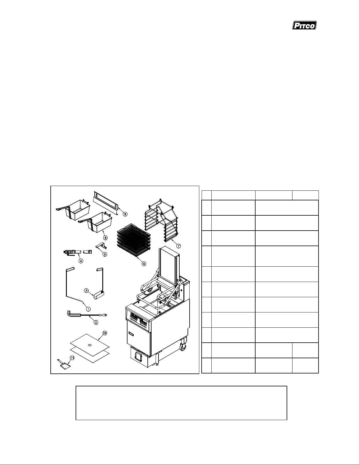
Refer to the table below to identify which accessories should be included with your appliance.
Locate your Pitco model number and serial number on the inner door of the appliance and the find
the date purchased. Write this information on the front cover of this manual for future reference.
If you have completed the above steps that are applicable to the appliance you purchased, the
appliance is now ready to be installed. Although it may be possible for you to install and set up your
new appliance, it is STRONGLY recommended that you have this done by qualified professionals. A
qualified professional will ensure that the installation is safe and meets local building and fire codes.
Accessories
# Description SG6H SFSG6H
Fry pot drain
1
clean out rod
Fry pot cleaning
2
brush
Fry pot crumb
3
scoop
Flexible gas
4
hose with
disconnect
5 Rack handle
6 Product racks
7 Rack holder
8 Basket hanger
9 Fry baskets
Standard
Standard
Standard
Optional
Standard with Lift
Assist
Standard with Lift
Assist
Standard with Lift
Assist
Optional in lieu of Lift
Assist
Optional in lieu of Lift
Assist
WARNING
DO NOT sit or stand on this appliance. The appliance’s front panel, tank,
splash back, tank cover, workshelf, drain board is not a step. Serious
injury could result from slipping, falling or contact with hot liquids.
2 L20-332, rev. 1 (05/11)
10 Filter paper n/a Standard
Filter shovel
11
scoop
n/a Standard
Page 7
MODEL SG6H FRYER INSTALLATION
1.2. INSTALLATION CLEARANCES
The clearances shown below are for combustible and non-combustible installations and will allow for
safe and proper operation of your appliance.
Combustible Construction Non Combustible Construction
Inches (centimeters) Inches (centimeters)
Back
Sides
Floor
6.0" (15.24cm) 0.0" (0.0cm)
6.0" (15.24cm) 0.0" (0.0cm)
6.0" (15.24cm) 6.0" (15.24cm)
In addition to the above clearances there must also be at least 16 inches (40.64cm) of aisle space in
front of the unit.
WARNING
DO NOT obstruct the flow of ventilation, or air openings
around the appliance. Adequate clearance around the
appliance is necessary for servicing and proper
component ventilation. Ensure that you meet the
DO NOT install this appliance next
to a water cooker. A splash over of
water into the hot oil may cause a
flash fire.
WARNING
minimum clearance requirements specified in this manual.
CAUTION
To prevent equipment damage and/or personal injury, do not tilt the appliance onto any
two of its casters or legs, or pull the appliance by the splash back.
1.3. LEG/CASTER INSTALLATION AND LEVELING
When you receive your appliance it is completely assembled with the possible exception of the legs
(or casters). This appliance must be installed with legs or casters; it cannot be curb mounted. Curb
mounting will seriously inhibit this appliance’s ability to effect proper component ventilation. The
legs/casters must be installed before connecting the appliance to the power supply. The legs/casters
provide the necessary height to meet sanitation requirements and assure adequate air supply to the
combustion system. Use the following procedure.
WARNING
This appliance must be installed with the legs or casters provided by the manufacturer.
Required tools: 7/16 “ wrench and socket and a large pair of water pump pliers.
1. Lay the appliance on its back, being careful not to
damage the splash back by pulling on it. Protect the
outside of the appliance with cardboard or a drop
cloth when laying it down.
2. Attach each leg/caster with the hex head screws and
nuts supplied. Each leg/caster requires four ¼-20 x
5/8” hex head screws and nuts. Insure that all
screws are tight.
3. Mount the screws from the inside of the appliance
with the nut on the outside (bottom) of the
appliance. The nuts have lock washers attached
to them, therefore it is not necessary to use
separate lock washers.
DO NOT install legs or casters, or
perform leveling procedure when
appliance is in operation or full of hot
liquids. Serious injury could result.
WARNING
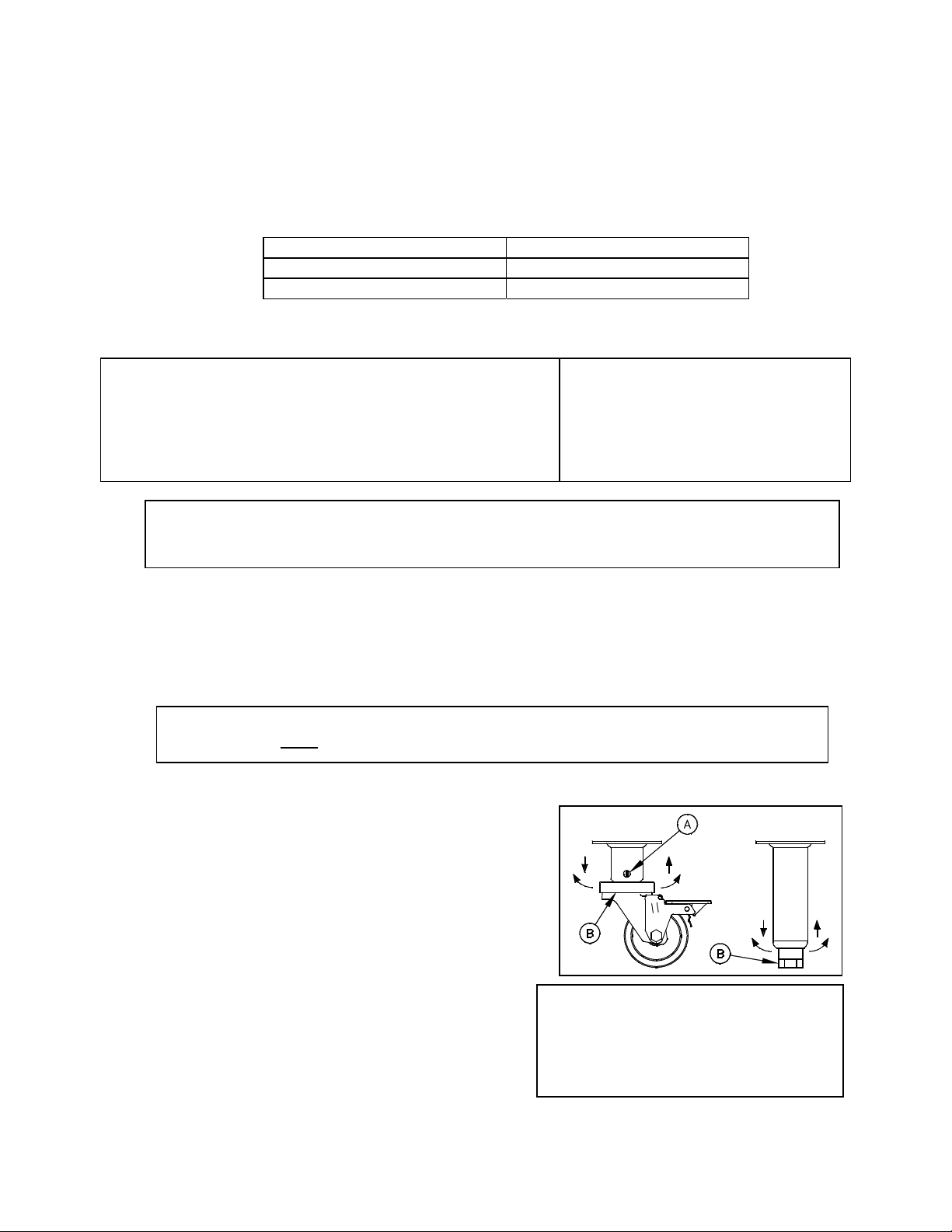
4. When all four legs/casters are securely mounted, stand the unit up, being careful not to put too
much weight on any one leg. Adjust the height and level the appliance by adjusting the leveling
devices (B) with water pump pliers. On casters, loosen 2 screws (A) before leveling, make your
height adjustments, then retighten.
L20-332, rev. 1 (05/11) 3
Page 8

INSTALLATION
y
1.4. GAS CONNECTION
Your appliance will give you peak performance when the gas supply line is of sufficient size to provide
the correct gas flow. The gas line must be installed to meet the local building codes or National Fuel
Gas Code ANS Z223.1 and NFPA 54 (latest editions). In Canada, install the appliance in accordance
with CSA B149.1 or .2 and local codes. Gas line sizing requirements can be determined by a qualified
installation professional, your local gas company or by referring to the National Gas Fuel Code,
Appendix C, Table C-4 (for natural gas) and Table C-16 (for propane). The gas line needs to be large
enough to supply the necessary amount of fuel to all appliances without losing pressure to any
appliance. A properly sized and installed gas line will deliver a supply pressure between 7.0” W.C.
(17.4mbars, 1.74kPa) and 10.0”W.C. (24.9mbars, 2.49kPa) natural gas or between 11.0”W.C.
(27.4mbars, 2.74kPa) and 13.0” W.C. (32.4mbars, 3.25kPa) propane to all appliances connected to
the supply line, operating simultaneously at full demand. The pressure at the gas valve shall not
exceed ½ PSI.
Each appliance is equipped to operate on one certain fuel type. The type of fuel with which the
appliance is intended to operate is stamped on the data plate, which is attached to the inside of the
door.
WARNING
NEVER supply the appliance with a gas other than the one that is indicated on the data
plate. Using the incorrect gas type will cause improper operation and could result in serious
injury or death. If you need to convert the appliance to another type of fuel, contact the
dealer
ou purchased it from.
NOTICE
NEVER use an adapter to make a smaller gas supply line fit the appliance connection. This
may not allow proper gas flow for optimum burner operation, resulting in poor performance
and improper operation.
1.4.1. QUICK DISCONNECT CONNECTION
Gas appliances equipped with casters must be installed with connectors that comply with the
Standard for Movable Gas Appliances, ANSI Z21.69 • CSA 6.16 latest edition. This connection
should include a quick disconnect device that complies with the Standard for Quick Disconnect
Devices for Use With Gas Fuel, ANSI Z21.41 • CSA 6.9 latest edition. When installing a quick
disconnect you must also install adequate means for limiting the movement of the appliance
without depending on the connector and quick-disconnect device or it’s associated piping to limit
the movement of the appliance. The restraining device should be attached to the appliance on the
back panel.
1.4.2. FUEL SUPPLY LINE LEAK AND PRESSURE TESTING
The fuel supply system must be tested before the appliance is used. If the fuel line is going to be
tested at a pressure greater than ½ PISG (3.45 kPa), insure that that appliance is disconnected
from the fuel line. If the fuel line is to be tested at a pressure equal to or less than ½ PSIG (3.45
kPa), the appliance can be connected during the test, but the unit’s gas valve must be shut. Test
all gas line connections for leaks with a solution of soap and water when pressure is applied.
4 L20-332, rev. 1 (05/11)
Page 9
MODEL SG6H FRYER INSTALLATION
A
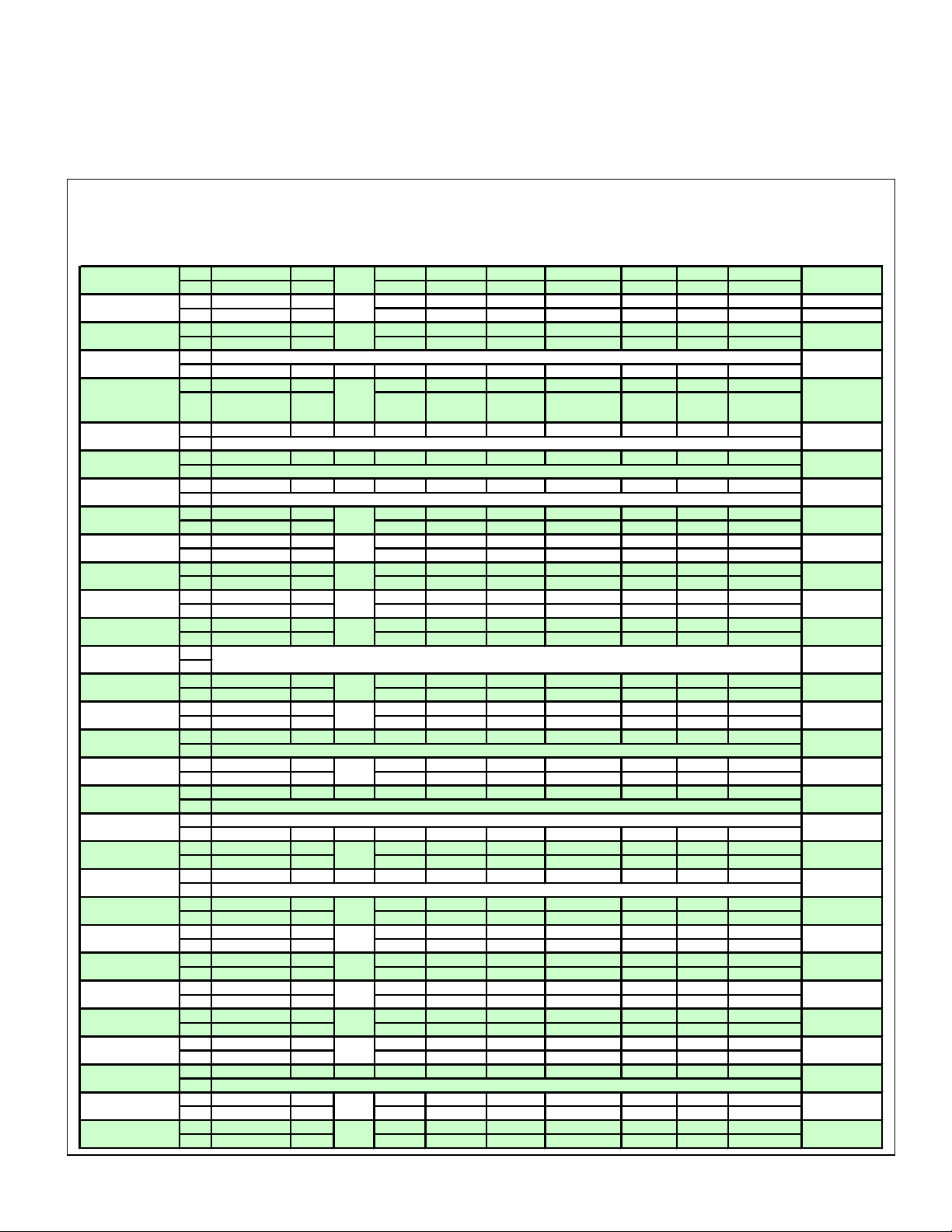
1.4.3. CE GAS TABLE (NOT APPLICABLE TO ALL MODELS)
Refer to the following table for gas specifications for the country of use. If the country of use is
NOT listed, refer to the information stamped on the data plate.
kW
Country
Austria (AT) 40
Belgium (BE)
Bulgaria (BG)
Cyprus (CY)
Czech Rep. (CZ)
Denmark (DK)
Estonia (EE)
Finland (FI)
France (FR)
Germany (DE)
Great Britain (GB)
Greece (GR)
Hungary
Iceland (IS)
Ireland (IE)
Italy (IT)
Lithuania (LT)
Luxembourg (LU)
Latvia (LV)
Malta (MT)
Netherlands (NL)
Norway (NO)
Poland (PL)
Portugal (PT)
Romania (RO)
Spain (ES)
Slovakia (SK)
Slovenia
Sweden (SE)
Switzerland (CH)
Turkey (TR) 40
Fuel Type
Nat G20 I2H 36.0 20 10 #41 N22 YES 3.8
LP G31 I3P 36.8 50/37 25.4 #53 LP16 YES 1.5
Nat G20/G25 I2E+ 36.0 20/25 10 #41/#38 N22 NO 3.8/4.4 5.61 mm
LP G31 I3P 36.8 50/37 25.4 #53 LP16 YES 1.5 N/
Nat G20 I2H 36.0 20 10 #41 N22 YES 3.8
LP G31 I3P 36.8 50/37 25.4 #53 LP16 YES 1.5
Nat
LP G31 I3P
Nat G20 I2H 36.0 20 10 #41 N22 YES 3.8
LP G31 I3P 36.8 50/37 25.4 #53 LP16 YES 1.5
Nat G20 I2H
LP
Nat G20 I2H
LP
Nat G20 I2H
LP
Nat G20/G25 I2Esi 36.0 20/25 10 #41/#38 N22 YES 3.8/4.4
LP G31 I3P 36.8 50/37 25.4 #53 LP16 YES 1.5
Nat G20/G25 I2ELL 36.0 20/25 10 #41/#38 N22 YES 3.8/4.4
LP G31 I3P 36.8 50/37 25.4 #53 LP16 YES 1.5
Nat G20 I2H 36.0 20 10 #41 N22 YES 3.8
LP G31 I3P 36.8 50/37 25.4 #53 LP16 YES 1.5
Nat G20 I2H 36.0 20 10 #41 N22 YES 3.8
LP G31 I3P 36.8 50/37 25.4 #53 LP16 YES 1.5
Nat G20 I2H 36.0 20 10 #41 N22 YES 3.8
LP G31 I3P 36.8 50/37 25.4 #53 LP16 YES 1.5
Nat
LP
Nat G20 I2H 36.0 20 10 #41 N22 YES 3.8
LP G31 I3P 36.8 50/37 25.4 #53 LP16 YES 1.5
Nat G20 I2H 36.0 20 10 #41 N22 YES 3.8
LP G31 I3P 36.8 50/37 25.4 #53 LP16 YES 1.5
Nat G20 I2H
LP
Nat G20 I2E 36.0 20 10 #41 N22 YES 3.8
LP G31 I3P 36.8 50/37 25.4 #53 LP16 YES 1.5
Nat G20 I2H
LP
Nat
LP G31 I3P
Nat G25 I2L 36.0 25 10 #38 N22 YES 4.4
LP G31 I3P 36.8 50 25.4 #53 LP16 YES 1.5
Nat G20 I2H
LP
Nat G20 I2E 36.0 20 10 #41 N22 YES 3.8
LP G31 I3P 36.8 37 25.4 #53 LP16 YES 1.5
Nat G20 I2H 36.0 20 10 #41 N22 YES 3.8
LP G31 I3P 36.8 50/37 25.4 #53 LP16 YES 1.5
Nat G20 I2H 36.0 20 10 #41 N22 YES 3.8
LP G31 I3P 36.8 50/37 25.4 #53 LP16 YES 1.5
Nat G20 I2H 36.0 20 10 #41 N22 YES 3.8
LP G31 I3P 36.8 50/37 25.4 #53 LP16 YES 1.5
Nat G20 I2H 36.0 20 10 #41 N22 YES 3.8
LP G31 I3P 36.8 50/37 25.4 #53 LP16 YES 1.5
Nat G20 I2H 36.0 20 10 #41 N22 YES 3.8
LP G31 I3P 36.8 50/37 25.4 #53 LP16 YES 1.5
Nat G20 I2H
LP
Nat G20 I2H 36.0 20 10 #41 N22 YES 3.8
LP G31 I3P 36.8 50/37 25.4 #53 LP16 YES 1.5
Nat G20 I2H 36.0 20 10 #41 N22 YES 3.8
LP G31 I3P 36.8 50/37 25.4 #53 LP16 YES 1.5
Gas
Appliance
Category
Input (Gross)
40
40
T H I S C O U N TR Y D O E S N O T U S E N A T U R A L G A S
40
40
40
NOT APPROVED FOR USE WITH LP GAS IN THIS COUNTRY
40
NOT APPROVED FOR USE WITH LP GAS IN THIS COUNTRY
40
NOT APPROVED FOR USE WITH LP GAS IN THIS COUNTRY
40
40
40
40
40
40
40
40
NOT APPROVED FOR USE WITH LP GAS IN THIS COUNTRY
40
40
NOT APPROVED FOR USE WITH LP GAS IN THIS COUNTRY
T H I S C O U N TR Y D O E S N O T U S E N A T U R A L G A S
40
40
40
NOT APPROVED FOR USE WITH LP GAS IN THIS COUNTRY
40
40
40
40
40
40
40
NOT APPROVED FOR USE WITH LP GAS IN THIS COUNTRY
40
kW
Input (Net)
36.8 50/37 25.4 #53 LP16 YES 1.5
36.0 20 10 #41 N22 YES 3.8
36.0 20 10 #41 N22 YES 3.8
36.0 20 10 #41 N22 YES 3.8
NO DATA AVAILABLE FOR THIS COUNTRY
36.0 20 10 #41 N22 YES 3.8
36.0 20 10 #41 N22 YES 3.8
36.8 50/37 25.4 #53 LP16 YES 1.5
36.0 20 10 #41 N22 YES 3.8
36.0 20 10 #41 N22 YES 3.8
Supply
Pressure
(mbar)
Burner
Pressure
(mbar)
Burner Orifice
Pilot Orifice
(code)
Governor
Nom rate
(m3/hr)
Orifice
Restrictor
N/A
N/A
N/A
N/A
N/A
N/A
N/A
N/A
N/A
N/A
N/A
N/A
N/A
N/A
N/A
N/A
N/A
N/A
N/A
N/A
N/A
N/A
N/A
N/A
N/A
N/A
N/A
N/A
N/A
N/A
L20-332, rev. 1 (05/11) 5
Page 10
INSTALLATION
,
1.5. ELECTRICAL CONNECTIONS
It is advised that this power supply be plugged into a wall receptacle that is controlled by the
ventilation control. This will prevent the appliance from being operated without the ventilator on. If
your appliance requires an electrical connection, the power requirements are listed below.
North America International
Input Voltage 120 VAC, 50/60 Hz 220, 230 or 240 VAC 50/60 Hz
Current per unit 0.7 Amp 0.4 Amp
Filter Current 7.5 Amp 4.2 Amp
Heat Tape 0.4 Amp 0.2 Amp
CAUTION
Connecting the appliance to the wrong power supply may damage the appliance and v oid
the warranty.
WARNING
This appliance must be connected to a power supply having the same voltage and phase as
specified on the data plate located on the inside of the appliance door.
WARNING
DO NOT attempt to connect the appliance to an electrical supply other then that indicated
on the data plate. Electrical connection should be performed by qualified personnel.
WARNING
The electrical connection used by this appliance must comply with local codes. If there are
no local codes that apply, refer to the National Electrical Code (NEC), ANSI/NFPA 70 for
installation in the US. In Canada, refer to CSA Standard C22.2 and local codes. In all other
cases
The appliance must be grounded in accordance with local code; if there is no local code,
comply with the NEC and ANSI/NFPA No. 70 latest edition (for US and Canadian
installations). In all other cases, refer to local and national codes and regulations. To
comply with European requirements, European models are equipped with an equalizationbonding clamp. An equalization bonding lead must be connected to this clamp to provide
sufficient protection against potential difference. This clamp, located on the rear of the
appliance is marked with the following universal symbol.
A country approved all pole circuit breaker with a minimum open contact gap of 3mm must
be used for proper installation. (CE countries)
This equipment must be installed so that the plug is accessible unless other means for
disconnection from the power supply (e.g. a circuit breaker) is provided.
If this appliance is permanently connected to fixed wiring, it must be connected by means
of copper wires having a temperature rating of not less then 167°F (75°C).
refer to local and national codes and regulations.
WARNING
WARNING
WARNING
WARNING
WARNING
All copper wiring for this appliance must be made in accordance with the wiring diagram(s)
located on the appliance.
6 L20-332, rev. 1 (05/11)
Page 11

MODEL SG6H FRYER INSTALLATION
plug;
WARNING
If your appliance is uses line current, it is equipped with an oil proof, electrical supply cord
with a three-prong safety plug. This is to protect operators from electrical shock hazard in the
event of an equipment malfunction. DO NOT cut or remove the grounding (third) prong from
this
1.6. VENTILATION AND FIRE SAFETY SYSTEMS
Your new appliance must have proper ventilation to function safely and properly. Exhaust gas
temperatures can reach as high as 1100 °F (593 °C). Therefore, it is very important to install a fire
safety system. Your ventilation system sho uld be designed to allow for easy cleaning. Frequent
cleaning and proper maintenance of the ventilation system and the appliance will reduce the chances
of fire. Ventilation and fire safety systems must comply to local and national codes. Refer to ANSI
83.11 for a list of reference documents that will provide guidance on ventilation and fire safety
systems. For installations in U.S. and Canada, additional information can be obtained from CSA
International, 8501 East Pleasant Valley Road, Cleveland, OH, 44131 or visit their website at
www.csa-international.org.
It is essential that the appliance be operated only when adequate ventilation is provided. Your
ventilation hood should be properly maintained. A qualified installation professional should ensure that
the hood is operating properly in conjunction with the appliance. Inadequate ventilation may not
properly evacuate appliance all emissions. Excessive or unbalanced ventilation may cause drafts,
which could interfere with proper operation of the pilot and burners. Leave at least 18 inches
(45.72cm) of open space between the flue of the appliance and the intake of the exhaust hood.
it should be plugged into a properly grounded three-prong receptacle.
WARNING
Ensure that your ventilation system does not cause a down draft at the appliance’s flue
opening. A down draft will not allow the appliance to exhaust properly and will cause
overheating, which may cause permanent damage. Damage caused by down drafts will not
be covered by the warranty. NEVER allow anything to obstruct the flow of combustibles or
ventilation exiting the appliance. NEVER place anything on top of the flue area, or block the
flue in any way. Never place a grease condensating drip pan over the flue opening.
WARNING
NEVER connect the ventilation blower or hood directly to the flue of this appliance. The
resulting increased flow of air through the combustion system will cause improper
operation, poor temperature recovery, poor ignition and could extinguish the pilot.
1.7. INSPECTION
Before you begin filling and adjusting the appliance,
perform the following visual checks:
After the appliance is in its permanent location, check
the levelness. Any additional leveling that is
necessary can be performed as previously described.
Ensure that the probe and high temperature limit is in
place and secure. Check the high limit bulb mounting
screws to ensure that they are tight.
Review the installation portion of this manual and
ensure that all steps have been followed and
executed properly.
1) Probe
2) High Temperature Limit
L20-332, rev. 1 (05/11) 7
Page 12

INSTALLATION
1.8. INITIAL ADJUSTMENTS
After your appliance has been properly installed as described in the installation section of this
manual, it will need to be adjusted to ensure that it will perform as designed. A qualified person must
perform these adjustments.
To perform these adjustments the following tools will be needed:
Manometer
Digital Thermometer (Temperature Probe)
DC Microammeter
1.8.1. FILLING THE APPLIANCE
Refer to the following procedure to fill the cook tank prior to operation.
1. Ensure that the drain valve is closed.
2. Fill the tank with oil/shortening until the oil/shortening reaches the level line(s). Never let the
oil/shortening level go below the MIN LEVEL mark stamped on the tank.
WARNING
Oil/shortening must completely cover the heat tubes at all times while appliance is on.
CAUTION
This appliance is not designed for cooking with water. Fill with oil/shortening only.
WARNING
During operation there is an open flame inside this appliance. The unit may get hot enough to
set near by materials on fire. Keep the area around the appliance free from combustibles.
1.8.2. LIGHTING INSTRUCTIONS
There is nothing to manually light on the electronic ignition system. Pilot ignition is performed and
controlled by the electronic ignition system. Refer to the following instructions to light the
appliance.
1. Open the gas supply valves to the appliance.
2. Turn the gas valve knob to the ON position.
3. Turn the controller on.
Solid State Thermostat:
Assure the Melt switch is in the correct position.
Turn the I/0 (ON/OFF) switch to the I (ON) position
Computer and Digital Control:
Press the
*The specified button may appear slightly different then shown. Refer to the
operator’s manual for your appliance’s specific control type to determine the exact
appearance of each button and display.
*
button to turn the controller on.
ON
OFF
Solid State Melt
Switch
Solid State
I/0 ON/OFF
Switch
4. The main burners will light and be controlled by the thermostat.
8 L20-332, rev. 1 (05/11)
Page 13

MODEL SG6H FRYER INSTALLATION
A
1.8.3. PILOT FLAME ADJUSTMENT
Perform this procedure with the pilot lit.
Note: This procedure requires the use of a DC microammeter.
1. Connect the DC microammeter between the flame
sensor terminal and the flame sensor lead.
Observe proper polarity: if the meter needle goes
below 0, reverse the leads. The current reading
must be 1.0 A or greater, (0.15 A or greater for
CE units).
2. Adjust the current reading to the required level by
adjusting the pilot flame. Remove the pilot
adjustment screw cap screw to expose the pilot
ON
adjustment screw. Turning the pilot adjustment
screw clockwise will decrease the size of the pilot
OFF
flame and flame sense current. Turning the pilot
adjustment screw counterclockwise will increase
the pilot flame size and the flame sense current.
3. Rotate the screw in the direction needed to
achieve a reading of 1.0 A or greater, (0.15 A or
greater for CE units).
Note: Allow 3 to 5 minutes between flame
adjustments to allow the reading to stabilize.
4. Once the pilot flame has been adjusted properly,
replace the pilot adjustment screw cap screw and
remove the microammeter.
) Burner Pressure Tap
B) Pilot Adjustment Screw Cap
C) ON/OFF Knob
D) Burner Pressure Adjustment Screw Cap
E) Inlet Pressure Tap
L20-332, rev. 1 (05/11) 9
Page 14

INSTALLATION
1.8.4. MAIN BURNER SYSTEM ADJUSTMENT
For the main burners to operate the gas supply valve must be open and the thermostat must be
turned on. The main power switch must be on. The main burners receive gas from the main ga s
supply through the thermostatically controlled valve. When the water temperature drops below
the preset temperature the gas control valve opens.
The main burners must be adjusted to deliver optimum flame. Refer to the following procedure to
adjust the main burners.
1. Ensure that the main gas valve is shut off, remove the manifold pressure tap plug and
connect an accurate pressure gauge (range of 0-16 “W.C. (39.85mbar, 3.98kPa) in 0.1”
(.25mbar, .02kPa) increments) or manometer.
2. Turn on this and all appliances connected to the gas supply line and light their main burners.
The pressure reading of the installed pressure gauge should not drop from the required
installation pressure. Any loss of pressure indicates inadequate supply line installation,
which will cause poor performance of all appliances during peak usage.
3. The installed pressure gauge should be the same, ±0.1” W.C. (.25mbar, .02kPa), as that
marked on the data plate on the inside door of the appliance. If the pressure is correct, go to
step 6, if it is not, adjust the pressure as outlined in step 4.
4. To adjust the pressure, remove the regulator adjustment screw cap and, with a flat head
screwdriver, adjust the regulator screw until the proper burner pressure is reached. Turning
the screw clockwise will increase the burner pressure. Turning the screw counterclockwise
will decrease the burner pressure.
5. When the pressure is correct, replace the regulator adjustment screw cover.
6. Turn off the ALL appliances, shut the main gas valve to your Pitco appliance and remove the
pressure gauge. Apply pipe joint compound to the manifold pressure tap plug and reinstall it.
10 L20-332, rev. 1 (05/11)
Page 15

MODEL SG6H FRYER INSTALLATION
CAUTION
Be careful not to disturb the probe and high temperature
limit during operation and cleaning of this appliance.
1.9. INITIAL CLEANING
When your appliance is shipped, many of its parts are covered with a thin coat of oil for protection.
Before the appliance is ready for cooking it must be cleaned. This will remove the oil coating and any
foreign matter that may have accumulated during storage and shipment. Refer to the following
procedure to clean the appliance.
WARNING
Wear protective gloves and clothing when cleaning and draining the appliance and
when disposing of water. The water is extremely hot and can cause severe injuries.
CAUTION
DO NOT leave the appliance unattended during cleaning. Never let the liquid level
go below the heat tube.
1. Read the “operation” section of this manual prior to filling or operating the a ppliance.
2. The following steps should be followed using a grease dissolving commercial cleaner.
WARNING
Use a commercial grade cleaner formulated to effectively clean and sanitize food
contact surfaces. Read the directions and precautionary statements before use.
Particular attention must be paid to the concentration of cleaner and the length of
time the cleaner remains on the food contact surfaces.
3. Following the manufacturer’s directions, clean the tank interior and all other food contact
surfaces.
4. When cleaning is complete, rinse the inside of the tank thoroughly with cool water. Continue
to rinse the tank until the cleaner has been completely and thoroughly rinsed from the tank.
5. Using a clean dry cloth, wipe out all of the water.
6. Repeat the previous steps to clean the bread and batter station or filter pan if equipped.
L20-332, rev. 1 (05/11) 11
Page 16

OPERATION
2. OPERATION
An operator’s manual for your appliance’s specific control type should be included with this manual.
Refer to that manual prior to operating this appliance.
2.1. OPERATIONAL FEATURES
The diagram below outlines some of the key operational components of your appliance. Refer to the
following sections of this manual to learn more about these features.
12 L20-332, rev. 1 (05/11)
Page 17

MODEL SG6H FRYER OPERATION
2.1.1. BASIC OPERATIONAL FEATURES
1. Cook Tank
2. Front Panel
If the appliance is equipped with a
computer or digital controller, it will be
located on the front panel.
3. Door (Shown Open)
Provides access to,
the drain valve handle, tank drain
outlet and high temperature reset
button
Solid State thermostat (if
equipped).
gas valve, pilot, burners, gas
shutoff valve and self cleaning
burner system (if equipped).
Filter models: Filter pump,
oil/shortening return handle and
flush hose (if equipped).
4. Drain Valve Handle (Blue) (Shown
in the closed position)
Opens the drain valve so
oil/shortening can be drained from the
cook tank.
If the drain valve interlock feature is
equipped, the appliance will stop
heating if the drain valve is opened.
6. High Temperature Reset Button
This button may need to be pressed in
the event that the high temperature
limit has tripped.
7. Rack Lift Assist
Aids in lifting racks in and out of tank.
8. Gas Valve Knob
The gas valve controls the flow of gas
to the pilot and burners.
Turning the gas valve knob to the OFF
position shuts off the gas supply to the
pilot and burners
9. Pilot
The pilot lights the burners when the
water in the cook tank requires more
heat.
10. Burners
Heats the oil/shortening inside the
cook tank.
11. Self Cleaning Burner System (if
equipped)
The self cleaning burner system
cleans the burners when the
appliance is turned ON.
5. Tank Drain Outlet
Oil/shortening exits the cook tank
through the drain outlet when draining.
2.1.2. OPERATION FEATURES SPECIFIC TO MODELS WITH FILTERS.
12. Filter Pump
The filter pump is used to pump
Filter media is located inside the filter
pan.
oil/shortening from the filter pan back
into the cook tank or through the flush
hose (if equipped).
16. Flush Hose Connection (if
equipped)
Connect the flush hose here when
13. Filter Pump Reset Button
using the flush hose feature.
This button may need to be pressed in
the event that the filter pump circuit
breaker has tripped.
17. Flush Hose Handle (Yellow) (if
equipped)
Pulling this handle starts the flow of
14. Oil Return Handle (Red)
Oil exits the cook tank through the
drain outlet when draining.
oil/shortening through the flush hose.
Pushing the handle in will stop the
flow of oil/shortening through the flush
hose.
15. Filter Pan
Oil drained from the cook tank goes
into the filter pan.
18. Waste Oil Management Handle
(Brown) (if equipped)
Directs the oil to a waste oil container.
L20-332, rev. 1 (05/11) 13
Page 18

OPERATION
p
2.2. FILLING THE COOKER TANK
Both liquid and solid shortening can be used in this appliance, but liquid is preferred. If solid
shortening is used it is recommended that you melt the shortening before adding it to the
appliance. You can melt solid shortening in the appliance, but you must be very careful not to
scorch the shortening.
Tank Capacity
This appliance is NOT designed for cooking with water.
Model Capacity
SG6H 85 lbs. (38 kg)
2.2.1. FILLING THE TANK WITH LIQUID SHORTENING
To fill the tank with liquid shortening refer to the following procedure.
1. Ensure that the drain valve is completely closed and that there is no residual moisture
in the tank.
2. Fill the tank with oil. You may fill the tank to the “MIN LEVEL” mark or slightly below the
nominal level mark: the oil will expand slightly when it heats up, raising the level
slightly.
2.2.2. FILLING THE TANK WITH SOLID SHORTENING
To fill the tank with solid shortening refer to the following procedure.
WARNING
NEVER melt blocks of
solid shortening on top of
the heat tubes This will
cause a fire and could
result in personal injury.
Fill with oil or shortening only.
CAUTION
1. Remove the tank rack.
2. Cut the solid shortening
into cubes no larger than
one inch. ALWAYS pack
the shortening below,
between, and on top of the
burner tubes. Do NOT
leave any large air gaps.
Use care when packing the solid shortening into the tank. Do NOT bend or break the
temperature or high limit sensor probes. If these are damaged the appliance will not
function properly.
3. Once the appliance tank is firmly packed with shortening, the shortening must be
melted. Melt the shortening by cycling the
main burners on for 4 seconds and off for 30 seconds repeatedly, using the thermostat
knob. If your appliance has a Melt Cycle option, use this to melt the shortening
automatically.
WARNING
Oil/shortening must completely cover the heat tubes at all times while appliance is on.
1. Fill Line
2. Heat Tubes
3. Solid Shortening
4. Excessive Air Ga
s
14 L20-332, rev. 1 (05/11)
Page 19

MODEL SG6H FRYER OPERATION
2.3. APPLIANCE START UP
Refer to the following procedure to start the appliance prior to operation.
1. Ensure that the drain valve is closed.
2. Fill the cook tank with oil/shortening. (See section 2.2 “Filling the Cook Tank”)
3. Light the appliance. (See “Lighting Instructions” section)
WARNING
NEVER operate the appliance with an empty fry tank. It will void the warranty.
4. If the appliance is equipped with a controller, turn the controller on.
Solid State Thermostat:
Turn the I/0 (ON/OFF) switch to the I (ON) position
Computer and Digital Control:
Press the
*The specified button may appear slightly different then shown.
Refer to the operator’s manual for your appliance’s specific control
type to determine the exact appearance of each button and display.
*
button to turn the controller on.
Solid State
I/0 ON/OFF
Switch
5. If the appliance is equipped with a thermostat knob, turn the knob to the desired temperature
setting.
6. The appliance is now on and heating the oil/shortening in the cook tank.
WARNING
Oil/shortening level should NOT be allowed to fall below the minimum indicated level line at
any time. Dry firing of the fry tank will shorten tank service life and will void your warranty.
L20-332, rev. 1 (05/11) 15
Page 20

OPERATION
2.4. COOKING
To ensure the quality of the food you cook in this appliance, follow the preparation instructions from
the food manufacturer. When the appliance is not in use, the oil/shortening should be cooled and
covered to prevent contamination. A maximum load of 1.5 lbs. (0.7kg) per basket is recommended.
Exceeding this recommendation may affect food quality and could cause surge boiling.
WARNING
Dry fired heat tubes are extremely hot, will shorten its service life and may void your
warranty.
2.4.1. TIMER OPERATION
Not all control types include timers. Timers provide accurate cook times for multiple product
quantities and types. Refer to the operator’s manual for your appliance’s specific control type to
determine how to set the cook timers if equipped.
To start a timer: Press the appropriate timer button.
Typical Timer Bu ttons*
2.4.2. ADDITIONAL CONTROLLER FUNCTIONS
Some controllers have additional functions not described in this manual. If your appliance’s
controller has additional functions, refer to the controller’s operation manual to access these
functions.
*The specified buttons and/or displays may appear slightly different then shown. Refer to
the operator’s manual for your appliance’s specific control type to determine the exact
appearance of each button and display.
2.5. COOKING TIPS
Always follow the food manufacturer’s directions.
The lower the oil temperature, the longer the cooking time and the greater the fat absorption.
NEVER overfill fryer baskets. Overfilling can result
in soggy, greasy product.
When removing baskets from the cook tank, shake
gently to remove excess oil.
Never leave a basket over the fryer. The heat from
the cook tank will continue to cook the product.
Oil/shortening quality can effect product quality.
Keep salt and water away from the oil/shortening to
maintain its life. Oil/shortening filtration removes
crumbs from the oil which will also extend its life.
Typical French Fry Cook Times
Fry Thickness 350F 360F 370F
Thin 2:45 2:30 2:15
medium 3:45 3:30 3:15
Thick 4:15 4:00 3:45
This table is for reference only. Please
refer to the product manufacturer’s
specifications to determine exact cook
temperatures and times.
16 L20-332, rev. 1 (05/11)
Page 21

MODEL SG6H FRYER OPERATION
2.6. APPLIANCE SHUTDOWN
There are two shutdown modes of appliance operation: STANBY and COMPLETE. The standby
mode removes the ability of the appliances main burners to operate. Complete shutdown turns off the
gas supply to the appliance. Refer to the following procedures to enter the appropriate shutdown
mode.
2.6.1. STANDBY MODE
1. Turn the temperature controller or thermostat OFF.
Solid State Thermostat:
Turn the I/0 (ON/OFF) switch to the I (OFF) position
Computer and Digital Control:
Press and hold the
*
button to turn the controller OFF.
*The specified button may appear slightly different then shown. Refer to the
operator’s manual for your appliance’s specific control type to determine the exact
appearance of each button and display.
WARNING
NEVER leave the appliance in
standby mode for prolonged
periods or overnight.
2.6.2. COMPLETE SHUTDOWN
1. Turn the temperature controller or thermostat OFF.
Solid State Thermostat:
Turn the I/0 (ON/OFF) switch to the I (OFF) position
Computer and Digital Control:
Press and hold the
*
button to turn the controller OFF.
*The specified button may appear slightly different then shown. Refer to the
operator’s manual for your appliance’s specific control type to determine the exact
appearance of each button and display.
2. Turn the ON/OFF knob on the gas valve clockwise to the OFF position.
3. The appliance is now completely shut down and can be cleaned if desired.
ON
OFF
L20-332, rev. 1 (05/11) 17
Page 22

PREVENTATIVE MAINTENANCE
3. PREVENTATIVE MAINTENANCE
3.1. DAILY PREVENTATIVE MAINTENANCE
Performing the preventative maintenance steps below on a daily basis will keep your equipment safe
and at peak performance. During the cooking process, oil/shortening may spill and splatter and
requires immediate attention. Furthermore, during the cooking process, particles, crumbs and
crackling collect inside the cooker tank reducing product quality and decreasing oil/shortening life. If
you are producing high quantities of fried food and/or frying heavily battered food, it may be
necessary to perform these steps more then once a day.
WARNING
Filtering may require contact with hot surfaces. Wear oil proof
insulated gloves while performing any filtering operation. Serious
injury could result from direct contact with hot surfaces and/or oil.
3.1.1. FILTERING WITH A FILTER DRAWER (IF EQUIPPED)
Refer to the following procedure to filter when the appliance is equipped with a filter drawer.
1. Turn the appliance OFF.
2. Pull the blue drain handle down to drain oil/shortening from the cooker tank into the filter pan.
3. Pull the red handle to turn the pump on to circulate oil/shortening through the filter media.
4. To refill the tank, lift the blue drain handle up.
5. When the tank has completed filling, push the red handle to deactivate the pump.
6. Assure that the oil/shortening level is above the minimum level line. Additional oil may need
to be added to the cook tank.
7. The oil/shortening in the cooker tank has now been filtered.
8. Replace the filter media and clean the filter pan following the procedures mentioned in this
manual.
3.1.2. FLUSH HOSE OPERATION (IF EQUIPPED)
The cooker tank can be rinsed cleaned by using a filter flush hose (if equipped). Refer to the
following procedure to operate the filter flush hose.
1. Turn the appliance OFF.
2. Pull the blue drain handle down to drain oil/shortening from the cooker tank into the filter pan.
3. Connect the filter flush hose to the quick connecting fitting.
4. Point the filter hose nozzle outlet into the cooker tank.
5. Pull the yellow handle to turn the pump on and allow oil/shortening to flow through the flush
hose.
6. To refill the tank, lift the blue drain handle up.
7. When the tank has completed filling, push the yellow handle to deactivate the pump.
18 L20-332, rev. 1 (05/11)
Page 23

MODEL SG6H FRYER PREVENTATIVE MAINTENANCE
3.1.3. REPLACING THE FILTER MEDIA (IF EQUIPPED)
Refer to the following procedure to replace the filter media if the appliance is equipped with a filter
drawer.
1. Detach the pickup tube from the filter pickup
assembly by unscrewing it (counterclockwise),
at the knurled fitting, from the threaded fitting on
the filter screen.
2. Slide off the filter paper clip and remove used
filter paper from filter screen. Replace with new
filter paper, ensuring that the hole in the paper is
on the top, so that threaded fitting in filter screen
protrudes through it.
3. Fold filter paper to the underside of the filter
screen and replace filter paper clip.
4. Re-attach filter pickup tube to the filter screen by
screwing it (clockwise) into the threaded fitting in
filter screen.
1. Filter Pan
2. Filter Pickup Assembly
3. Filter Strainer Cap
4. Filter Paper
5. Reinstall the filter pickup assembly into the filter
5. Filter Screen
system by placing the newly covered screen
portion of the assembly into the filter pan and connecting the quick disconnect on the filter
pickup assembly into white donut fitting on the left-hand side of the appliance. Ensure that
it snaps tightly and securely into donut fitting.
WARNING
The power supply must be disconnected before cleaning and servicing this appliance!
3.1.4. APPLIANCE INSPECTION
Check that the high temperature limit and temperature probe are in the correct position and
secured in place.
Check that wires and cords are not frayed or loose in and out of the cabinet.
Check around the appliance for loose parts or accessories that need to be secured or other
foreign items (ex: Aerosol cans) that should be removed from the area.
Check for oil/shortening leaks around the in and out of the cabinet and around the
appliance.
WARNING
Wear protective gloves and clothing when cleaning and draining the appliance and
when disposing of water. The water is extremely hot and can cause severe injuries.
L20-332, rev. 1 (05/11) 19
Page 24

PREVENTATIVE MAINTENANCE
3.1.5. CLEANING THE COOK TANK
1. Turn the appliance off. Drain all the oil/shortening from the tank and allow the tank to cool.
Read the operation section of this manual prior to filling or operating the appliance.
WARNING
2. Remove baskets, tank
rack and basket hanger
for cleaning.
3. Using the cleaning brush, remove all the loose debris and scrub all tank surfaces.
4. For tougher carbonized oil/shortening and carbon buildup scrub tank using a Scotchbrite or
other abrasive pad.
5. Wipe residue with a clean damp cloth and carefully dry any remaining oil/shortening
droplets from the tank before returning oil/shortening into the tank.
6. Clean and dry baskets, tank rack and basket hanger before reinstalling.
3.1.6. CLEANING THE CABINET
1. Wipe any spilled oil/shortening, dust and lint from the cabinet exterior with a clean damp
cloth and a mild food grade detergent .Be careful not to get any water or detergent in the
oil/shortening. Use a nonabrasive pad for tougher stains if needed.
2. Remove detergent from all surfaces.
3. Cleaning the interior cabinet requires a clean cloth to remove any oil/shortening, dust, lint
or filter powder (i.e.: Magnesol) from the interior of the cabinet.
3.1.7. FILTER CLEANING (IF EQUIPPED)
1. Unscrew filter strainer cap from pickup tube and gently tap it to dislodge any crumbs from the
slots. Use a clean cloth to remove any remaining crumbs and reattach.
DO NOT leave the appliance unattended during cleaning.
WARNING
2. Scrape all loose debris and crumbs from filter pickup assembly and filter pan with the filter
scoop shovel.
3. Remove filter pickup and place in pot sink, power soak sink or dishwasher for cleaning. Be
sure to rinse thoroughly and dry all surfaces before re-assembly.
4. Wipe the filter pan with clean damp cloth and a food grade detergent. If necessary place pan
in pot sink to rinse all the detergent from the surfaces and dry all surfaces before reassembly.
3.2. WEEKLY PREVENTATIVE MAINTENANCE
Performing the preventative maintenance steps above on a daily basis will keep your equipment
clean and safe. On a weekly basis these additional steps should be performed.
1. Turn the fryer off. Allow the oil/shortening to cool to before pulling the fryer away from the hood.
Hint: This maintenance may be ideal to perform on the day the oil/shortening is being changed
so no oil/shortening is present in the tank or filter.
2. Disconnect the power cord(s), gas hose and retention lanyard.
3. Wearing your protective gear, pull the fryer away from the hood.
4. Check that vent hood drip cup is empty and not dripping oil/shortening into the flue.
5. Check that the hood baffles are clean and not dripping oil/shortening into the flue.
20 L20-332, rev. 1 (05/11)
Page 25

MODEL SG6H FRYER PREVENTATIVE MAINTENANCE
6. Clean the fryer sides, back and the flue area, it may be necessary to use a non-abrasive pad to
scour and a putty knife to scrape the oil/shortening buildup. With a clean damp cloth and food
grade detergent wipe the area clean.
7. Wipe up any excessive oil/shortening on the power cord(s) and gas hose with a dry cloth.
8. Check flue pipe for any foreign debris/object and remove if found.
9. Reattach power cord(s), gas hose, retention lanyard and push fryer back under the hood.
3.3. MONTHLY PREVENTATIVE MAINTENANCE
Food debris and oil/shortening can buildup inside the tank. Performing the monthly preventative
maintenance steps below will keep your equipment safe and at peak performance. If you are
producing high quantities of fried food and/or frying heavily battered food, it may be necessary to
clean these components more then once a month.
3.3.1. BOIL OUT PROCEDURE
Wear protective gloves and clothing when cleaning and draining the appliance. Oil/shortening
may spatter and will cause injury to personnel.
1. Read the “operation” section of this manual prior to filling or operating the appliance.
2. Turn the appliance off. Drain all the oil/shortening from the tank and allow the tank to cool.
The container must also be able to withstand 400F (205C) temperatures.
3. Remove baskets, tank rack and basket hanger for cleaning.
4. Remove and discard any large debris inside the tank.
5. Close the drain valve and fill the tank with potable water to the level lines.
6. Place the appliance into boil mode:
Models with Solid State Thermostat: Put the thermostat into boil mode by flipping the power
switch in the following order (I- O - I - O - I) within 3 seconds. The power (green LED) and
heating (yellow LED) will be lit and the check (yellow LED) flashing.
Models with Digital Control: Turn the appliance ON. Press the
key and the ” key
simultaneously to enter boil mode.
Models with Computer: Turn the appliance ON. The controller will recognize that there is
water in the tank and automatically enter boil mode. To enter boil mode manually, press the
Temp Key then keys 2, 1, 2 for degrees F or 1, 0, 0. for degrees C.
7. Once the water reaches a simmer, add 8 to10 ozs (227 to 283 g) of Pitco cleaner for every 25
lbs (11.3 kgs) of oil/shortening your fryer is rated to hold.
8. Simmer for 1 minute. (The water should never be allowed to boil as this may splash over the
tank side and cause permanent damage to the components.)
9. Turn the appliance OFF and allow the fryer to soak for 15 to 30 minutes, allowing the cleaner
to soften the oil/shortening deposits and carbon.
10. Scrub the inside of the tank using a cleaning brush safe for hot water. Care must be taken to
remove all the foreign material on the tank, sidewalls and other components in the tank.
11. Drain the water from the tank.
L20-332, rev. 1 (05/11) 21
Page 26

PREVENTATIVE MAINTENANCE
12. Once the tank has cooled, rinse with clean potable water thoroughly.
13. Remove all remaining water and residue with a clean dry cloth.
14. Clean and dry baskets, tube rack and basket hanger before reinstalling
15. Close the drain valve and fill the cooker tank with oil/shortening.
3.3.2. TEMPERATURE CHECK
1. Use a high grade pyrometer or digital thermometer suitable for temperature up to 380F.
Place the thermometer in the oil above the tip of the fryer’s temperature probe with in 1”. Be
sure not to touch the heat tube since this will measure incorrect temperatures.
2. Check that the controllers setpoint and thermometer is within +/- 5F. If your measurement
are off, re-measure again before contacting an Authorized Service Company for further
assistance.
3.4. ANNUAL/PERIODIC PREVENTATIVE MAINTENANCE AND INSPECTION
This section should ONLY be performed by a qualified service technician as part of a regular kitchen
maintenance program. This inspection should take place a minimum of once a year by an Authorized
Service Technician recommended by Pitco. It may be
necessary perform this inspection more then once a year.
The power supply must be
3.4.1. SAFETY EVALUATION
Check power cord and plug.
Check all exposed wiring connections, switches, and
indicator lights.
Check legs, casters, wheels, plate welds and ensure all nuts and bolts are secured. (if
equipped)
Check conditions of flexible gas line and verify fryer retention / lanyard system is in place.
disconnected before cleaning
and servicing this appliance!
WARNING
3.4.2. MECHANICAL INSPECTION
Check frypot for shortening leaks and excessive oil build up
Check for oil migration (Clean as required)
Check hood drain cup, ensure it is empty and not dripping into the flue.
Check hood baffle for clean surface, oil/water condensate can drip on an d into the flue.
Check flue for foreign debris and hood down draft currents.
Check drain/filtration system (if equipped) for leaks
Check for missing fryer parts, i.e.: cover strips
Check for missing fasteners
3.4.3. TEMPERATURE CONTROL SYSTEM
Check electrical connections and harnesses
Check temperature probes and limits for carbon build up and plating. Clean a s re quired
Check proper mounting of probes and sensors and all fasteners a re secure.
Check thermistor probe resistances for stability.
Check DVI Drain Valve Interlock drops out controller.
Check Controller/thermostat features to ensure they are functioning.
Check Temperature Calibration
22 L20-332, rev. 1 (05/11)
Page 27

MODEL SG6H FRYER PREVENTATIVE MAINTENANCE
3.4.4. FILTER SYSTEM (IF EQUIPPED)
Check electrical connections and harnesses.
Check IEC power cords are fully engaged and secure.
Check for any air or shortening leaks and for excessive oil build-up.
Check O-Ring on filter pickup tube and replace as needed.
Check filter strainer on pickup tube.
Check operation of drain valve and DVI drain valve interlock.
Check operation of return oil valve and its pump switch.
Check operations of flush hose quick disconnect (if equipped), clean and lubricate as
needed.
Check all hardware in filter pan.
Check filter operation by filtering the fryers.
Check pump motor amp draw compare to nameplate amperage.
Check pump and motor, clean any excess oil from pump assembly.
Check all filter hoses for leaks and integrity.
3.4.5. CONTROL BOX & ELECTRICAL COMPONENTS
Verify that all components (transformer, terminal block, relays, drain switches, etc…) are in
good condition. Verify that wires are tight and in good condition.
Verify enclosures are free of leaks. Check for water stains and wet surface s.
Verify that the covers and panels are in tact and provide a safe condition. Check for loose
parts.
Verify power cord is in good condition. Check for frayed or exposed wires. Verify that the
insulation is in good condition and the attachment to the appliance is tight.
3.4.6. GAS COMBUSTION SYSTEM
Check for gas leaks.
Check and clean vent tube on gas valve pressure regulator.
Check burners, clean debris and grease from pilot and pilot orifice tips.
Check self cleaning burner system (if equipped) that it activates when the appliance is turned
on and NOT during normal cooking & idle periods.
Check and adjust burner manifold gas pressure to nameplate reading.
Check incoming gas pressure when all gas appliances are on.
Check ignition system and adjust pilot flame as required.
Check flame sensor reading.
Check gap spacing and clean igniter.
Recheck for gas leaks after inspection.
3.5. VENTILATION HOOD
Proper ventilation hood operation is very important for the correct operation of this appliance and the
safety of personnel. The ventilation hood should be inspected at the time of installation of this
appliance to insure that it will operate properly in conjunction with the appliance. A regular schedule
of examination, in accordance with ANSI/NFPA 96 latest edition and/or local codes must be followed.
L20-332, rev. 1 (05/11) 23
Page 28

TROUBLESHOOTING
4. TROUBLESHOOTING
4.1. POWER FAILURE
If electric power is removed for any reason, the appliance will shut down.
Wait five minutes after the power is restored before attempting to restart the appliance. This will allow
time for any gas that may have accumulated in the burner or tubes to dissipate.
To restart the appliance, follow the appliance start up procedure in section 2.2.
CAUTION
DO NOT attempt to operate this appliance during a power outage.
4.2. HIGH TEMPERATURE LIMIT
This appliance is equipped with a high temperature limit switch. The high temperature limit switch will
stop the appliance from functioning if the internal cook tank reaches an unsafe temperature. In the
event that the high temperature limit has tripped, Please refer to the following procedure to reset the
switch.
a. Turn the appliance off.
b. Allow the appliance ample time to cool to room
temperature.
c. Add oil/shortening to the cook tank as needed.
d. Press the high temperature reset button if equipped.
e. The high limit switch is now reset and the appliance is
ready for start up.
WARNING
DO NOT add oil/shortening to the tank until it has been given ample time to cool down.
Failure to do so may result in damage to the appliance and/or injury to the operator.
4.3. DRAIN VALVE INTERLOCK
If your appliance is equipped with a drain valve interlock circuit, the appliance will stop heating if the
tank drain valve is opened. If your appliance is equipped with a float switch, the appliance will stop
heating if the oil/shortening level reaches an unsafe height. In some cases the appliance will turn off.
Refer to the following procedure to resume operation after the drain valve interlock is tripped.
1. Turn the appliance OFF (if not already OFF).
2. Close the tank drain valve and fill the tank with oil/shortening.
3. Turn the appliance ON.
High Temperature Reset Button
24 L20-332, rev. 1 (05/11)
Page 29

MODEL SG6H FRYER TROUBLESHOOTING
4.4. SELF CLEANING BURNER SYSTEM (NOT ON ALL MODELS)
If your appliance is equipped with the self cleaning burner system, the appliance should behave as
outlined in the table below. A cleaning cycle will execute every time the appliance is turned “ON” from
an “OFF” state. The thermal cut out switch is designed to disable the appliance if the Self Cleaning
Burner System malfunctions and remains activated for an extended period of time or if there is a
downdraft into the flue or a blocked flue situation.
Event Duration Indication
Turn appliance “ON” N/A
Control Illuminates, pilot sparks and ignites. Pre-Purge
pulse is initiated.
Pre-Purge Pulse 2 seconds Appliance operates briefly and stops. Pilot remains lit.
Interwaiting period 1 5 seconds Appliance does not operate. Pilot remains lit.
Main valve operates, lighting main burners. SCBS valve
Cleaning Pulse 6 seconds
operates, feeding gas to the SCBS Arm. The SCBS arm
ignites, initiating a brief burn at the main burner orifice of
each burner.
Interwaiting period 2 8 seconds
The Main and SCBS valves de-energize for this period.
The pilot remains lit.
The appliance operates normally and begins to heat up.
Normal operation
resumes
N/A
The SCBS Valve remains de-energized until power to
the appliance is recycled. There is no flame on the
SCBS Arm. There is no burn at the main burner orifices.
L20-332, rev. 1 (05/11) 25
Page 30

TROUBLESHOOTING
4.5. TROUBLESHOOTING CHARTS
4.5.1. FRYER TROUBLESHOOTING CHART
Problem Probable Causes Corrective Actions
No power to appliance. Check main building power supply.
Controller not turned on. Turn on controller.
Controller does
not activate.
Controller is on
and appliance will
not heat up.
Power Cord loose or not
connected.
Main circuit breaker to
appliance has tripped.
Appliance fuse has blown. Contact Authorized Service Company.
High temperature limit has
tripped.
SCBS thermal limit switch has
tripped.
Connect power cord.
Reset circuit breaker
Allow appliance to cool and reset High
temperature limit.
Depress button on thermal limit switch to reset. If
problem continues, Contact Authorized Service
Company.
Appliance will not
maintain
temperature
properly.
Computer display
shows off and can
not be turned on.
4.5.2. FILTER TROUBLESHOOTING CHART (IF EQUIPPED)
Problem Probable Causes Corrective Actions
Filter pump does
not activate.
Oil/shortening is
returning to the
tank slowly or not
at all.
Excessive air
bubbles are in the
oil being returned
to the tank.
Drain valve is
closed, but the
computer
controller still
displays
“DRAINING”
Faulty temperature probe. Contact Authorized Service Company.
Faulty High temperature limit. Contact Authorized Service Company.
Faulty computer Contact Authorized Service Company.
Filter pump circuit breaker has
tripped.
Dirty filter paper Change filter paper.
Strainer cap dirty Remove strainer cap and clean.
Filter pan not pushed in
completely.
Pickup tube screen not tight. Tighten pickup tube screen cap.
Pickup tube screen cap
missing
Filter pan not pushed in
completely
Blue drain valve handle not
completely closed
Improperly adjusted or
defective drain switch.
Reset circuit breaker.
Push filter pan in.
Locate and install pickup tube screen cap.
Push filter pan in to complete connection.
Verify that drain valve handle is completely
closed.
Contact Authorized Service Company.
26 L20-332, rev. 1 (05/11)
Page 31

MODEL SG6H FRYER TROUBLESHOOTING
4.6. COMPUTER & DIGITAL CONTROLLER DISPLAYS (IF EQUIPPED)
If your appliance is equipped with a computer or digital controller it may display the following
messages on its display.
Display Explanation Action
Appliance is in melt cycle
Oil/shortening temperature is
low.
The cook tank has reached the
set temperature.
Indicates program mode is
password protected.
Continue with melt cycle or exit melt cycle to
return to normal operation.
Wait for appliance to heat up.
Appliance is ready to start cook cycle.
Enter password or wait for controller to exit
program mode.
Incorrect probe reading. Contact Authorized Service Company.
Oil/shortening has reached an
unsafe temperature.
Turn off appliance. Allow ample time for
appliance to cool before turning on.
Incorrect probe reading. Contact Authorized Service Company.
Drain valve is open while
controller is on.
Turn off appliance. Close drain valve before
turning appliance back on.
Ignition system has locked out. Contact Authorized Service Company.
Controller is OFF. Turn controller on.
L20-332, rev. 1 (05/11) 27
Page 32

In the event of problems with or
questions about your order, please
contact the Pitco Frialator factory at:
(603) 225-6684 World Wide
Website Address: www.pitco.com
MAILING ADDRESS – P.O. BOX 501, CONCORD, NH 03302-0501
SHIPPING ADDRESS – 10 FERRY ST., CONCORD, NH 03301
L20-332, rev. 1 (05/11)
In the event of problems with or questions
about your equipment, please contact the
Pitc o F r i al a to r Authorized Service and Parts
representative (ASAP) covering your area, or
contact Pitco at the numbers listed to the left.
 Loading...