

Page 1
SUPPLEMENT MANUAL
There's Always Something Cooking!
This supplement manual provides updated filter system operational
information. The information contained herein updates and supersedes the information contained in the filtration section of the
printed manual. This supplement contains material that was not
available at the time of manual printing. This supplement brings
the printed manual up to date with the equipment graphics and the
training video that was included. For additional assistance, call
Pitco Technical Service at 1 (800) 258-3708.
Supplement Manual Covers The Spacefighter Filter
Models SF50A & SF65A
Page 2
WARNING
WARNING
WARNING
WAR
NING
SAFETY SAFETY SAFETY SAFETY SAFETY
The filter is equipped with an oil proof, electrical supply cord with a three prong
safety plug. This is to protect operators from electrical shock hazard in the event of
an equipment malfunction. DO NOT cut or remove the grounding (third) prong from
this plug.
It will be easier and safer if the filter assembly has cooled to room temperature before
handling any filter parts.
The power supply must be disconnected before servicing or cleaning the appliance.
At operating temperature the shortening temperature will be greater than 300°F.
Extreme care should be used when filtering operating temperature shortening to
avoid personal injury.
In the event of power failure during the filter process, be sure to tur n the pump
switch to "OFF". Failure to turn the pump off may result in unsupervised oil flow
when the power is restored.
WARNING
THIS MANUAL MUST BE RETAINED FOR FUTURE REFERENCE
SAFETY SAFETY SAFETY SAFETY SAFETY
Page 3
Table of Contents
GENERAL FILTER HINTS
3
OWNER MAINTENANCE AND ADJUSTMENTS
6
UFM Filter System
7
USING THE UFM MODULE AS A PORTABLE FILTER
9
TROUBLESHOOTING
10
Pumps Slowly
11
Filte
r Leaves Oil In The Pan
12
REPLACEMENT PARTS
15
2 Filter, Pick
-Up /
Pan Assembly
16 3 Filter, Frame
/
Electrical Assembly (Portable)
18
1
1
2 UFM Filter Module
7 3
Filter, Pick
-Up /
Pan Assembly
17 4
Filter, Frame
/
Electrica
l Assembly (Portable)
19 5
Filter, Motor
/
Return Assembly
21
Title Page
Safety Notice
Table of Contents i
SHORTENING FILTER PROCEDURES 2
FILTER PROCEDURES 4
Filter Media Replacement 6
Early Morning Filtration 11
List of Table and Figures
Table Title Page
1 Filter Tools and Accessories 15
4 Filter, Motor / Return Assembly 20
Figure Title
Fryer Illustrating Filter Components, Tools, and Accessories
Page
i
Page 4
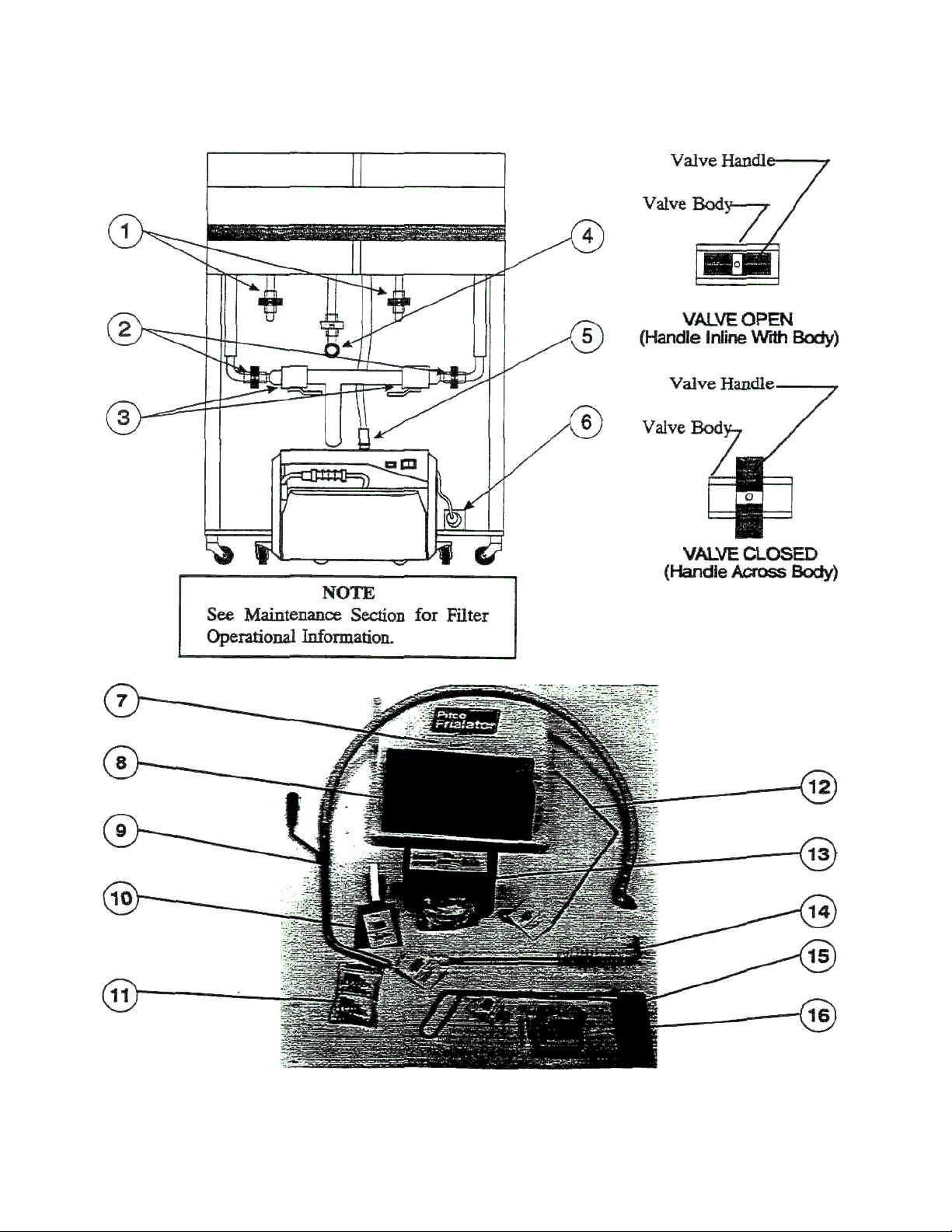
Figure 1 Fryer Illustrating Filter Components, Tools, and Accessories
-1-
Page 5

SHORTENING FILTER PROCEDURES
This section describes the procedures to be used to filter fryers using the UFM filter system. Figure l is
provided to show the locations of the components used in the filter process. The callouts in Figure 1 point
to the components and accessories discussed in the filter procedure. The components and accessories are
described below. The illustrations used with the filter procedures are provided to show where the oil is
going and which valves are open. Frequent filtering of your shortening will prolong the shortening's
usable life. Daily shortening filtering is strongly recommended.
(1) Return Valve(s) RED - When open, with the filter
pump on, allows the shortening to return to the fryer
tank.
9) Flush Hose (OPTIONAL) - Attached to the filter
piping (4), this hose and nozzle is used to flash out the
fryer tank. This hose is an optional item.
(2) Circulation Valve(s) BLUE -When open, with the
filter pump, on, circulates the shortening from the filter
pan through the drain pipe and back to the filter pan.
Circulating the oil polishes the oil and clears the drain
piping.
(3) Drain Valve(s) GREEN - Drain the oil from the
fryer tanks to the filter pan.
(4) Flush Hose Connection YELLOW - Quick
disconnect and valve for optional flush hose.
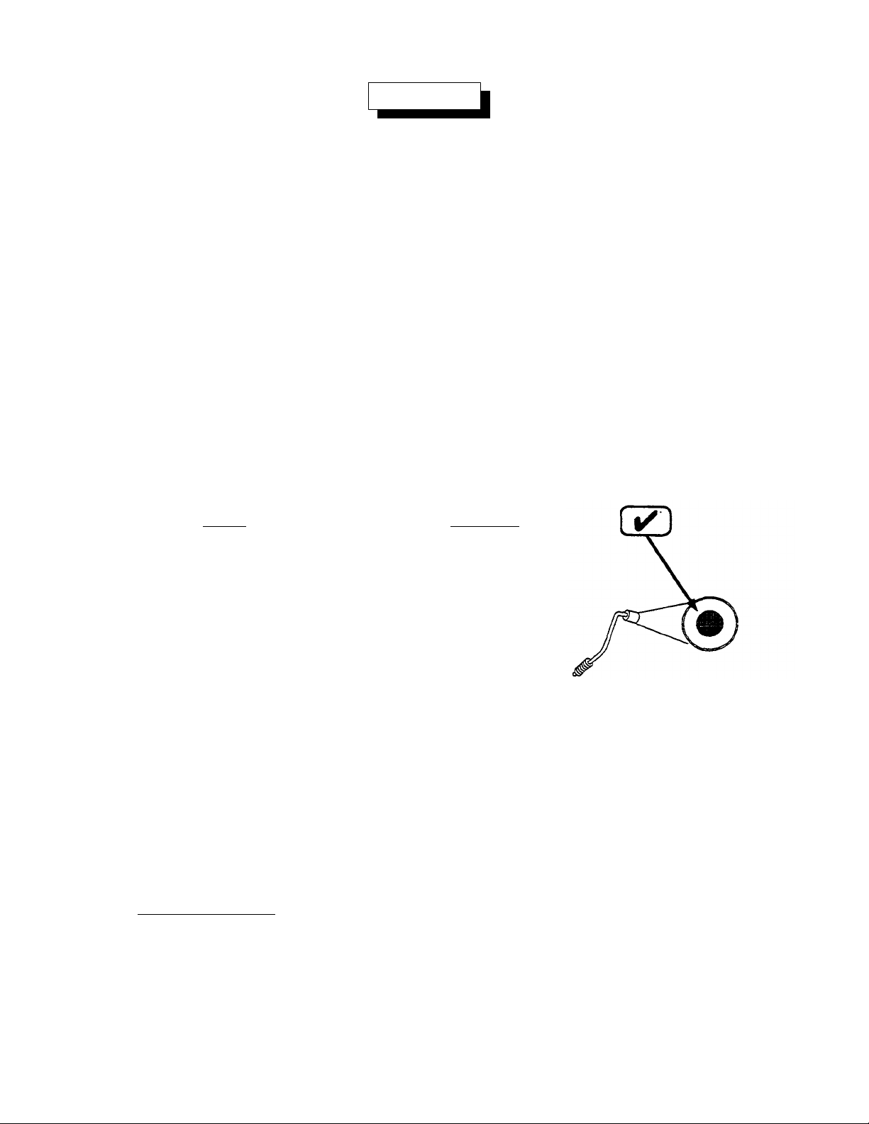
(5) Oil Return Connection - Quick disconnect for
return oil from the filter unit to the fryer. Simply push
down on fitting to connect Lift up lower black collar to
disconnect
(6) Filter Unit Cord - Provides electrical power to the
filter unit
(7) Filter Paper-Package of pre-cut filter paper.
(8) Filter Crumb Catch - Mounts in the filter pan and
catches large debris during filtering.
(10) Filter Crumb Scoop - Short handle wide pan
design this scoop is used to remove the debris from the
filter pan.
(11) Cleaner - Used daring fryer boil-out cleaning.
(12) Drain Clean Out Rod - Long handled design. This
tool is used to clean out the drain openings.
(13) Precoat Filter Aid- Coarse Diatomaceous earth
used to enhance the filter ability of the filter media.
(14) Cleaning Brush - This long handled stiff bristle
brush is used to brush down the crumbs inside the fryer
tank during shortening filtering.
(15) Fryer Crumb Scoop - A specially designed long
handle scoop for scooping out the fryer. The scoop
section is narrow enough to fit down between the fryer
burner tubes.
(16) Precoat Measuring Cup - Marked in ounces for
correctly measuring precoat to be added to the shortening prior to filtering.
-2-
Page 6
WARNING
At operating temperature the shortening temperature will be greater than 300°F.
Extreme care should be used when filtering operating temperature shortening to
avoid personal injury.
GENERAL FILTER HINTS
1. Ensure that all oil in the filter pan is returned to the fryer before it cools and hardens. This is very
important if you are using solid shortening.
2. Always use a Pitco Precoat ® for fastest filtrations, maximum labor saving, and cleanest/
clearest possible shortening. Impaired filter performance will result without the use of a filter
aid.
3. The longevity of your oil is related to how clean you keep it With a Pitco built in system, it is
easy to do a quick drain/refill anytime. By removing suspended particles often it prevents mem
from burning.
4. When the time it takes to refill the fryer after filtering exceeds the time shown below, scrape me
filter bag. If scraping does not bring the refill time back down change the filter paper as
described in this supplement.
Model Refill Time
7 2:00 Minutes
14 (all models) 3:00 Minutes
18 5:00 Minutes
4a. Your filter pump is protected from clogging by a special
screen in the pickup tub. Clean this screen each time a
new filter is installed (see illustration on page 8 step f.
5. If you have filter system problems, refer to the troubleshooting procedures later in this manual.
6. Always check to ensure that the black quick disconnect (oil return line) is completely engaged
before filtering. When connecting the quick disconnect, you will feel a definite snap and hear a
click when the connection is made. After connecting the hose gently pull on the connection to
make sure that it is connected.
7. The filter power MUST be plugged into the fryer at all times.
8. Purge the filter lines by allowing the filter pump to run for 15 seconds after air bubbles are seen
inside the fryer tank.
9. Rush Hose (Optional) - If your fryer has a flush hose allow it to drain completely before storing.
-3-
Page 7
FILTER PROCEDURES (Numbers in parenthesis refer to Figure 1 unless otherwise noted)
NEVER
• Run the filter system without a filter bag/paper.
• Attempt to filter more than one fryer tank at a time.
• Empty the oil from the fryer before turning OFF the frye r burners.
• Store the UFM Filter Unit anywhere other than in the
fryer filter cavity.
a. Disconnect the filter pan, slide it out and empty the
crumb basket. Scrape previously filtered residue off
the filter paper. Examine the filter bag for dark,
scuffed, or torn areas. Refer to Filter Media Replacement for filter bag replacement. Re-install the pan.
b. Turn the fryer OFF (See Standby Shutdown). Re
move the baskets from the fryer tank(s). Use the clean
out rod (12) to lift out the tube screens. If there are
excess crumbs in the fryer tank, remove them with the fryer crumb scoop (15).
c. If you have replaced or scraped the filter paper, stir in Precoat Filter Aid (13) to the shortening in
fryer (if you are using a filter aid other than Pitco, follow that products instructions for proper
amounts). After cleaning out the excess debris with the fryer scoop (15) sprinkle the powder into
the first fryer to be filtered and stir the powder into the oil.
d. Check the drain spout to ensure that it is aimed into the filter pan.
NOTICE
Always open a system valve before
starting the filter pump.
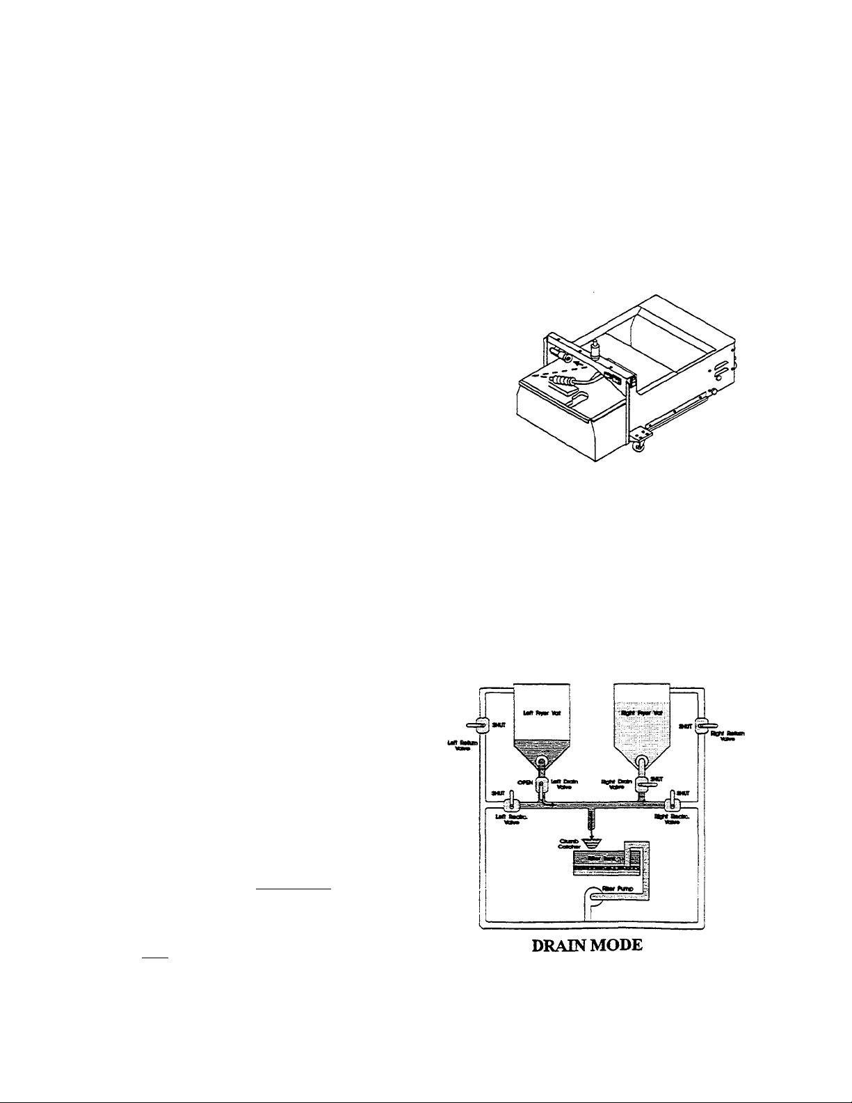
e. Slowly open the green handled drain valve
(3) for the tank being filtered. If necessary
use the clean-out rod (12) to clear the
crumbs from the drain. Use the long handled
brush (14) to clean the sides of the tank as
the oil drains. If you have the optional flush
hose (9) go to step i.
CAUTION
The filter tank can only hold the oil from
one fryer. DO NOT try to filter more than one
tank at a time.
-4-
Page 8
NEVER turn on the filter pump unless the PREHEAT FINISHED light (Figure 2, item 3) is on.
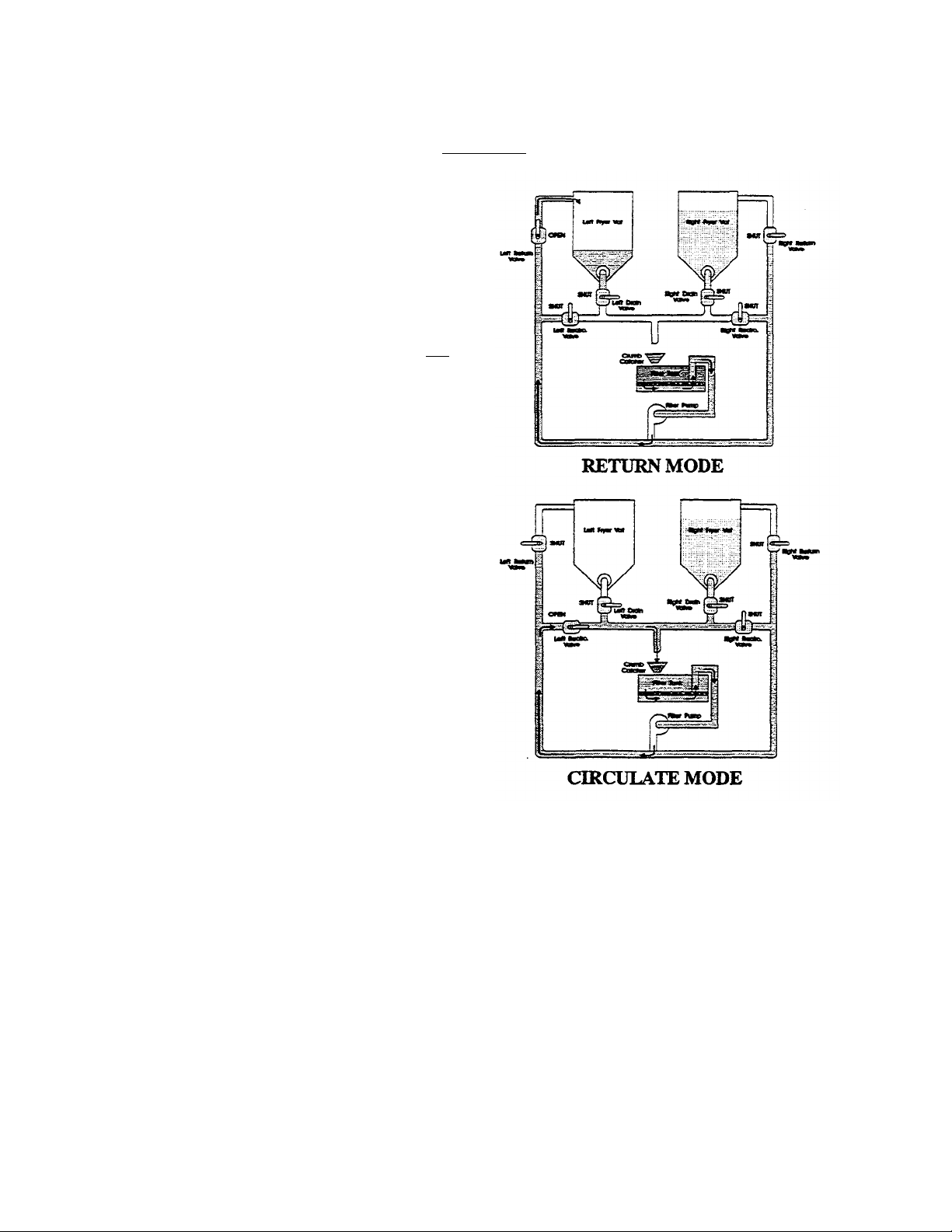
f. Open the red handled return valve (1) to the
tank you are filtering. When the tank is
empty close the green drain valve (3) and
turn on the filter pump. As the tank fills
brush the inside of the tank to remove
crumbs.
g. When bubbles are seen coming out of the
oil return spout turn off the pump. Open the
green handled drain valve (3) and allow the
tank to drain again. Repeat steps b through
d until the tank is clean.
h. When the tank is clean, drain the shortening
by opening the green handled drain valve
(3). Ensure the red handled return valve (1)
is shut and open the blue circulating valve
(2). Start the pump and allow the
shortening to circulate for approximately 2
minutes. This will polish the shortening
and clean out the filter lines.
CAUTION
i. OPTIONAL FLUSH HOSE (9) - Connect
the flush hose to the quick disconnect (4).
Direct the flush hose nozzle into
the tank being filtered. Open the green handled drain valve (3), the yellow handled flush hose
valve, and start the pump. Continue to rinse until all the debris has been removed from the tank.
Turn off the pump and allow the tank to drain to the filter. Close the yellow handled flush valve
and disconnect the flush hose.
j. Turn the pump off, close the blue handled circulating valve (2), and replace the tube screen.
Open the red handled return valve (1) and turn on the pump to refill the fryer with the filtered
oil. Continue to run the filter pump until bubbles come out the oil return opening. Turn the
pump off and close the red handled return valve (1). If necessary add more shortening to the
tank to return the shortening level to the fill mark. The fryer is ready for use.
-5-
Page 9

WARNING
WARNING
k. If you are using solid shortening, open the blue handled recirculating valve. if the fryer is
equipped with a flush hose, open the yellow handled flush hose valve (with the hose attached).
Allow the oil in the filter lines to drain to the filter pan, turn on the pump for one minute. After
the lines are drained, close the recirculating valve (2) and the flush hose valve.
OWNER MAINTENANCE AND ADJUSTMENTS
This section provides you with the information and procedures necessary to perform basic fryer
maintenance and adjustments. If after performing maintenance on your fryer it does not perform properly,
contact your authorized service center.
The power supply must be disconnected before servicing or cleaning the appliance.
Filter Media Replacement
At operating temperature, the shortening in the fryer may be hotter than 375°F
(190°C). This hot, melted shortening can cause severe burns. Do not let the hot
shortening touch your skin or clothing. Always wear insulated oil-proof gloves
when working on the filter system.
This section describes the filter systems components and details the procedures necessary to replace
the filter media.
-6-
Page 10

UFM Filter System
The UFM filter module, also referred to as the Spacefighter filter module, stores neatly under the fryer when
not in use. The unit is designed for easy movement to allow one UFM filter to be used on several fryers. An
automatic internal heating system keeps the filter module lines clear of shortening to ensure smooth oil flow.
A Preheat Finished light indicates when the heating system has heated the oil lines to the proper temperature.
The filter module is shown in Figure 2 with specific components and features called out and briefly described.
Figure 2 UFM Filter Module
(1) Filter Pan - Holds the oil from the fry tank. (6) Filter Unit Quick Disconnect - Quick disconnect
that connects the filter unit to the fryer.
(2) Pump Switch - Two position switch used to torn
the filter pump ON/OFF. (7) Pomp Motor Thermal Overload - (Behind
cover) Protects motor from high temperatures. Trips
(3) Preheat finished Indicator - Lights to indicate
that the filter lines are wanned to filtering tempera
ture. (8) Circuit Breaker - Generally left ON. Will trip if
(4) Pick -Up Tube - Connects filter envelope assem
bly to piping. Incorporates a strainer to protect filter
pump from grit in the event of envelope failure.
(5) Filter Assembly Connector - An insulated
handle covers the filter pan assembly connection. (9) Power Supply Cord • Plugs into fryer receptacle
This connection separates the filterpick -up assembly
from the filter piping for removing the filter pan for
cleaning.
if the pump motor is near over heating.
overload occurs, i.e. pump is turned on but no system
valves are open. To reset, find and correct cause of
trip. Tumpowerswitch(3) OFF. Push circuit breaker
OFF, then return it to ON. Normal operation will
resume.
to provide power for filter operation.
-7-
Page 11

WARNING
Follow the procedures below to change the UFM filter bag.
It will be easier and safer if the filter assembly has cooled to room temperature
before handling any filter parts.
a. A unique design allows for paper replacement without the need to disconnect the filter unit from
the fryer.
b. To remove the filter pan, disconnect
the filter tube connection. This is done
by sliding the insulated portion (1) of
the connector out of the receiving
portion of the connector.
c. Grasp the filter pan handle and gently
pull the assembly toward the front of
the filter unit (2). When the pan is
clear of me filter unit, remove the filter
pan cover.
d. Remove the crumb catch tray from the
front of the filter pan. Discard any
debris that may be in the crumb
catch.
e. Lift up on the filter paper assembly
and remove from the filter pan. Unscrew the suction tube from the
filter paper support rack. Remove
the clip screen and slide me filter
paper support rack assembly out of
the filter bag.
f. All of the filter pick up assembly
parts can be washed in a dish
washer or a pot sink.
f1. Flush out the suction tube assembly
with hot water. The pick up tube
screen keeps grit and solid material
from binding the pump. After
flushing the pick up tube screen
check to ensure that the screen is
free of debris. After cleaning, it is
very important to thoroughly dry
the parts before re-assembling. Water and oil do not mix. Water in hot oil will
cause the oil to splatter.
g. Start re-assembling the filter pick up assembly by sliding the new filter paper on
to the filter paper support rack. Ensure that the hole in me filter paper goes over
the pick up tube assembly threaded connector.
-8-
Page 12

h. Fold the open end of the bag in two folds.
The first fold should be approximately 1
inch from the end and the second should
be over the edge of the rack assembly.
i. Slide the clip screen over the folded
end of the filter paper. Ensure the opening of the clip
screen goes over the pick up tube connection. Screw
the suction tube assembly onto the threaded connection.
j. Place the filter rack assembly in the filter pan and
install the crumb catch tray in the front of the filter pan.
k. Slide the filter pan assembly back into the filter unit and attach the pick up tube connector to the
filter unit connection.
USING THE UFM MODULE AS A PORTABLE FILTER
The UFM filter system when used with the filter unit flush hose part # B6623201 can be moved around the
kitchen to filter individual fryers. To filter other fryers follow the procedure below:
a. Unplug the power cord from the fryer and
disconnect the quick disconnect from the
top of the filter unit.
b. Move the filter unit to the appliance to be
filtered. Attach the flush hose to the filter
unit quick disconnect Plug the filter unit
cord into a three prong (grounded) outlet
using a 3 prong (grounding) 14 AWG
extension cord.
c. Remove the filter pan lid and direct the
applian ce oil drain into the crumb catch.
Use a drain extension connected to me
fryer drain valve to allow the drain to extend over the filter pan. Be sure to wait for the Preheat
Finished light to come on before turning on the pump.
d. When finished filtering, disconnect the flush hose and empty it into a fryer. Hang the hose,
nozzle down, to drain.
-9-
Page 13

TROUBLESHOOTING
serted in
the receptacle so that the white
that the black insulator is
pushed all the way down and locks on
The following table will help you diagnose and solve the majority of filter problems without having to call
service. Most problems are caused by improper operation or maintenance and are easily corrected. If the
steps below do not return your filter to proper operation, call Pitco Technical Service for additional help,
1-800-258-3708
Typical problems encountered are:
1. Filter will not pump.
a. Pump sound can not be heard.
b. Pump sound can be heard.
2. Filter pumps slowly.
3. Filter leaves excessive amount of oil in pan.
4. "PREHEAT FINISHED" light does not come on.
5. Filter circuit breaker or motor thermal protector opens frequently.
PROBLEM POSSIBLE CAUSE SOLUTION
NOT PUMPING 1. Filter or fryer not Check all electrical connections.
(Pump sound can not be plugged in.
heard.)
2. Filter circuit breaker Reset circuit breaker, check that a
"OFF" or tripped. system valve is open before start
ing pump. Figure 2, Item 8
3. Thermal protector on
Allow motor to cool, reset thermal
motor is open. protector. (If this is a recurring
problem, me people doing the fil-
tering must be taught to open a blue
or red valve first, then switch the
pump "ON"). Figure 2, Item 7
Check that the pickup tube is in
insulators touch one another.
Figure 2, Item 5
Be sure
the filter fitting. Figure 2, Item 6
NOT PUMPING
(Pump sound can be heard.)
1. Filter pick up not attached
correctly.
2. Return hose not fully engaged
on filter fitting.
-10-
Page 14

PROBLEM POSSIBLE CAUSE SOLUTION
Screen inside pick up tube
is clogged with debris.
(Usually from a tear in the
ISHED" light is on before turning
pump switch "ON". See "Early
Clean out the screen inside the pick
up tube connector nut. Doing this
each time a new paper is put on will
save problems during filtering.
3. System plugged with
Wait until the "PREHEAT FIN-
hardened shortening
Morning Filtration".
NOT PUMPING (Cont.)
(Pump sound can be heard.)
4.
filter enve lope.)
Figure 3, Item 9
Early Morning Filtration - dog free filtering can be assured even with solid shortening, if a few basic
practices are followed.
1. Make certain that the filter is plugged into the fryer electrical receptacle and that the filter circuit
breaker is "ON".
2. Turn on the fryer and heat the oil to cooking temperature. Allow the fryer to operate for 45 minutes
before attempting to filter.
3. Be certain the "PREHEAT FINISHED" light is on.
4. It may be necessary to use the drain clean-out rod to clear the drain passage of solid shortening for
the oil to drain. (This is proof that the fryer's cold zone is working!)
PROBLEM POSSIBLE CAUSE SOLUTION
PUMPS SLOWLY
Pumps Slowly - The filter (with a clean bag, pumping clean oil at 350°F) should refill the fryer to the
"MIN" line in the following times:
Model 7, E7 1 Minutes 30 Seconds (1:55 Export)
Model 14, E14 1 Minutes 50 Seconds (2:10 Export)
Model 14R (Gas) 2 Minutes 05 Seconds (2:25 Export)
Model 18, E18 3 Minutes 00 Seconds (3:30 Export)
1. Sediment to deep. Scrape sediment from top of pick
Clogged filter paper.
2.
(Scraping does not help.)
3. Not using filter aid.
up.
Change filter paper when refill time
exceeds the values shown in the "Filter
Hints" section.
Use Filter aid to prevent fine food
particles from blocking the paper
prematurely.
-11-
Page 15

PROBLEM POSSIBLE CAUSE SOLUTION
if torn.
Clean out the screen inside the pick
up tube connector nut. Doing this
each time a new paper is put on will
save problems during filte ring.
PUMPS SLOWLY (Contin ued)
4. Pick up screen is
clogged.
Figure 3, Item 9
Buy and use only GENUINE Pitco
5. Not Using Approved
Filter Paper
filter paper for best results. Pitco
Part No. PP10613
Filter Leaves Oil In The Pan
NOTE
The filter will leave about a cup of oil in the pan and filter envelope, this is normal. The oil in
the pan is only lost when a new paper is installed.
PROBLEM POSSIBLE CAUSE SOLUTION
FILTER LEAVES EXCES 1. Excessive sediment Scrape the sediment layer down to
SIVE AMOUNT OF OIL IN buildup. the metal scraping screen.
PAN.
2. The pickup tube is not Once the pan is empty, tighten the
nut firmly against the sediment
tightened firmly against
the scraping screen.
screen.
3. There is a hole in the Inspect the filter bag for tears, some-
filter bag. times a torn bag will cause a "hiss
ing" sound as air leaks in. Change
"PREHEAT FINISHED" LIGHT
DOES NOT COME ON.
1. Not plugged into electricity.
Figure 2, Item 9
2. Filter ci rcuit breaker
"OFF". Figure 2, Item
7
3. Insufficient time al lowed for
heater to
work.
-12-
Check that the filter is plugged into
fryer. Also, make sure that fryer is
getting power.
Check that filter circuit breaker is
in "ON" position.
If the filter is disconnected from
line voltage or the filter circuit breaker is
turned "OFF" for more
than 2 hours, it may take the heater 10-
12 minutes to turn the PRE
HEAT FINISHED light on after power is
restored.
Page 16

PROBLEM POSSIBLE CAUSE SOLUTION
circuit breaker.
FILTER CIRCUIT
BREAKER TRIPS FRE-
QUENTLY Figure 2, Item 8
1. Turning pump on be
fore opening a system
valve first.
Open the desired valve first, then
turn the pump on. Starting the
pump without opening a valve
causes an overload that open the
2. The blackhose connector is not filly engaged.
Make sure that the hose is fully
engaged on the filter fitting. The hose
has a valve in it that will not open
until the hose snaps into place.
3. Solid shortening is blocking
the pump discharge line.
Wait until the "PREHEAT FINISHED" light is on before turning
pump switch "ON". Allow the fryer to
operate for 45 minutes after reaching
cooking temperature.
The circuit breaker is designed to protect against electrical overload. If you are certain that the filter is
being operated properly, you should discontinue using the filter and call Pitco Technical Service for
assistance. 1-800-258-3708
THE PUMP MOTOR THERMAL PROTECTOR TRIPS
FREQUENTLY Figure 2,
Item 7
1. The filter has been used
to filter one or more
fryers and me pump has
been turned on without
a system valve open.
2. The filter has been used
to filter one or more
fryers and the black
hose has been discon-
Open the desired valve first, then
turn the pump on. Starting the
pump without opening a system
valve will cause an overload and
trip the circuit breaker.
Make sure that the hose is fully
engaged on the filter fitting. The
hose has a valve in it that will not
open until the hose snaps into place.
nected and improperly
reconnected.
-13-
Page 17

PROBLEM POSSIBLE CAUSE SOLUTION
3. The filter has been used
THE PUMP MOTOR
THERMAL PROTECTOR
TRIPS FREQUENTLY
Figure 2, Item 7
The filter pump motor thermal overload protector protects your filter motor from permanent
damage by overheating. The thermal overload will not trip under normal filtering conditions
but will trip if the filter pump is started with the pressure side blocked, i.e.: the hose is not
connected, a system valve is not open or the hot filter is installed in a fryer mat has not been
properly heated up.
to filter one or more
fryers and then trans ferred to a fryer that is
not properly warmed
up.
NOTE
Always allow a fryer to operate for
45 minutes after reaching cooking
temperature before attempting to
filter it.
-14-
Page 18

REPLACEMENT PARTS
Replacement parts for the filter unit are available through fee local ASAP- Call Pitco Frialator technical
service at 1-800-258-3708 for information on your nearest ASAP agent. The index numbers in Table 1
refer to Figure 1, Fryer Illustrating Filter Components, Tools, and Accessories. The illustrations at the end
of this section are provided to show relative location of components of the filter. The illustrations have
numbered lines (tag lines) pointing to components. With each illustration there is a table of components in
numerical order by illustration tag number.
Table 1 Filter Tools and Accessories
INDEX
NUMBER PART DESCRIPTION NUMBER UNIT
7 FILTER PAPER, 18-1/2" X 20-1/2° HEAVY DUTY PP10613 25
8 Filter Crumb Catch B6621202 1
9 FLUSH HOSE, 60" (Connects Directly to Filter) B6623201 1
10 FILTER CRUMB SCOOP B7404801 1
11 Cleaner P6071397 1
12 DRAIN CLEAN OUT ROD A3301001 1
13 PRECOAT® FILTER AID (1 BOX, 120 PACKS) PP10753 1 BX
14 FRYER CLEANING BRUSH PP10056 1
15 FRYER CRUMB SCOOP B7490701 1
16 Precoat Measuring Cup P6071368 1
PART QTY/
-15-
Page 19

Table 2 Filter, Pick-Up/Pan Assembly
1 B6621001
Filter Pan, Weldment (SF50A)
1
Item
Number
2 B6620001 Filter, Rack 1
3 B6617001 Filter, Screen Clip 1
4 B6621202 Filter, Catch Crumb, Weldment 1
5 A6056001 Label, Filter Instruction - Pan 1
6 B6621301 Filter, Cover Pan, Weldment (SF50A) 1
7 P6071516 Handle, Door, 3" C to C 1
8 A6681802 Filter, Coupling Top 1
9 B6615301 Filter, Screen Inlet 1
10 PP10409 O-Ring Viton 11/16" x .094" W 1
11 B6621601 Filter, Tube Suction, Weldment 1
12 PP10629 Ring, Retaining - Internal .875" 1
13 A6684601 Filter, Insulation Pick-Up 1
14 P0062100 Screw, 1/4-20 x 3/8" Set 2
15 P0007300 Screw, 8-32 x 1/4" Hex & N 2N 2
16 PP10613 Filter Paper, 18-1/2" x 20-1/2" Heavy Duty 1
Pitco Frialator
Part Number
B6621002 Filter Pan, Weldment (SF65A) 1
B6621302 Filter, Cover Pan, Weldment (SF65A) 1
Description
Revised 5/28/93
Quantity Per
Unit
-16-
Page 20

Figure 3 Filter, Pick-Up/Pan Assembly
-17-
Page 21

Table 3 Filter, Frame/Electrical Assembly (Portable)
1
Item
Number
1
Pitco Frialator
Part Number
B6621101
Description
Filter Frame, Weldment (SF50A)
B6621102 Filter Frame, Weldment (SF65A) 1
2 A6683002 Filter, Cover Motor (SF50A) 1
A6684102 Filter, Cover Motor (SF65A) 1
3 A6685702 Filter, Bracket Mounting Cover 1
4 A6684402 Filter, Cover Tubing (SF50A) 1
A6684404 Filter, Cover Tubing (SF65A) 1
5 A6684502 Filter, Cover Tubing Cap 1
6 PP10741 Filter, QD SNP 23 Nipple 1
7 A6683802 Filter, Guard Tubing Channel 1
8 A6683102 Filter, Panel, Switch 1
9 PP10331 Lamp, 125V Green Rectangular 1
10 PP10735 Switch, Rocker DPST 15A, with Breaker 1
11 A6055801 Label, Overlay Filter Module 1
12 A7680402 Plate, Switch Pasta 1
13 A6683302 Filter, Box Electrical Body 1
14 P6071062 Caster, 2" With Top Plate 4
15 P0011300 Screw, 10-24 x 3/8" Indent Hex 16
16 PP10176 Nut, Center Lock 10-24 16
17 PP10147 Clip. Cable 0.375 ID 2
18 PP10107 Bushing, Strain Relief 1
19 B6717901 Wiring, Cord, Filter with Termination 1
20 P0093300 Nut, Hex (KEP) 1/4-20 ZN 5
21 A6682802 Filter, Guide Cable (SF50A) 1
A6682804 Filter, Guide Cable (SF65A) 1
22 B6717101 Wiring, Cable Filter Assembly (SF50A) 1
B6717102 Wiring, Cable Filter Assembly (SF65A) 1
23 PP10192 Bushing, Strain Relief 90 2
24 PP10460 Switch, Rocker Circuit Breaker SPST 8A 125V 1
25 PP10119 Label, Warning Motor Reset 1
26 P6071490 Plug, Hole 7/8" Plated 2
27 PP10692 Screw, 10-24 x 5/16" TH Phillips ZN 5
28 PP10752 Screw, 10-32 x 1/2" Thread Roller 18
29 P0000100 Screw, 6-32 x 7/8" RH ZN 2
30 P009100 Nut, Hex 6-32 ZN (KEP) 2
31 P0075200 Screw, TEK 2 #8 x 1/2" SLF DR 1
32 P6071497 Plug, Hole 3/4" Plated 1
33 B6622301 Hose Assembly With Quick Disconnect 1
33a B6622001 Filter Hose UFM Except RPB 1
B6622002 Filter Hose UFM for RPB 1
33b B6622801 Filter Return Insulation Disconnect 1
33c A6685401 Filter, Insulator Top 1
-18-
Quantity Per
Unit
Revised 5/28/93
Page 22

Firgure 4 Filter, Frame/Electrical Assembly (Portable)
-19-
Page 23

Table 4 Filter, Motor / Return Assembly
Part Number
Unit 1 PP10101
Pump/Motor
1/3
HP, 115/230V, 50/60Hz
1
Item Number
2 PP10106 Fitting, Elbow Male 90 50D x 5 NPT 2
3 A6682702 Filter, Tubing Out SS (SF50A) 1
4 PP10731 Fitting, Elbow Male 90 50D x 375 NPT 1
5 B6621401 Filter, Tubing Pump - Inlet Weldment (SF50A) 1
6 PP10039 Heat Tape, 1/2" x 79" 110V 165 Watt 1
7 PP10111 0-Ring, Viton 50ID x .688 x .094W 2
8 A6685601 Filter, Insulator 0-Ring Fitting 1
9 P0062100 Screw, 1/4-20 x 3/8" Set 1
10 B6717701 Wiring, Motor Harness 1
11 PP10739 Thermostat, Snap Disc 1
12 PP10687 Screw, 6-32 x 5/16" TH Phillips ZN 2
13 P009110 Nut, Hex (KEP) 6-32 ZN 2
14 PP10738
15 P0144000 Nut, Hex 5/16"-18 SST 2
16 P0115000 Screw, 5/16" -18 x 3/4" HHC SSBB 3
Pitco Frialator
A6683702 Filter, Tubing Out SS (SF65A) 1
B6621402 Filter, Tubing Pump - Inlet Weldment (SF65A) 1
Nut, Retaining Clip 5/16" -18
Description
Quantity Per
Revised 5/28/93
1
-20-
Page 24

Figure 5 Filter, Motor/Return Assembly
-21-
 Loading...