

Page 1
SERVICE SECTION
Service, Parts, and Schematics
For Gas Fryers With Solo Filter
Models:
SF14 UFM & SF14R UFM
Pitco Frialator, Inc., P.O. Box 501, Concord, NH 03302-0501 • 509 Route 3A, Bow, NH 03304
(800) 258-3708 * (603) 225-6684 • FAX (603) 225-8497 A
BLODGETT Company
Page 2

Table of Contents (Service)
413 Replacin
g the Heat Baffles
4-1
416 Thermopile Replacement
4-4
42 TROUBLESHOOTING PILOT LIGHTS
4-7
43 TROUBLESHOOTING FRYERS WITH UNITROL VALVES
4-8
Section
Table of Contents (Service) i
List of Figures ii
Chapter 4: Service
41 REPLACEMENT PROCEDURES 4-1
411 Main Burner Removal and Replacement 4-1
412 Changing the Main Burner Orifice 4-1
414 Pilot Burner Removal and Replacement 4-2
415 Pilot Orifice Replacement 4-2
4151 Pilot Flame Adjustment 4-2
417 Thermostat Replacement 4-4
418 Limit Control Replacement 4-5
419 Calibrating the GS Thermostat 4-6
44 TROUBLESHOOTING FILTER UNITS 4-10
Chapter 5: Parts
Title Page
4-1
5-1
Chapter 6: Schematics
ALPHABETICAL PART LIST 5-6
NUMERICAL PART LIST 5-9
6-1
i
Page 3

List of Figures and Tables
Figure No Title Page
5-1
5-2 Filter Pan Assembly 5-5
Table No
5-1
5-2 Filter Pan Assembly 5-4
Overall Exploded View
Overall Exploded View
5-3
Title Page
5-2
ii
Page 4

Chapter 4: Service
This chapter provides the qualified technician with the replacement and troubleshooting procedures
necessary to service the Pitco fryer.
4.1 REPLACEMENT PROCEDURES
These procedures are provided to the qualified technician as a guide to removal and replacement of
various fryer components. If a test is required to verify component operation after installation, it
will be referenced.
WARNING
To prevent bums, always ensure the fryer is completely SHUT DOWN and
COOLED down before working on the fryer. Do not break any fryer gas
connections while the unit is connected to a gas supply line.
WARNING
The power supply must be disconnected before servicing or cleaning the
appliance.
4.1.1 Main Burner Removal and Replacement
a. Loosen the set screw in the base of the burner casing.
b. Unscrew and remove the two hex head screws at the top of the burner.
c. Loosen the set screw on the air collar. Lift the burner and air collar up to clear the top of
the burner fitting. Remove the burner from the fryer.
d. To re-install the burner, reverse the procedure.
4.1.2 Changing the Main Burner Orifice
a. Unscrew the orifice with a 3/8" wrench and remove the orifice.
b. Insert the new orifice and tighten with the 3/8" wrench. Ensure the orifice is tight
enough to prevent gas leakage around the orifice.
4.1.3 Replacing the Heat Baffles
a. Remove the Main Burner as described in 4.1.1.
4-1
Page 5

b. The heat baffles are located inside the heat tubes. They are attached to the rear of the
baffle supported by tack welds. Using a chisel, break away the baffle support and
remove the old baffles. Be careful not to puncture the heat tubes because this will require
complete tank replacement.
c. Insert the new baffles in the tubes in the original position. The new baffles sit in position
and do not require welding.
d. Install the main burners.
4.1.4 Pilot Burner Removal and Replacement
a. Unscrew the tubing nut from the pilot tubing connection at the gas valve. Disconnect the
thermopile from the connection on the gas valve.
b. Unscrew and remove the two screws that attach the pilot assembly to the fryer tank. Lift
the entire pilot assembly out of the fryer.
c. To replace the pilot assembly, reverse the procedure.
4.1.5 Pilot Orifice Replacement
a. Remove the pilot assembly as described in 4.1.4.
b. Unscrew the tubing nut from the pilot tubing connection at base of the pilot burner. The
pilot orifice is located inside the tubing connection.
c. Remove the orifice and replace with the new orifice. Ensure the orifice is tight enough to
prevent gas leakage around the orifice.
d. Replace the tubing nut in the pilot tubing connection and tighten enough to prevent gas
leakage.
e. Replace the pilot assembly and adjust the pilot flame as described below.
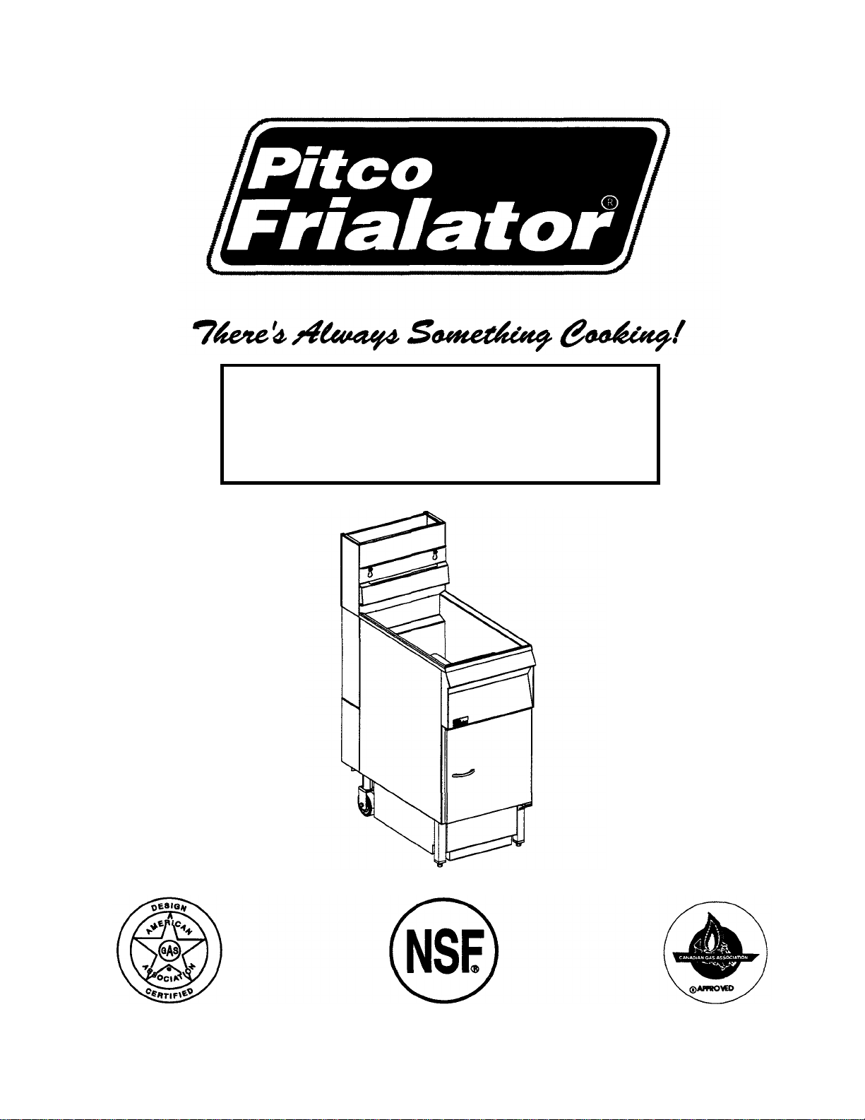
4.1.5.1 Pilot Flame Adjustment - The pilot flame should be adjusted to produce the proper millivolt
output from the pilot sensing device. Millivolt output for the thermopile should be between 300 and
500 millivolts. Figure 4-1 shows the pilot assembly with examples of the incorrect and correct pilot
size. Example A illustrates a pilot flame size that is too small to produce sufficient millivolt output.
Example B is the correct size for proper millivolt output.
4-2
Page 6
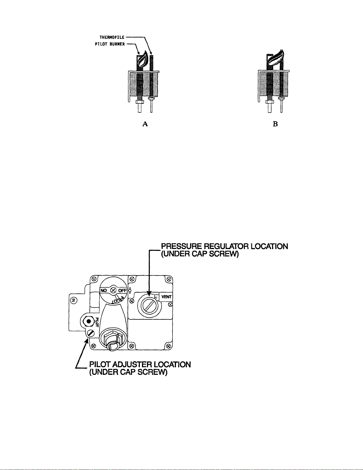
Figure 4-1 Pilot Assembly, Flame Adjustment
a. This test requires a DC millivolt meter set to a scale of 0-l000mv.
b. Locate the thermopile wires coming from the thermostat/High Limit box going to the
gas shut off valve. The wire insulation size decreases near the gas valve connections.
c. Connect the negative (-) test probe to pilot bracket.
d. Connect the positive (+) test probe to one of the High Limit terminal connections
e. Remove the pilot flame adjustment cover.
Figure 4-2 Gas Valve Showing Location of the Pressure Regulator and Pilot Adjusters
f. Turning the flame adjusting screw clockwise lowers the flame and the millivolt output.
Turning the screw counterclockwise increases flame size and millivolt output.
4-3
Page 7

g. Rotate the screw in the direction to achieve a reading of 400 ±50 mv for thermopiles.
NOTICE
Allow 3 to 5 minutes between flame adjustments to allow the reading to settle.
h. Replace the pilot flame adjusting screw cover.
4.1.6 Thermopile Replacement
a. Remove the pilot assembly as described in 4.1.4.
b. Unscrew and remove the thermopile from the pilot assembly.
c. Remove from gas valve magnet.
d. Insert the new thermopile in the pilot assembly.
e. Replace the pilot assembly and adjust the pilot flame as described in 4.1.5.1.
4.1.7 Thermostat Replacement
The thermostat includes the temperature adjustment knob, temperature sensor inside the fryer tank,
and connecting capillary tubing. The high limit control also has a temperature sensor in the fryer
tank, so ensure you are removing the correct temperature sensor.
CAUTION
Thermostat capillary tubing is very delicate. Be VERY CAREFUL when
working with the capillary tubing. If the tubing is kinked or broken the
thermostat is no longer usable.
a. Drain the oil from the fryer and remove the heat tube screens. The thermostat probe (heat
sensor) is clamped to the heat tube inside the tank. Unscrew and remove the two screws in
the thermostat probe clamp.
b. Remove the thermostat probe from the clamp and straighten the capillary tubing. Unscrew
the small hex nut inside the cabinet under the tank for the thermostat control.
c. Unscrew the large connector nut from the tank and pull the thermostat probe and capillary
tubes through the opening.
d. Pull the knob off of the thermostat. Remove the two slot head screws from the retaining
plate.
4-4
Page 8

e. Remove the two hex head screws that hold the thermostat control unit in the fryer cabinet.
f. Remove the tubing from the fittings on the thermostat body. Remove the defective thermostat
control unit from the fryer.
g. Install the new thermostat following the above procedures in reverse order. Remember to be
careful with the capillary tubes.
h. Use appropriate pipe joint compound on the large fitting before installing to prevent oil leakage.
DO NOT use joint compound on the small nut.
i. Perform the calibration procedures detailed in section 4.1.9.
4.1.8 Limit Control Replacement
The limit control includes a temperature sensor inside the fryer tank, control unit inside the fryer cabinet,
and connecting capillary tubing. The high limit control temperature sensor looks like the thermostat
temperature sensor, so ensure you are removing the correct temperature sensor clamp.
CAUTION
The limit control capillary tubing is very delicate. Be VERY CAREFUL when
working with the capillary tubing. If the tubing is kinked or broken the limit control
is no longer usable.
a. Drain the oil from the fryer and remove the heat tube screens.
b. The limit control probe (heat sensor) is clamped to the heat tube inside the tank. Unscrew and
remove the two screws in the probe clamp.
c. Remove the probe from the clamp and straighten the capillary tubing. Unscrew the small hex nut
inside the cabinet at the bottom of the tank for the limit control.
d. Unscrew the large connector nut from the tank and pull the pr obe and capillary tubes through the
opening.
e. Remove the two mounting screws from the limit control bracket and remove the limit control
unit. Disconnect the wires from the limit control box.
f. Reverse the procedure to install the new limit control.
g. Use appropriate pipe joint compound on the large fitting before installing to prevent oil leakage.
DO NOT use joint compound on the small nut.
4-5
Page 9

4.1.9 Calibrating the GS Thermostat
To calibrate this thermostat the knob must be removed from the shaft. The adjustment for the
thermostat is inside the shaft.
a. Set the thermostat dial to 325°F.
b. Remove the thermostat knob by pulling the knob straight out. DO NOT rotate the knob.
c. Hold the outside of the shaft so it does not move. Use the tip of a small, flat tip screw
driver to scrape away the sealing compound from the adjustment screw. Turn the
adjustment screw clockwise to lower the temperature setting and counterclockwise to
raise the temperature. One quarter turn will change the temperature approximately 25°F.
d. Turn the adjustment until the burners turn off at 325°F. Replace the knob and allow the
fryer to cycle 4 to 6 times. Check the temperature of the thermometer against the
thermostat knob, if it is greater than 5°P repeat the calibration procedure.
e. When the calibration is correct, remove the thermometer and replace the tube screen.
4-6
Page 10

4.2 TROUBLESHOOTING PILOT LIGHTS
4-7
Page 11

4.3 TROUBLESHOOTING FRYERS WITH UNITROL VALVES
4-8
Page 12

4-9
Page 13

4.4 TROUBLESHOOTING FILTER UNITS
4-10
Page 14

4-11
Page 15

Chapter 5: Parts
This chapter contains listings of the components used on SF14 UFM series fryers. These components are
listed in two places, with the illustration and in ordered listings. The illustrations in this chapter are provided
to show relative location of components located in the fryer. The fryer you have may not be illustrated in
this chapter, but the part locations should be the same. With each illustration there is a table of components
in numerical order by illustration number. The illustration has numbered lines pointing to components which
are listed in the table.
At the end of this chapter there are alphabetical and numerical listings of all parts used on SF14 UFM series
fryers. The alphabetical part list is arranged in alphabetical order according to the part name. Each part name
also has the Pitco Frialator part number. The numerical list is in Pitco Frialator part number order. A brief
description of each component is provided for each part.
5-1
Page 16

3
4
1 5
1
1
8
1 9
4
1 16
1
1
21
2
27
1
Table 5-1 Overall Exploded View
Item Number
1 PP10194 Heat Tape, 115 2
2 PP10101 Pump and Motor Assembly, 115/230 V 1
6 B1812701 Cabinet CRS 1
7 B7260505 Flue Assembly, 14 1
10 A1401002 damp, T-Stat Bulb 1
11
12 A8000801 Support, Burner Manifold 2
13
14 B3312001 Handle, Drain Valve 1
15
17 A8001001 Air Collar 4
18 B7402240 Quick Disconnect (option) 1
19
20 B8013501 Piping Gas Supply, Complete Assembly, 14 NAT 1
22 PP10834 Knob, Drain Valve 1
23 PP10739 Snap Disk 2
24
25 PP10460 Circuit Breaker, SPST 8 AMP 1
26
28 PP10084 Hi Limit 1
29 A1824001 Bracket, Hi Limit Mounting 1
30
31 B7230202 Hinge, Upper 1
32 B2301108 Door 1
Pitco Frialator Part
Number
PP10588
PP10171
A6688601
P6071493
A1620101
A1620102 Cover SST 1
B1812702
B7260506
B3312101
A1102804
B3311801
B3311802
B3311901 Fat Container, 14R CRS 1
B3311902
P6071051
PP10368
P6071449
P6071450
P6071780
B8013502 Piping Gas Supply, Complete Assembly, 14 LP 1
B8013601 Piping Gas Supply, Complete Assembly, 14R NAT 1
B8013602
P0154100
P0190100
PP10470 Circuit Breaker, DPST 4 AMP (International) 1
A7504901
B3610302
P6094991
Heat Tape, 220/240 (International)
Pump and Motor Assembly, 240 V (International)
Tubing, Pump Discharge
Plug Hole
Cover CRS
Cabinet SST
Rue Assembly, 14R
Backsplash
Basket Hanger
Fat Container, 14 CRS
Fat Container, 14 SST
Fat Container, 14R SST
Burner
Drain Valve
Pilot LP
Pilot NAT
Valve, Oil Return
Piping Gas Supply, Complete Assembly, 14R LP
Pin, Hitch
Pin, Clevis 1/4 x 3/4
Knob, Gas Valve Extension
Front Panel
Pitco Frialator Logo
Description
5-2
Quantity Per
Unit
2
1
1
1
1
1
1
1
1
1
1
1
1
Page 17

2 36
2 37
1
1
1
Table 5-1 Overall Exploded View (Continued)
Item Number
33 B3801002 Hinge, Lower 1
34 P6071785 Filter Module (See Figure 5-2) 1
35
38 A1823801 Bracket, T-Stat Mounting 1
39
40 PP10220 Caster 8" Ridgid (option) 2
41
42 B6626501 Tubing, Suction 1
Pitco Frialator Part
Number
PP10833
A3901302
PP10537
P5047588
A6685601
Insert, Leg
Leg Cover
Knob, T-Stat
T-Stat
Insulator
Description
Quantity Per
Unit
Figure 5-1 Overall Exploded View
5-3
Page 18

Table 5-2 Filter Pan Assembly
2
B6627201
Crumb Catch
1
4
P6071062
Caster
2
10
PP10668
Acorn Nut
2
Item Number
1 B6627301 Lid 1
3 P0092300 Bolt 10-24 x 3/8 8
5 P0092300 Nut, 10-24 Keep 8
6 B6617002 Clip Screen 1
7 B6620002 Paper Rack 1
8 B6627401 Suction Tube Assembly 1
9 B6626901 Pan Assembly 1
11 A6690502 Axel 1
12 A6690402 Axel Frame 1
13 P0075400 Bolt 10-24 Self Tap 4
14 PP10840 Wheel 2
Pitco Frialator
Part Number
Description
Quantity Per
Unit
5-4
Page 19

Figure 5-2 Filter Pan Assembly
5-5
Page 20

ALPHABETICAL PART LIST
AXEL
A6690502
BASKET HANGER
Al 102804
BOLT 10-24 SELF TAP
P0075400
CABINET CRS
B1812701
CASTER, PMF 2
P6071062
CATCH MAGNET STANDARD
P6071300
CLAMP, T-STAT BULB
A1401002
CLIP SCREEN
B6617002
COVER CRS
A1620101
DRAIN VALVE
PP10368
FILTER ENVELOPE 20.5" X 14.344" CENTER HOLE
A6667103
Part Description
ACORN NUT PP10668
AIR COLLAR 7,12,12D,14,14C,14R,18 A8001001
AXEL FRAME A6690402
BACKSPLASH B3312101
BAFFLE, WELDMENT, 14R,PR14, PM14,14RDI (MODEL SF14 UFM S) B1000801
BAFFLE, WELDMENT, 14R.PR14, PM14,14RDI (MODEL SFR14 UFM S) B1000601
BOLT 10-24 X 3/8 P0092300
BRACKET, HI LIMIT MOUNTING A1824001
BRACKET, T-STAT MOUNTING A1823801
BRUSH, NYLON P6071409
BURNER, PITCO 4" P6071050
BURNER, PITCO 6" P6071051
CABINET SST B1812702
CASTER 8" RIDGID (OPTION) PP10220
Pitco Frialator
Part No.
CIRCUIT BREAKER, SPST 8A, 250V PP10460
CIRCUIT BREAKER, DPST 4 AMP (INTERNATIONAL) PP10470
CORD, POWER SUPPLY-14AWG IEC COLORS PP10615
COVER SST A1620102
CRUMB CATCH B6627201
DOOR B2301108
DOOR, OSD LH/RH B2301208
FAT CONTAINER, 14 CRS B3311801
FAT CONTAINER, 14 SST B3311802
FAT CONTAINER, 14R CRS B3311901
FAT CONTAINER, 14R SST B3311902
FILTER MODULE P6071785
FILTER, HOSE ASSEMBLY B6626001
FILTER, INSULATION PICK-UP A6684601
FILTER, SCREEN INLET B6615301
5-6
Page 21

FRONT PANEL
B3610302
HEAT DEFLECTOR
A3700105
HIGH LIMIT
PP10084
INSULATOR
A6685601
LEG COVER
A3901302
O-RING, VINTON .5 ID X .688 OD
PP10111
PAN ASSEMBLY
B6626901
PILOT LP
P6071449
PITCO FRIALATOR LOGO
P6094991
ALPHABETICAL PART LIST (Continued)
Part Description
FILTER, TUBING PICK-UP WELDMENT B6626401
FLUE ASSEMBLY, 14 B7260505
FLUE ASSEMBLY, 14R B7260506
HANDLE, CHROME 3" CTOC P6071516
HANDLE, DRAIN VALVE B3312001
HANDLE, DRAIN WELDMENT B4001001
HANDLE, VALVE 3/8" COATED RED PP10048
HEAT TAPE 115 PP10194
HEAT TAPE 220/240 (INTERNATIONAL) PP10588
HINGE, LOWER B3801002
HINGE, UPPER B7230202
INSERT, LEG PP10833
KNOB, DRAIN VALVE PP10834
KNOB, GAS VALVE EXTENSION A7504901
KNOB, T-STAT PP10537
Pitco Frialator
Part No.
LEG, ADJUSTABLE 8" ALL SS B7472909
LID, FILTER PAN B6627301
O-RING, VINTON .688 ID X .875 OD PP10409
ORIFICE, #38 (MODEL SFR14 UFM S) P6071338
ORIFICE, #40 (MODEL SF14 UFM S) P6071340
PAPER RACK B6620002
PG, FITTING, BURNER 7,12,12D,14,14C,14R,18* A8001101
PILOT NAT P6071450
PIN, CLEVIS 1/4 X 3/4 P0190100
PIN, HITCH P0154100
PIPING GAS SUPPLY, COMPLETE ASSEMBLY, 14 NAT B8013501
PIPING GAS SUPPLY, COMPLETE ASSEMBLY, 14 LP B8013502
PIPING GAS SUPPLY, COMPLETE ASSEMBLY, 14R NAT B8013601
PIPING GAS SUPPLY, COMPLETE ASSEMBLY, 14 LP B8013502
PLUG HOLE P6071493
PUMP & MOTOR ASSEMBLY 1/3 HP, 115/230V, 50/60 HZ. PP10101
5-7
Page 22

ROD, CLEAN-OUT
A3305701
SNAP DISK
PP10739
SUCTION TUBE ASSEMBLY
B6627401
THERMOPILE CP2 24"
P5047541
ALPHABETICAL PART LIST (Continued)
Part Description
PUMP & MOTOR ASSEMBLY 1/3 HP, 240V, 50/60 HZ. (INTL.) PP10171
QUICK DISCONNECT (OPTION) B7402240
SUPPORT, BURNER MANIFOLD A8000801
T-STAT, GAS GS-A6-030-1800 P5047588
TUBING, PUMP DISCHARGE A6688601
TUBING, SUCTION B6626501
VALVE, BALL, 3/8" P6071780
VALVE, GAS 1/2 BMSGOR TPILE NAT P5045642
WHEEL, 2" HARD RUBBER PP10840
WIRE RADIX ASSEMBLY B6779850
Pitco Frialator
Part No.
5-8
Page 23

NUMERICAL PART LIST
Pitco Frialator
Part No.
A1102804 BASKET HANGER
A1401002 CLAMP, T-STAT BULB
A1620101 COVER CRS
A1620102 COVER SST
A1823801 BRACKET, T-STAT MOUNTING
A1824001 BRACKET, HI LIMIT MOUNTING
A3305701 ROD, CLEAN -OUT
A3700105 HEAT DEFLECTOR
A3901302 LEG COVER
A6667103 FILTER ENVELOPE 20.5" X 14.344" CENTER HOLE
A6684601 FILTER, INSULATION PICK-UP
A6685601 INSULATOR
A6688601 TUBING, PUMP DISCHARGE
A6690402 AXEL FRAME
A6690502 AXEL
A7504901 KNOB, GAS VALVE EXTENSION
A8000801 SUPPORT, BURNER MANIFOLD
A8001001 AIR COLLAR 7,12,12D,14,14C,14R,18
A8001101 PG, FITTING, BURNER 7,12,12D,14,14C,14R,18*
B1000601 BAFFLE, WELDMENT, 14R,PR14, PM14,14RDI
(MODEL SFR14 UFM S)
B1000801 BAFFLE, WELDMENT, 14R, PR14, PM14,14RDI
(MODEL SF14 UFM S)
B1812701
B1812702 CABINET SST
B2301108 DOOR
B2301208 DOOR, OSD LH/RH
B3311801 FAT CONTAINER, 14 CRS
B3311802 FAT CONTAINER, 14 SST
B3311901 FAT CONTAINER, 14R CRS
B3311902 FAT CONTAINER, 14R SST
B3312001 HANDLE, DRAIN VALVE
B3312101 BACKSPLASH
B3610302 FRONT PANEL
B3801002 HINGE, LOWER
B4001001 HANDLE, DRAIN WELDMENT
B6615301 FILTER, SCREEN INLET
B6617002 CLIP SCREEN
B6620002 PAPER RACK
CABINET CRS
Part Description
B6626001 FILTER, HOSE ASSEMBLY
5-9
Page 24

B6626901
PAN ASSEMBLY
B6627401
SUCTION TUBE ASSEMBLY
B7260506
FLUE ASSEMBLY, 14R
B7472909
LEG, ADJUSTABLE 8" ALL SS
P0075400
BOLT 10-24 SELF TAP
P5047541
THERMOPILE CP2 24"
P6071300
CATCH MAGNET STANDARD
P6071449
PILOT LP
P6071785
FILTER MODULE
P6094991
PITCO FRIALATOR LOGO
PP10084
HIGH LIMIT
NUMERICAL PART LIST (Continued)
Pitco Frialator
Part No.
B6626401 FILTER, TUBING PICK-UP WELDMENT
B6626501 TUBING, SUCTION
B6627201 CRUMB CATCH
B6627301 LID, FILTER PAN
B6779850 WIRE RADIX ASSEMBLY
B7230202 HINGE, UPPER
B7260505 FLUE ASSEMBLY, 14
B7402240 QUICK DISCONNECT (OPTION)
B8013501 PIPING GAS SUPPLY, COMPLETE ASSEMBLY, 14 NAT
B8013502 PIPING GAS SUPPLY, COMPLETE ASSEMBLY, 14 LP
B8013601 PIPING GAS SUPPLY, COMPLETE ASSEMBLY, 14R NAT
B8013602 PIPING GAS SUPPLY, COMPLETE ASSEMBLY, 14R LP
P0092300 BOLT 10-24 X 3/8
P0154100 PIN, HITCH
P0190100 PIN, CLEVIS 1/4 X 3/4
P5045642 VALVE, GAS 1/2 BMSGOR TPILE NAT
Part Description
P5047588 T-STAT, GAS GS-A6-030-1800
P6071050 BURNER, PITCO 4"
P6071051 BURNER, PITCO 6"
P6071062 CASTER, PMF 2
P6071338 ORIFICE, #38 (MODEL SFR14 UFM S)
P6071340 ORIFICE, #40 (MODEL SF14 UFM S)
P6071409 BRUSH, NYLON
P6071450 PILOT NAT
P6071493 PLUG HOLE
P6071516 HANDLE, CHROME 3" CTOC
P6071780 VALVE, BALL, 3/8"
PP10048 HANDLE, VALVE 3/8" COATED RED
PP10101 PUMP AND MOTOR ASSEMBLY 1/3 HP, 115/230V, 50/60 HZ.
5-10
Page 25

PP10194
HEAT TAPE, 115
PP10368
DRAIN VALVE
PP10460
CIRCUIT BREAKER, SPST 8A, 250V
PP10537
KNOB, T-STAT
PP10615
CORD, POWER SUPPLY-14AWG IEC COLORS
PP10668
ACORN NUT
PP10834
KNOB, DRAIN VALVE
NUMERICAL PART LIST (Continued)
Pitco Frialator
Part No.
PP10111 O-RING, VINTON .5 ID X .688 OD
PP10171 PUMP & MOTOR 240 VAC (INTERNATIONAL)
PP10220 CASTER 8" RIDGID (OPTION)
PP10409 O-RING, VINTON .688 ID X .875 OD
PP10470 CIRCUIT BREAKER, DPST 4 AMP (INTERNATIONAL)
PP10588 HEAT TAPE, 220/240 (INTERNATIONAL)
PP10739 SNAP DISK
PP10833 INSERT, LEG
PP10840 WHEEL, 2" HARD RUBBER
Part Description
5-11
Page 26

Chapter 6: Schematics
SCHEMATIC, SOLOFILTER 240V
700166
Schematic Description Schematic Number
SCHEMATIC, SOLOFILTER 115V 700165
SCHEMATIC, SOLOFILTER 220V 700167
6-1
Page 27

6-2
Page 28

6-3
Page 29

6-4
 Loading...