


Pepwave AP One Series:
AP One Enterprise / AP One AC mini / AP One In-Wall / AP One Rugged /
AP One Flex 300M
Pepwave AP Pro Series:
AP Pro / AP Pro 300M / AP Pro Duo
May 2016
C
OPYRIGHT & TRADEMARKS
Specifications are subject to change without notice. Copyright © 2016 Pepwave Ltd. All Rights Reserved. Pepwave and the
Pepwave logo are trademarks of Pepwave Ltd. Other brands or products mentioned may be trademarks or registered trademarks of
their respective owners.

Table of Contents
1 Introduction and Scope ......................................................................................... 4
2 Product Features and Benefits ............................................................................. 5
3 Package Contents .................................................................................................. 5
3.1 AP One Enterprise .............................................................................................. 6
3.2 AP One AC mini .................................................................................................. 6
3.3 AP One In-Wall .................................................................................................... 6
3.4 AP One Rugged .................................................................................................. 6
3.5 AP One Flex 300M .............................................................................................. 6
3.6 AP Pro / AP Pro 300M / AP Pro Duo .................................................................. 6
4 Hardware Overview ................................................................................................ 6
4.1 AP One Enterprise .............................................................................................. 7
4.2 AP One AC mini .................................................................................................. 8
4.3 AP One In-Wall .................................................................................................... 9
4.4 AP One Rugged ................................................................................................ 10
4.5 AP One Flex 300M ............................................................................................ 11
4.6 AP Pro / AP Pro 300M / AP Pro Duo ................................................................ 12
5 Installation ............................................................................................................ 13
5.1 Installation Procedures .................................................................................... 14
6 Using the Dashboard ........................................................................................... 15
6.1 General .............................................................................................................. 15
6.2 AP ...................................................................................................................... 17
7 Configuration ........................................................................................................ 18
7.1 System ............................................................................................................... 19
7.1.1 Admin Security .............................................................................................. 19
7.1.2 Firmware ........................................................................................................ 20
7.1.3 Time ............................................................................................................... 21
7.1.4 Event Log ....................................................................................................... 21
7.1.5 SNMP ............................................................................................................. 22
7.1.6 Controller ....................................................................................................... 25
7.1.7 Configuration ................................................................................................ 25
7.1.8 Reboot............................................................................................................ 26
2
http://www.pepwave.com
Copyright ©
5/23/16
Pepwave

7.2 AP ...................................................................................................................... 27
7.2.1 Wireless SSID ................................................................................................ 27
7.2.2 Settings .......................................................................................................... 37
7.2.3 WDS ............................................................................................................... 39
7.3 Network ............................................................................................................. 41
7.3.1 WAN ............................................................................................................... 41
7.3.2 LAN ................................................................................................................ 43
7.3.3 PepVPN .......................................................................................................... 46
8 Tools ..................................................................................................................... 48
8.1 Ping .................................................................................................................... 48
8.2 Traceroute ......................................................................................................... 49
8.3 Nslookup ........................................................................................................... 50
9 Monitoring Device Status .................................................................................... 50
9.1 Device ................................................................................................................ 51
9.2 Client List .......................................................................................................... 51
9.3 WDS Info............................................................................................................ 51
9.4 Portal ................................................................................................................. 52
9.5 Rogue AP .......................................................................................................... 52
9.6 Event Log .......................................................................................................... 53
10 Restoring Factory Defaults .............................................................................. 53
11 Appendix ........................................................................................................... 55
12 Datasheets ........................................................................................................ 55
http://www.pepwave.com
3
Copyright ©
5/23/16
Pepwave

1 Introduction and Scope
Our AP Series of enterprise-grade 802.11b/g/n Wi-Fi access points is engineered to
provide fast, dependable, and flexible operation in a variety of environments, all
controlled by an easy-to-use centralized management system. From the small but
powerful AP One AC mini to the top-of-the-line AP One 300M our AP Series offers
wireless networking solutions to suit any business need, and every access point is
loaded with essential features such as multiple SSIDs, VLAN, WDS, and Guest Protect.
A single access point provides as many as 32 virtual access points (16 on single-radio
models), each with its own security policy (WPA, WPA2, etc.) and authentication
mechanism (802.1x, open, captive portal, etc.), allowing faster, easier, and more costeffective network builds. Each member of the AP Series family also features a highpowered Wi-Fi transmitter that greatly enhances coverage and performance while
reducing equipment costs and maintenance.
http://www.pepwave.com
4
Copyright ©
5/23/16
Pepwave

2 Product Features and Benefits
Key features and benefits of AP Series access points:
•
High-powered Wi-Fi transmitter enhances coverage and lowers cost of
ownership.
•
Independent security policies and encryption mechanisms for each virtual access
point allow fast, flexible, cost-effective network builds.
•
Centralized management via InControl reduces maintenance expense and time.
•
WDS support allows secure and fast network expansion.
•
Guest Protect support guards sensitive business data and subnetworks.
•
WMM (Wi-Fi Multimedia) and QoS (Quality of Service) support keeps video and
other bandwidth-intensive data flowing fast and lag-free.
3 Package Contents
http://www.pepwave.com
5
Copyright ©
5/23/16
Pepwave

1x AP One Enterprise
1 x Instruction sheet
3.2 AP One AC mini
1 x AP One mini
1 x Omni-directional antenna
1 x Power supply
1 x Instruction sheet
3.3 AP One In-Wall
1 x AP One In-Wall
1 x Mounting kit
1 x Instruction sheet
3.4 AP One Rugged
1 x AP One Rugged
3 x Omni-directional antennas
1 x Power supply
1 x Instruction sheet
3.5 AP One Flex 300M
1 x AP One Flex 300M
1 x Instruction sheet
3.6 AP Pro / AP Pro 300M / AP Pro Duo
1 x AP Pro / AP Pro 300M / AP Pro Duo
1 x Instruction sheet
1 x Installation guide
4
http://www.pepwave.com
Hardware Overview
6
Copyright ©
5/23/16
Pepwave

Bottom View Top View Front View
LED Indicators
Status
LAN 1
RED – Access point initializing
GREEN – Access point ready
OFF – No device connected to Ethernet port
BLINKING – Ethernet port sending/receiving data
ON – Powered-on device connected to Ethernet port
Note that LAN 5 displays the status of the uplink connection
http://www.pepwave.com
7
Copyright ©
5/23/16
Pepwave

4.2 AP One AC mini
Front View
Status
Wi-Fi
Rear Panel View
LED Indicators
RED – Access point initializing
GREEN – Access point ready
OFF – 2.4/5GHz Wi-Fi radio off
BLINKING – AP sending/receiving data
GREEN – 2.4/5GHz Wi-Fi radio on
Note that this model includes a 2.4GHz Wi-Fi radio and a 5GHz Wi-Fi radio that can
operate simultaneously to increase speed and reduce interference.
http://www.pepwave.com
8
Copyright ©
5/23/16
Pepwave

4.3 AP One In-Wall
Front View (US) Front View (International)
Rear Panel View Top View
LED Indicators
RED – Access point initializing
Status
WLAN 1/2
LAN 1-5
GREEN – Access point ready
OFF – 2.4/5GHz Wi-Fi radio off
BLINKING – AP sending/receiving data
GREEN – 2.4/5GHz Wi-Fi radio on
Note that this model includes a 2.4GHz Wi-Fi radio and a 5GHz Wi-Fi radio that can
operate simultaneously to increase speed and reduce interference. WLAN1 displays
the status of the 2.4GHz Wi-Fi radio, while WLAN2 displays the status of the 5GHz Wi-
Fi radio.
OFF – No device connected to Ethernet port
BLINKING – Ethernet port sending/receiving data
ON – Powered-on device connected to Ethernet port
http://www.pepwave.com
Note that LAN 5 displays the status of the uplink connection
9
Copyright ©
5/23/16
Pepwave

4.4 AP One Rugged
Front View
Power
Status
Rear Panel View
LED Indicators
On – Power On
OFF – Power Off
RED – Access point initializing
GREEN – Access point ready
OFF – 2.4/5GHz Wi-Fi radio off
BLINKING – AP sending/receiving data
Wireless
GREEN – 2.4/5GHz Wi-Fi radio on
Note that this model includes a 2.4GHz Wi-Fi radio and a 5GHz Wi-Fi radio that can
operate simultaneously to increase speed and reduce interference.
http://www.pepwave.com
10
Copyright ©
5/23/16
Pepwave

4.5 AP One Flex 300M
Front View Rear Panel View
Connector Panel (Inside the Lid)
LED Indicators
RED – Access point initializing
Status
LAN
GREEN – Access point ready
OFF – No device connected to Ethernet port
BLINKING – Ethernet port sending/receiving data
ON – Powered-on device connected to Ethernet port
Number of connected clients (1-10, 11-20, 21-30, 31-40)
http://www.pepwave.com
11
Copyright ©
5/23/16
Pepwave

4.6 AP Pro / AP Pro 300M / AP Pro Duo
Front/Top View Rear Panel View
http://www.pepwave.com
12
Copyright ©
5/23/16
Pepwave
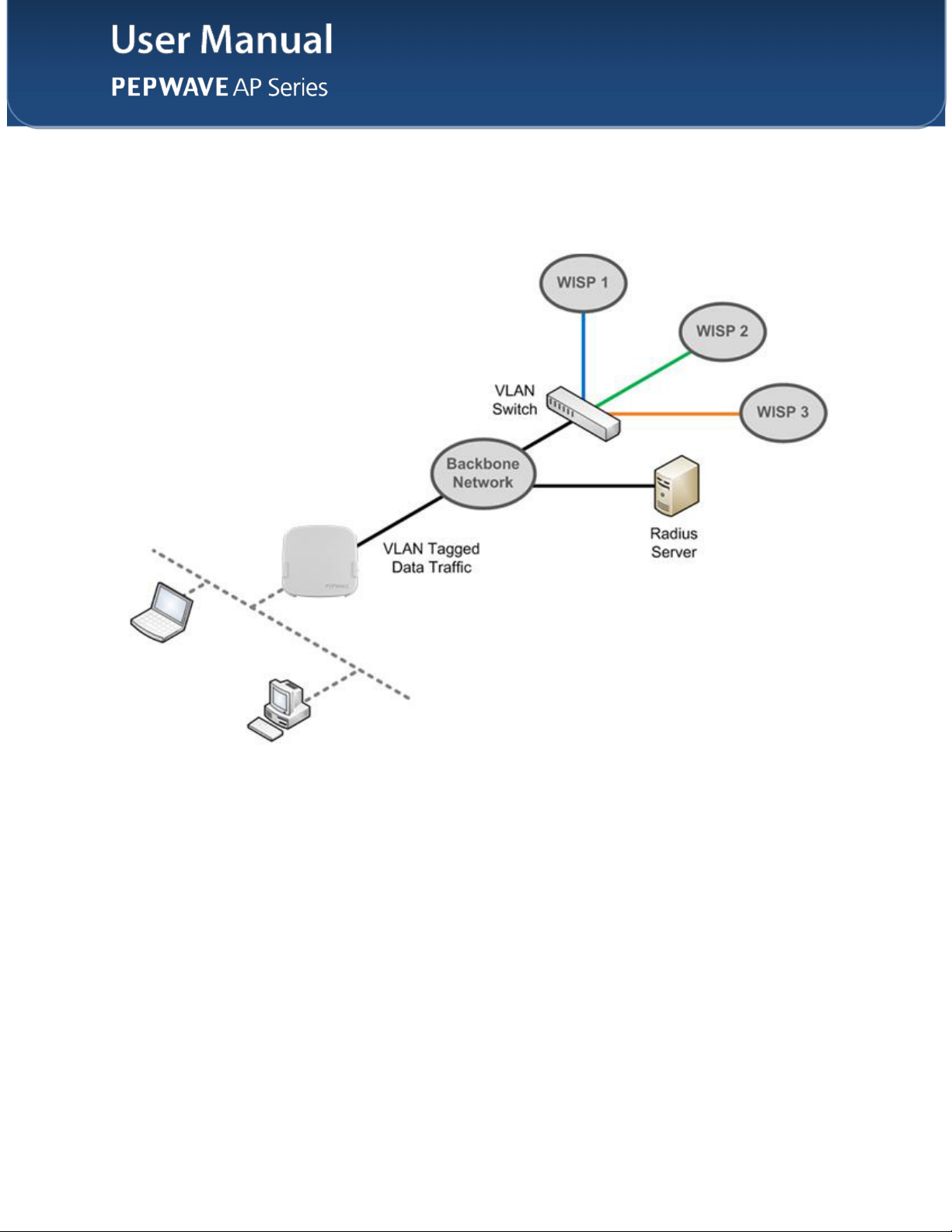
5 Installation
Your access point acts as a bridge between wireless and wired Ethernet interfaces. A
typical setup follows:
http://www.pepwave.com
13
Copyright ©
5/23/16
Pepwave
5.1 Installation Procedures
1. Connect the Ethernet port on the unit to the backbone network using an
Ethernet cable. The port should auto sense whether the cable is straightthrough or crossover.
2. Connect the power adapter to the power connector of the unit. Plug the power
adapter into a power source.
3. Wait for the status LED to turn green.
4. Connect a PC to the backbone network. Configure the IP address of the PC
to be any IP address between 192.168.0.4 and 192.168.0.254, with a subnet
mask of 255.255.255.0.
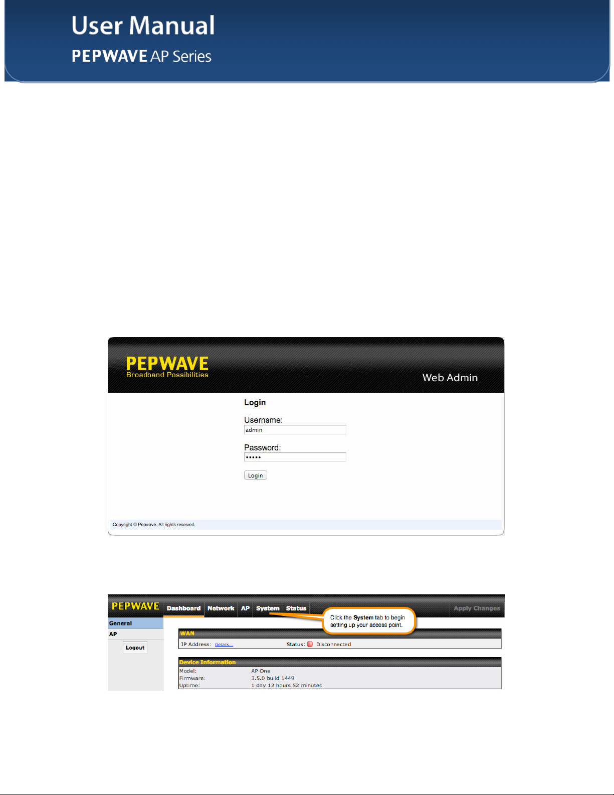
5. Using Microsoft Internet Explorer 6 or above, Mozilla Firefox 2.0 or above, or
Google Chrome 2.0 or above, connect to https://192.168.0.3.
6.
Enter the default admin login ID and password, admin and public
respectively.
7.
After logging in, the Dashboard appears. Click the System tab to begin
setting up your access point.
http://www.pepwave.com
14
Copyright ©
5/23/16
Pepwave

The Dashboard section contains a number of displays to keep you up-to-date on your
access point’s status and operation. Remote assistance can also be enabled here.
6.1 General
This section contains WAN status and general device information.
IP Address
Status
WAN
When your access point is connected to a WAN, this field displays the WAN IP
address. For more information, click the Details… link, which displays the following:
This field displays the current WAN connection status.
http://www.pepwave.com
15
Copyright ©
5/23/16
Pepwave

Device Information
Model
Firmware
Uptime
This field displays your access point’s model number.
The firmware version currently running on your access point appears here.
This field displays your access point’s uptime since the last reboot or shutdown.
http://www.pepwave.com
16
Copyright ©
5/23/16
Pepwave

6.2 AP
This section displays a variety of information about your wireless network.
Wireless Network
SSID
Radio
Security Policy
Channel
VLAN
http://www.pepwave.com
AP Status
This field displays your access point’s SSID.
The radio frequency currently used by your access point appears here. If you’re using
the AP One AC mini or the AP One In-Wall and have configured both radios, this
displays both radios in use.
This field displays the security policy your access point is currently using. If you’re using
the AP One AC mini and have configured both radios, this displays channels in use for
the 2.4GHz and 5GHz bands.
The channel currently used by your access point is displayed in this field.
If your access point is using a VLAN ID for management traffic, it will appear here. A
value of 0 indicates that a VLAN ID is not being used.
17
Copyright ©
5/23/16
Pepwave

7 Configuration
http://www.pepwave.com
18
Copyright ©
5/23/16
Pepwave

The options on the System tab control login and security settings, firmware upgrades,
SNMP settings, and other settings.
7.1.1 Admin Security
The Admin Security section allows you to set up your access point’s name, password,
security settings, and other options.
AP Name
Location
Admin User
Name
Admin Password
http://www.pepwave.com
Admin Security
Enter a name to identify your access point. This name can be retrieved via SNMP.
Enter a name to identify the location of your access point. This name can be retrieved
via SNMP.
This field specifies the administrator username of the web admin. It is set as admin by
default.
This field allows you to specify a new administrator password. The default password is
public.
19
Copyright ©
5/23/16
Pepwave

7.1.2 Firmware
http://www.pepwave.com
20
Copyright ©
5/23/16
Pepwave

access point, as well as check for and install new firmware via online download. You
can also upgrade your firmware using a firmware file stored locally.
To check for new firmware, click the Check for Firmware button. If new firmware is
available, your access point will automatically download and install it.
To upgrade your access point using a firmware file on your network, click Choose File
to select the firmware file. Then click Manual Upgrade to initiate the firmware upgrade
process using the selected file.
Note that your access point can store two different firmware versions in two different
partitions. A firmware upgrade will always replace the inactive partition. If you want to
keep the inactive firmware, simply reboot your device with the inactive firmware and
then perform the firmware upgrade.
7.1.3 Time
The settings in this section govern the access point’s system time zone and allow you to
specify a custom timeserver.
Time
Time Zone
Time Server
Time region used by the system. All choices are based on UTC.
To choose a time server other than the default, enter the URL here. To restore the
default time server, click the Default button.
7.1.4 Event Log
http://www.pepwave.com
21
Copyright ©
5/23/16
Pepwave

Event Log
Remote Syslog
Remote Syslog
Host
Check this box to turn on remote system logging.
Enter the IP address or hostname of the remote syslog server, as well as the port
number.
7.1.5 SNMP
SNMP, or simple network management protocol, is an open standard that can be used
22
http://www.pepwave.com
Copyright ©
5/23/16
Pepwave

settings to control simple network management protocol access.
SNMP Settings
SNMP Device
Name
SNMP Port
SNMPv1
SNMPv2c
SNMPv3
This field shows the AP name defined at System>Admin Security.
This option specifies the port which SNMP will use. The default port is 161.
This option allows you to enable SNMP version 1.
This option allows you to enable SNMP version 2c.
This option allows you to enable SNMP version 3.
To add a community for either SNMPv1 or SNMPv2c, click the Add SNMP Community
23
http://www.pepwave.com
Copyright ©
5/23/16
Pepwave

SNMP Community Settings
Community Name
IP Address/IP
Mask
Access Mode
Status
Enter a name for the SNMP community.
These settings specify a subnet from which access to the SNMP server is allowed.
Enter the subnet address here (e.g., 192.168.1.0) and select the appropriate subnet
mask.
Select Read Only or Read and Write as the SNMP community access mode.
Use these controls to enable or disable SNMP community access.
To define a user name for SNMPv3, click Add SNMP User in the SNMPv3 User Name
table, which displays the following screen:
SNMPv3 User Settings
SNMPv3 User
Name
Authentication
Protocol
Authentication
Password
Confirm
Authentication
Password
Privacy Protocol
Access Mode
Enter a user name to be used in SNMPv3.
Select one of the following valid authentication protocols:
• NONE
• HMAC-MD5
• HMAC-SHA
When HMAC-MD5 or HMAC-SHA is selected, an entry field will appear for the
password.
Enter a password to use with the selected authentication protocol.
Re-enter the authentication password.
Select None or CBC-DES as the SNMPv3 privacy protocol. When CBC-DES is
selected, an entry field will appear for the password.
Select Read Only or Read and Write as the SNMPv3 access mode.
http://www.pepwave.com
24
Copyright ©
5/23/16
Pepwave

7.1.6 Controller
In the Controller section, you can set up Peplink InControl or AP Controller remote
management.
Controller Management Settings
Controller
Management
Controller Type
Check this box to enable remote management.
Select Auto, InControl, or AP Controller as your remote AP management method.
When Auto is selected, your access point will automatically choose the appropriate
mode.
7.1.7 Configuration
In section, you can manage and backup access point configurations, as well as reset
your access point to its factory configuration. Backing up your access point’s settings
immediately after successful initial setup is strongly recommended.
http://www.pepwave.com
25
Copyright ©
5/23/16
Pepwave

Configuration
Restore
Configuration to
Factory Settings
Download Active
Configurations
Upload
Configurations
The Restore Factory Settings button resets the configuration to factory default
settings. After clicking the button, click the Apply Changes button on the top right
corner to make the settings effective. To save existing network settings when restoring
factory settings, check the Network Settings box before clicking Restore Factory
Settings.
Click Download to backup the current active settings.
To restore or change settings based on a configuration file, click Choose File to locate
the configuration file on the local computer, and then click Upload. The new settings
can then be applied by clicking the Apply Changes button on the page header, or you
can cancel the procedure by pressing discard on the main page of the web admin
interface.
7.1.8 Reboot
This section provides a reboot button for restarting the system. For maximum reliability,
your access point can equip with two copies of firmware, and each copy can be a
different version. You can select the firmware version you would like to reboot the
device with. The firmware marked with (Running) is the current system boot up
firmware.
Please note that a firmware upgrade will always replace the inactive firmware
partition.
26
http://www.pepwave.com
Copyright ©
5/23/16
Pepwave

7.2 AP
Use the controls on the AP tab to set the wireless SSID and AP settings, as well as
wireless distribution system (WDS) settings.
7.2.1 Wireless SSID
Wireless network settings, including the name of the network (SSID) and security policy,
can be defined and managed in this section.
http://www.pepwave.com
27
Copyright ©
5/23/16
Pepwave

modify its settings.
SSID Settings
Enable
Radio Selection
SSID
Broadcast SSID
Data Rate
Multicast Filter
Multicast Rate
IGMP Snooping
DHCP Setting
Check this box to enable wireless SSID.
Available only on the AP One AC mini, this setting, shown below, allows you to
enable or disable either of the two on-board radios.
This setting specifies the AP SSID that W i-Fi clients will see when scanning.
This setting specifies whether or not Wi-Fi clients can scan the SSID of this wireless
network. Broadcast SSID is enabled by default.
Select Auto to allow your access point to set the data rate automatically, or select
Fixed and choose a rate from the drop-down menu. Click the MCS Index link to
display a reference table containing MCS and matching HT20 and HT40 values.
This setting enables the filtering of multicast network traffic to the wireless SSID.
This setting specifies the transmit rate to be used for sending multicast network
traffic.
To allow your access point to convert multicast traffic to unicast traffic for associated
clients, select this option.
To set your access point as a DHCP server or relay, select Server or Relay.
Otherwise, select None.
DHCP Option 82
http://www.pepwave.com
If you use a distributed DHCP server/relay environment, you can enable this option to
provide additional information on the manner in which clients are physically
connected to the network.
28
Copyright ©
5/23/16
Pepwave

Security Policy
Security Settings
This setting configures the wireless authentication and encryption methods. Available
options are Open (No Encryption), WEP, 802.1X, WPA2 – Personal, WPA2 –
Enterprise, WPA/WPA2 - Personal, and WPA/WPA2 – Enterprise. To allow any
Wi-Fi client to access your AP without authentication, select Open (No Encryption).
Details on each of the available authentication methods follow.
http://www.pepwave.com
29
Copyright ©
5/23/16
Pepwave

WEP
Key Size
Key Format
Passphrase
Encryption Key
Shared Key
Authentication
Select 40 bits (64-bit WEP) or 104 bits (128-bit WEP).
Choose ASCII or Hex format for the WEP key. ASCII can be applied only to encryption
keys that are manually entered. Hex can be applied to encryption keys that are
manually entered or automatically generated.
Enter a series of alphanumeric characters, and then click Generate Key to create a
WEP key using the passphrase.
The generated WEP key appears here. Click Hide / Show Passphrase to toggle
visibility.
Check to enable shared key authentication. The default is disabled, meaning open
authentication is used.
802.1X
802.1X Version
WEP Key Size
Re-keying Period
http://www.pepwave.com
Choose v1 or v2 of the 802.1x EAPOL. When v1 is selected, both v1 and v2 clients can
associate with the access point. W hen v2 is selected, only v2 clients can associate with
the access point. Most modern wireless clients support v2. For stations that do not
support v2, select v1. The default is v2.
Select 40 bits (64-bit WEP) or 104 bits (128-bit WEP).
This option specifies the length of time throughout which the broadcast key remains
valid. When the re-keying period expires, the broadcast key is no longer valid and
broadcast key renewal is required. The default is 14400 seconds (four hours). 0
disables re-keying.
30
Copyright ©
5/23/16
Pepwave
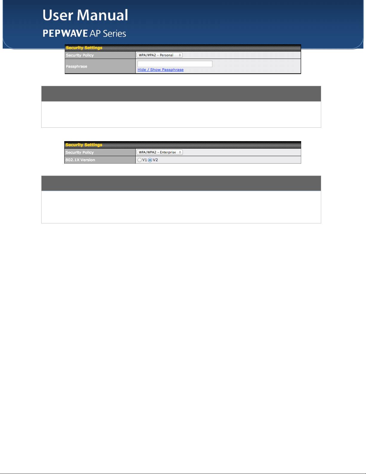
WPA/WPA2 – Personal
Passphrase
802.1X Version
Enter a passphrase of between 8 and 63 alphanumeric characters to create a
passphrase used for data encryption and authentication. Click Hide / Show
Passphrase to toggle visibility.
WPA/WPA2 – Enterprise
Choose v1 or v2 of the 802.1x EAPOL. When v1 is selected, both v1 and v2 clients can
associate with the access point. W hen v2 is selected, only v2 clients can associate with
the access point. Most modern wireless clients support v2. For stations that do not
support v2, select v1. The default is v2.
http://www.pepwave.com
31
Copyright ©
5/23/16
Pepwave

Web Portal Login
Web Portal
Authentication
Method
RADIUS Security
Splash Page
Landing Page
Landing Page
URL
Concurrent Login
Access Quota
Inactive Timeout
Select Enable to turn on your access point’s built-in web portal functionality.
Choose Open Access to allow users to connect without authentication or RADIUS to
require authentication. If RADIUS is selected, you’ll be given the opportunity to select a
RADIUS security method in the next field.
Select PAP, EAP-TTLS PAP, EAP-TTLS MSCHAPv2, or PEAPv0 EAP-MSCHAPv2.
If your web portal will use a splash page, choose HTTP or HTTPS and enter the splash
page’s URL.
If your web portal will use a landing page, check this box.
If you have checked Landing Page, enter your landing page’s URL here.
Check this box to allow users to have more than one logged in session active at a time.
Enter a value in minutes to limit access time on a given login or enter 0 to allow
unlimited use time on a single login. Likewise, enter a value in MB for the total
bandwidth allowed or enter 0 to allow unlimited bandwidth on a single login.
Enter a value in minutes to logout following the specified period of inactivity or enter 0 to
disable inactivity logouts.
Quota Reset Time
http://www.pepwave.com
This menu determines how your usage quota resets. Setting it to Daily will reset it at a
specified time every day. Setting a number of minutes after quota reached establishes
a timer for each user that begins after the quota has been reached.
32
Copyright ©
5/23/16
Pepwave

Access Control
Restricted Mode
MAC Address List
The settings allow administrator to control access using Mac address filtering. Available
options are None, Deny all except listed, Accept all except listed, and RADIUS MAC
Authentication.
Connections coming from the MAC addresses in this list will be either denied or
accepted based on the option selected in the previous field.
http://www.pepwave.com
33
Copyright ©
5/23/16
Pepwave

RADIUS Server Settings
Host
Secret
Authentication
Port
Accounting Port
Maximum
Retransmission
RADIUS Request
Interval
Enter the IP address of the primary RADIUS server and, if applicable, the secondary
RADIUS server.
Enter the RADIUS shared secret for the primary server and, if applicable, the secondary
RADIUS server.
Enter the UDP authentication port(s) used by your RADIUS server(s) or click the
Default button to enter 1812.
Enter the UDP accounting port(s) used by your RADIUS server(s) or click the Default
button to enter 1813.
Enter the maximum number of allowed retransmissions.
Enter a value in seconds to limit RADIUS request frequency. Note the initial value will
double on each retransmission.
http://www.pepwave.com
34
Copyright ©
5/23/16
Pepwave

Guest Protect
Block LAN
Access
Custom Subnet
Block Exception
Block PepVPN
Check this box to block access from the LAN.
To specify a subnet to block, enter the IP address and choose a subnet mask from the
drop-down menu. To add the blocked subnet, click . To delete a blocked subnet,
click .
To create an exception to a blocked subnet (above), enter the IP address and choose a
subnet mask from the drop-down menu. To add the exception, click . To delete
an exception, click .
To block PepVPN access, check this box.
Bandwidth
Management
Upstream Limit
Downstream Limit
Client Upstream
Limit
Client
http://www.pepwave.com
Bandwidth Management
Check this box to enable bandwidth management.
Enter a value in kpbs to limit the wireless network’s upstream bandwidth. Enter 0 to
allow unlimited upstream bandwidth.
Enter a value in kpbs to limit the wireless network’s downstream bandwidth. Enter 0 to
allow unlimited downstream bandwidth.
Enter a value in kpbs to limit connected clients’ upstream bandwidth. Enter 0 to allow
unlimited upstream bandwidth.
Enter a value in kpbs to limit connected clients’ downstream bandwidth. Enter 0 to allow
35
Copyright ©
5/23/16
Pepwave
 Loading...