


Pepwave MAX and Surf User Manual
Application
C
ompatibility
Normal
Application
Compatibility
Custom
highest application compatibility.
Outbound traffic from a source LAN device to the same destination Internet IP address will
be routed through the same WAN connection persistently, regardless of protocol. This
option provides high compatibility to most applications, and users still benefit from WAN link
load balancing when multiple Internet servers are accessed.
Outbound traffic behavior can be managed by defining rules in a custom rule table. A
default rule can be defined for connections that cannot be matched with any of the rules.
The default policy is Normal Application Compatibility.
Tip
Want to know more about creating outbound rules? Visit our YouTube Channel for a video tutorial!
http://youtu.be/rKH4AS_bQnE
15.2 Custom Rules for Outbound Policy
Click in the Outbound Policy form. Choose Custom and press the Save button.
http://www.pepwave.com 101 Copyright @ 2016 Pepwave

Pepwave MAX and Surf User Manual
The bottom-most rule is D
efault. Edit this rule to change the device’s default manner of
controlling outbound traffic for all connections that do not match any of the rules above
it. Under the Service heading, click Default to change these settings.
To rearrange the priority of outbound rules, drag and drop them into the desired
sequence.
By default, Auto is selected as the Default Rule. You can select Custom to change the
algorithm to be used. Please refer to the upcoming sections for the details on the
available algorithms.
To create a custom rule, click Add Rule at the bottom of the table. Note that some
Pepwave routers display this button at Advanced>PepVPN>PepVPN Outbound
Custom Rules.
http://www.pepwave.com 102 Copyright @ 2016 Pepwave

Pepwave MAX and Surf User Manual
Service Name
Enable
Source
Destination
New Custom Rule Settings
This setting specifies the name of the outbound traffic rule.
This setting specifies whether the outbound traffic rule takes effect. When Enable is
checked, the rule takes effect: traffic is matched and actions are taken by the Pepwave
router based on the other parameters of the rule. When Enable is unchecked, the rule does
not take effect: the Pepwave router disregards the other parameters of the rule.
Click the drop-down menu next to the checkbox to apply a time schedule to this custom
rule.
This setting specifies the source IP address, IP network, or MAC address for traffic that
matches the rule.
This setting specifies the destination IP address, IP network, or domain name for traffic that
matches the rule.
If Domain Name is chosen and a domain name, such as foobar.com, is entered, any
outgoing accesses to foobar.com and *.foobar.com will match this criterion. You may enter
a wildcard (.*) at the end of a domain name to match any host with a name having the
domain name in the middle. If you enter foobar.*, for example, www.foobar.com,
www.foobar.co.jp, or foobar.co.uk will also match. Placing wildcards in any other position is
not supported.
NOTE: if a server has one Internet IP address and multiple server names, and if one of the
names is defined here, accesses to any one of the server names will also match this rule.
http://www.pepwave.com 103 Copyright @ 2016 Pepwave

Pepwave MAX and Surf User Manual
Protocol and Port
Algorithm
Terminate
Sessions on Link
Recovery
This setting specifies the IP protocol and port of traffic that matches this rule.
This setting specifies the behavior of the Pepwave router for the custom rule.
One of the following values can be selected (note that some Pepwave routers provide only
some of these options):
Weighted Balance
Persistence
Enforced
Priority
Overflow
Least Used
Lowest Latency
The upcoming sections detail the listed algorithms.
This setting specifies whether to terminate existing IP sessions on a less preferred WAN
connection in the event that a more preferred WAN connection is recovered. This setting is
applicable to the Weighted, Persistence, and Priority algorithms. By default, this setting is
disabled. In this case, existing IP sessions will not be terminated or affected when any other
WAN connection is recovered. When this setting is enabled, existing IP sessions may be
terminated when another WAN connection is recovered, such that only the preferred
healthy WAN connection(s) is used at any point in time.
http://www.pepwave.com 104 Copyright @ 2016 Pepwave

Pepwave MAX and Surf User Manual
15.2.1 Algorithm: Weighted Balance
T
his setting specifies the ratio of WAN connection usage to be applied on the specified
IP protocol and port. This setting is applicable only when Algorithm is set to Weighted
Balance.
The amount of matching traffic that is distributed to a WAN connection is proportional to
the weight of the WAN connection relative to the total weight. Use the sliders to change
each WAN’s weight.
For example, with the following weight settings:
• Ethernet WAN1: 10
• Ethernet WAN2: 10
• Wi-Fi WAN: 10
• Cellular 1: 10
• Cellular 2: 10
• USB: 10
otal weight is 60 = (10 +10 + 10 + 10 + 10 + 10).
T
Matching traffic distributed to Ethernet WAN1 is 16.7% = (10 / 60 x 100%.
Matching traffic distributed to Ethernet WAN2 is 16.7% = (10 / 60) x 100%.
Matching traffic distributed to Wi-Fi WAN is 16.7% = (10 / 60) x 100%.
Matching traffic distributed to Cellular 1 is 16.7% = (10 / 60) x 100%.
Matching traffic distributed to Cellular 2 is 16.7% = (10 / 60) x 100%.
Matching traffic distributed to USB is 16.7% = (10 / 60) x 100%.
http://www.pepwave.com 105 Copyright @ 2016 Pepwave

Pepwave MAX and Surf User Manual
15.2.2 Algorithm: Persistence
T
he configuration of persistent services is the solution to the few situations where link
load distribution for Internet services is undesirable. For example, for security reasons,
many e-banking and other secure websites terminate the session when the client
computer’s Internet IP address changes mid-session.
In general, different Internet IP addresses represent different computers. The security
concern is that an IP address change during a session may be the result of an
unauthorized intrusion attempt. Therefore, to prevent damages from the potential
intrusion, the session is terminated upon the detection of an IP address change.
Pepwave routers can be configured to distribute data traffic across multiple WAN
connections. Also, the Internet IP depends on the WAN connections over which
communication actually takes place. As a result, a LAN client computer behind the
Pepwave router may communicate using multiple Internet IP addresses. For example, a
LAN client computer behind a Pepwave router with three WAN connections may
communicate on the Internet using three different IP addresses.
With the persistence feature, rules can be configured to enable client computers to
persistently utilize the same WAN connections for e-banking and other secure websites.
As a result, a client computer will communicate using one IP address, eliminating the
issues mentioned above.
There are two persistent modes: By Source and By Destination.
By Source: The same WAN connection will be used for traffic matching the rule and originating from
the same machine, regardless of its destination. This option will provide the highest level
of application compatibility.
By Destination: The same WAN connection will be used for traffic matching the rule, originating from the
same machine, and going to the same destination. This option can better distribute loads
to WAN connections when there are only a few client machines.
The default mode is By Source. When there are multiple client requests, they can be
distributed (persistently) to WAN connections with a weight. If you choose Auto in Load
Distribution, the weights will be automatically adjusted according to each WAN’s
Downstream Bandwidth which is specified in the WAN settings page). If you choose
Custom, you can customize the weight of each WAN manually by using the sliders.
http://www.pepwave.com 106 Copyright @ 2016 Pepwave

Pepwave MAX and Surf User Manual
15.2.3 Algorithm: Enforced
T
his setting specifies the WAN connection usage to be applied on the specified IP
protocol and port. This setting is applicable only when Algorithm is set to Enforced.
Matching traffic will be routed through the specified WAN connection, regardless of the
health check status of the WAN connection. Starting from Firmware 5.2, outbound traffic
can be enforced to go through a specified SpeedFusion
15.2.4 Algorithm: Priority
TM
connection.
This setting specifies the priority of the WAN connections used to route the specified
network service. The highest priority WAN connection available will always be used for
routing the specified type of traffic. A lower priority WAN connection will be used only
when all higher priority connections have become unavailable.
Starting from Firmware 5.2, outbound traffic can be prioritized to go through
TM
SpeedFusion
connection(s). By default, VPN connections are not included in the
priority list.
Tip
Configure multiple distribution rules to accommodate different kinds of services.
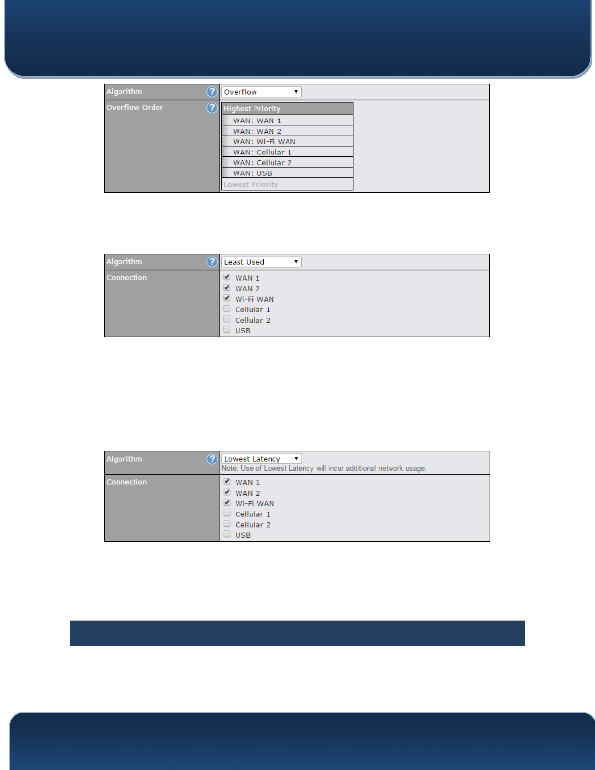
15.2.5 Algorithm: Overflow
The traffic matching this rule will be routed through the healthy WAN connection that
has the highest priority and is not in full load. When this connection gets saturated, new
sessions will be routed to the next healthy WAN connection that is not in full load.
http://www.pepwave.com 107 Copyright @ 2016 Pepwave
Pepwave MAX and Surf User Manual
D
rag and drop to specify the order of WAN connections to be used for routing traffic.
Only the highest priority healthy connection that is not in full load will be used.
15.2.6 Algorithm: Least Used
The traffic matching this rule will be routed through the healthy WAN connection that is
selected in Connection and has the most available download bandwidth. The available
download bandwidth of a WAN connection is calculated from the total download
bandwidth specified on the WAN settings page and the current download usage. The
available bandwidth and WAN selection is determined every time an IP session is
made.
15.2.7 Algorithm: Lowest Latency
he traffic matching this rule will be routed through the healthy WAN connection that is
T
selected in Connection and has the lowest latency. Latency checking packets are
issued periodically to a nearby router of each WAN connection to determine its latency
value. The latency of a WAN is the packet round trip time of the WAN connection.
Additional network usage may be incurred as a result.
Tip
The roundtrip time of a 6M down/640k uplink can be higher than that of a 2M down/2M up link because the overall
round trip time is lengthened by its slower upload bandwidth, despite its higher downlink speed. Therefore, this
algorithm is good for two scenarios:
• All WAN connections are symmetric; or
http://www.pepwave.com 108 Copyright @ 2016 Pepwave

Pepwave MAX and Surf User Manual
• A latency sensitive application must be routed through the lowest latency WAN, regardless of the WAN’s
available bandwidth.
15.2.8 Expert Mode
Expert Mode is available on some Pepwave routers for use
by advanced users. To enable the feature, click on the help
icon and click turn on Expert Mode.
TM
In Expert Mode, a new special rule, SpeedFusion
Routes, is displayed in the Custom Rules table. This rule
represents all SpeedFusionTM routes learned from remote
VPN peers. By default, this bar is on the top of all custom
rules. This position means that traffic for remote VPN
subnets will be routed to the corresponding VPN peer. You
can create custom Priority or Enforced rules and move them
above the bar to override the SpeedFusion
TM
routes.
Upon disabling Expert Mode, all rules above the bar will be removed.
http://www.pepwave.com 109 Copyright @ 2016 Pepwave
Pepwave MAX and Surf User Manual
16 Inbound Access
16.1 Port Forwarding Service
Pepwave routers can act as a firewall that blocks, by default, all inbound access from
the Internet. By using port forwarding, Internet users can access servers behind the
Pepwave router. Inbound port forwarding rules can be defined at Advanced>Port
Forwarding.
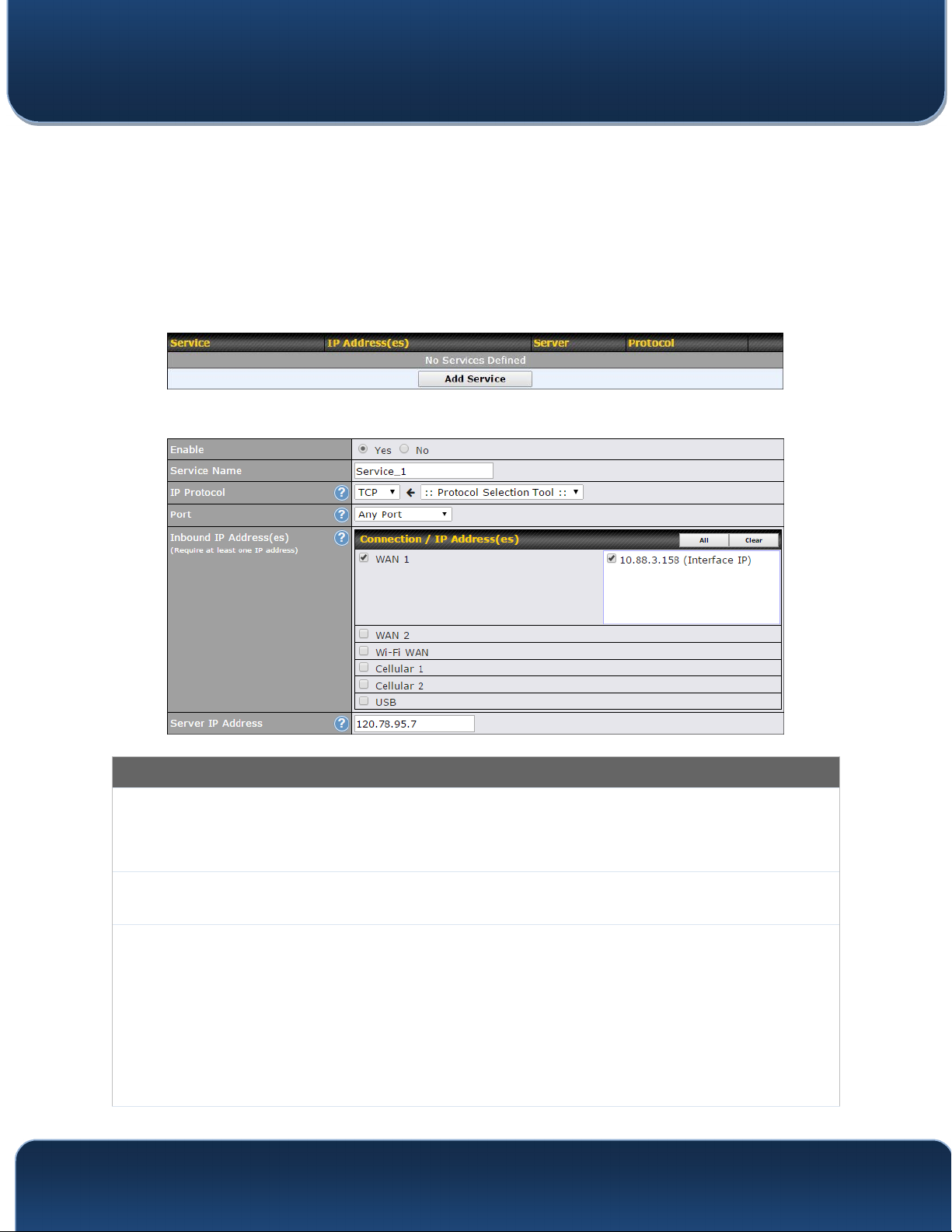
To define a new service, click Add Service.
Port Forwarding Settings
This setting specifies whether the inbound service takes effect. When Enable is checked, the
Enable
Service
Name
IP Protocol
inbound service takes effect: traffic is matched and actions are taken by the Pepwave router
based on the other parameters of the rule. When this setting is disabled, the inbound service
does not take effect: the Pepwave router disregards the other parameters of the rule.
This setting identifies the service to the system administrator. Valid values for this setting
consist of only alphanumeric and underscore “_” characters.
The IP Protocol setting, along with the Port setting, specifies the protocol of the service as
TCP, UDP, ICMP, or IP. Traffic that is received by the Pepwave router via the specified protocol
at the specified port(s) is forwarded to the LAN hosts specified by the Servers setting. Please
see below for details on the Port and Servers settings. Alternatively, the Protocol Selection
Tool drop-down menu can be used to automatically fill in the protocol and a single port number
of common Internet services (e.g. HTTP, HTTPS, etc.). After selecting an item from the
Protocol Selection Tool drop-down menu, the protocol and port number remain manually
modifiable.
http://www.pepwave.com 110 Copyright @ 2016 Pepwave

Pepwave MAX and Surf User Manual
The Port setting specifies the port(s) that correspond to the service, and can be configured to
behave in one of the following manners:
Any Port, Single Port, Port Range, Port Map, and Range Mapping
Any Port: all traffic that is received by the Pepwave router via the specified protocol is
forwarded to the servers specified by the Servers setting. For example, with IP Protocol set to
TCP, and Port set to Any Port, all TCP traffic is forwarded to the configured servers.
Single Port: traffic that is received by the Pepwave router via the specified protocol at the
specified port is forwarded via the same port to the servers specified by the Servers setting.
For example, with IP Protocol set to TCP, and Port set to Single Port and Service Port 80,
TCP traffic received on port 80 is forwarded to the configured servers via port 80.
Port Range: traffic that is received by the Pepwave router via the specified protocol at the
Port
specified port range is forwarded via the same respective ports to the LAN hosts specified by
the Servers setting. For example, with IP Protocol set to TCP, and Port set to Port Range and
Service Ports 80-88, TCP traffic received on ports 80 through 88 is forwarded to the configured
servers via the respective ports.
Port Mapping: traffic that is received by Pepwave router via the specified protocol at the
specified port is forwarded via a different port to the servers specified by the Servers setting.
For example, with IP Protocol set to TCP, and Port set to Port Mapping, Service Port 80, and
Map to Port 88, TCP traffic on port 80 is forwarded to the configured servers via port 88.
(Please see below for details on the Servers setting.)
Range Mapping: traffic that is received by the Pepwave router via the specified protocol at the
specified port range is forwarded via a different port to the servers specified by the Servers
setting.
Inbound IP
Address(es)
Server IP
Address
This setting specifies the WAN connections and Internet IP address(es) from which the service
can be accessed.
This setting specifies the LAN IP address of the server that handles the requests for the
service.
http://www.pepwave.com 111 Copyright @ 2016 Pepwave
Pepwave MAX and Surf User Manual
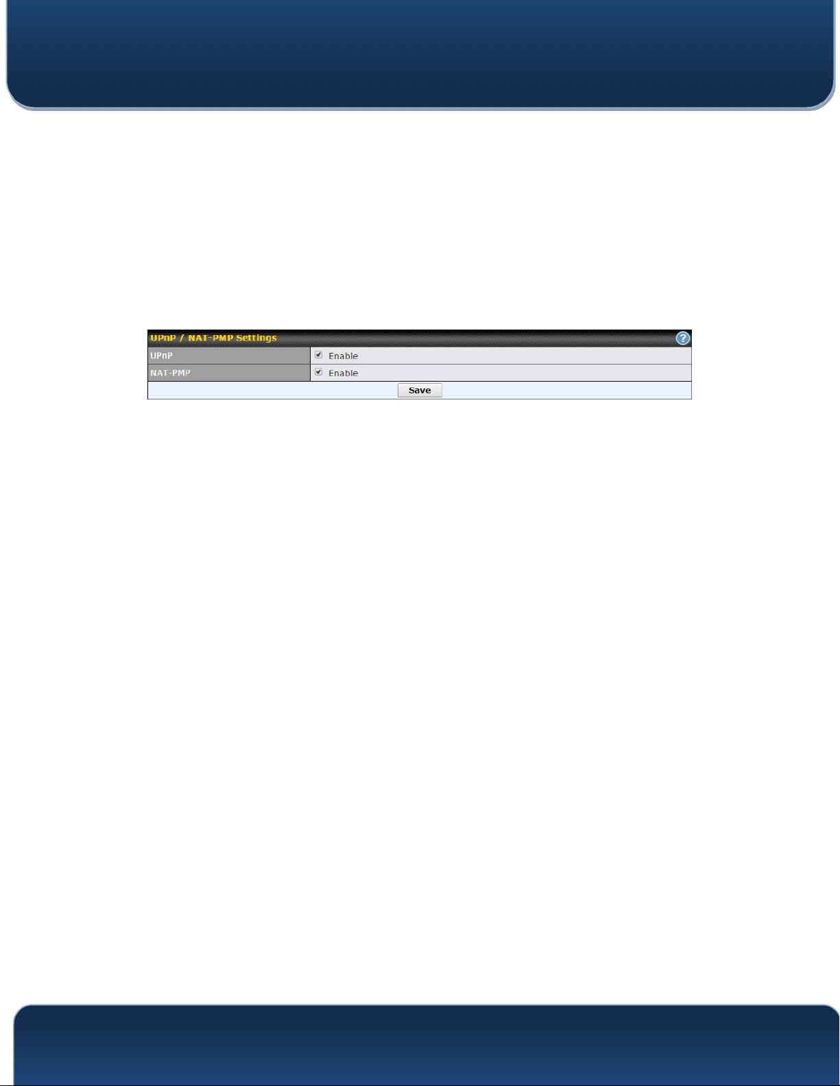
16.1.1 UPnP / NAT-PMP Settings
U
PnP and NAT-PMP are network protocols which allow a computer connected to the
LAN port to automatically configure the router to allow parties on the WAN port to
connect to itself. That way, the process of inbound port forwarding becomes
automated.
When a computer creates a rule using these protocols, the specified TCP/UDP port of
all WAN connections' default IP address will be forwarded.
Check the corresponding box(es) to enable UPnP and/or NAT-PMP. Enable these
features only if you trust the computers connected to the LAN ports.
When the options are enabled, a table listing all the forwarded ports under these two
protocols can be found at Status>UPnP / NAT-PMP.
http://www.pepwave.com 112 Copyright @ 2016 Pepwave
Pepwave MAX and Surf User Manual
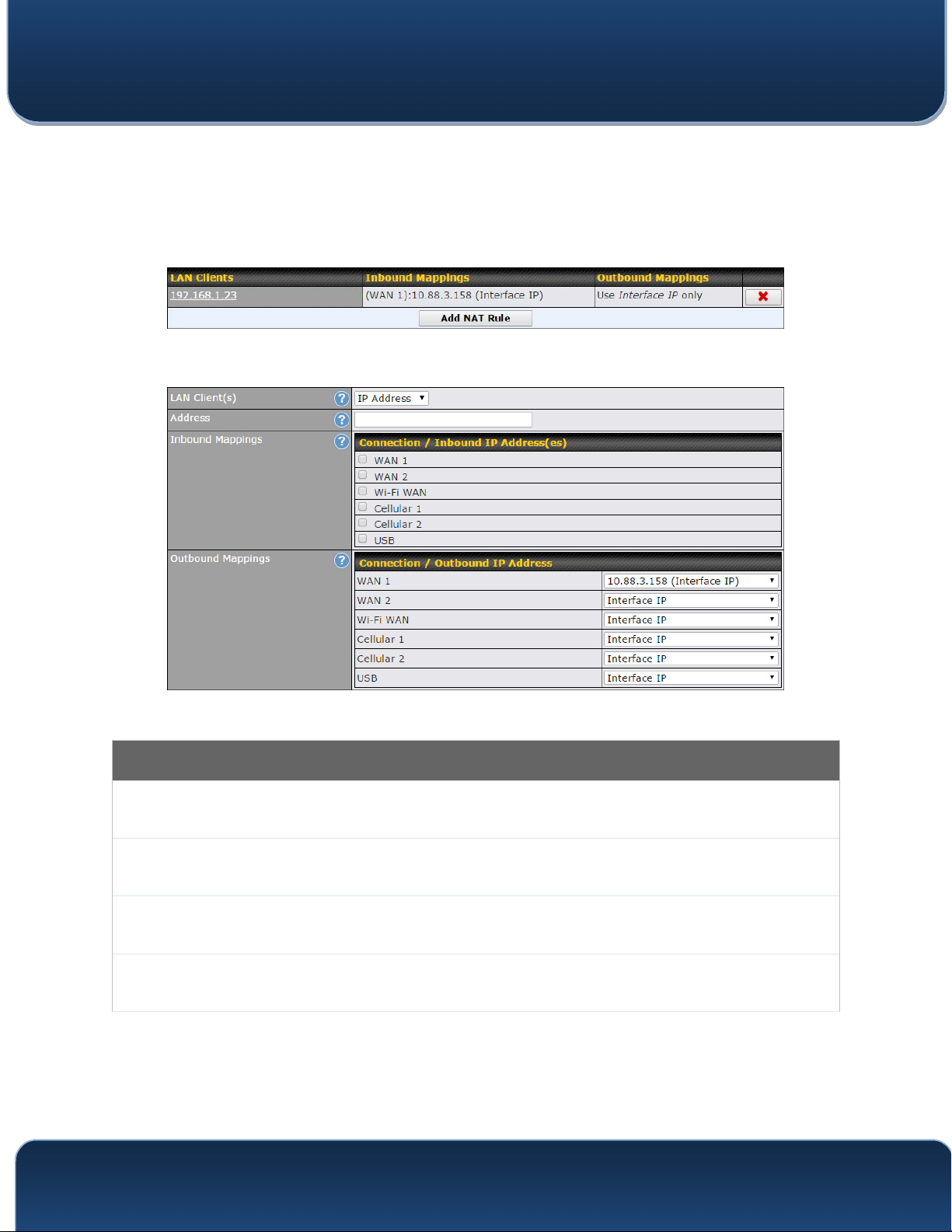
17 NAT Mappings
NAT mappings allow IP address mapping of all inbound and outbound NAT’dt raffic to
and from an internal client IP address. Settings to configure NAT mappings are located
at Advanced>NAT Mappings.
To add a rule for NAT mappings, click Add NAT Rule.
LAN
Client(s)
Address
Range
Network
NAT Mapping Settings
NAT mapping rules can be defined for a single LAN IP Address, an IP Range, or an IP
Network.
This refers to the LAN host’s private IP address. The system maps this address to a
number of public IP addresses (specified below) in order to facilitate inbound and
outbound traffic. This option is only available when IP Address is selected.
The IP range is a contiguous group of private IP addresses used by the LAN host. The
system maps these addresses to a number of public IP addresses (specified below) to
facilitate outbound traffic. This option is only available when IP Range is selected.
The IP network refers to all private IP addresses and ranges managed by the LAN host.
The system maps these addresses to a number of public IP addresses (specified below)
to facilitate outbound traffic. This option is only available when IP Network is selected.
http://www.pepwave.com 113 Copyright @ 2016 Pepwave

Pepwave MAX and Surf User Manual
This setting specifies the WAN connections and corresponding WAN-specific Internet IP
addresses on which the system should bind. Any access to the specified WAN
Inbound
M
appings
Outbound
Mappings
Click Save to save the settings when configuration has been completed.
connection(s) and IP address(es) will be forwarded to the LAN host. This option is only
available when IP Address is selected in the LAN Client(s) field.
Note that inbound mapping is not needed for WAN connections in drop-in mode or IP
forwarding mode. Also note that each WAN IP address can be associated to one NAT
mapping only.
This setting specifies the WAN IP addresses that should be used when an IP connection
is made from a LAN host to the Internet. Each LAN host in an IP range or IP network will
be evenly mapped to one of each selected WAN's IP addresses (for better IP address
utilization) in a persistent manner (for better application compatibility).
Note that if you do not want to use a specific WAN for outgoing accesses, you should still
choose default here, then customize the outbound access rule in the Outbound Policy
section. Also note that WAN connections in drop-in mode or IP forwarding mode are not
shown here.
Important Note
Inbound firewall rules override the Inbound Mappings settings.
http://www.pepwave.com 114 Copyright @ 2016 Pepwave

Pepwave MAX and Surf User Manual
18 QoS
18.1 User Groups
LAN and PPTP clients can be categorized into three user groups: Manager, Staff, and
Guest. This menu allows you to define rules and assign client IP addresses or subnets
to a user group. You can apply different bandwidth and traffic prioritization policies on
each user group in the Bandwidth Control and Application sections (note that the
options available here vary by model).
The table is automatically sorted by rule precedence. The smaller and more specific
subnets are put towards the top of the table and have higher precedence; larger and
less specific subnets are placed towards the bottom.
Click the Add button to define clients and their user group. Click the button to
remove the defined rule. Two default rules are pre-defined and put at the bottom. They
are All DHCP reservation clients and Everyone, and they cannot be removed. The
All DHCP reservation client represents the LAN clients defined in the DHCP
Reservation table on the LAN settings page. Everyone represents all clients that are
not defined in any rule above. Click on a rule to change its group.
Add / Edit User Group
From the drop-down menu, choose whether you are going to define the client(s) by
Subnet / IP
Address
Group
an IP Address or a Subnet. If IP Address is selected, enter a name defined in DHCP
reservation table or a LAN client's IP address. If Subnet is selected, enter a subnet
address and specify its subnet mask.
This field is to define which User Group the specified subnet / IP address belongs to.
Once users have been assigned to a user group, their internet traffic will be restricted by
rules defined for that particular group. Please refer to the following two sections for
details.
http://www.pepwave.com 115 Copyright @ 2016 Pepwave

Pepwave MAX and Surf User Manual
18.2 Bandwidth Control
You can define a maximum download speed (over all WAN connections) and upload
speed (for each WAN connection) that each individual Staff and Guest member can
consume. No limit can be imposed on individual Manager members. By default,
download and upload bandwidth limits are set to unlimited (set as 0).
18.3 Application
18.3.1 Application Prioritization
On many Pepwave routers, you can choose whether to apply the same prioritization
settings to all user groups or customize the settings for each group.
Three application priority levels can be set: ↑↑↑↑High,━━━━ Normal, and↓↓↓↓Low. Pepwave
routers can detect various application traffic types by inspecting the packet content.
Select an application by choosing a supported application, or by defining a custom
application manually. The priority preference of supported applications is placed at the
top of the table. Custom applications are at the bottom.
http://www.pepwave.com 116 Copyright @ 2016 Pepwave

Pepwave MAX and Surf User Manual
18.3.2 Prioritization for Custom Applications
C
lick the Add button to define a custom application. Click the button in the Action
column to delete the custom application in the corresponding row.
When Supported Applications is selected, the Pepwave router will inspect network
traffic and prioritize the selected applications. Alternatively, you can select Custom
Applications and define the application by providing the protocol, scope, port number,
and DSCP value.
18.3.3 DSL/Cable Optimization
SL/cable-based WAN connections have lower upload bandwidth and higher
D
download bandwidth. When a DSL/cable circuit's uplink is congested,
the download bandwidth will be affected. Users will not be able to download data at full
speed until the uplink becomes less congested. DSL/Cable Optimization can relieve
such an issue. When it is enabled, the download speed will become less affected by the
upload traffic. By default, this feature is enabled.
http://www.pepwave.com 117 Copyright @ 2016 Pepwave

Pepwave MAX and Surf User Manual
19 Firewall
A firewall is a mechanism that selectively filters data traffic between the WAN side (the
Internet) and the LAN side of the network. It can protect the local network from potential
hacker attacks, access to offensive websites, and/or other inappropriate uses.
The firewall functionality of Pepwave routers supports the selective filtering of data
traffic in both directions:
Outbound (LAN to WAN)
Inbound (WAN to LAN)
he firewall also supports the following functionality:
T
Intrusion detection and DoS prevention
Web blocking
With SpeedFusionTM enabled, the firewall rules also apply to VPN tunneled traffic.
19.1 Outbound and Inbound Firewall Rules
19.1.1 Access Rules
The outbound firewall settings are located at Advanced>Firewall>Access
Rules>Outbound Firewall Rules.
http://www.pepwave.com 118 Copyright @ 2016 Pepwave

Pepwave MAX and Surf User Manual
C
lick Add Rule to display the following screen:
Inbound firewall settings are located at Advanced>Firewall>Access Rules>Inbound
Firewall Rules.
Click Add Rule to display the following screen:
Rules are matched from top to bottom. If a connection matches any one of the upper
rules, the matching process will stop. If none of the rules match, the Default rule will be
applied. By default, the Default rule is set as Allow for both outbound and inbound
access.
http://www.pepwave.com 119 Copyright @ 2016 Pepwave
Pepwave MAX and Surf User Manual
Inbound / Outbound Firewall Settings
Rule Name
Enable
WAN
Connection
(Inbound)
Protocol
This setting specifies a name for the firewall rule.
This setting specifies whether the firewall rule should take effect. If the box is checked, the
firewall rule takes effect. If the traffic matches the specified protocol/IP/port, actions will be
taken by the Pepwave router based on the other parameters of the rule. If the box is not
checked, the firewall rule does not take effect. The Pepwave router will disregard the other
parameters of the rule.
Click the dropdown menu next to the checkbox to place this firewall rule on a time
schedule.
Select the WAN connection that this firewall rule should apply to.
This setting specifies the protocol to be matched. Via a drop-down menu, the following
protocols can be specified:
• TCP
• UDP
• ICMP
• IP
Alternatively, the Protocol Selection Tool drop-down menu can be used to automatically
fill in the protocol and port number of common Internet services (e.g., HTTP, HTTPS, etc.)
After selecting an item from the Protocol Selection Tool drop-down menu, the protocol
and port number remains manually modifiable.
Source IP &
Port
Destination IP
& Port
Action
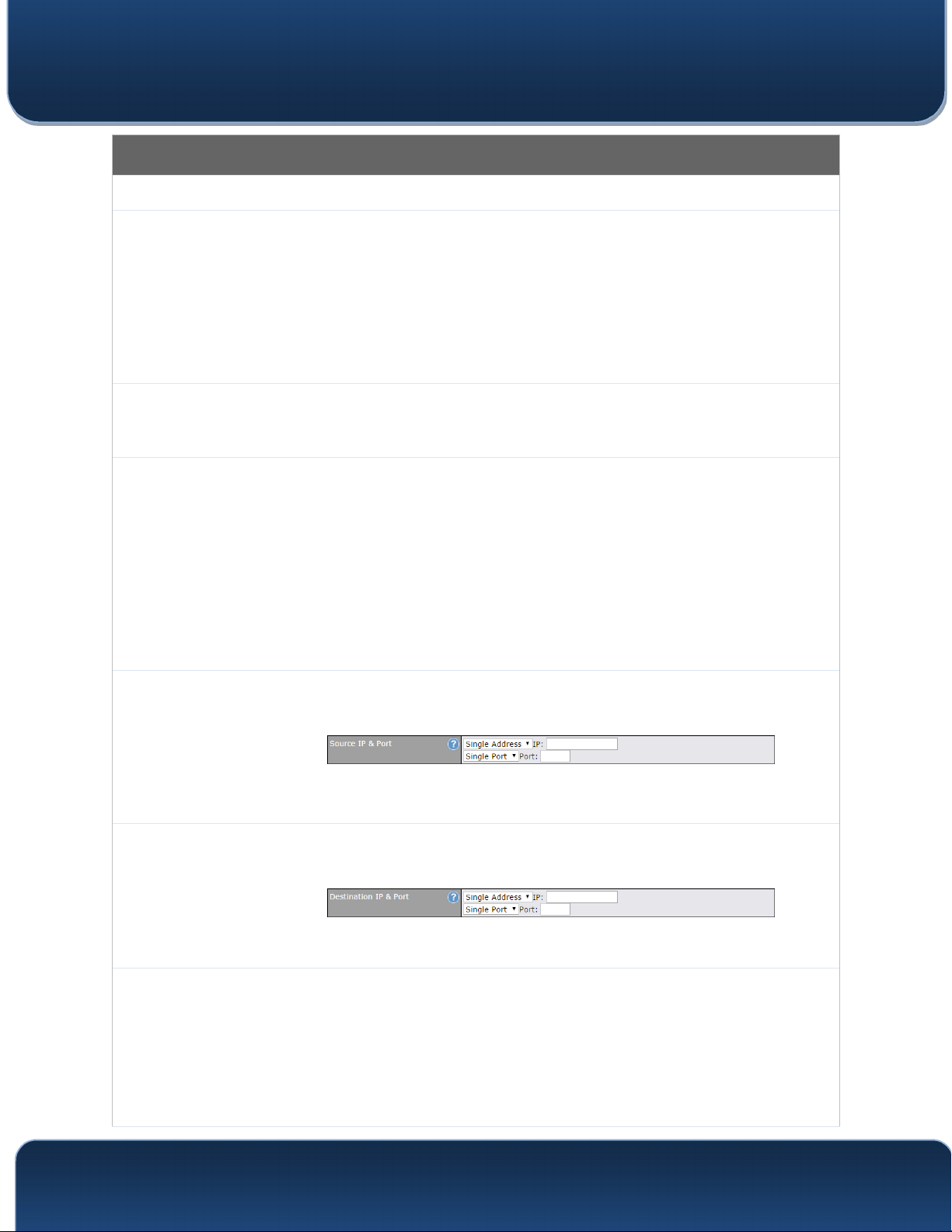
This specifies the source IP address(es) and port number(s) to be matched for the firewall
rule. A single address, or a network, can be specified as the Source IP & Port setting, as
indicated by the following screenshot:
In addition, a single port, or a range of ports, can be specified for the Source IP & Port
settings.
This specifies the destination IP address(es) and port number(s) to be matched for the
firewall rule. A single address, or a network, can be specified as the Destination IP & Port
setting, as indicated by the following screenshot:
In addition, a single port, or a range of ports, can be specified for the Destination IP & Port
settings.
This setting specifies the action to be taken by the router upon encountering traffic that
matches the both of the following:
• Source IP & port
• Destination IP & port
With the value of Allow for the Action setting, the matching traffic passes through the
router (to be routed to the destination). If the value of the Action setting is set to Deny, the
matching traffic does not pass through the router (and is discarded).
http://www.pepwave.com 120 Copyright @ 2016 Pepwave

Pepwave MAX and Surf User Manual
This setting specifies whether or not to log matched firewall events. The logged messages
are shown on the page Status>Event Log. A sample message is as follows:
Aug 13 23:47:44 Denied CONN=Ethernet WAN SRC=20.3.2.1
DST=192.168.1.20 LEN=48 PROTO=TCP SPT=2260 DPT=80
• CONN: The connection where the log entry refers to
Event Logging
Click Save to store your changes. To create an additional firewall rule, click Add Rule
and repeat the above steps.
To change a rule’s priority, simply drag and drop the rule:
• SRC: Source IP address
• DST: Destination IP address
• LEN: Packet length
• PROTO: Protocol
• SPT: Source port
• DPT: Destination port
• Hold the left mouse button on the rule.
• Move it to the desired position.
• Drop it by releasing the mouse button.
Tip
If the default inbound rule is set to Allow for NAT-enabled WANs, no inbound Allow firewall rules will be required
for inbound port forwarding and inbound NAT mapping rules. However, if the default inbound rule is set as Deny,
a corresponding Allow firewall rule will be required.
http://www.pepwave.com 121 Copyright @ 2016 Pepwave

Pepwave MAX and Surf User Manual
19.1.2 Apply Firewall Rules to PepVpn Traffic
W
hen this option is enabled, Outbound Firewall Rules will be applied to PepVPN traffic.
To turn on this feature, click , check the Enable check box, and press the Save
button.
19.1.3 Intrusion Detection and DoS Prevention
epwave routers can detect and prevent intrusions and denial-of-service (DoS) attacks
P
from the Internet. To turn on this feature, click , check the Enable check box, and
press the Save button.
When this feature is enabled, the Pepwave router will detect and prevent the following
kinds of intrusions and denial-of-service attacks.
• Port scan
o NMAP FIN/URG/PSH
o Xmas tree
o Another Xmas tree
o Null scan
o SYN/RST
o SYN/FIN
• SYN flood prevention
• Ping flood attack prevention
http://www.pepwave.com 122 Copyright @ 2016 Pepwave

Pepwave MAX and Surf User Manual
19.2 Content Blocking
19.2.1 Application Blocking
Choose applications to be blocked from LAN/PPTP/PepVPN peer clients' access,
except for those on the Exempted User Groups or Exempted Subnets defined below.
19.2.2 Web Blocking
Defines web site domain names to be blocked from LAN/PPTP/PepVPN peer clients'
access except for those on the Exempted User Groups or Exempted Subnets defined
below.
http://www.pepwave.com 123 Copyright @ 2016 Pepwave

Pepwave MAX and Surf User Manual
If "foobar.com" is entered, any web site with a host
name ending in foobar.com will be
blocked, e.g. www.foobar.com, foobar.com, etc. However, "myfoobar.com" will not be
blocked.
You may enter the wild card ".*" at the end of a domain name to block any web site with
a host name having the domain name in the middle. If you enter "foobar.*", then
"www.foobar.com", "www.foobar.co.jp", or "foobar.co.uk" will be blocked. Placing the
wild card in any other position is not supported.
The device will inspect and look for blocked domain names on all HTTP traffic. Secure
web (HTTPS) traffic is not supported.
19.2.3 Customized Domains
nter an appropriate website address, and the Peplink Balance will block and disallow
E
LAN/PPTP/SpeedFusionTM peer clients to access these websites. Exceptions can be
added using the instructions in Sections 20.1.3.2 and 20.1.3.3.
You may enter the wild card ".*" at the end of a domain name to block any web site with
a host name having the domain name in the middle. For example, If you enter
"foobar.*," then "www.foobar.com," "www.foobar.co.jp," or "foobar.co.uk" will be
blocked. Placing the wild card in any other position is not supported.
The Peplink Balance will inspect and look for blocked domain names on all HTTP traffic.
Secure web (HTTPS) traffic is not supported.
19.2.4 Exempted User Groups
Check and select pre-defined user group(s) who can be exempted from the access
blocking rules. User groups can be defined at QoS>User Groups section. Please refer
to Section 17.1 for details.
19.2.5 Exempted Subnets
ith the subnet defined in the field, clients on the particular subnet(s) can be exempted
W
from the access blocking rules.
19.2.6 URL Logging
Click enable, and the enter the ip address and port (if applicable) where your remote
syslog server is located.
19.3 OSPF & RIPv2
The Peplink Balance supports OSPF and RIPv2 dynamic routing protocols. Click the
Network tab from the top bar, and then click the OSPF & RIPv2 item on the sidebar to
reach the following menu:
http://www.pepwave.com 124 Copyright @ 2016 Pepwave

Pepwave MAX and Surf User Manual
OSPF
Router ID
Area
This field determines the ID of the router. By default, this is specified as the LAN IP
address. If you want to specify your own ID, enter it in the Custom field.
This is an overview of the OSPFv2 areas you have defined. Click on the area name to
configure it. To set a new area, click Add. To delete an existing area, click .
OSPF Settings
Area ID
Link Type
Authentication
Interfaces
Determine the name of your Area ID to apply to this group. Machines linked to this group
will send and receive related OSPF packets, while unlinked machines will ignore it.
Choose the network type that this area will use.
Choose an authentication method, if one is used, from this drop-down menu. Available
options are MD5 and Text. Enter the authentication key next to the drop-down menu.
Determine which interfaces this area will use to listen to and deliver OSPF packets
http://www.pepwave.com 125 Copyright @ 2016 Pepwave

Pepwave MAX and Surf User Manual
To access RIPv2 settings, click .
RIPv2 Settings
Authentication
Interfaces
Choose an authentication method, if one is used, from this drop-down menu. Available
options are MD5 and Text. Enter the authentication key next to the drop-down menu.
Determine which interfaces this group will use to listen to and deliver RIPv2 packets.
19.4 Remote User Access
a Networks routed by a Peplink Balance can be remotely accessed via L2TP with IPsec
or PPTP. To configure this feature, navigate to Network > Remote User Access
http://www.pepwave.com 126 Copyright @ 2016 Pepwave

Pepwave MAX and Surf User Manual
Enable
VPN Type
Preshared Key
Listen On
User Accounts
Remote User Access Settings
Click the checkbox to enable Remote User Access.
Determine whether remote devices can connect to the Balance using L2TP with IPsec or
PPTP. For greater security, we recommend you connect using L2TP with IPsec.
Enter your preshared key in the text field. Please note that remote devices will need this
preshared key to access the Balance.
This setting is for specifying the WAN IP addresses where the PPTP server of the router
should listen on.
This setting allows you to define the PPTP User Accounts. Click Add to input username and
password to create an account. After adding the user accounts, you can click on a
username to edit the account password. Click the button X to delete the account in its
corresponding row.
Click the button to switch to enters user accounts by pasting the information in.CSV
format.
http://www.pepwave.com 127 Copyright @ 2016 Pepwave
Pepwave MAX and Surf User Manual
Miscellaneous Settings
The miscellaneous settings include configuration for high availability, PPTP server,
service forwarding, and service passthrough.
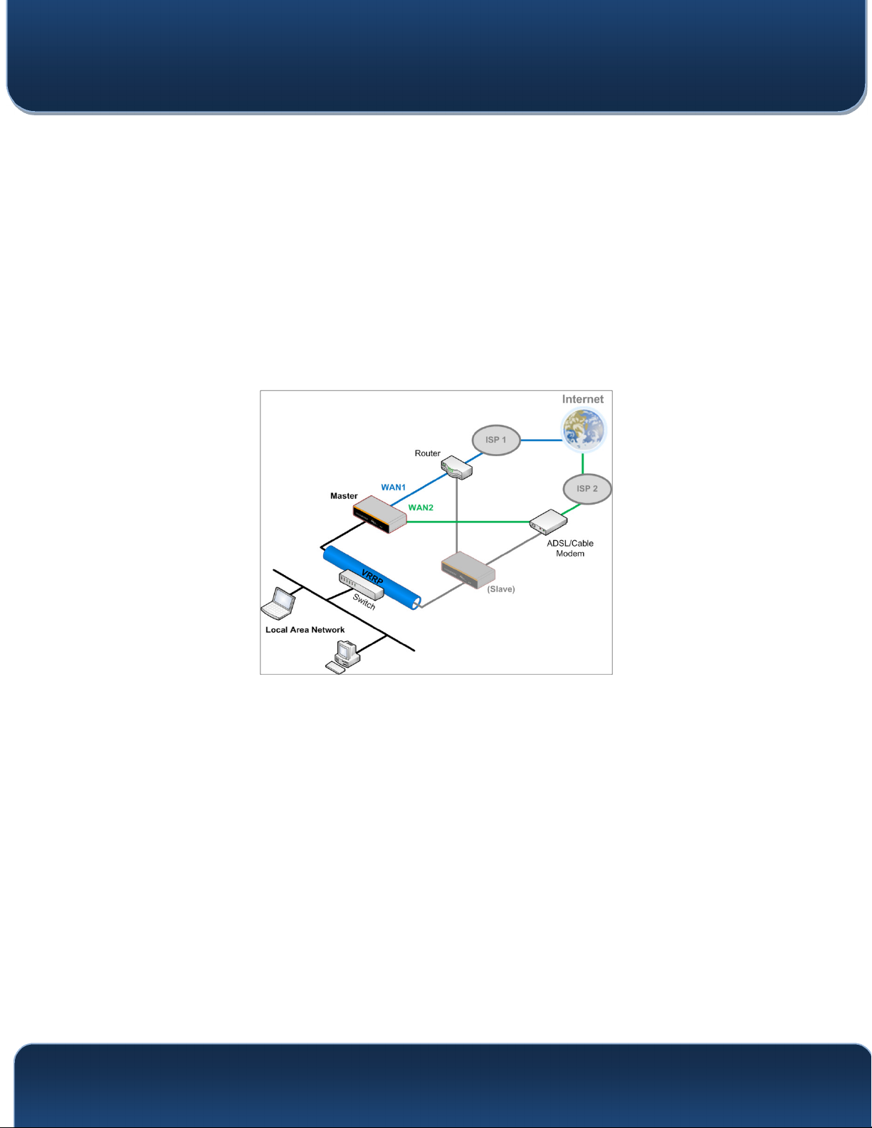
19.5 High Availability
Many Pepwave routers support high availability (HA) configurations via an open
standard virtual router redundancy protocol (VRRP, RFC 3768). In an HA configuration,
two Pepwave routers provide redundancy and failover in a master-slave arrangement.
In the event that the master unit is down, the slave unit becomes active. High availability
will be disabled automatically where there is a drop-in connection configured on a LAN
bypass port.
In the diagram, the WAN ports of each Pepwave router connect to the router and to the
modem. Both Pepwave routers connect to the same LAN switch via a LAN port.
An elaboration on the technical details of the implementation of the virtual router
redundancy protocol (VRRP, RFC 3768) by Pepwave routers follows:
In an HA configuration, the two Pepwave routers comm
using VRRP over the LAN.
The two Pepwave routers broadcast heartbeat signals to the LAN at a frequency
of one heartbeat signal per second.
In the event that no heartbeat signal from the master Pepwave router is received
in 3 seconds (or longer) since the last heartbeat signal, the slave Pepwave router
becomes active.
The slave Pepwave router initiates the WAN connectio
previously configured LAN IP address.
At a subsequent point when the master Pepwave router recovers, it will once
again become active.
http://www.pepwave.com 128 Copyright @ 2016 Pepwave
unicate with each other
ns and binds to a

Administration
Pepwave MAX and Surf User Manual
Y
ou can configure high availability at Advanced>Misc. Settings>High Availability.
Interface for Master Router Interface for Slave Router
Enable
Group Number
Preferred Role
Resume
Master Role
Upon
Recovery
Configuration
Sync.
Master Serial
Number
Virtual IP
High Availability
Checking this box specifies that the Pepwave router is part of a high availability configuration.
This number identifies a pair of Pepwave routers operating in a high availability configuration.
The two Pepwave routers in the pair must have the same Group Number value.
This setting specifies whether the Pepwave router operates in master or slave mode. Click
the corresponding radio button to set the role of the unit. One of the units in the pair must be
configured as the master, and the other unit must be configured as the slave.
This option is displayed when Master mode is selected in Preferred Role. If this option is
enabled, once the device has recovered from an outage, it will take over and resume its
Master role from the slave unit.
This option is displayed when Slave mode is selected in Preferred Role. If this option is
enabled and the Master Serial Number entered matches with the actual master unit's, the
master unit will automatically transfer the configuration to this unit. Please make sure
the LAN IP Address and the Subnet Mask fields are set correctly in the LAN settings page.
You can refer to the Event Log for the configuration synchronization status.
If Configuration Sync. is checked, the serial number of the master unit is required here for
the feature to work properly.
The HA pair must share the same Virtual IP. The Virtual IP and the LAN Administration IP
must be under the same network.
http://www.pepwave.com 129 Copyright @ 2016 Pepwave
LAN
IP
Subnet Mask
This setting specifies a LAN IP address to be used for accessing administration functionality.
This address should be unique within the LAN.
This setting specifies the subnet mask of the LAN.

Pepwave MAX and Surf User Manual
Important Note
For Pepwave routers in NAT mode, the virtual IP (VIP) should be set as the default gateway for all hosts on the
LAN segment. For example, a firewall sitting behind the Pepwave router should set its default gateway as the
virtual IP instead of the IP of the master router.
In drop-in mode, no other configuration needs to be set.
Please note that the drop-in WAN cannot be configured as a LAN bypass port while it is configured for high
availability.
http://www.pepwave.com 130 Copyright @ 2016 Pepwave

Pepwave MAX and Surf User Manual
19.6 PPTP Server
Pepwave routers feature a built-in PPTP server, which enables remote computers to
conveniently and securely access the local network. PPTP server settings are located at
Advanced>Misc. Settings>PPTP Server.
Check the box to enable PPTP server functionality. All connected PPTP sessions are
displayed at Status>Client List. Please refer to Section 22.3 for details. Note that
available options vary by model.
http://www.pepwave.com 131 Copyright @ 2016 Pepwave
Pepwave MAX and Surf User Manual
PPTP Server Settings
Listen On
Authentication
User Accounts
This setting is for specifying the WAN connection(s) and IP address(es) that the PPTP
server should listen on.
This setting is for specifying the user database source for PPTP authentication. Three
sources can be selected: Local User Accounts, LDAP Server, or RADIUS Server.
Local User Accounts - User accounts are stored in the Pepwave router locally. You can
add/modify/delete accounts in the User Accounts table.
LDAP Server - Authenticate with an external LDAP server. This has been tested with Open
LDAP servers where passwords are NTLM hashed. Active Directory is not supported. (You
can choose to use RADIUS to authenticate with a Windows server.)
RADIUS Server - Authenticate with an external RADIUS server. This has been tested with
Microsoft Windows Internet Authentication Service and FreeRADIUS servers where
passwords are NTLM hashed or in plain text.
This setting allows you to define PPTP user accounts for authentication via local user
accounts. Click Add to input username and password to create an account. After adding
the user accounts, you can click on a username to edit the account password. Click
to delete the account in its corresponding row.
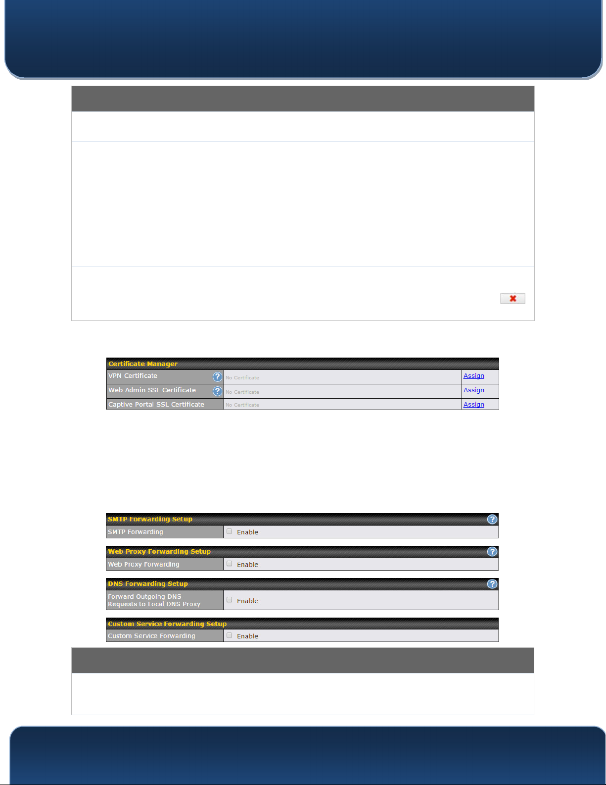
19.7 Certificate Manager
This section allows you to assign certificates for l
ocal VPN and web admin SSL. The
local keys will not be transferred to another device by any means.
19.8 Service Forwarding
Service forwarding settings are located at Advanced>Misc. Settings>Service
Forwarding.
Service Forwarding
When this option is enabled, all outgoing SMTP connections destined for any host at
SMTP Forwarding
TCP port 25 will be intercepted. These connections will be redirected to a specified
SMTP server and port number. SMTP server settings for each WAN can be specified
http://www.pepwave.com 132 Copyright @ 2016 Pepwave

Pepwave MAX and Surf User Manual
after selecting Enable.
When this option is enabled, all outgoing connections destined for the proxy server
Web Proxy
Forwarding
DNS Forwarding
specified in Web Proxy Interception Settings will be intercepted. These
connections will be redirected to a specified web proxy server and port number. Web
proxy interception settings and proxy server settings for each WAN can be specified
after selecting Enable.
When this option is enabled, all outgoing DNS lookups will be intercepted and
redirected to the built-in DNS name server. If any LAN device is using the DNS name
servers of a WAN connection, you may want to enable this option to enhance the
DNS availability without modifying the DNS server setting of the clients. The built-in
DNS name server will distribute DNS lookups to corresponding DNS servers of all
available WAN connections. In this case, DNS service will not be interrupted, even if
any WAN connection is down.
Custom Service
Forwarding
When custom service forwarding is enabled, outgoing traffic with the specified TCP
port will be forwarded to a local or remote server by defining its IP address and port
number.
19.8.1 SMTP Forwarding
Some ISPs require their users to send e-mails via the ISP’s SMTP server. All outgoing
SMTP connections are blocked except those connecting to the ISP’s. Pepwave routers
support intercepting and redirecting all outgoing SMTP connections (destined for TCP
port 25) via a WAN connection to the WAN’s corresponding SMTP server.
To enable the feature, select Enable under SMTP Forwarding Setup. Check Enable
Forwarding for the WAN connection(s) that needs forwarding. Under SMTP Server,
enter the ISP’s e-mail server host name or IP address. Under SMTP Port, enter the
TCP port number for each WAN.
The Pepwave router will intercept SMTP connections. Choose a WAN port according to
the outbound policy, and then forward the connection to the SMTP server if the chosen
WAN has enabled forwarding. If the forwarding is disabled for a WAN connection,
SMTP connections for the WAN will be simply be forwarded to the connection’s original
destination.
Note
If you want to route all SMTP connections only to particular WAN connection(s), you should create a custom rule
http://www.pepwave.com 133 Copyright @ 2016 Pepwave
Pepwave MAX and Surf User Manual
in outbound policy (see Section 14.2).
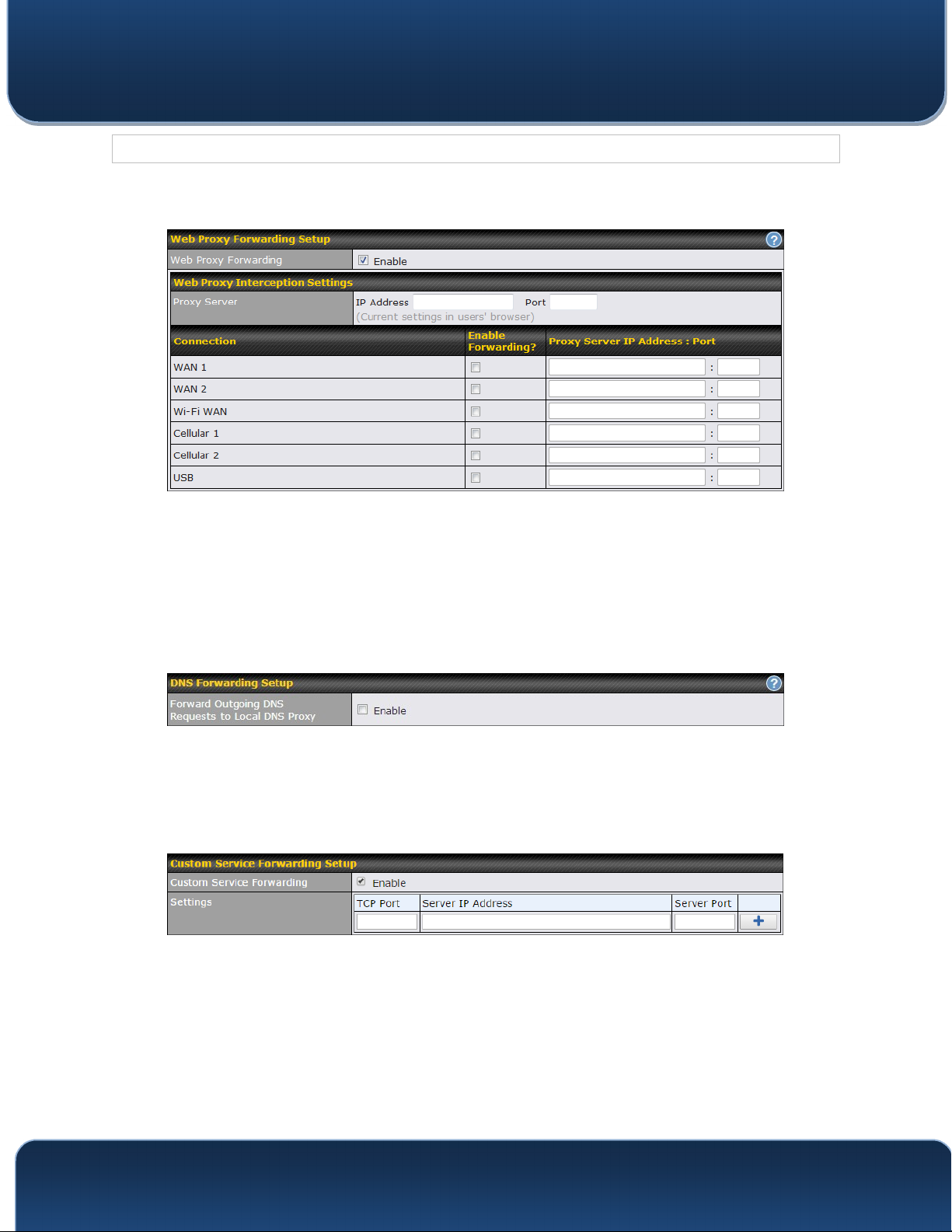
19.8.2 Web Proxy Forwarding
When this feature is enabled, the Pepwave router will intercept all outgoing connections
destined for the proxy server specified in Web Proxy Interception Settings, choose a
WAN connection with reference to the outbound policy, and then forward them to the
specified web proxy server and port number. Redirected server settings for each WAN
can be set here. If forwarding is disabled for a WAN, web proxy connections for the
WAN will be simply forwarded to the connection’s original destination.
19.8.3 DNS Forwarding
hen DNS forwarding is enabled, all clients’ outgoing DNS requests will also be
W
intercepted and forwarded to the built-in DNS proxy server.
19.8.4 Custom Service Forwarding
After clicking the enable checkbox, enter your TCP port for traffic heading to the router,
and then specify the IP Address and Port of the server you wish to forward to the service
to.
http://www.pepwave.com 134 Copyright @ 2016 Pepwave
Pepwave MAX and Surf User Manual
19.9 Service Passthrough
Service passthrough settings can be found at Advanced>Misc. Settings>Service
Passthrough.
Some Internet services need to be specially handled in a multi-WAN environment.
Pepwave routers can handle these services such that Internet applications do not notice
being behind a multi-WAN router. Settings for service passthrough support are available
here.
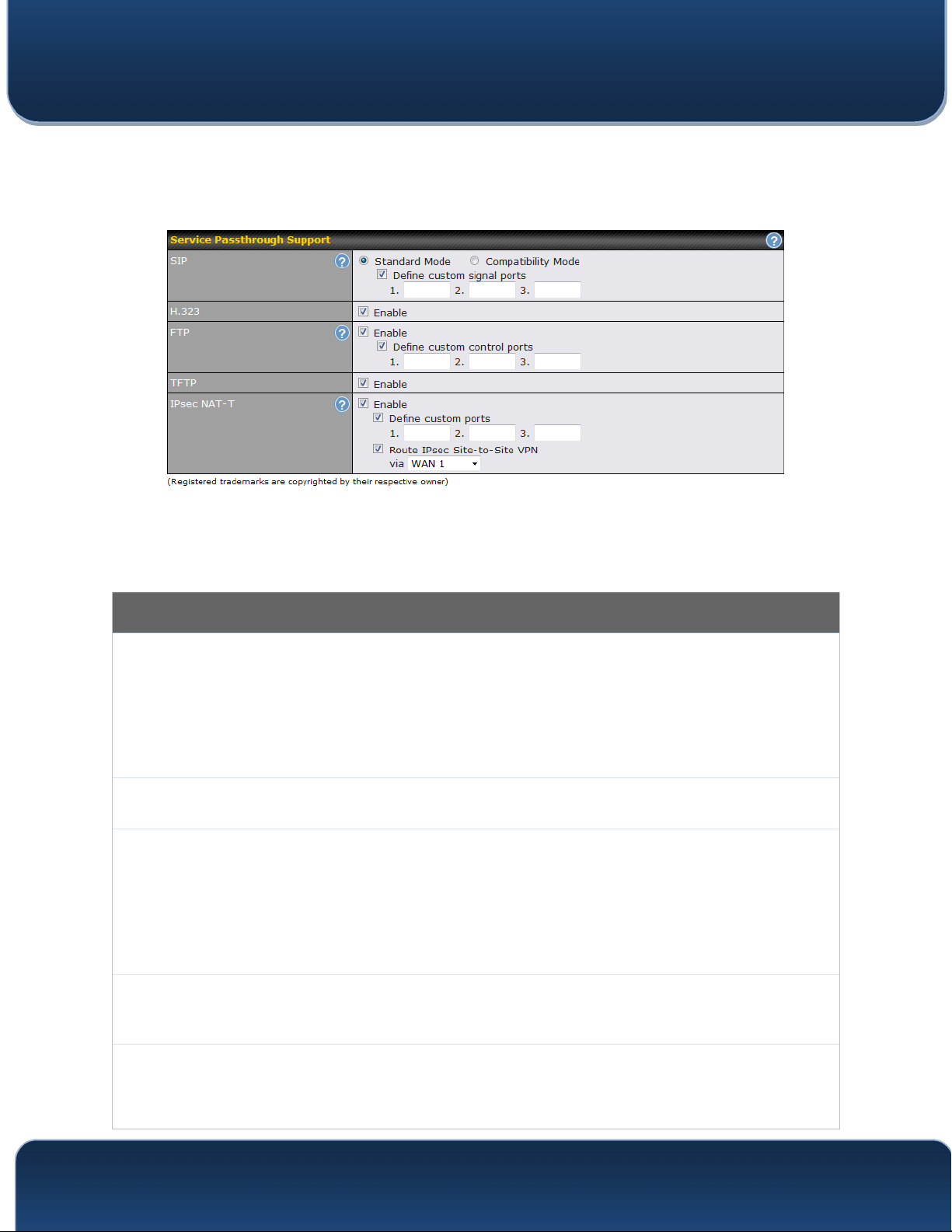
Service Passthrough Support
Session initiation protocol, aka SIP, is a voice-over-IP protocol. The Pepwave router can
act as a SIP application layer gateway (ALG) which binds connections for the same SIP
session to the same WAN connection and translate IP address in the SIP packets
SIP
H.323
FTP
correctly in NAT mode. Such passthrough support is always enabled, and there are two
modes for selection: Standard Mode and Compatibility Mode. If your SIP server’s
signal port number is non-standard, you can check the box Define custom signal ports
and input the port numbers to the text boxes.
With this option enabled, protocols that provide audio-visual communication sessions will
be defined on any packet network and pass through the Pepwave router.
FTP sessions consist of two TCP connections; one for control and one for data. In a
multi-WAN situation, they must be routed to the same WAN connection. Otherwise,
problems will arise in transferring files. By default, the Pepwave router monitors TCP
control connections on port 21 for any FTP connections and binds TCP connections of
the same FTP session to the same WAN. If you have an FTP server listening on a port
number other than 21, you can check Define custom control ports and enter the port
numbers in the text boxes.
The Pepwave router monitors outgoing TFTP connections and routes any incoming
TFTP
IPsec NAT-T
TFTP data packets back to the client. Select Enable if you want to enable TFTP
passthrough support.
This field is for enabling the support of IPsec NAT-T passthrough. UDP ports 500, 4500,
and 10000 are monitored by default. You may add more custom data ports that your
IPsec system uses by checking Define custom ports. If the VPN contains IPsec site-tosite VPN traffic, check Route IPsec Site-to-Site VPN and choose the WAN connection
http://www.pepwave.com 135 Copyright @ 2016 Pepwave

Pepwave MAX and Surf User Manual
to route the traffic to.
19.10 GPS Forwarding
Using the GPS forwarding feature, some Pepwave routers can automatically send GPS
reports to a specified server. To set up GPS forwarding, navigate to Advanced>GPS
Forwarding.
Enable
Server
GPS Report
Format
NMEA Sentence
Type
Vehicle ID
TAIP Sentence
Type/TAIP ID
(optional)
GPS Forwarding
Check this box to turn on GPS forwarding.
Enter the name/IP address of the server that will receive GPS data. Also specify a port
number, protocol (UDP or TCP), and a report interval of between 1 and 10 seconds.
Click to save these settings.
Choose from NMEA or TAIP format for sending GPS reports.
If you’ve chosen to send GPS reports in NMEA format, select one or more sentence
types for sending the data (GPRMC, GPGGA, GPVTG, GPGSA, and GPGSV).
The vehicle ID will be appended in the last field of the NMEA sentence. Note that the
NMEA sentence will become customized and non-standard.
If you’ve chosen to send GPS reports in TAIP format, select one or more sentence types
for sending the data (PV—Position / Velocity Solution and CP—Compact Velocity
Solution). You can also optionally include an ID number in the TAIP ID field.
http://www.pepwave.com 136 Copyright @ 2016 Pepwave
Pepwave MAX and Surf User Manual
20 AP Controller
The AP controller acts as a centralized controller of Pepwave AP devices. With this
feature, users can customize and manage multiple APs from a single Pepwave router
interface.
Special Note
Each Pepwave router can control a limited number of routers without additional cost. To manage more, a Full
Edition license is required. Please contact your Authorized Reseller or the Peplink Sales Team for more
information and pricing details.
To configure, navigate to the AP tab.
20.1 Wireless SSID
This menu is the first one that appears after clicking the AP tab. This screen can also be
reached by clicking AP>Wireless SSID. Note the appearance of this screen varies by
model.
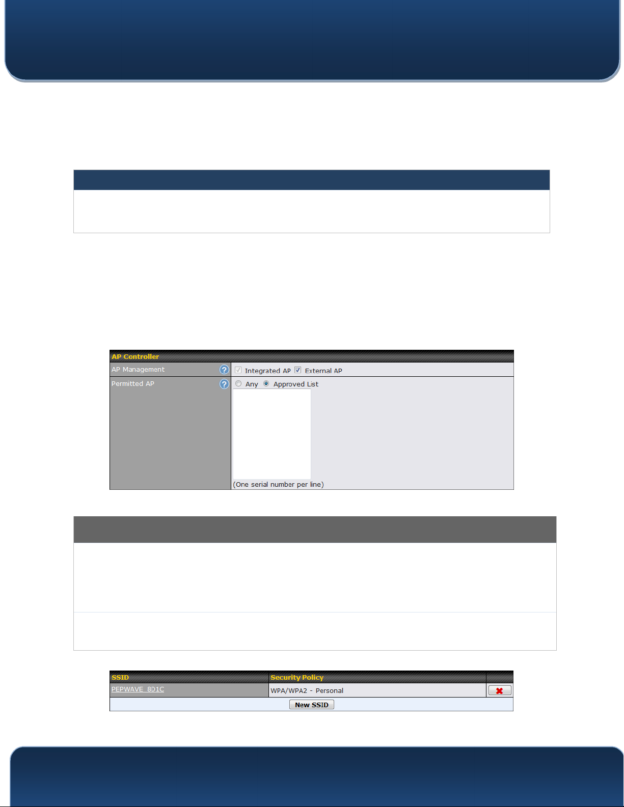
AP Controller
The AP controller for managing Pepwave APs can be enabled by checking this box. When
AP
Management
Permitted AP
this option is enabled, the AP controller will wait for management connections originating from
APs over the LAN on TCP and UDP port 11753. It will also wait for captive portal connections
on TCP port 443. An extended DHCP option, CAPWAP Access Controller addresses (field
138), will be added to the DHCP server. A local DNS record, AP Controller, will be added to
the local DNS proxy.
Access points to manage can be specified here. If Any is selected, the AP controller will
manage any AP that reports to it. If Approved List is selected, only APs with serial numbers
listed in the provided text box will be managed.
http://www.pepwave.com 137 Copyright @ 2016 Pepwave

Pepwave MAX and Surf User Manual
C
urrent SSID information appears in the SSID section. To edit an existing SSID, click its
name in the list. To add a new SSID, click Add. Note that the following settings vary by
model.
SSID
Enable
VLAN ID
Broadcast SSID
Data Rate A
Multicast FilterA
SSID Settings
This setting specifies the SSID of the virtual AP to be scanned by Wi-Fi clients.
Select Yes to enable the virtual AP.
This setting specifies the VLAN ID to be tagged on all outgoing packets generated
from this wireless network (i.e., packets that travel from the Wi-Fi segment through
the Pepwave AP One unit to the Ethernet segment via the LAN port). The default
value of this setting is 0, which means VLAN tagging is disabled (instead of tagged
with zero).
This setting specifies whether or not Wi-Fi clients can scan the SSID of this wireless
network. Broadcast SSID is enabled by default.
Select Auto to allow the Pepwave router to set the data rate automatically, or select
Fixed and choose a rate from the displayed drop-down menu.
This setting enables the filtering of multicast network traffic to the wireless SSID.
http://www.pepwave.com 138 Copyright @ 2016 Pepwave

Pepwave MAX and Surf User Manual
This setting specifies the transmit rate to be used for sending multicast network
A
Multicast Rate
IGMP Snooping A
DHCP Option 82 A
traffic. The selected Protocol and Channel Bonding settings will affect the rate
options and values available here.
To allow the Pepwave router to listen to internet group management protocol (IGMP)
network traffic, select this option.
If you use a distributed DHCP server/relay environment, you can enable this option to
provide additional information on the manner in which clients are physically
connected to the network.
Network Priority
(QoS) A
Layer 2 Isolation A
Band Steering A
A
- Advanced feature. Click the button on the top right-hand corner to activate.
Select from Gold, Silver, and Bronze to control the QoS priority of this wireless
network’s traffic.
Layer 2 refers to the second layer in the ISO Open System Interconnect model.
When this option is enabled, clients on the same VLAN, SSID, or subnet are isolated
to that VLAN, SSID, or subnet, which can enhance security. Traffic is passed to
upper communication layer(s). By default, the setting is disabled.
Band steering allows the Pepwave router to steer AP clients from the 2.4GHz band to
the 5GHz band for better usage of bandwidth. To make steering mandatory, select
Enforce. To cause the Pepwave router to preferentially choose steering, select
Prefer. The default for this setting is Disable.
Security Settings
Security
Policy
This setting configures the wireless authentication and encryption methods. Available
options are Open (No Encryption), WPA/WPA2 - Personal, WPA/WPA2 – Enterprise
and Static WEP.
Access Control
The settings allow administrator to control access using MAC address filtering. Available
options are None, Deny all except listed, Accept all except listed, and RADIUS MAC
Restricted
Mode
Authentication.
When WPA/WPA2 - Enterprise is configured, RADIUS-based 802.1 x authentication is
enabled. Under this configuration, the Shared Key option should be disabled. When using
http://www.pepwave.com 139 Copyright @ 2016 Pepwave

Authentication
Pepwave MAX and Surf User Manual
this method, select the appropriate version using the V1/V2 controls. The security level of this
method is known to be very high.
When WPA/WPA2- Personal is configured, a shared key is used for data encryption and
authentication. When using this configuration, the Shared Key option should be enabled. Key
length must be between eight and 63 characters (inclusive). The security level of this method
is known to be high.
The configuration of Static WEP parameters enables pre-shared WEP key encryption.
Authentication is not supported by this method. The security level of this method is known to
be weak.
MAC Address
List
Host
Secret
Port
Connection coming from the MAC addresses in this list will be either denied or accepted
based the option selected in the previous field.
RADIUS Server Settings
Enter the IP address of the primary RADIUS server and, if applicable, the secondary RADIUS
server.
Enter the RADIUS shared secret for the primary server and, if applicable, the secondary
RADIUS server.
In field, enter the UDP authentication port(s) used by your RADIUS server(s) or click the
Default button to enter 1812.
http://www.pepwave.com 140 Copyright @ 2016 Pepwave
Accounting
Port
In field, enter the UDP accounting port(s) used by your RADIUS server(s) or click the Default
button to enter 1813.

Pepwave MAX and Surf User Manual
20.2 Settings
On many Pepwave models, the AP settings screen (AP>Settings) looks similar to the
example below:
AP Settings
AP Profile Name
SSID
Operating
This field specifies the name of this AP profile.
These buttons specify which wireless networks will use this AP profile. You can also
select the frequencies at which each network will transmit. Please note that the Peplink
Balance does not detect whether the AP is capable of transmitting at both frequencies.
Instructions to transmit at unsupported frequencies will be ignored by the AP.
This drop-down menu specifies the national / regional regulations which the AP should
http://www.pepwave.com 141 Copyright @ 2016 Pepwave

Pepwave MAX and Surf User Manual
Country
Preferred
Frequency
5 GHz Protocol
5GHz Channel
Bonding
5 GHz Channel
2.4 GHz Protocol
follow.
• If a North American region is selected, RF channels 1 to 11 will be available and
the maximum transmission power will be 26 dBm (400 mW).
• If European region is selected, RF channels 1 to 13 will be available. The
maximum transmission power will be 20 dBm (100 mW).
NOTE: Users are required to choose an option suitable to local laws and regulations.
Per FCC regulation, the country selection is not available on all models marketed in US.
All US models are fixed to US channels only.
These buttons determine the frequency at which access points will attempt to broadcast.
This feature will only work for APs that can transmit at both 5.4GHz and 5GHz
frequencies.
This section displays the 5 GHz protocols your APs are using.
There are three options: 20 MHz, 20/40 MHz, and 40 MHz. With this feature enabled, the
Wi-Fi system can use two channels at once. Using two channels improves the
performance of the Wi-Fi connection.
This drop-down menu selects the 5 GHz 802.11 channel to be utilized. If Auto is set, the
system will perform channel scanning based on the scheduled time set and choose the
most suitable channel automatically.
This section displays the 2.4 GHz protocols your APs are using.
2.4 GHz Channel
Bonding
2.4 GHz Channel
Management
VLAN ID
Operating
Schedule
Power BoostA
Output PowerA
There are three options: 20 MHz, 20/40 MHz, and 40 MHz. With this feature enabled, the
Wi-Fi system can use two channels at once. Using two channels improves the
performance of the Wi-Fi connection.
This drop-down menu selects the 802.11 channel to be utilized. Available options are
from 1 to 11 and from 1 to 13 for the North America region and Europe region,
respectively. (Channel 14 is only available when the country is selected as Japan with
protocol 802.11b.) If Auto is set, the system will perform channel scanning based on the
scheduled time set and choose the most suitable channel automatically.
This field specifies the VLAN ID to tag to management traffic, such as AP to AP
controller communication traffic. The value is 0 by default, meaning that no VLAN tagging
will be applied. NOTE: change this value with caution as alterations may result in loss of
connection to the AP controller.
Choose from the schedules that you have defined in System>Schedule. Select the
schedule for the integrated AP to follow from the drop-down menu.
With this option enabled, the AP under this profile will transmit using additional power.
Please note that using this option with several APs in close proximity will lead to
increased interference.
This drop-down menu determines the power at which the AP under this profile will
broadcast. When fixed settings are selected, the AP will broadcast at the specified power
level, regardless of context. When Dynamic settings are selected, the AP will adjust its
power level based on its surrounding APs in order to maximize performance.
The Dynamic: Auto setting will set the AP to do this automatically. Otherwise, the
Dynamic: Manual setting will set the AP to dynamically adjust only of instructed to do
so. If you have set Dynamic:Manual, you can go to AP>Toolbox>Auto Power Adj. to
http://www.pepwave.com 142 Copyright @ 2016 Pepwave

Pepwave MAX and Surf User Manual
give your AP further instructions.
Max number of
ClientsA
Client Signal
Strength
A
Threshold
Beacon RateA
Beacon Interval
DTIMA
RTS ThresholdA
Fragmentation
ThresholdA
Distance/Time
ConverterA
This field determines the maximum clients that can be connected to APs under this
profile.
This field determines that maximum signal strength each individual client will receive.
The measurment unit is megawatts.
This drop-down menu provides the option to send beacons in different transmit bit rates.
The bit rates are 1Mbps, 2Mbps, 5.5Mbps, 6Mbps, and 11Mbps.
This drop-down menu provides the option to set the time between each beacon send.
A
Available options are 100ms, 250ms, and 500ms.
This field provides the option to set the frequency for beacon to include delivery traffic
indication messages (DTIM). The interval unit is measured in milliseconds.
This field provides the option to set the minimum packet size for the unit to send an RTS
using the RTS/CTS handshake. Setting 0 disables this feature.
Determines the maximum size (in bytes) that each packet fragment will be broken down
into. Set 0 to disable fragmentation.
Select the distance you want your Wi-Fi to cover in order to adjust the below parameters.
Default values are recommended.
Slot TimeA
ACK TimeoutA
Frame
AggregationA
Frame Length
This field provides the option to modify the unit wait time before it transmits. The default
value is 9μs.
This field provides the option to set the wait time to receive acknowledgement packet
before doing retransmission. The default value is 48μs.
With this feature enabled, throughput will be increased by sending two or more data
frames in a single transmission.
This field is only available when Frame Aggregation is enabled. It specifies the frame
length for frame aggregation. By default, it is set to 50000.
A
- Advanced feature. Click the button on the top right-hand corner to activate.
Web Administration Settings
http://www.pepwave.com 143 Copyright @ 2016 Pepwave

Pepwave MAX and Surf User Manual
Enable
Web Access
Protocol
Management Port
HTTP to HTTPS
Redirection
Admin User
Name
Admin Password
Check the box to allow the Pepwave router to manage the web admin access information
of the AP.
These buttons specify the web access protocol used for accessing the web admin of the
AP. The two available options are HTTP and HTTPS.
This field specifies the management port used for accessing the device.
This option will be available if you have chosen HTTPS as the Web Access Protocol.
With this enabled, any HTTP access to the web admin will redirect to HTTPS
automatically.
This field specifies the administrator username of the web admin. It is set as admin by
default.
This field allows you to specify a new administrator password. You may also click the
Generate button and let the system generate a random password automatically.
Navigating to AP>Settings on some Pepwave models displays a screen similar to the
one shown below:
http://www.pepwave.com 144 Copyright @ 2016 Pepwave

Pepwave MAX and Surf User Manual
Wi-Fi Radio Settings
Operating
Country
Wi-Fi Antenna
This option sets the country whose regulations the Pepwave router follows.
Choose from the router's internal or optional external antennas, if so equipped.
Important Note
Per FCC regulations, the country selection is not available on all models marketed in
the US. All US models are fixed to US channels only.
Wi-Fi AP Settings
This option allows you to specify whether 802.11b and/or 802.11g client association
Protocol
Channel
Channel Width
Output Power
requests will be accepted. Available options are 802.11ng and 802.11na. By default,
802.11ng is selected.
This option allows you to select which 802.11 RF channel will be used. Channel 1
(2.412 GHz) is selected by default.
Auto (20/40 MHz) and 20 MHz are available. The default setting is Auto (20/40 MHz),
which allows both widths to be used simultaneously.
This option is for specifying the transmission output power for the Wi-Fi AP. There are 4
relative power levels available – Max, High, Mid, and Low. The actual output power
will be bound by the regulatory limits of the selected country.
Beacon RateA
Beacon Interval
DTIMA
Slot TimeA
ACK TimeoutA
Frame
AggregationA
Guard IntervalA
A
- Advanced feature, please click the button on the top right-hand corner to activate.
This option is for setting the transmit bit rate for sending a beacon. By default, 1Mbps is
selected.
This option is for setting the time interval between each beacon. By default, 100ms is
A
selected.
This field allows you to set the frequency for the beacon to include a delivery traffic
indication message. The interval is measured in milliseconds. The default value is set to
1 ms.
This field is for specifying the wait time before the Surf SOHO transmits a packet. By
default, this field is set to 9 µs.
This field is for setting the wait time to receive an acknowledgement packet before
performing a retransmission. By default, this field is set to 48 µs.
This option allows you to enable frame aggregation to increase transmission
throughput.
This setting allows choosing a short or long guard period interval for your
transmissions.
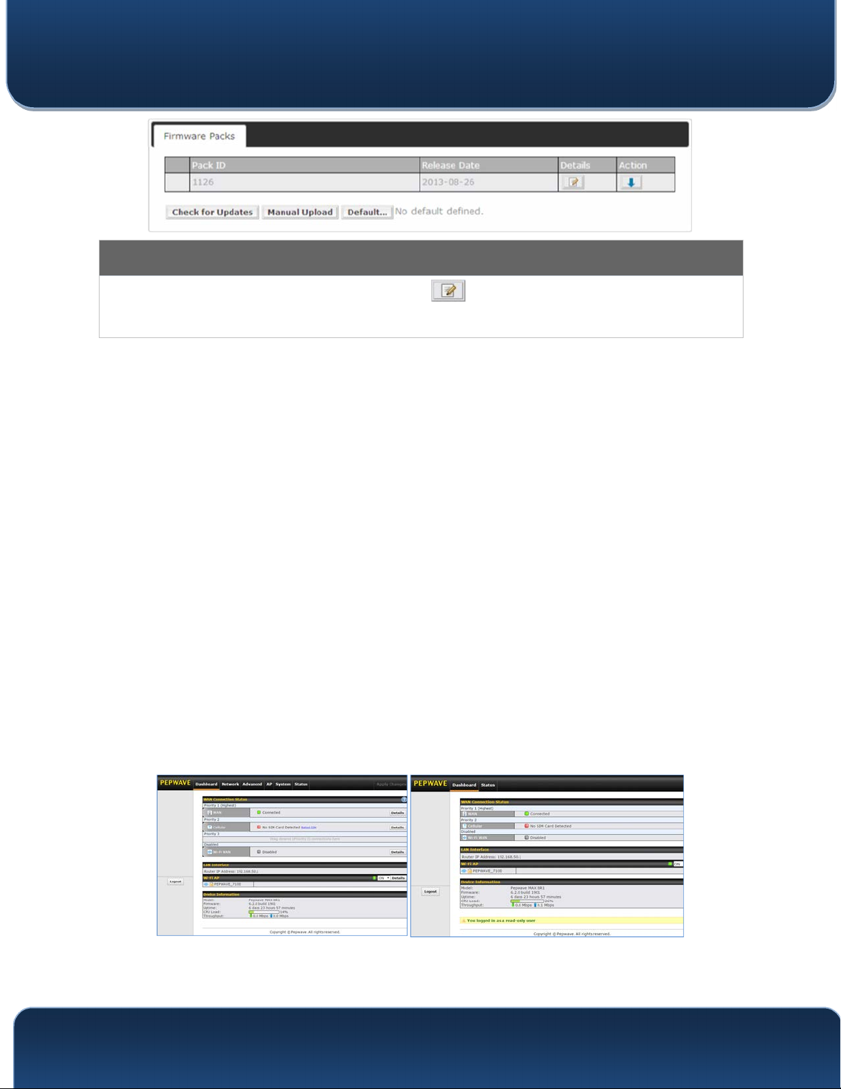
20.3 Toolbox
Tools for managing firmware packs can be found at AP>Toolbox.
http://www.pepwave.com 145 Copyright @ 2016 Pepwave
Pepwave MAX and Surf User Manual
Firmware Packs
Here, you can manage the firmware of your AP. Clicking on will result in information regarding each firmware
pack. To receive new firmware packs, you can click Check for Updates to download new packs, or you can click
Manual Upload to manually upload a firmware pack. Click Default to define which firmware pack is default.
21 System Settings
21.1 Admin Security
There are two types of user accounts available for accessing the web admin:
admin and user. They represent two user levels: the admin level has full administration
access, while the user level is read-only. The user level can access only the device's
status information; users cannot make any changes on the device.
Admin account UI User account UI
http://www.pepwave.com 146 Copyright @ 2016 Pepwave
Pepwave MAX and Surf User Manual
A web login session will be logged out automatically
when it has been idle longer than
the Web Session Timeout. Before the session expires, you may click the Logout
button in the web admin to exit the session.
0 hours 0 minutes signifies an unlimited session time. This setting should be used only
in special situations, as it will lower the system security level if users do not log out
before closing the browser. The default is 4 hours, 0 minutes.
For security reasons, after logging in to the web admin Interface for the first time, it is
recommended to change the administrator password. Configuring the administration
interface to be accessible only from the LAN can further improve system security.
Administrative settings configuration is located at System>Admin Security.
http://www.pepwave.com 147 Copyright @ 2016 Pepwave

Pepwave MAX and Surf User Manual
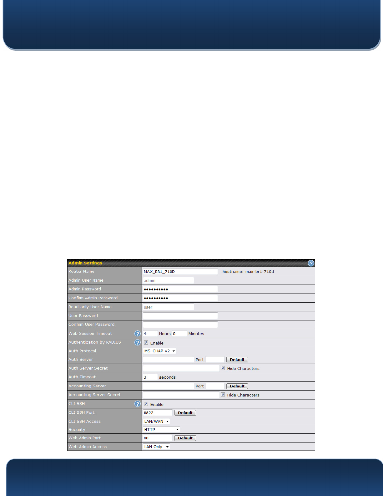
Admin Settings
This field allows you to define a name for this Pepwave router. By default, Router Name
Router Name
is set as MAX_XXXX or Surf_SOHO_XXXX, where XXXX refers to the last 4 digits of the
unit’s serial number.
Admin User
Name
Admin
Password
Confirm Admin
Password
Read-only User
Name
User Password
Confirm User
Password
Web Session
Timeout
Authentication
by RADIUS
Admin User Name is set as admin by default, but can be changed, if desired.
This field allows you to specify a new administrator password.
This field allows you to verify and confirm the new administrator password.
Read-only User Name is set as user by default, but can be changed, if desired.
This field allows you to specify a new user password. Once the user password is set, the
read-only user feature will be enabled.
This field allows you to verify and confirm the new user password.
This field specifies the number of hours and minutes that a web session can remain idle
before the Pepwave router terminates its access to the web admin interface. By default, it
is set to 4 hours.
With this box is checked, the web admin will authenticate using an external RADIUS
server. Authenticated users are treated as either "admin" with full read-write permission
or “user” with read-only access. Local admin and user accounts will be disabled. When
the device is not able to communicate with the external RADIUS server, local accounts
will be enabled again for emergency access. Additional authentication options will be
available once this box is checked.
Auth Protocol
Auth Server
Auth Server
This specifies the authentication protocol used. Available options are MS-CHAP v2 and
PAP.
This specifies the access address and port of the external RADIUS server.
This field is for entering the secret key for accessing the RADIUS server.
Secret
Auth Timeout
Accounting
This option specifies the time value for authentication timeout.
This specifies the access address and port of the external accounting server.
Server
Accounting
This field is for entering the secret key for accessing the accounting server.
Server Secret
Network
Connection
CLI SSH
This option is for specifying the network connection to be used for authentication. Users
can choose from LAN, WAN, and VPN connections.
The CLI (command line interface) can be accessed via SSH. This field enables CLI
http://www.pepwave.com 148 Copyright @ 2016 Pepwave

Pepwave MAX and Surf User Manual
support. For additional information regarding CLI, please refer to Section 21.16.
CLI SSH Port
CLI SSH
Access
Security
Web Admin
Port
Web Admin
Access
This field determines the port on which clients can access CLI SSH.
This menu allows you to choose between granting access to LAN and WAN clients, or to
LAN clients only.
This option is for specifying the protocol(s) through which the web admin interface can be
accessed:
• HTTP
• HTTPS
• HTTP/HTTPS
This field is for specifying the port number on which the web admin interface can be
accessed.
This option is for specifying the network interfaces through which the web admin interface
can be accessed:
• LAN only
• LAN/WAN
If LAN/WAN is chosen, the WAN Connection Access Settings form will be displayed.
Allowed
Source IP
Subnets
WAN Connection Access Settings
This field allows you to restrict web admin access only from defined IP subnets.
• Any - Allow web admin accesses to be from anywhere, without IP address
restriction.
• Allow access from the following IP subnets only - Restrict web admin access only
from the defined IP subnets. When this is chosen, a text input area will be displayed
beneath:
The allowed IP subnet addresses should be entered into this text area. Each IP subnet
must be in form of w.x.y.z/m, where w.x.y.z is an IP address (e.g., 192.168.0.0), and m is
the subnet mask in CIDR format, which is between 0 and 32 inclusively (For example,
192.168.0.0/24).
To define multiple subnets, separate each IP subnet one in a line. For example:
http://www.pepwave.com 149 Copyright @ 2016 Pepwave

Pepwave MAX and Surf User Manual
• 192.168.0.0/24
• 10.8.0.0/16
Allowed WAN
IP Address(es)
This is to choose which WAN IP address(es) the web server should listen on.
http://www.pepwave.com 150 Copyright @ 2016 Pepwave

Pepwave MAX and Surf User Manual
21.2 Firmware
Pepwave router firmware is upgradeable through the web admin interface. Firmware
upgrade functionality is located at System>Firmware.
There are two ways to upgrade the unit. The first method is through an online download.
The second method is to upload a firmware file manually.
To perform an online download, click on the Check for Firmware button. The Pepwave
router will check online for new firmware. If new firmware is available, the Pepwave
router will automatically download the firmware. The rest of the upgrade process will be
automatically initiated.
You may also download a firmware image from the Peplink website and update the unit
manually. To update using a firmware image, click Choose File to select the firmware
file from the local computer, and then click Manual Upgrade to send the firmware to the
Pepwave router. It will then automatically initiate the firmware upgrade process.
Please note that all Peplink devices can store two different firmware versions in two
different partitions. A firmware upgrade will always replace the inactive partition. If you
want to keep the inactive firmware, you can simply reboot your device with the inactive
firmware and then perform the firmware upgrade.
Important Note
The firmware upgrade process may not necessarily preserve the previous configuration, and the behavior varies on
a case-by-case basis. Consult the release notes for the particular firmware version before installing. Do not
disconnect the power during firmware upgrade process. Do not attempt to upload a non-firmware file or a firmware
file that is not supported by Peplink. Upgrading the Pepwave router with an invalid firmware file will damage the unit
and may void the warranty.
Important Note
If the firmware is rolled back from 5.x to 4.x, the configurations will be lost.
http://www.pepwave.com 151 Copyright @ 2016 Pepwave
Pepwave MAX and Surf User Manual
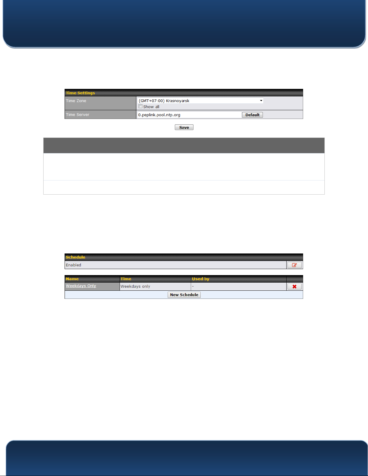
21.3 Time
Time Settings enables the system clock of the Pepwave router to be synchronized with
a specified time server. Time settings are located at System>Time.
Time Settings
This specifies the time zone (along with the corresponding Daylight Savings Time scheme).
Time Zone
The Time Zone value affects the time stamps in the Pepwave router’s event log and e-mail
notifications. Check Show all to show all time zone options.
Time Server
This setting specifies the NTP network time server to be utilized by the Pepwave router.
21.4 Schedule
Enable and disable different functions (such as WAN connections, outbound policy, and
firewalls at different times, based on a user-scheduled configuration profile. The settings
for this are located at System > Schedule
Enable scheduling, and then click on your schedule name or on the New Schedule button
to begin.
http://www.pepwave.com 152 Copyright @ 2016 Pepwave
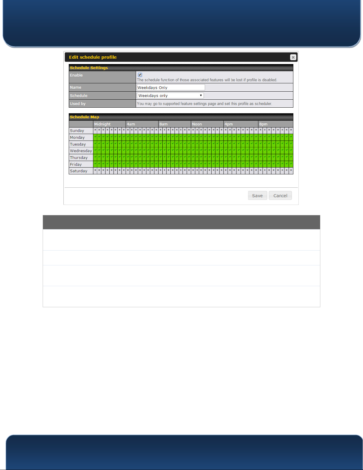
Pepwave MAX and Surf User Manual
Edit Schedule Profile
Enabling
Name
Schedule
Schedule Map
Click this checkbox to enable this schedule profile. Note that if this is disabled, then any
associated features will also have their scheduling disabled.
Enter your desired name for this particular schedule profile.
Click the drop-down menu to choose pre-defined schedules as your starting point. Please
note that upon selection, previous changes on the schedule map will be deleted.
Click on the desired times to enable features at that time period. You can hold your mouse
for faster entry.
21.5 Email Notification
Email notification functionality provides a system administrator with up-to-date
information on network status. The settings for configuring email notifications are found
at System>Email Notification.
http://www.pepwave.com 153 Copyright @ 2016 Pepwave

Pepwave MAX and Surf User Manual
Email
Notification
SMTP Server
SSL Encryption
SMTP Port
SMTP User
Name /
Password
Confirm SMTP
Password
Sender’s Email
Address
Email Notification Settings
This setting specifies whether or not to enable email notification. If Enable is checked, the
Pepwave router will send email messages to system administrators when the WAN status
changes or when new firmware is available. If Enable is not checked, email notification is
disabled and the Pepwave router will not send email messages.
This setting specifies the SMTP server to be used for sending email. If the server requires
authentication, check Require authentication.
Check the box to enable SMTPS. When the box is checked, SMTP Port will be changed to
465 automatically.
This field is for specifying the SMTP port number. By default, this is set to 25; when SSL
Encryption is checked, the default port number will be set to 465. You may customize the
port number by editing this field. Click Default to restore the number to its default setting.
This setting specifies the SMTP username and password while sending email. These
options are shown only if Require authentication is checked in the SMTP Server setting.
This field allows you to verify and confirm the new administrator password.
This setting specifies the email address the Pepwave router will use to send reports.
Recipient’s
Email Address
This setting specifies the email address(es) to which the Pepwave router will send email
notifications. For multiple recipients, separate each email addresses using the enter key.
After you have finished setting up email notifications, you can click the Test Email
Notification button to test the settings before saving. After Test Email Notification is
http://www.pepwave.com 154 Copyright @ 2016 Pepwave

Pepwave MAX and Surf User Manual
clicked, you will see this screen to confirm the set
tings:
Click Send Test Notification to confirm. In a few seconds, you will see a message with
detailed test results.
21.6 Event Log
Event log functionality enables event logging at a specified remote syslog server. The
settings for configuring the remote system log can be found at System>Event Log.
Event Log Settings
Remote Syslog
Remote Syslog
Host
This setting specifies whether or not to log events at the specified remote syslog server.
This setting specifies the IP address or hostname of the remote syslog server.
http://www.pepwave.com 155 Copyright @ 2016 Pepwave

Pepwave MAX and Surf User Manual
The Pepwave router can also send push notifications to mobile devices that have our
Mobile Router Utility installed. Check the box to activate this feature.
Push Events
For more information on the Router Utility, go to:
www.peplink.com/products/router-utility
http://www.pepwave.com 156 Copyright @ 2016 Pepwave

Pepwave MAX and Surf User Manual
21.7 SNMP
SNMP or simple network management protocol is an open standard that can be used to
collect information about the Pepwave router. SNMP configuration is located at
System>SNMP.
SNMP Settings
SNMP Device
Name
SNMP Port
SNMPv1
SNMPv2
SNMPv3
This field shows the router name defined at System>Admin Security.
This option specifies the port which SNMP will use. The default port is 161.
This option allows you to enable SNMP version 1.
This option allows you to enable SNMP version 2.
This option allows you to enable SNMP version 3.
To add a community for either SNMPv1 or SNMPv2, click the Add SNMP Community
button in the Community Name table, upon which the following screen is displayed:
http://www.pepwave.com 157 Copyright @ 2016 Pepwave

Pepwave MAX and Surf User Manual
SNMP Community Settings
Community
Name
Allowed Source
Subnet
Address
This setting specifies the SNMP community name.
This setting specifies a subnet from which access to the SNMP server is allowed. Enter
subnet address here (e.g., 192.168.1.0) and select the appropriate subnet mask.
To define a user name for SNMPv3, click Add SNMP User in the SNMPv3 User Name
table, upon which the following screen is displayed:
SNMPv3 User Settings
User Name
Authentication
Protocol
Privacy Protocol
This setting specifies a user name to be used in SNMPv3.
This setting specifies via a drop-down menu one of the following valid authentication
protocols:
• NONE
• MD5
• SHA
When MD5 or SHA is selected, an entry field will appear for the password.
This setting specifies via a drop-down menu one of the following valid privacy
protocols:
• NONE
• DES
When DES is selected, an entry field will appear for the password.
http://www.pepwave.com 158 Copyright @ 2016 Pepwave

Pepwave MAX and Surf User Manual
21.8 InControl
InControl is a cloud-based service which allows you to manage all of your Peplink and
Pepwave devices with one unified system. With it, you can generate reports, gather
statistics, and configure your devices automatically. All of this is now possible with
InControl.
When this check box is checked, the device's status information will be sent to the Peplink
InControl system. This device's usage data and configuration will be sent to the system if
you enable the features in the system.
Alternately, you could also privately host InControl. Simply check the box beside the
“Privately Host InControl” open, and enter the IP Address of your InControl Host.
You can sign up for an InControl account at https://incontrol2.peplink.com/. You can
register your devices under the account, monitor their status, see their usage reports,
and receive offline notifications.
21.9 Configuration
http://www.pepwave.com 159 Copyright @ 2016 Pepwave
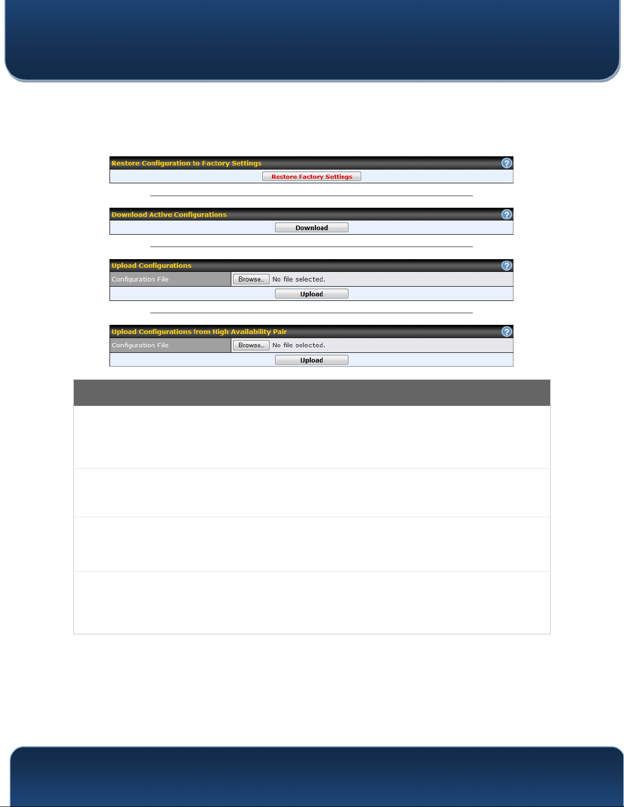
Pepwave MAX and Surf User Manual
Backing up Pepwave router settings immediately after
successful completion of initial
setup is strongly recommended. The functionality to download and upload Pepwave
router settings is found at System>Configuration. Note that available options vary by
model.
Restore
Configuration
to Factory
Settings
Download
Active
Configurations
Upload
Configurations
Upload
Configurations
from High
Availability Pair
Configuration
The Restore Factory Settings button is to reset the configuration to factory default
settings. After clicking the button, you will need to click the Apply Changes button on the
top right corner to make the settings effective.
Click Download to backup the current active settings.
To restore or change settings based on a configuration file, click Choose File to locate the
configuration file on the local computer, and then click Upload. The new settings can then
be applied by clicking the Apply Changes button on the page header, or you can cancel
the procedure by pressing discard on the main page of the web admin interface.
In a high availability (HA) configuration, a Pepwave router can quickly load the configuration
of its HA counterpart. To do so, click the Upload button. After loading the settings,
configure the LAN IP address of the Pepwve router so that it is different from the HA
counterpart.
http://www.pepwave.com 160 Copyright @ 2016 Pepwave
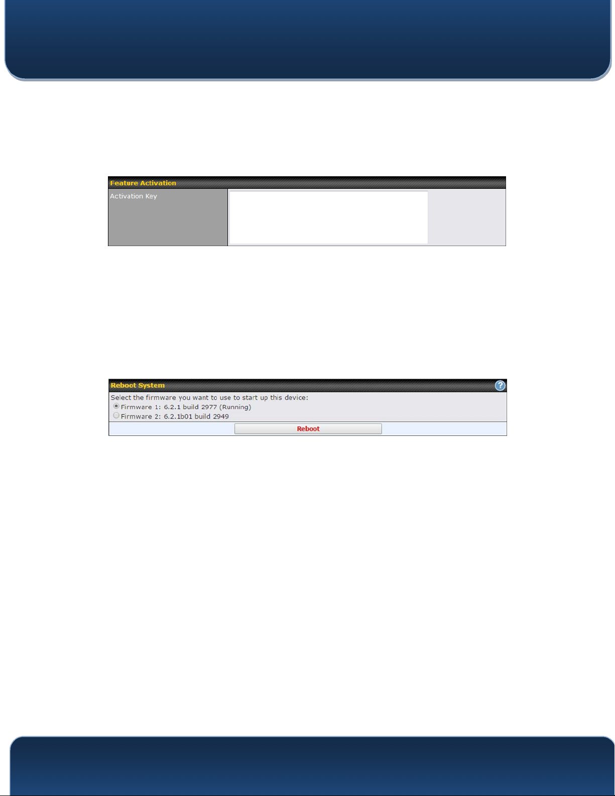
Pepwave MAX and Surf User Manual
21.10 Feature Add-ons
Some Pepwave routers have features that can be activated upon purchase. Once the
purchase is complete, you will receive an activation key. Enter the key in the Activation
Key field, click Activate, and then click Apply Changes.
21.11 Reboot
This page provides a reboot button for restarting the system. For maximum reliability,
the Pepwave router can equip with two copies of firmware. Each copy can be a different
version. You can select the firmware version you would like to reboot the device with.
The firmware marked with (Running) is the current system boot up firmware.
Please note that a firmware upgrade will always replace the inactive firmware
partition.
http://www.pepwave.com 161 Copyright @ 2016 Pepwave

Pepwave MAX and Surf User Manual
21.12 Ping
The ping test tool sends pings through a specified Ethernet interface or a
SpeedFusionTM VPN connection. You can specify the number of pings in the field
Number of times, to a maximum number of 10 times. Packet Size can be set to a
maximum of 1472 bytes. The ping utility is located at System>Tools>Ping, illustrated
below:
Tip
A system administrator can use the ping utility to manually check the connectivity of a particular LAN/WAN
connection.
http://www.pepwave.com 162 Copyright @ 2016 Pepwave

Pepwave MAX and Surf User Manual
21.13 Traceroute Test
The traceroute test tool traces the routing path to the destination through a particular
Ethernet interface or a SpeedFusion
TM
connection. The traceroute test utility is located
at System>Tools>Traceroute.
Tip
A system administrator can use the traceroute utility to analyze the connection path of a LAN/WAN connection.
21.14 PepVPN Test
The PepVPN Test tool can help to test the throughput between different VPN peers.
You can define the Test Type, Direction, and Duration of the test, and press Go! to
perform the throughput test. The VPN test utility is located at System>Tools>PepVPN
Test, illustrated as follows:
http://www.pepwave.com 163 Copyright @ 2016 Pepwave

Pepwave MAX and Surf User Manual
21.15 Wake-on-LAN
Peplink routers can send special “magic packets” to any client specified from the Web UI. To
access this feature, navigate to System > Tools > Wake-on-LAN
Select a client from the drop-down list and click Send to send a “magic packet”
21.16 CLI (Command Line Interface Support)
The CLI (command line interface) can be accessed via SSH. This field enables CLI
support. The below settings specify which TCP port and which interface(s) should
accept remote SSH CLI access. The user name and password used for remote SSH
CLI access are the same as those used for web admin access.
http://www.pepwave.com 164 Copyright @ 2016 Pepwave

Pepwave MAX and Surf User Manual
22 Status
22.1 Device
System information is located at Status>Device.
Router Name
Model
Product Code
Hardware
Revision
Serial Number
Firmware
PepVPN
Version
Modem
Support
Version
System Information
This is the name specified in the Router Name field located at System>Admin Security.
This shows the model name and number of this device.
If your model uses a product code, it will appear here.
This shows the hardware version of this device.
This shows the serial number of this device.
This shows the firmware version this device is currently running.
This shows the current PepVPN version.
This shows the modem support version. For a list of supported modems, click Modem
Support List.
Host Name
Uptime
System Time
Diagnostic
Report
The host name assigned to the Pepwave router appears here.
This shows the length of time since the device has been rebooted.
This shows the current system time.
The Download link is for exporting a diagnostic report file required for system investigation.
http://www.pepwave.com 165 Copyright @ 2016 Pepwave

Pepwave MAX and Surf User Manual
Remote
A
ssistance
Click Turn on to enable remote assistance.
The second table shows the MAC address of each LAN/WAN interface connected. To
view your device’s End User License Agreement (EULA), click .
Important Note
If you encounter issues and would like to contact the Pepwave Support Team (http://www.pepwave.com/contact/),
please download the diagnostic report file and attach it along with a description of your issue.
In Firmware 5.1 or before, the diagnostic report file can be obtained at System>Reboot.
22.1.1 GPS Data
The MAX HD2 and HD2 IP67 automatically store up to seven days of GPS location data
in GPS eXchange format (GPX). To review this data using third-party applications, click
Status>Device and then download your GPX file.
The Pepwave MAX BR1, HD2, and HD2 IP67 export real-time location data in NMEA
format through the LAN IP address at TCP port 60660. It is accessible from the LAN or
over a SpeedFusion connection. To access the data via a virtual serial port, install a
virtual serial port driver. Visit http://www.peplink.com/index.php?view=faq&id=294 to
download the driver.
http://www.pepwave.com 166 Copyright @ 2016 Pepwave

Pepwave MAX and Surf User Manual
22.2 Active Sessions
Information on active sessions can be found at Status>Active Sessions>Overview.
This screen displays the number of sessions initiated by each application. Click on each
service listing for additional information. This screen also indicates the number of
sessions initiated by each WAN port. In addition, you can see which clients are initiating
the most sessions.
http://www.pepwave.com 167 Copyright @ 2016 Pepwave

Pepwave MAX and Surf User Manual
You can also perform a filtered search for specific
sessions. You can filter by subnet,
port, protocol, and interface. To perform a search, navigate to Status>Active
Sessions>Search.
This Active Sessions section displays the active inbound/outbound sessions of each
WAN connection on the Pepwave router. A filter is available to sort active session
information. Enter a keyword in the field or check one of the WAN connection boxes for
filtering.
http://www.pepwave.com 168 Copyright @ 2016 Pepwave

Pepwave MAX and Surf User Manual
22.3 Client List
The client list table is located at Status>Client List. It lists DHCP and online client IP
addresses, names (retrieved from the DHCP reservation table or defined by users),
current download and upload rate, and MAC address.
Clients can be imported into the DHCP reservation table by clicking the button on
the right. You can update the record after import by going to Network>LAN.
TM
If the PPTP server (see Section 19.2), SpeedFusion
controller (see Section 20) is enabled, you may see the corresponding connection
name listed in the Name field.
(see Section 12.1), or AP
22.4 WINS Client
The WINS client list table is located at Status>WINS Client.
The WINS client table lists the IP addresses and names of WINS clients. This option will
only be available when you have enabled the WINS server (navigation:
Network>Interfaces>LAN). The names of clients retrieved will be automatically
matched into the Client List (see previous section). Click Flush All to flush all WINS
client records.
http://www.pepwave.com 169 Copyright @ 2016 Pepwave
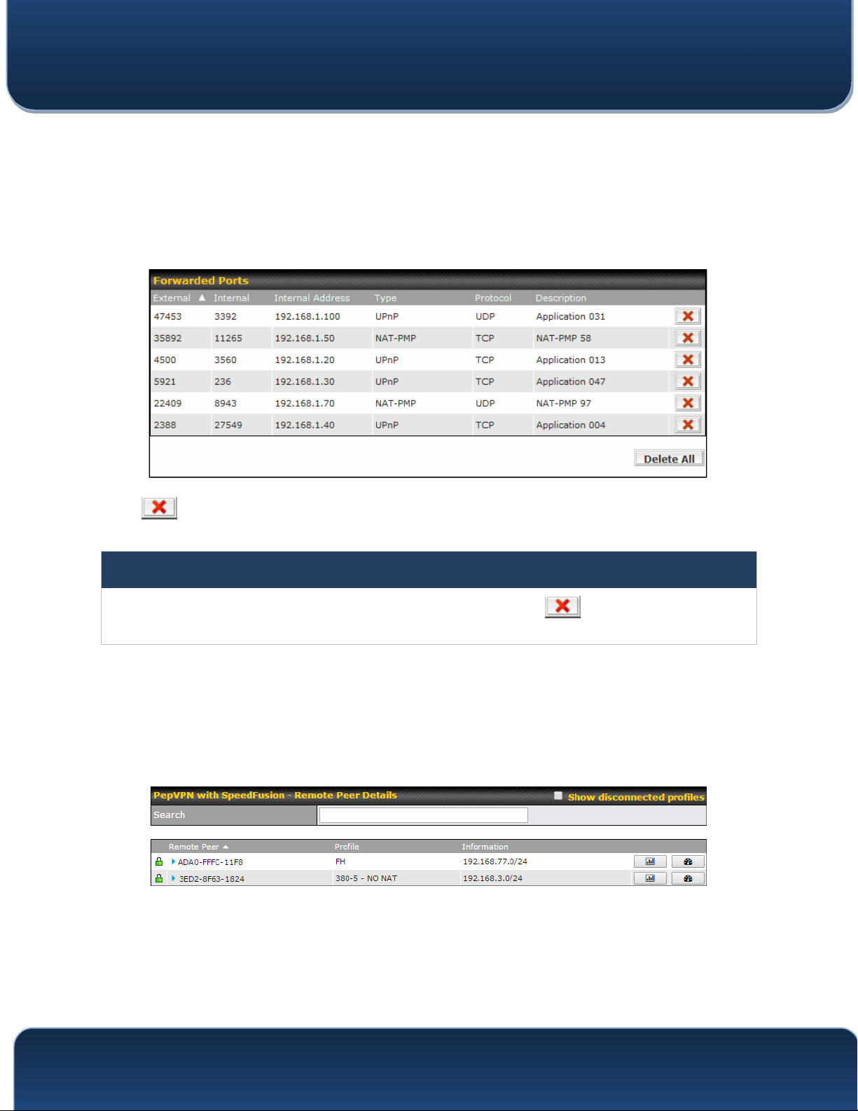
Pepwave MAX and Surf User Manual
22.5 UPnP / NAT-PMP
The table that shows the forwarded ports under UPnP and NAT-PMP protocols is
located at Status>UPnP/NAT-PMP. This section appears only if you have enabled
UPnP / NAT-PMP as mentioned in Section 16.1.1.
lick to delete a single UPnP / NAT-PMP record in its corresponding row. To
C
delete all records, click Delete All on the right-hand side below the table.
Important Note
UPnP / NAT-PMP records will be deleted immediately after clicking the button or Delete All, without the
need to click Save or Confirm.
22.6 SpeedFusion Status
Current SpeedFusionTM status information is located at Status>SpeedFusionTM.
Details about SpeedFusion
Click on the corresponding peer name to explore the WAN connection(s) status and
subnet information of each VPN peer.
TM
connection peers appears as below:
http://www.pepwave.com 170 Copyright @ 2016 Pepwave

Pepwave MAX and Surf User Manual
C
lick the button for a chart displaying real-time throughput, latency, and drop-
rate information for each WAN connection.
When pressing the button, the following menu will appear:
http://www.pepwave.com 171 Copyright @ 2016 Pepwave

Pepwave MAX and Surf User Manual
A
fter clicking the icon, the following menu appears:
Select the L2 protocol (TCP/UDP), direction, and duration and click the Start button to
begin the general throughput test.
http://www.pepwave.com 172 Copyright @ 2016 Pepwave

Pepwave MAX and Surf User Manual
T
he bandwidth bonding feature of PepVPN occurs when multiple WAN lines from one
end merge with multiple WAN lines from the other end. For this to happen, each WAN
line needs to form a connection with all the WAN lines on the opposite end. The function
of the PepVPN analyzer is to report the throughput, packet loss, and latency of all
possible combinations of connections. Please note that the PepVPN Analyzer will
temporarily interrupt VPN connectivity and will restore after test.
After clicking the icon, the analyzer will require several minutes to perform its analysis
depending the number of WAN links in the SpeedFusion
complete, the report will appear:
TM
Tunnel. Once the test the
"O" indicates that specific WAN / Tunnel is active for that particular test.
"Tx Avg." is the averaged throughput across the full 10 seconds time, while "Tx Max." is
the averaged throughput of the fastest 30% of time.
http://www.pepwave.com 173 Copyright @ 2016 Pepwave

Pepwave MAX and Surf User Manual
22.7 Event Log
Event log information is located at Status>Event Log.
The log section displays a list of events that has taken place on the Pepwave router.
Check Auto Refresh to refresh log entries automatically. Click the Clear Log button to
clear the log.
22.8 Bandwidth
This section shows bandwidth usage statistics and is located at Status>Bandwidth.
Bandwidth usage at the LAN while the device is switched off (e.g., LAN bypass) is
neither recorded nor shown.
http://www.pepwave.com 174 Copyright @ 2016 Pepwave

Pepwave MAX and Surf User Manual
22.8.1 Real-Time
T
he Data transferred since installation table indicates how much network traffic has
been processed by the device since the first bootup. The Data transferred since last
reboot table indicates how much network traffic has been processed by the device
since the last bootup.
http://www.pepwave.com 175 Copyright @ 2016 Pepwave
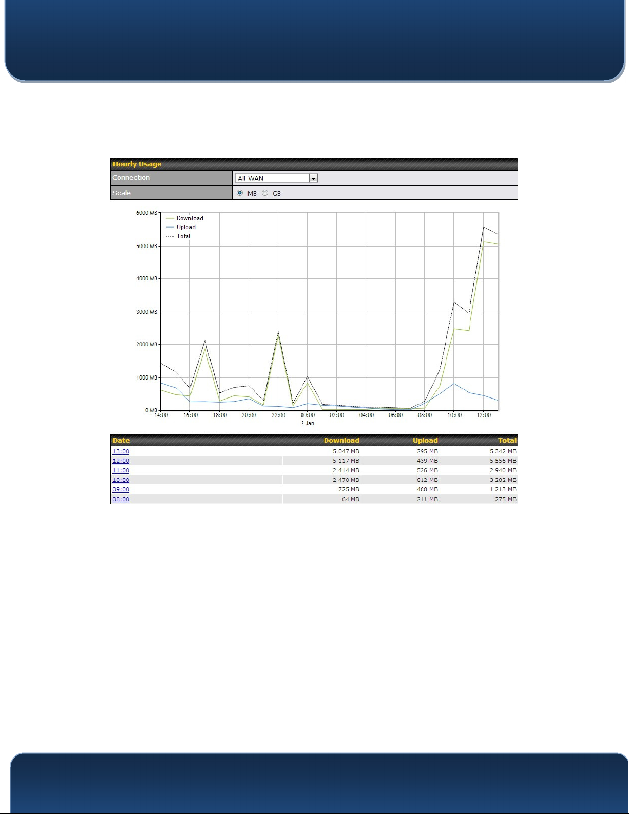
Pepwave MAX and Surf User Manual
22.8.2 Hourly
T
his page shows the hourly bandwidth usage for all WAN connections, with the option
of viewing each individual connection. Select the desired connection to check from the
drop-down menu.
22.8.3 Daily
http://www.pepwave.com 176 Copyright @ 2016 Pepwave

Pepwave MAX and Surf User Manual
This page shows the daily bandwidth usage for all WA
N connections, with the option of
viewing each individual connection.
Select the connection to check from the drop-down menu. If you have enabled the
Bandwidth Monitoring feature, the Current Billing Cycle table for that WAN
connection will be displayed.
Click on a date to view the client bandwidth usage of that specific date. This feature is
not available if you have selected to view the bandwidth usage of only a particular WAN
connection. The scale of the graph can be set to display megabytes (MB) or gigabytes
(GB).
All WAN Daily Bandwidth Usage
http://www.pepwave.com 177 Copyright @ 2016 Pepwave

Pepwave MAX and Surf User Manual
22.8.4 Monthly
T
his page shows the monthly bandwidth usage for each WAN connection. If you have
enabled the Bandwidth Monitoring feature, you can check the usage of each
particular connection and view the information by Billing Cycle or by Calendar Month.
Click the first two rows to view the client bandwidth usage in the last two months. This
feature is not available if you have chosen to view the bandwidth of an individual WAN
connection. The scale of the graph can be set to display megabytes (MB) or gigabytes
(GB).
All WAN Monthly Bandwidth Usage
http://www.pepwave.com 178 Copyright @ 2016 Pepwave

Pepwave MAX and Surf User Manual
E
thernet WAN Monthly Bandwidth Usage
Tip
By default, the scale of data size is in MB. 1GB equals 1024MB.
http://www.pepwave.com 179 Copyright @ 2016 Pepwave

Pepwave MAX and Surf User Manual
Appendix A. Restoration of Factory Defaults
To restore the factory default settings on a Pepwave router, follow the steps below:
1. Locate the reset button on the front or back panel of the Pepwave router.
2. With a paper clip, press the reset button and hold it for at least 10 seconds, until
the unit reboots itself.
After the Pepwave router finishes rebooting, the factory default settings will be restored.
Important Note
All previous configurations and bandwidth usage data will be lost after restoring factory default settings. Regular
backup of configuration settings is strongly recommended.
http://www.pepwave.com 180 Copyright @ 2016 Pepwave

Pepwave MAX and Surf User Manual
Appendix B: Declaration
1. The device supports time division technology
2. Federal Communication Commission and Industry Canada Interference
Statement
This equipment has been tested and found to comply with the limits for a Class A digital
device, pursuant to part 15 of the FCC Rules. These limits are designed to provide
reasonable protection against harmful interference when the equipment is operated in a
commercial environment. This equipment generates, uses, and can radiate radio
frequency energy and, if not installed and used in accordance with the instruction
manual, may cause harmful interference to radio communications. Operation of this
equipment in a residential area is likely to cause harmful interference in which case the
user will be required to correct the interference at his own expense.
Caution: Any changes or modifications not expressly approved by the party responsible
for compliance could void the user's authority to operate this equipment.
This transmitter must not be co-located or operating in conjunction with any other
antenna or transmitter.
Operations in the 5.15-5.25GHz band are restricted to indoor usage only.
IMPORTANT NOTE
FCC Radiation Exposure Statement (for MAX BR1 mini)
This equipment complies with FCC radiation exposure limits set forth for an uncontrolled
environment. This equipment should be installed and operated with minimum distance
25cm between the radiator & your body.
This transmitter must not be co-located or operating in conjunction with any other antenna
or transmitter.
The availability of some specific channels and/or operational frequency bands are country
dependent and are firmware programmed at the factory to match the intended destination.
FCC Radiation Exposure Statement (for MAX Hotspot / HD2 IP67/ BR1/ Surf SOHO)
This equipment complies with FCC radiation exposure limits set forth for an uncontrolled
environment. This equipment should be installed and operated with minimum distance
20cm between the radiator & your body.
FCC Radiation Exposure Statement (for MAX On-The-Go)
This equipment complies with FCC radiation exposure limits set forth for an uncontrolled
environment.
http://www.pepwave.com 181 Copyright @ 2016 Pepwave

Pepwave MAX and Surf User Manual
. 20cm minimum when the product is operated alone witho
1
plug-in 3G USB dongle device.
2. 65cm minimum when the product is operated with a plug-in 3G USB device which
has maximum of 7W ERP output power.
3. For co-transmission scenario which is not covered above, please consult the RF
technician or device supplier.
This transmitter must not be co-located or operating in conjunction with any other
antenna or transmitter.
The availability of some specific channels and/or operational frequency bands are
country dependent and are firmware programmed at the factory to match the intended
destination.
ut co-transmitting with a
http://www.pepwave.com 182 Copyright @ 2016 Pepwave

Pepwave MAX and Surf User Manual
Industry Canada Statement (for MAX Hotspot/ Surf SOHO/ MAX HD2 / MAX BR1 mini)
This device complies with Industry Canada license-exempt RSS standard(s). Operation
is subject to the following two conditions: (1) this device may not cause interference, and
(2) this device must accept any interference, including interference that may cause
undesired operation of the device.
Le présent appareil est conforme aux CNR d'Industrie Canada applicables aux appareils
radio exempts de licence. L'exploitation est autorisée aux deux conditions suivantes : (1)
l'appareil ne doit pas produire de brouillage, et (2) l'utilisateur de l'appareil doit accepter
tout brouillage radioélectrique subi, même si le brouillage est susceptible d'en
compromettre le fonctionnement.
To maintain compliance with the RF exposure guidelines, place the unit at least 20cm
from nearby persons.
Mise en garde_: Pour assurer la conformité aux directives relatives à l'exposition aux
fréquences radio, le jouet doit êtreplacé à au moins 20_cm des personnes à proximité.
Caution :
(i) the device for operation in the band 5150-5250 MHz is only for indoor use to reduce
the potential for harmful interference to co-channel mobile satellite systems;
(ii) the maximum antenna gain permitted for devices in the band 5725-5850 MHz shall
e such that the equipment still complies with the e.i.r.p. limits specified for point-to-point
b
and non-point-to-point operation as appropriate; and
(iii) Users should also be advised that high-power radars are allocated as primary users
(i.e. priority users) of the bands 5650-5850 MHz and that these radars could cause
interference and/or damage to LE-LAN devices.
http://www.pepwave.com 183 Copyright @ 2016 Pepwave

Pepwave MAX and Surf User Manual
A
vertissement:
(i) les dispositifs fonctionnant dans la bande 5150-5250 MHz sont réservés uniquement
pour une utilisation à l’intérieur afin de réduire les risques de brouillage préjudiciable
aux systèmes de satellites mobiles utilisant les mêmes canaux;
le gain maximal d'antenne permis (pour les dispositifs utilisant la bande de 5725 à 5 850
(ii)
MHz) doit être conforme à la limite de la p.i.r.e. spécifiée pour l'exploitation point à point et
l’exploitation non point à point, selon le cas;
(iii) De plus, les utilisateurs devraient aussi être avisés que les utilisateurs de radars de
haute puissance sont désignés utilisateurs principaux (c.-à-d., qu’ils ont la priorité) pour
les bandes 5650-5850 MHz et que ces radars pourraient causer du brouillage et/ou des
dommages aux dispositifs LAN-EL.
Radiation Exposure Statement:
This equipment complies with ISED radiation exposure limits set forth for an uncontrolled
environment. This equipment should be installed and operated with minimum distance
20cm between the radiator & your body.
Déclaration d'exposition aux radiations:
Cet équipement est conforme aux limites d'exposition aux rayonnements ISED établies
pour un environnement non contrôlé. Cet équipement doit être installé et utilisé avec un
minimum de 20 cm de distance entre la source de rayonnement et votre corps.
3. CE Statement for Pepwave Routers
Europe – EU Declaration of Conformity
This device complies with the essential requirements of the R&TTE Directive
1999/5/EC. The following test methods have been applied in order to prove
presumption of conformity with the essential requirements of the R&TTE Directive
1999/5/EC:
- EN 60950-1: 2006 + A11 : 2009+A1 : 2010+ A12: 2011
Safety of Information Technology Equipment
- EN50385 : 2002 / Article 3(1)(a)
Product standard to demonstrate the compliance of radio base stations and fixed
terminal stations for wireless telecommunication systems with the basic restrictions
or the reference levels related to human exposure to radio frequency
electromagnetic fields (110MHz - 40 GHz) - General public
http://www.pepwave.com 184 Copyright @ 2016 Pepwave

[Jméno výrobce]
Pepwave MAX and Surf User Manual
EN 300 328 V1.7.1: 2006
E
lectromagnetic compatibility and Radio spectrum Matters (ERM); Wideband
Transmission systems; Data transmission equipment operating in the 2,4 GHz ISM
band and using spread spectrum modulation techniques; Harmonized EN covering
essential requirements under article 3.2 of the R&TTE Directive
- EN 301 908-1 V5.2.1: 2011
lectromagnetic compatibility and Radio spectrum Matters (ERM); Base Stations
E
(BS), Repeaters and User Equipment (UE) for IMT-2000 Third-Generation cellular
networks; Part 1: Harmonized EN for IMT-2000, introduction and common
requirements, covering essential requirements of article 3.2 of the R&TTE Directive
- EN 301 511 V9.0.2: 2003
Global System for Mobile communications (GSM); Harmonized standard for mobile
stations in the GSM 900 and DCS 1800 bands covering essential requirements
under article 3.2 of the R&TTE directive (1999/5/EC)
- EN 301 489-1 V1.9.2: 2008
Electromagnetic compatibility and Radio Spectrum Matters (ERM); ElectroMagnetic
Compatibility (EMC) standard for radio equipment and services; Part 1: Common
technical requirements
- EN 301 489-7 V1.3.1: 2005
ElectroMagnetic compatibility and Radio spectrum Matters (ERM); ElectroMagnetic
Compatibility (EMC) standard for radio equipment ad services; Part 7: Specific
conditions for mobile and portable radio and ancillary equipment of digital cellular
radio telecommunications systems (GSM and DCS)
- EN 301 489-17 V2.2.1: 2012
lectromagnetic compatibility and Radio spectrum Matters (ERM); ElectroMagnetic
E
Compatibility (EMC) standard for radio equipment and services; Part 17: Specific
conditions for 2,4 GHz wideband transmission systems and 5 GHz high
performance RLAN equipment
- EN 301 489-24 V1.5.1: 2010
Electromagnetic compatibility and Radio Spectrum Matters (ERM); ElectroMagnetic
Compatibility (EMC) standard for radio equipment and services; Part 24: Specific
conditions for IMT-2000 CDMA Direct Spread (UTRA) for Mobile and portable (UE)
radio and ancillary equipment
Česky
Czech]
[
http://www.pepwave.com 185 Copyright @ 2016 Pepwave
0081
tímto prohlašuje, že tento [typ zařízení] je ve shodě se
základními požadavky a dalšími příslušnými ustanoveními směrnice 1999/5/ES.

[seadme tüüp
è
[Nome do fabricante]
Pepwave MAX and Surf User Manual
Dansk
[
Danish]
Undertegnede [fabrikantens navn] erklærer herved, at følgende udstyr [udstyrets
typebetegnelse] overholder de væsentlige krav og øvrige relevante krav i direktiv
1999/5/EF.
Deutsch
[German]
Hiermit erklärt [Name des Herstellers], dass sich das Gerät [Gerätetyp] in
Übereinstimmung mit den grundlegenden Anforderungen und den übrigen
einschlägigen Bestimmungen der Richtlinie 1999/5/EG befindet.
Eesti
[Estonian]
Käesolevaga kinnitab [tootja nimi = name of manufacturer] seadme
= type of equipment] vastavust direktiivi 1999/5/EÜ põhinõuetele ja nimetatud
direktiivist tulenevatele teistele asjakohastele sätetele.
English Hereby, [name of manufacturer], declares that this [type of equipment] is in
compliance with the essential requirements and other relevant provisions of
Directive 1999/5/EC.
Español
[Spanish]
Por medio de la presente [nombre del fabricante] declara que el [clase de equipo]
cumple con los requisitos esenciales y cualesquiera otras disposiciones
aplicables o exigibles de la Directiva 1999/5/CE.
Ελληνική
[Greek]
ΜΕ ΤΗΝ ΠΑΡΟΥΣΑ [name of manufacturer] ∆ΗΛΩΝΕΙ ΟΤΙ [type of equipment]
ΣΥΜΜΟΡΦΩΝΕΤΑΙ ΠΡΟΣ ΤΙΣ ΟΥΣΙΩ∆ΕΙΣ ΑΠΑΙΤΗΣΕΙΣ ΚΑΙ ΤΙΣ ΛΟΙΠΕΣ
ΣΧΕΤΙΚΕΣ ∆ΙΑΤΑΞΕΙΣ ΤΗΣ Ο∆ΗΓΙΑΣ 1999/5/ΕΚ.
Français
[French]
Par la présente [nom du fabricant] déclare que l'appareil [type d'appareil] est
conforme aux exigences essentielles et aux autres dispositions pertinentes de la
directive 1999/5/CE.
Italiano
[Italian]
Con la presente [nome del costruttore] dichiara che questo [tipo di apparecchio]
conforme ai requisiti essenziali ed alle altre disposizioni pertinenti stabilite dalla
direttiva 1999/5/CE.
Latviski
[Latvian]
Ar šo [name of manufacturer / izgatavotāja nosaukums] deklarē, ka [type of
equipment / iekārtas tips] atbilst Direktīvas 1999/5/EK būtiskajām prasībām un
citiem ar to saistītajiem noteikumiem.
Lietuvių
[Lithuanian]
Šiuo [manufacturer name] deklaruoja, kad šis [equipment type] atitinka esminius
reikalavimus ir kitas 1999/5/EB Direktyvos nuostatas.
Hierbij verklaart [naam van de fabrikant] dat het toestel [type van toestel] in
Nederlands
[Dutch]
Malti
[Maltese]
overeenstemming is met de essentiële eisen en de andere relevante bepalingen
van richtlijn 1999/5/EG.
Hawnhekk, [isem tal-manifattur], jiddikjara li dan [il-mudel tal-prodott] jikkonforma
mal-ħtiġijiet essenzjali u ma provvedimenti oħrajn relevanti li hemm fid-Dirrettiva
1999/5/EC.
Magyar
[Hungarian]
Polski
[Polish]
Alulírott, [gyártó neve] nyilatkozom, hogy a [... típus]megfelel a vonatkozó
alapvetõ követelményeknek és az 1999/5/EC irányelv egyéb elõírásainak.
Niniejszym [nazwa producenta] oświadcza, że [nazwa wyrobu] jest zgodny z
zasadniczymi wymogami oraz pozostałymi stosownymi postanowieniami
Dyrektywy 1999/5/EC.
Português
[Portuguese]
os requisitos essenciais e outras disposições da Directiva 1999/5/CE.
declara que este [tipo de equipamento] está conforme com
http://www.pepwave.com 186 Copyright @ 2016 Pepwave

[Ime proizvajalca]
[Meno výrobcu]
[
de väsentliga egenskapskrav och övriga relevanta bestämmelser som framgår av
Pepwave MAX and Surf User Manual
Slovensko
[
Slovenian]
ostalimi relevantnimi določili direktive 1999/5/ES.
Slovensky
[Slovak]
Suomi
[Finnish]
všetky príslušné ustanovenia Smernice 1999/5/ES.
Valmistaja = manufacturer] vakuuttaa täten että [type of equipment = laitteen
tyyppimerkintä] tyyppinen laite on direktiivin 1999/5/EY oleellisten vaatimusten ja
sitä koskevien direktiivin muiden ehtojen mukainen.
Svenska
Härmed intygar [företag] att denna [utrustningstyp] står I överensstämmelse med
[Swedish]
direktiv 1999/5/EG.
4. NCC for Pepwave Routers
For MAX Transit
WLAN
[警語]
「電磁波曝露量
[
警語內容
MPE
標準值
]
izjavlja, da je ta [tip opreme] v skladu z bistvenimi zahtevami in
týmto vyhlasuje, že [typ zariadenia]spĺňa základné požiadavky a
1mW/cm2
,本產品使用時建議應距離人體
24 cm」
(1)
電磁波警語標示:「減少電磁波影響,請妥適使用」。 標示方式:必須標示於設備本體適當位置及設備
外包裝及使用說明書上。
低功率電波輻射性電機管理辦法
第十二條 經型式認證合格之低功率射頻電機,非經許可,公司、商號或使用者均不得擅自變更頻率、加大
功率或變更原設計之特性及功能。
第十四條 低功率射頻電機之使用不得影響飛航安全及干擾合法通信;經發現有干擾現象時,應立即停用,
並改善至無干擾時方得繼續使用。前項合法通信,指依電信法規定作業之無線電通信。低功率射頻電機須
忍受合法通信或工業、科學及醫療用電波輻射性電機設備之干擾。
本行動寬頻設備的行動寬頻頻段
警告使用者
此為甲類資訊技術設備,於居住環境中使用時,可能會造成射頻擾動,在此種情況下,使用者會被要求採
取某些適當的對策。
:
(LTE900/LTE1800)
http://www.pepwave.com 187 Copyright @ 2016 Pepwave

http://www.pepwave.com/partners/channel
-
Contact Us:
Sales
http://www.pepwave.com/contact/sales/
Support
http://www.pepwave.com/contact/
Business Development and
Partnerships
 Loading...