


This setting specifies the action to be taken by the router upon encountering traffic that
matches the both of the following:
● Source IP & port
Action
Event Logging
● Destination IP & port
With the value of Allow for the Action setting, the matching traffic passes through the
router (to be routed to the destination). If the value of the Action setting is set to Deny, the
matching traffic does not pass through the router (and is discarded).
This setting specifies whether or not to log matched firewall events. The logged messages
are shown on the page Status>Event Log. A sample message is as follows:
Aug 13 23:47:44 Denied CONN=Ethernet WAN SRC=20.3.2.1
DST=192.168.1.20 LEN=48 PROTO=TCP SPT=2260 DPT=80
● CONN: The connection where the log entry refers to
● SRC: Source IP address
● DST: Destination IP address
● LEN: Packet length
● PROTO: Protocol
● SPT: Source port
● DPT: Destination port
Click Save to store your changes. To create an additional firewall rule, click Add Rule and
repeat the above steps.
https://www.peplink.com 101 Copyright @ 2019 Peplink

To change a rule’s priority, simply drag and drop the rule:
● Hold the left mouse button on the rule.
● Move it to the desired position.
● Drop it by releasing the mouse button.
To remove a rule, click the button.
Rules are matched from top to the bottom. If a connection matches any one of the upper rules,
the matching process will stop. If none of the rules match the connection, the Default rule will
be applied.
The Default rule is Allow for both outbound and inbound access.
Tip
If the default inbound rule is set to Allow for NAT-enabled WANs, no inbound Allow firewall rules will be required
for inbound port forwarding and inbound NAT mapping rules. However, if the default inbound rule is set as Deny,
a corresponding Allow firewall rule will be required.
Intrusion Detection and DoS Prevention
The Balance can detect and prevent intrusions and denial-of-service (DoS) attacks from the
Internet. To turn on this feature, click , check the Enable check box for the Intrusion
Detection and DoS Prevention, and press the Save button.
When this feature is enabled, the Balance will detect and prevent the following kinds of
intrusions and denial-of-service attacks.
● Port scan
o NMAP FIN/URG/PSH
https://www.peplink.com 102 Copyright @ 2019 Peplink

o Xmas tree
o Another Xmas tree
o Null scan
o SYN/RST
o SYN/FIN
● SYN flood prevention
● Ping flood attack prevention
10.12.2 Content Blocking
https://www.peplink.com 103 Copyright @ 2019 Peplink
https://www.peplink.com 104 Copyright @ 2019 Peplink

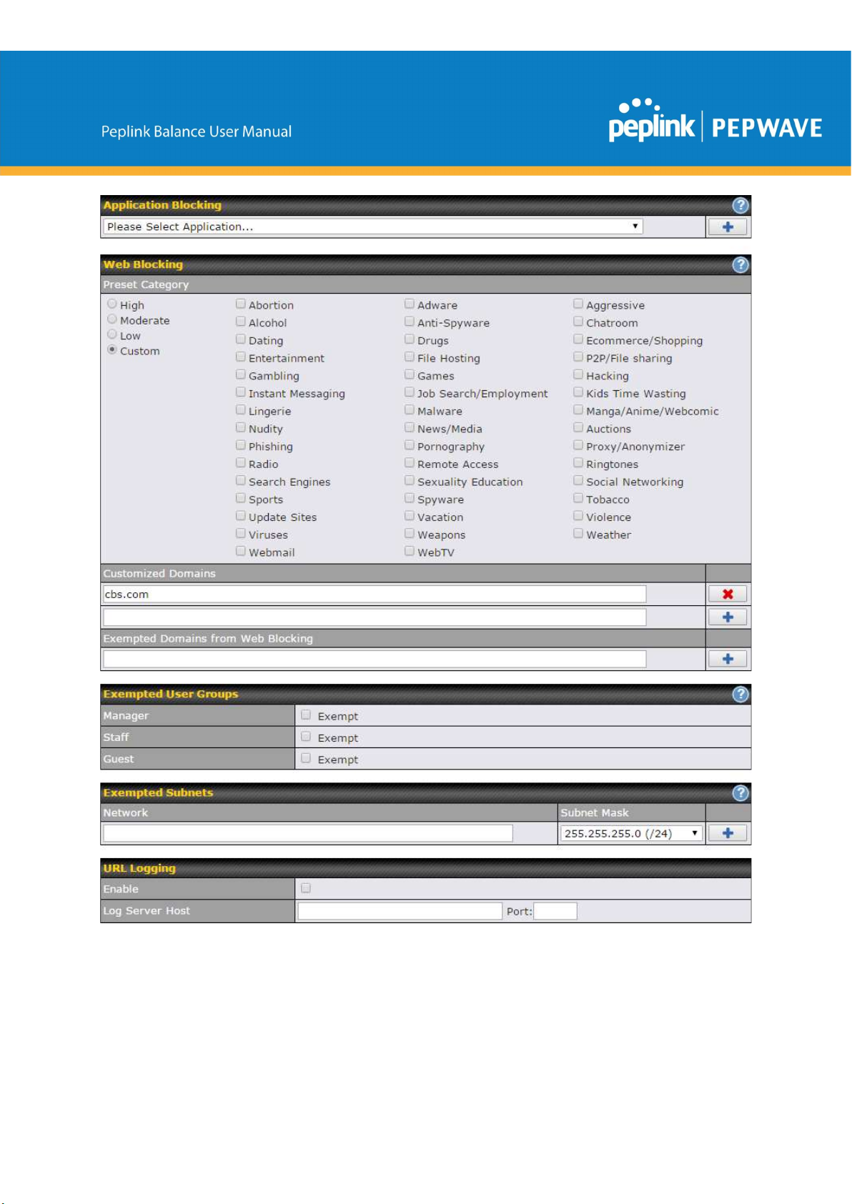
Application Blocking
Choose applications to be blocked from LAN/PPTP/PepVPN peer clients' access, except for
those on the Exempted User Groups or Exempted Subnets defined below.
Web Blocking
Defines web site domain names to be blocked from LAN/PPTP/PepVPN peer clients' access
except for those on the Exempted User Groups or Exempted Subnets defined below.
If "foobar.com" is entered, any web site with a host name ending in foobar.com will be blocked,
e.g. www.foobar.com, foobar.com, etc. However, "myfoobar.com" will not be blocked.
You may enter the wild card ".*" at the end of a domain name to block any web site with a host
name having the domain name in the middle. If you enter "foobar.*", then "www.foobar.com",
"www.foobar.co.jp", or "foobar.co.uk" will be blocked. Placing the wild card in any other position
is not supported.
The device will inspect and look for blocked domain names on all HTTP traffic. Secure web
(HTTPS) traffic is not supported.
Customized Domains
Enter an appropriate website address, and the Peplink Balance will block and disallow
LAN/PPTP/SpeedFusionTM peer clients to access these websites. Exceptions can be added
using the instructions in Sections 21.2.1.4 and 21.2.1.5.
You may enter the wild card ".*" at the end of a domain name to block any web site with a host
name having the domain name in the middle. For example, If you enter "foobar.*," then
"www.foobar.com," "www.foobar.co.jp," or "foobar.co.uk" will be blocked. Placing the wild card
in any other position is not supported.
The Peplink Balance will inspect and look for blocked domain names on all HTTP traffic. Secure
web (HTTPS) traffic is not supported.
Exempted User Groups
Check and select pre-defined user group(s) who can be exempted from the access blocking rules.
User groups can be defined at QoS>User Groups section. Please refer to Section 20.1 for
details.
Exempted Subnets
With the subnet defined in the field, clients on the particular subnet(s) can be exempted from the
https://www.peplink.com 105 Copyright @ 2019 Peplink
access blocking rules.
URL Logging
Click enable, and the enter the ip address and port (if applicable) where your remote syslog
server is located.
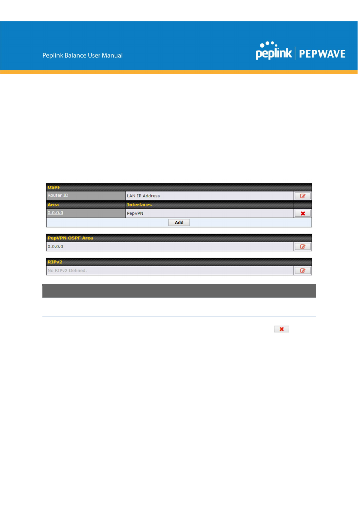
10.13 OSPF & RIPv2
The Peplink Balance supports OSPF and RIPv2 dynamic routing protocols. Click the Network
tab from the top bar, and then click the OSPF & RIPv2 item on the sidebar to reach the following
menu:
OSPF
Router ID
Area
https://www.peplink.com 106 Copyright @ 2019 Peplink
This field determines the ID of the router. By default, this is specified as the LAN IP
address. If you want to specify your own ID, enter it in the Custom field.
This is an overview of the OSPFv2 areas you have defined. Click on the area name to
configure it. To set a new area, click Add. To delete an existing area, click .
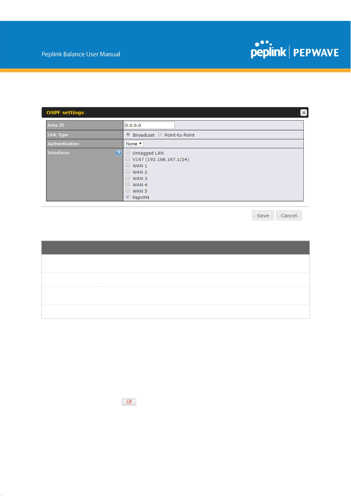
OSPF Settings
Area ID
Link Type
Authentication
Interfaces
To access RIPv2 settings, click .
https://www.peplink.com 107 Copyright @ 2019 Peplink
Determine the name of your Area ID to apply to this group. Machines linked to this group
will send and receive related OSPF packets, while unlinked machines will ignore it.
Choose the network type that this area will use.
Choose an authentication method, if one is used, from this drop-down menu. Available
options are MD5 and Text. Enter the authentication key next to the drop-down menu.
Determine which interfaces this area will use to listen to and deliver OSPF packets

RIPv2 Settings
Authentication
Interfaces
PepVPN Route
Isolation
Network
Advertising
Static Route
Advertising
Choose an authentication method, if one is used, from this drop-down menu. Available
options are MD5 and Text. Enter the authentication key next to the drop-down menu.
Determine which interfaces this group will use to listen to and deliver RIPv2 packets.
OSPF & RIPv2 Route Advertisement
Isolate PepVPN peers from each other. Received PepVPN routes will not be
forwarded to other PepVPN peers to reduce bandwidth consumption.
Networks to be advertised over OSPF & RIPv2. If no network is selected, all
LAN / VLAN networks will be advertised by default.
Enable this option to advertise LAN static routes over OSPF & RIPv2. Static
routes that match the Excluded Networks table will not be advertised.
.
https://www.peplink.com 108 Copyright @ 2019 Peplink
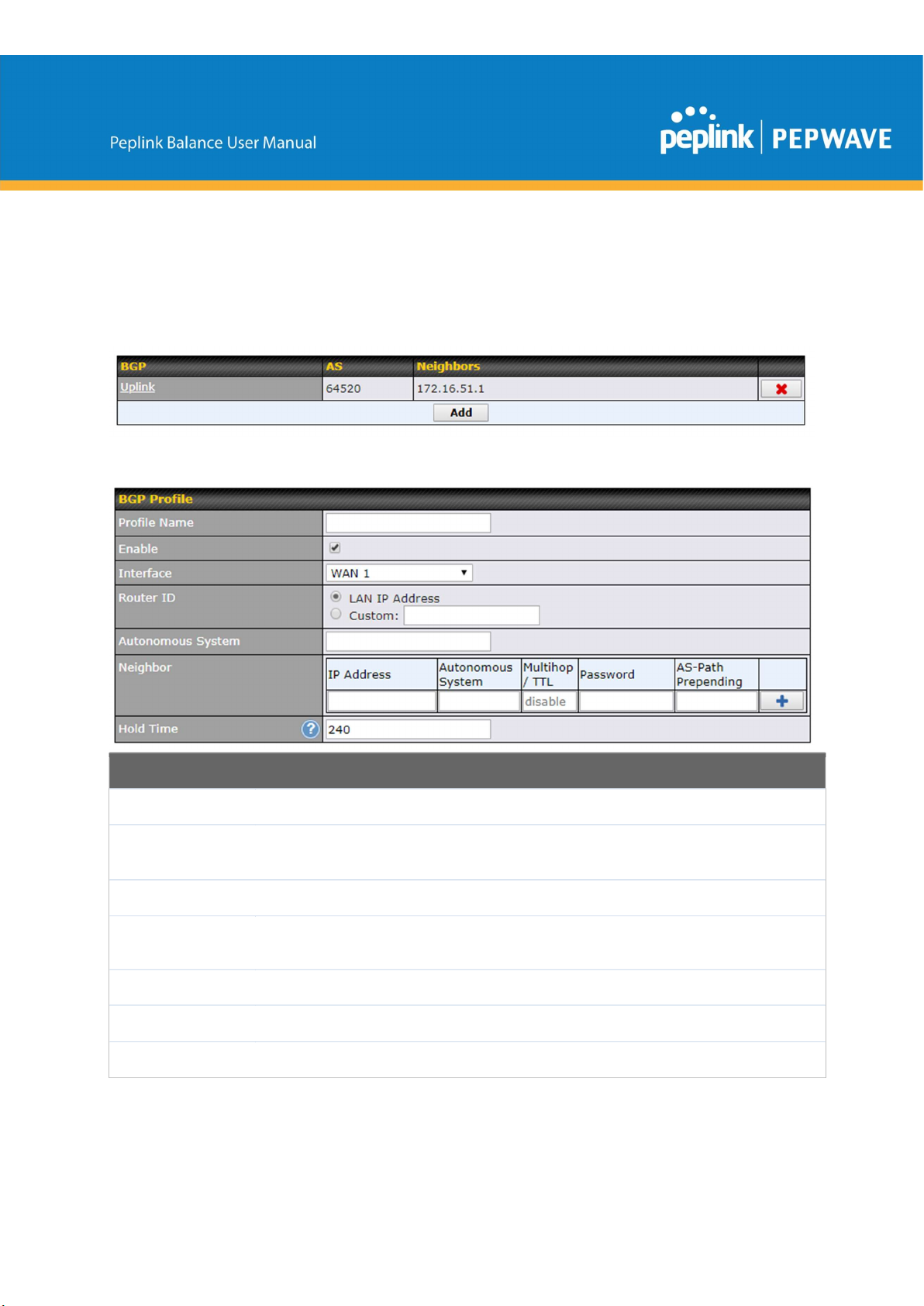
10.14 BGP
Click the Network tab from the top bar, and then click the BGP item on the sidebar to configure
BGP.
Click "x" to delete a BGP profile
Click "Add" to add a new BGP profile
BGP
Name
Enable
Interface
Autonomous
System
Neighbor
IP address
Autonomous
https://www.peplink.com 109 Copyright @ 2019 Peplink
This field is for specifying a name to represent this profile.
When this box is checked, this BGP profile will be enabled.
Otherwise, it will be disabled.
The interface where BGP neighbor is located
The Autonomous System Number (ASN) of this profile
BGP Neighbor's details
Neighbor's IP address
Neighbor's ASN

System
Multihop/TTL
Time-to-live (TTL) of BGP packet.
Leave it blank if BGP neighbor is directly connected, otherwise you must
specify a TTL value. Accurately, this option should be used if the configured
neighbor IP address does not match the selected Interface’s network
subnets. TTL value must be between 2 to 255.
Password
AS-Path
Prepending:
Hold Time
Network
Advertising
Optional password for MD5 authentication of BGP sessions.
AS path to be prepended to the routes received from this neighbor.
The value must be a comma separated ASN.
For example "64530,64531" will prepend "64530, 64531" to received routes.
Time in seconds to wait for a keepalive message from the neighbor before
considering the BGP connection is staled.
This value must be either 0 (infinite hold time) or between 3 and 65535
inclusively.
Networks to be advertised to BGP neighbor.
Static Route
Advertising
Advertise OSPF
Route
https://www.peplink.com 110 Copyright @ 2019 Peplink
Enable this option to advertise LAN static routes. Static routes that match
the Excluded Networks table will not be advertised.
When this box is checked, all learnt OSPF routes will be advertised.
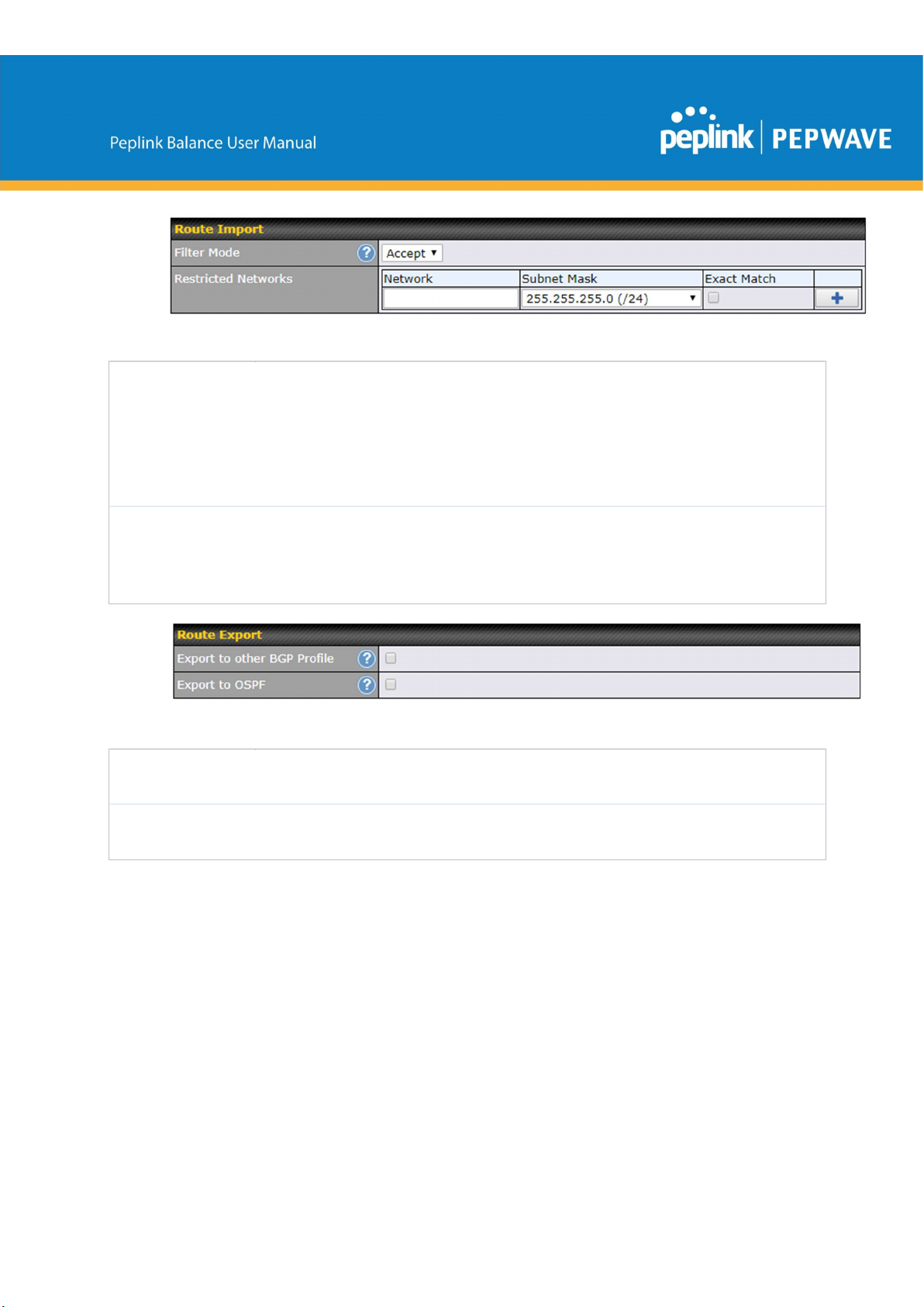
Filter Mode
Restricted
Networks
This option selects the route import filter mode.
None: all BGP routes will be accepted.
Accept: Routes in "Restricted Networks" will be accepted, routes not in the
list will be rejected.
Reject: Routes in "Restricted Networks" will be rejected, routes not in the
list will be accepted.
This specifies the network in the “route import” entry
Exact Match: When this box is checked, only routes with the same
Networks and Subnet Mask will be filtered.
Otherwise, routes within the Networks and Subnet will be filtered.
Export to other
BGP Profile
Export to OSPF
When this box is checked, routes learnt from this BGP profile will export to
other BGP profiles.
When this box is checked, routes learnt from this BGP profile will export to
the OSPF routing protocol.
10.15 Remote User Access
Networks routed by a Peplink Balance can be remotely accessed via L2TP with IPsec or PPTP.
To configure this feature, navigate to Network > Remote User Access
https://www.peplink.com 111 Copyright @ 2019 Peplink

Remote User Access Settings
Enable
VPN Type
Preshared Key
Listen On
User Accounts
https://www.peplink.com 112 Copyright @ 2019 Peplink
Click the checkbox to enable Remote User Access.
Determine whether remote devices can connect to the Balance using L2TP with IPsec or
PPTP. For greater security, we recommend you connect using L2TP with IPsec.
Enter your preshared key in the text field. Please note that remote devices will need this
preshared key to access the Balance.
This setting is for specifying the WAN IP addresses where the PPTP server of the router
should listen on.
This setting allows you to define the PPTP User Accounts. Click Add to input username and
password to create an account. After adding the user accounts, you can click on a
username to edit the account password. Click the button X to delete the account in its
corresponding row.

Click the button to switch to enters user accounts by pasting the information in.CSV
format.
10.16 Misc. Settings
10.16.1 High Availability
The Peplink Balance supports high availability (HA) configurations via an open standard virtual
router redundancy protocol (VRRP, RFC 3768).
In an HA configuration, two same-model Peplink Balance units provide redundancy and failover
in a master-slave arrangement. In the event that the master unit is down, the slave unit
becomes active.
High availability will be disabled automatically where there is a drop-in connection configured on
a LAN bypass port.
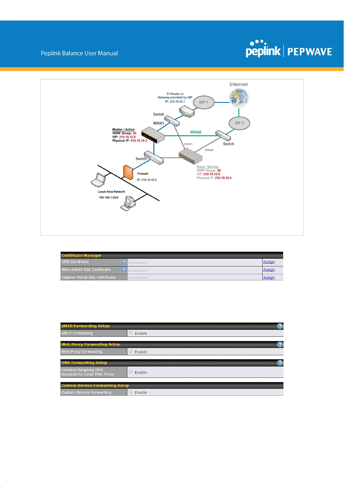
The following diagram illustrates an HA configuration with two Peplink Balance units and two
Internet connections:
In the diagram, the WAN ports of each Peplink Balance unit connect to the router and to the
modem. Both Peplink Balance units connect to the same LAN switch via a LAN port.
An elaboration on the technical details of the implementation of virtual router redundancy
protocol (VRRP, RFC 3768) by the Balance follows:
● In an HA configuration, the two Peplink Balance units communicate with each other
using VRRP over the LAN.
● The two Peplink Balance units broadcast heartbeat signals to the LAN at a frequency of
one heartbeat signal per second.
https://www.peplink.com 113 Copyright @ 2019 Peplink

● In the event that no heartbeat signal from the master Peplink Balance unit is received in
3 seconds (or longer) since the last heartbeat signal, the slave Peplink Balance unit
becomes active.
● The slave Peplink Balance unit initiates the WAN connections and binds to a previously
configured LAN IP address.
● At a subsequent point when the master Peplink Balance unit recovers, it will once again
become active.
You can configure high availability at Network>Misc. Settings>High Availability.
Interface for Master Router Interface for Slave Router
High Availability
Enable
Group Number
Preferred Role
Checking this box specifies that the Peplink Balance unit is part of a high availability
configuration.
This number identifies a pair of Peplink Balance units operating in a high availability
configuration. The two Peplink Balance units in the pair must have the same Group Number
value.
This setting specifies whether the Peplink Balance unit operates in master or slave mode.
Click the corresponding radio button to set the role of the unit. One of the units in the pair
must be configured as the master, and the other unit must be configured as the slave.
Resume
Master Role
Upon
This option is displayed when Master mode is selected in Preferred Role. If this option is
enabled, once the device has recovered from an outage, it will take over and resume its
Master role from the slave unit.
Recovery
This option is displayed when Slave mode is selected in Preferred Role. If this option is
Configuration
Sync.
Master Serial
Number
https://www.peplink.com 114 Copyright @ 2019 Peplink
enabled and the Master Serial Number entered matches with the actual master unit's, the
master unit will automatically transfer the configuration to this unit. Please make sure
the LAN IP Address and the Subnet Mask fields are set correctly in the LAN settings page.
You can refer to the Event Log for the configuration synchronization status.
If Configuration Sync. is checked, the serial number of the master unit is required here for
the feature to work properly.

Administration
Virtual IP
LAN
The HA pair must share the same Virtual IP. The Virtual IP and the LAN Administration IP
must be under the same network.
This setting specifies a LAN IP address to be used for accessing administration functionality.
This address should be unique within the LAN.
IP
Subnet Mask
This setting specifies the subnet mask of the LAN.
Important Note
For Balance routers in NAT mode, the virtual IP (VIP) should be set as the default gateway for all hosts sitting on
the LAN segment. For example, a firewall sitting behind the Balance should set its default gateway as the virtual IP
instead of the IP of the master Balance.
In drop-in mode, no other configuration needs to be set.
https://www.peplink.com 115 Copyright @ 2019 Peplink
Please note that the drop-in WAN cannot be configured as a LAN bypass port while it is configured for high
availability.
10.16.2 Certificate Manager
This section allows you to assign certificates for local VPN and web admin SSL. The local keys
will not be transferred to another device by any means.
10.16.3 Service Forwarding
Service forwarding settings are located at Network>Misc. Settings>Service Forwarding.
https://www.peplink.com 116 Copyright @ 2019 Peplink

SMTP Forwarding
Web Proxy
Forwarding
DNS Forwarding
Service Forwarding
When this option is enabled, all outgoing SMTP connections destined for any host at
TCP port 25 will be intercepted. These connections will be redirected to a specified
SMTP server and port number. SMTP server settings for each WAN can be specified
after selecting Enable.
When this option is enabled, all outgoing connections destined for the proxy server
specified in Web Proxy Interception Settings will be intercepted. These
connections will be redirected to a specified web proxy server and port number. Web
proxy interception settings and proxy server settings for each WAN can be specified
after selecting Enable.
When this option is enabled, all outgoing DNS lookups will be intercepted and
redirected to the built-in DNS name server. If any LAN device is using the DNS name
servers of a WAN connection, you may want to enable this option to enhance the
DNS availability without modifying the DNS server setting of the clients. The built-in
DNS name server will distribute DNS lookups to corresponding DNS servers of all
available WAN connections. In this case, DNS service will not be interrupted, even if
any WAN connection is down.
Custom Service
Forwarding
When custom service forwarding is enabled, outgoing traffic with the specified TCP
port will be forwarded to a local or remote server by defining its IP address and port
number.
https://www.peplink.com 117 Copyright @ 2019 Peplink
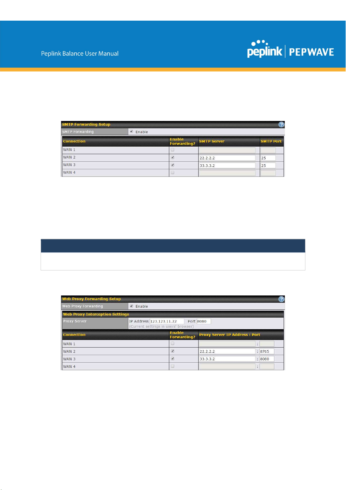
SMTP Forwarding
Some ISPs require their users to send e-mails via the ISP’s SMTP server. All outgoing SMTP
connections are blocked except those connecting to the ISP’s. The Peplink Balance supports
the interception and redirection of all outgoing SMTP connections (destined for TCP port 25) via
a WAN connection to the WAN’s corresponding SMTP server.
To enable the feature, select Enable under SMTP Forwarding Setup. Check Enable
Forwarding for the WAN connection(s) that needs forwarding. Under SMTP Server, enter the
ISP’s e-mail server host name or IP address. Under SMTP Port, enter the TCP port number for
each WAN.
The Peplink Balance will intercept SMTP connections. Choose a WAN port according to the
outbound policy, and then forward the connection to the SMTP server, if the chosen WAN has
enabled forwarding. If the forwarding is disabled for a WAN connection, SMTP connections for
the WAN will be simply be forwarded to the connection’s original destination.
Note
If you want to route all SMTP connections only to particular WAN connection(s), you should create a custom rule
in outbound policy (see Section 16.1).
Web Proxy Forwarding
When this feature is enabled, the Peplink Balance will intercept all outgoing connections
destined for the proxy server specified in Web Proxy Server Interception Settings. Then it will
choose a WAN connection according to the outbound policy and forward the connection to the
specified web proxy server and port number. Redirected server settings for each WAN can be
https://www.peplink.com 118 Copyright @ 2019 Peplink

set here. If forwarding is disabled for a WAN, then web proxy connections for that WAN will
simply be forwarded to the connection’s original destination.
DNS Forwarding
When DNS forwarding is enabled, all clients’ outgoing DNS requests will also be intercepted
and forwarded to the built-in DNS proxy server.
Custom Service Forwarding
After clicking the enable checkbox, enter your TCP port for traffic heading to the router, and then
specify the IP Address and Port of the server you wish to forward to the service to.
10.16.4 Service Passthrough
Service passthrough settings can be found at Network>Misc. Settings>Service Passthrough.
Some Internet services need to be specially handled in a multi-WAN environment. The Peplink
Balance can handle these services such that Internet applications do not notice it is behind a
multi-WAN router. Settings for service passthrough support are available here.
Service Passthrough Support
https://www.peplink.com 119 Copyright @ 2019 Peplink

Session initiation protocol, aka SIP, is a voice-over-IP protocol. The Peplink Balance can
act as a SIP application layer gateway (ALG) which binds connections for the same SIP
session to the same WAN connection and translate IP address in the SIP packets
SIP
correctly in NAT mode. Such passthrough support is always enabled and there are two
modes for selection: Standard Mode and Compatibility Mode.
If your SIP server’s signal port number is non-standard, you can check the box Define
custom signal ports and input the port numbers to the text boxes.
H.323
FTP
TFTP
IPsec NAT-T
11 AP Tab
11.1 AP
With this option enabled, protocols that provide audio-visual communication sessions will
be defined on any packet network and passthrough the Balance.
FTP sessions consist of two TCP connections; one for control and one for data. In a
multi-WAN situation, they must be routed to the same WAN connection. Otherwise,
problems will arise in transferring files. By default, the Peplink Balance monitors TCP
control connections on port 21 for any FTP connections and binds TCP connections of
the same FTP session to the same WAN.
If you have an FTP server listening on a port number other than 21, you can check
Define custom control ports and enter the port numbers in the text boxes.
The Peplink Balance monitors outgoing TFTP connections and routes any incoming
TFTP data packets back to the client. Select Enable if you want to enable TFTP
passthrough support.
This field is for enabling the support of IPsec NAT-T passthrough. UDP ports 500, 4500,
and 10000 are monitored by default.
You may add more custom data ports that your IPsec system uses by checking Define
custom ports. If the VPN contains IPsec site-to-site VPN traffic, check Route IPsec
Site-to-Site VPN and choose the WAN connection to route the traffic to.
11.1.1 AP Controller
Clicking on the AP tab will default to this menu, where you can view basic AP management
options:
https://www.peplink.com 120 Copyright @ 2019 Peplink
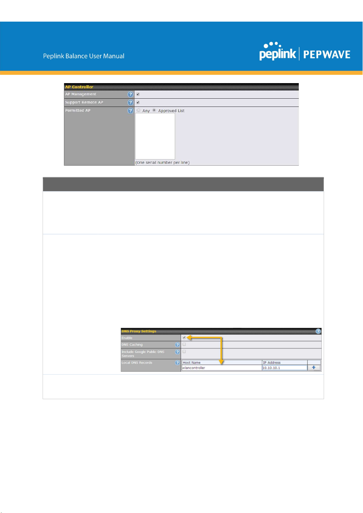
AP
Management
Support
Remote AP
AP Controller
The AP controller for managing Pepwave APs can be enabled by checking this box. When
this option is enabled, the AP controller will wait for management connections originating
from APs over the LAN on TCP and UDP port 11753. It will also wait for captive portal
connections on TCP port 443. An extended DHCP option, CAPWAP Access Controller
addresses (field 138), will be added to the DHCP server. A local DNS record, AP
Controller, will be added to the local DNS proxy.
The AP controller supports remote management of Pepwave APs. When this option is
enabled, the AP controller will wait for management connections originating from remote
APs over the WAN on TCP and UDP port 11753. It will also wait for captive portal
connections on TCP port 443.
The DHCP server and/or local DNS server of the remote AP’s network should be
configured in the DNS Proxy Settings menu under Network>LAN. The procedure is as
follows:
1.
Define an extended DHCP option, CAPWAP Access Controller addresses (field
138), in the DHCP server, where the values are the AP controller's public IP
addresses; and/or
2.
Create a local DNS record for the AP controller with a value corresponding to the AP
controller's public IP address.
Access points to manage can be specified here. If Any is selected, the AP controller will
Permitted AP
manage any AP that reports to it. If Approved List is selected, only APs with serial
numbers listed in the provided text box will be managed.
11.1.2 Wireless SSID
Wireless network settings, including the name of the network (SSID) and security policy, can be
https://www.peplink.com 121 Copyright @ 2019 Peplink
defined and managed in this section. After defining a wireless network, users can choose the
network in AP Profiles.
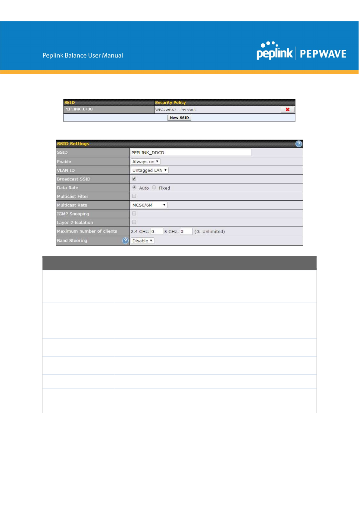
Click the button New SSID to create a new network profile, or click the existing network profile
to modify its settings.
SSID Settings
SSID
Enable
VLAN ID
Broadcast SSID
Data Rate A
Multicast FilterA
Multicast RateA
https://www.peplink.com 122 Copyright @ 2019 Peplink
This setting specifies the SSID of the virtual AP to be scanned by Wi-Fi clients.
Choose an operating schedule for this SSID. Define schedules under System >
Schedule
This setting specifies the VLAN ID to be tagged on all outgoing packets
generated from this wireless network (i.e., packets that travel from the Wi-Fi
segment through the Pepwave AP One unit to the Ethernet segment via the LAN
port). The default value of this setting is 0, which means VLAN tagging is
disabled (instead of tagged with zero).
This setting specifies whether or not Wi-Fi clients can scan the SSID of this
wireless network. Broadcast SSID is enabled by default.
Select Auto to allow the Peplink Balance to set the data rate automatically, or
select Fixed and choose a rate from the displayed drop-down menu.
This setting enables the filtering of multicast network traffic to the wireless SSID.
This setting specifies the transmit rate to be used for sending multicast network
traffic. The selected Protocol and Channel Bonding settings will affect the rate
options and values available here.
None
Deny all except listed
Accept all except listed
RADIUS MAC
IGMP Snooping A
DHCP Option 82 A
Network Priority
(QoS) A
Layer 2 Isolation A
Maximum Number
of Clients
Band Steering A
A
- Advanced feature. Click the button on the top right-hand corner to activate.
To allow the Peplink Balance to listen to internet group management protocol
(IGMP) network traffic, select this option.
If you use a distributed DHCP server/relay environment, you can enable this
option to provide additional information on the manner in which clients are
physically connected to the network.
Select from Gold, Silver, and Bronze to control the QoS priority of this wireless
network’s traffic.
Layer 2 refers to the second layer in the ISO Open System Interconnect model.
When this option is enabled, clients on the same VLAN, SSID, or subnet are
isolated to that VLAN, SSID, or subnet, which can enhance security. Traffic is
passed to upper communication layer(s). By default, the setting is disabled.
Enter the maximum number of clients on the 2.4Ghz channel and on the 5Ghz
channel.
Band steering allows the Peplink Balance to steer AP clients from the 2.4 GHz
band to the 5GHz band for better usage of bandwidth. To make steering
mandatory, select Enforce. To cause the Peplink Balance to preferentially
choose steering, select Prefer. The default for this setting is Disable.
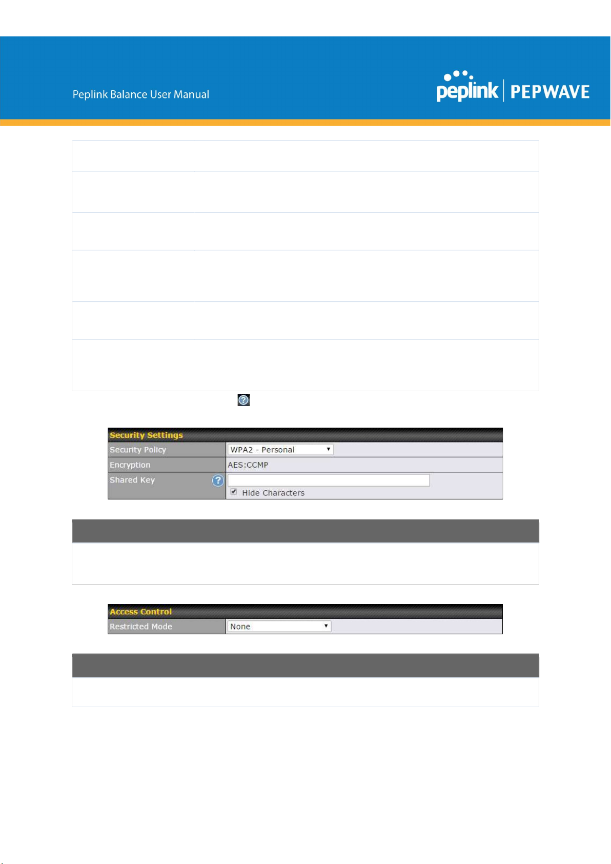
Security Settings
Security
Policy
This setting configures the wireless authentication and encryption methods. Available
options are Open (No Encryption), WPA/WPA2 - Personal, WPA/WPA2 – Enterprise
and Static WEP.
Access Control
Restricted
https://www.peplink.com 123 Copyright @ 2019 Peplink
The settings allow administrator to control access using Mac address filtering. Available
options are
,
,
, and
Authentication
Mode
Authentication.
When WPA/WPA2 - Enterprise is configured, RADIUS-based 802.1 x authentication is
enabled. Under this configuration, the Shared Key option should be disabled. When using
this method, select the appropriate version using the V1/V2 controls. The security level of this
method is known to be very high.
When WPA/WPA2- Personal is configured, a shared key is used for data encryption and
authentication. When using this configuration, the Shared Key option should be enabled. Key
length must be between eight and 63 characters (inclusive). The security level of this method
is known to be high.
The configuration of Static WEP parameters enables pre-shared WEP key encryption.
Authentication is not supported by this method. The security level of this method is known to
be weak.
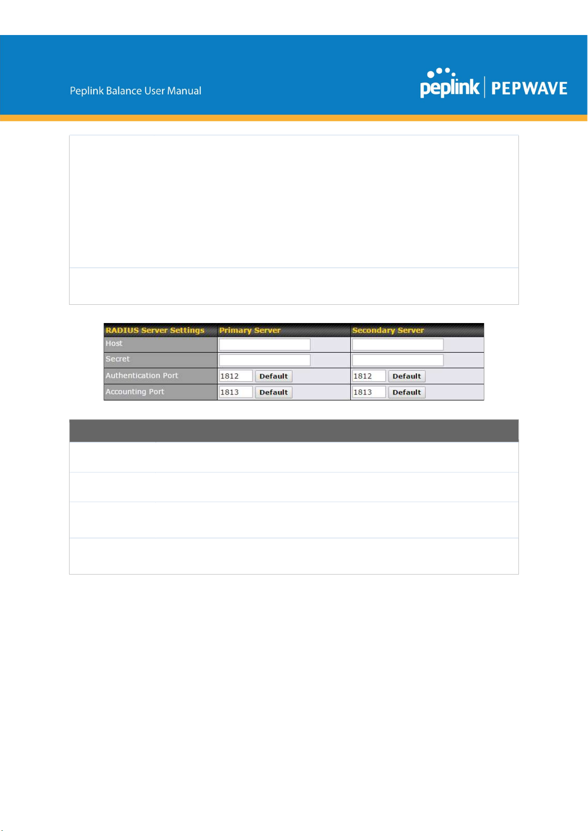
MAC Address
List
Host
Secret
Port
Accounting
Port
Connection coming from the MAC addresses in this list will be either denied or accepted
based the option selected in the previous field.
RADIUS Server Settings
Enter the IP address of the primary RADIUS server and, if applicable, the secondary RADIUS
server.
Enter the RADIUS shared secret for the primary server and, if applicable, the secondary
RADIUS server.
In field, enter the UDP authentication port(s) used by your RADIUS server(s) or click the
Default button to enter 1812.
In field, enter the UDP accounting port(s) used by your RADIUS server(s) or click the Default
button to enter 1813.
https://www.peplink.com 124 Copyright @ 2019 Peplink
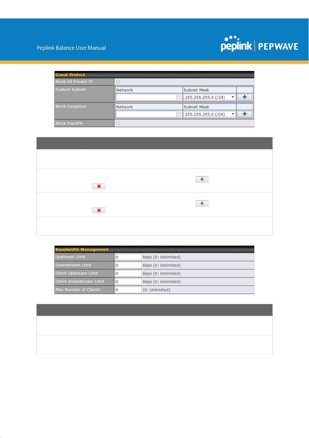
Guest Protect
Block All
Private IP
Custom
Subnet
Block
Exception
Block
PepVPN
Check this box to deny all connection attempts by private IP addresses.
To create a custom subnet for guest access, enter the IP address and choose a subnet mask
from the drop-down menu. To add the new subnet, click . To delete a custom subnet,
click .
To block access from a particular subnet, enter the IP address and choose a subnet mask
from the drop-down menu. To add the new subnet, click . To delete a blocked subnet,
click .
To block PepVPN access, check this box.
Bandwidth Management
Upstream
Limit
Downstream
Limit
https://www.peplink.com 125 Copyright @ 2019 Peplink
Enter a value in kpbs to limit the wireless network’s upstream bandwidth. Enter 0 to allow
unlimited upstream bandwidth.
Enter a value in kpbs to limit the wireless network’s downstream bandwidth. Enter 0 to allow
unlimited downstream bandwidth.

Port
Any Port
Client
Upstream
Limit
Client
Downstream
Limit
Max Number
of Clients
Firewall Mode
Enter a value in kpbs to limit connected clients’ upstream bandwidth. Enter 0 to allow
unlimited upstream bandwidth.
Enter a value in kpbs to limit connected clients’ downstream bandwidth. Enter 0 to allow
unlimited downstream bandwidth.
Enter the maximum number of clients that can simultaneously connect to the wireless network
or enter 0 to allow an unlimited number of connections.
Firewall Settings
Choose Flexible – Allow all except… or Lockdown – Block all except… to turn on the
firewall. Once you save changes, the . Button will appear for you to create rules
for the firewall exceptions. See the discussion below for details on creating a firewall rule. To
delete a rule, click the associated button. To turn off the firewall, select Disable.
Firewall Rule
Name
Type
Protocol /
https://www.peplink.com 126 Copyright @ 2019 Peplink
Enter a descriptive name for the firewall rule in this field.
Choose Port, Domain, IP Address, or MAC Address to allow or deny traffic from any of
those identifiers. Depending on the option chosen, the following fields will vary.
Choose TCP or UDP from the Protocol drop-down menu to allow or deny traffic using either
of those protocols. From the
drop-down menu, choose
to allow or deny TCP or

Port
UDP traffic on any port. Choose Single Port and then enter a port number in the provided
field to allow or block TCP or UDP traffic from that port only. You can also choose Port
Range and enter a range of ports in the provided fields to allow or deny TCP or UDP traffic
from the specified port range.
IP Address /
Subnet Mask
MAC Address
11.1.3 Settings
SSID
Operating
Country
If you have chosen IP Address as your firewall rule type, enter the IP address and subnet
mask identifying the subnet to allow or deny.
If you have chosen MAC Address as your firewall rule type, enter the MAC address
identifying the machine to allow or deny.
AP Settings
You can select the wireless networks for 2.4 GHz or 5 GHz seperately for each SSID.
This drop-down menu specifies the national/regional regulations which the Wi-Fi radio
should follow.
● If a North American region is selected, RF channels 1 to 11 will be available
and the maximum transmission power will be 26 dBm (400 mW).
● If European region is selected, RF channels 1 to 13 will be available. The
maximum transmission power will be 20 dBm (100 mW).
NOTE: Users are required to choose an option suitable to local laws and regulations.
Preferred
Frequency
Indicate the preferred frequency to use for clients to connect.
Important Note
Per FCC regulation, the country selection is not available on all models marketed in
the US. All US models are fixed to US channels only.
https://www.peplink.com 127 Copyright @ 2019 Peplink

Protocol
AP Settings (part 2)
This option allows you to specify whether 802.11b and/or 802.11g client association
requests will be accepted. Available options are 802.11ng and 802.11na. By default,
802.11ng is selected.
Channel Width
Channel
Auto Channel
Update
Output Power
Available options are 20 MHz, 40 MHz, and Auto (20/40 MHz) . Default is Auto (20/40
MHz), which allows both widths to be used simultaneously.
This option allows you to select which 802.11 RF channel will be utilized. Channel 1
(2.412 GHz) is selected by default.
Indicate the time of day at which update automatic channel selection.
This option is for specifying the transmission output power for the Wi-Fi AP. There are
4 relative power levels available – Max, High, Mid, and Low. The actual output power
will be bound by the regulatory limits of the selected country.
Client Signal
Strength
This setting determines the maximum strength at which the Wi-Fi AP can broadcast
Threshold
Maximum
number of
This setting determines the maximum number of clients that can connect to this Wi-Fi
frequency.
clients
Advanced Wi-Fi AP settings can be displayed by clicking the on the top right-hand
corner of the Wi-Fi AP Settings section, which can be found at AP>Settings. Other
models will display a separate section called Wi-Fi AP Advanced Settings, which can
be found at Advanced>Wi-Fi Settings.
https://www.peplink.com 128 Copyright @ 2019 Peplink

Management
VLAN ID
Advanced AP Settings
This field specifies the VLAN ID to tag to management traffic, such as communication
traffic between the AP and the AP Controller. The value is zero by default, which means
that no VLAN tagging will be applied.
NOTE: Change this value with caution as alterations may result in loss of connection to
the AP Controller.
Operating
Schedule
Beacon Rate A
Beacon Interval
DTIM A
RTS Threshold
Fragmentation
Threshold A
Distance / Time
Convertor
Choose from the schedules that you have defined in System>Schedule. Select the
schedule for the integrated AP to follow from the drop-down menu.
This option is for setting the transmit bit rate for sending a beacon. By default, 1Mbps is
selected.
This option is for setting the time interval between each beacon. By default, 100ms is
A
selected.
This field allows you to set the frequency for the beacon to include delivery traffic
indication messages. The interval is measured in milliseconds. The default value is set to
1 ms.
The RTS (Request to Clear) threshold determines the level of connection required before
A
the AP starts sending data. The recommended standard of the RTS threshold is around
500.
This setting determines the maximum size of a packet before it gets fragmented into
multiple pieces.
Select the range you wish to cover with your Wi-Fi, and the router will make
recommendations for the Slot Time and ACK Timeout.
https://www.peplink.com 129 Copyright @ 2019 Peplink

Slot Time A
ACK Timeout A
Frame
Aggregation A
A
- Advanced feature, please click the button on the top right-hand corner to activate.
This field is for specifying the unit wait time before transmitting a packet. By default, this
field is set to 9 µs.
This field is for setting the wait time to receive an acknowledgement packet before
performing a retransmission. By default, this field is set to 48 µs.
This option allows you to enable frame aggregation to increase transmission throughput.
https://www.peplink.com 130 Copyright @ 2019 Peplink

Web Administration Settings
Enable
Web Access
Protocol
Management
Port
Admin
Username
Admin
Password
Ticking this box enables web admin access for APs located on the WAN.
Determines whether the web admin portal can be accessed thorugh HTTP or HTTPS
Determines the port at which the management UI can be accessed.
Determines the username to be used for logging into the web admin portal
Determines the password for the web admin portal on external AP.
11.2 AP Controller Status
11.2.1 Info
A comprehensive overview of your AP can be accessed by navigating to AP > Info.
https://www.peplink.com 131 Copyright @ 2019 Peplink
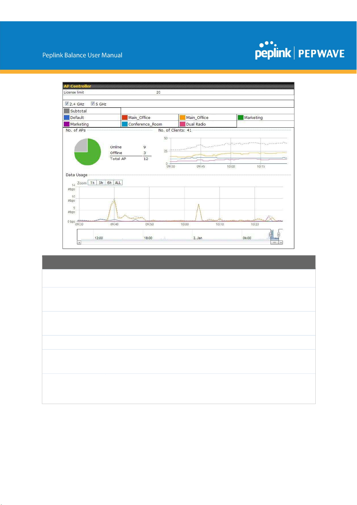
AP Controller
License Limit
Frequency
SSID
No. of APs
No.of Clients
Data Usage
https://www.peplink.com 132 Copyright @ 2019 Peplink
This field displays the maximum number of AP your Balance router can control. You can
purchase licenses to increase the number of AP you can manage.
Underneath, there are two check boxes labeled 2.4 Ghz and 5 Ghz. Clicking either box
will toggle the display of information for that frequency. By default, the graphs display the
number of clients and data usage for both 2.4GHz and 5 GHz frequencies.
The colored boxes indicate the SSID to display information for. Clicking any colored box
will toggle the display of information for that SSID. By default, all the graphs show
information for all SSIDs.
This pie chart and table indicates how many APs are online and how many are offline.
This graph displays the number of clients connected to each network at any given time.
Mouse over any line on the graph to see how many clients connected to a specific SSID
for that point in time.
This graph enables you to see the data usage of any SSID for any given time period.
Mouse over any line on the graph to see the data usage by each SSID for that point in
time. Use the buttons next to Zoom to select the time scale you wish to view. In addition,
you could use the sliders at the bottom to further refine your timescale.
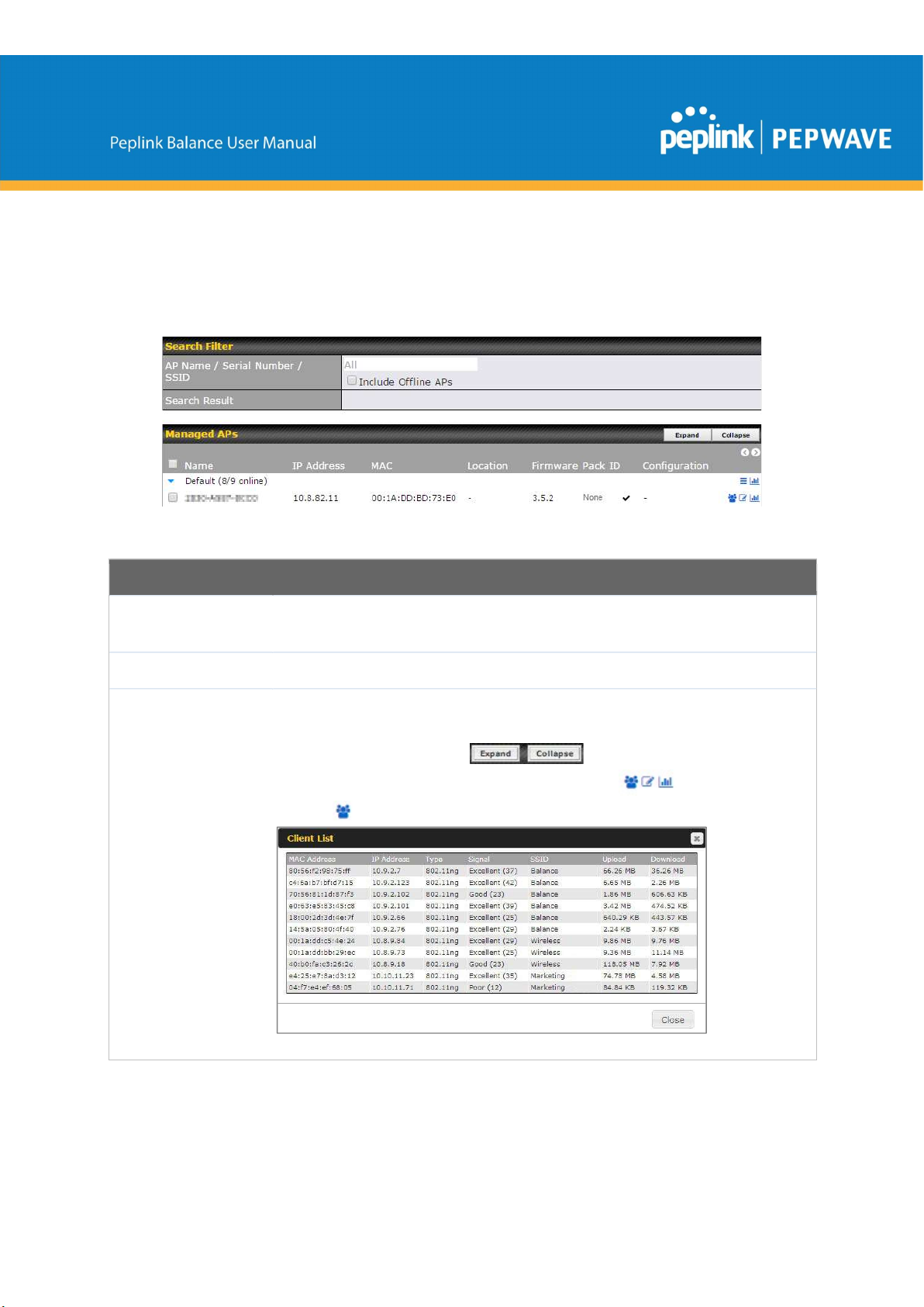
11.2.2 Access Points (Usage)
A detailed breakdown of data usage for each AP is available at AP> Access Point.
Usage
AP Name/Serial
Number
Online Status
Managed
Wireless Devices
This field enables you to quickly find your device if you know its name or serial number.
Fill in the field to begin searching. Partial names and serial numbers are supported.
This button toggles whether your search will include offline devices.
This table shows the detailed information on each AP, including channel, number of
clients, upload traffic, and download traffic. Click the blue arrows at the left of the table to
expand and collapse information on each device group. You could also expand and
collapse all groups by using the buttons.
On the right of the table, you will see the following icons: .
Click the icon to see a usage table for each client:
https://www.peplink.com 133 Copyright @ 2019 Peplink
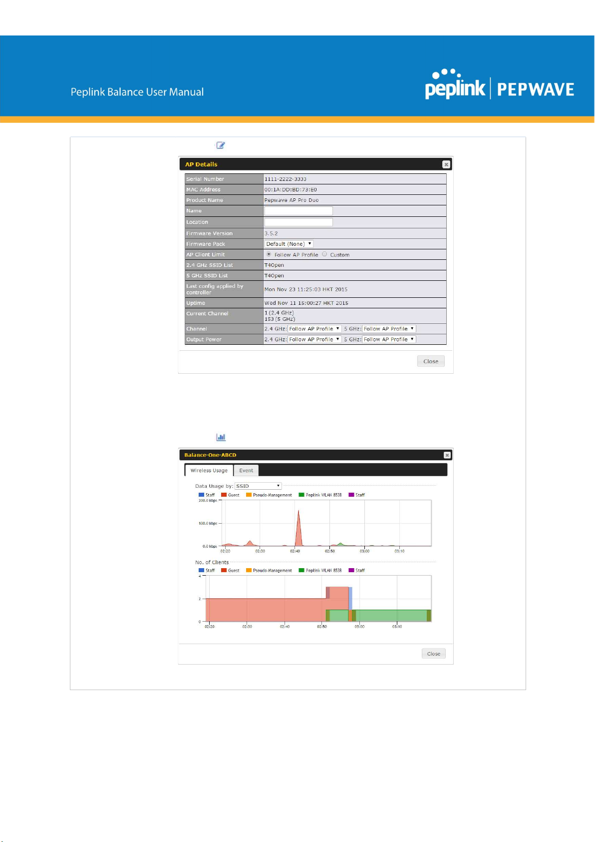
device, using that SSID, at that point in time. On the
Data Usage by
menu, you can
Click the icon to configure each client
For easier network management, you can give each client a name and designate its
location. You can also designate which firmware pack (if any) this client will follow, as
well as the channels on which the client will broadcast.
Click the icon to see a graph displaying usage:
Click any point in the graphs to display detailed usage and client information for that
https://www.peplink.com 134 Copyright @ 2019 Peplink
display the information by SSID or by AP send/receive rate.
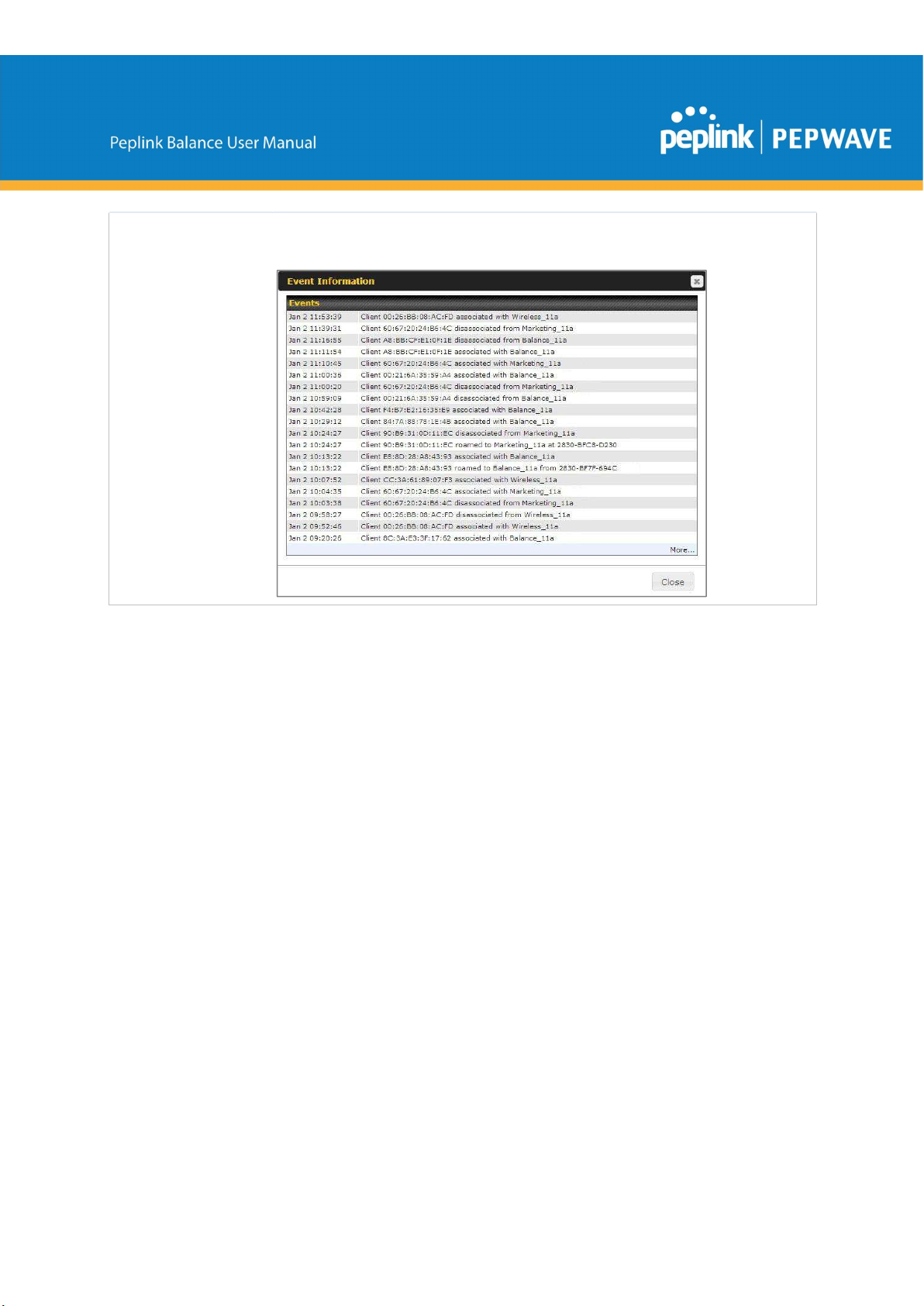
Click the Event tab next to Wireless Usage to view a detailed event log for that
particular device:
11.2.3 Wireless SSID
In-depth SSID reports are available under AP > SSID.
https://www.peplink.com 135 Copyright @ 2019 Peplink
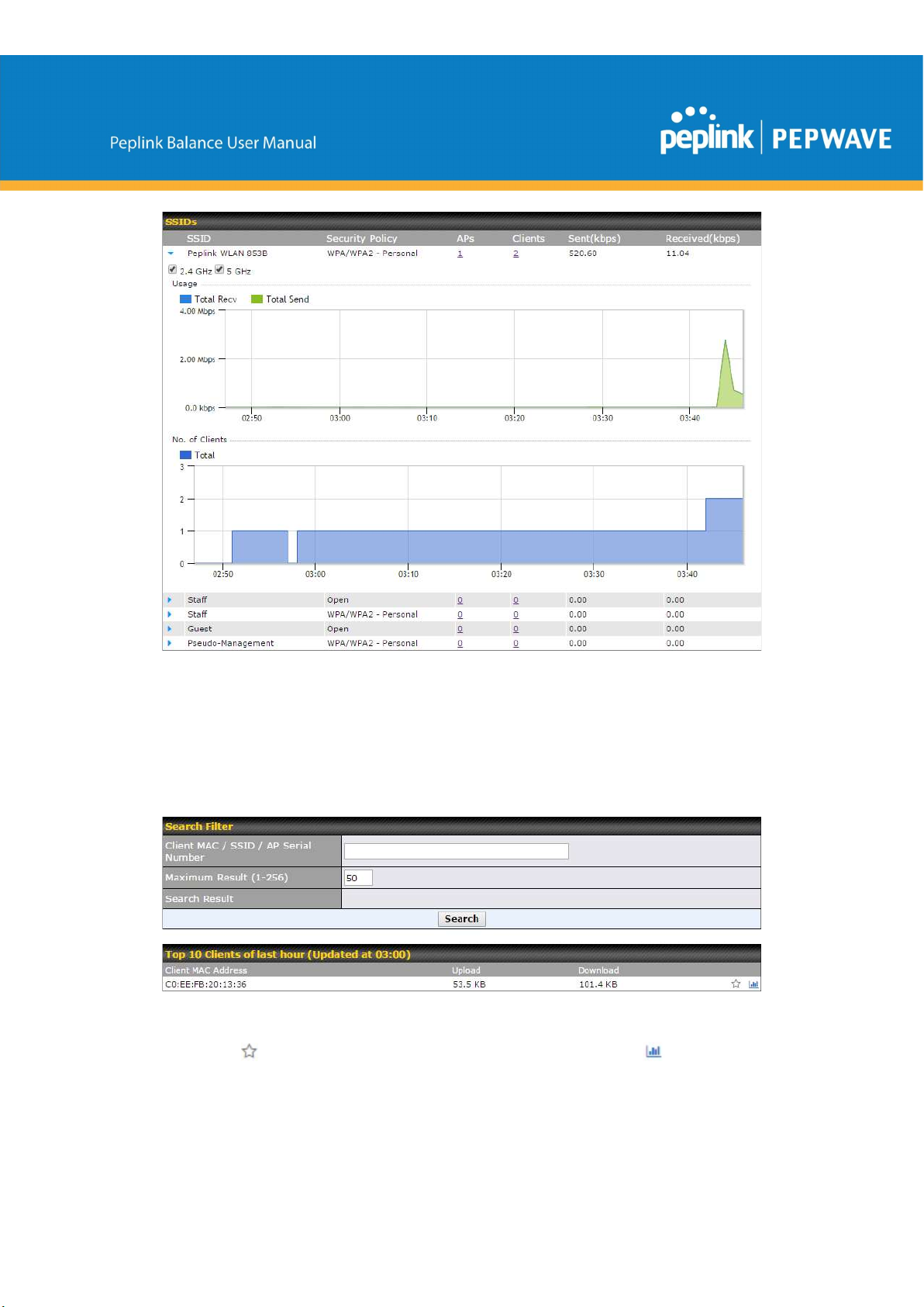
Click the blue arrow on any SSID to obtain more detailed usage information on each
SSID.
11.2.4 Wireless Client
You can search for specific Wi-Fi users by navigating to AP > Wireless Client.
Here, you will be able to see your network’s heaviest users as well as search for specific
users. Click the icon to bookmark specific users, and click the icon for additional
https://www.peplink.com 136 Copyright @ 2019 Peplink
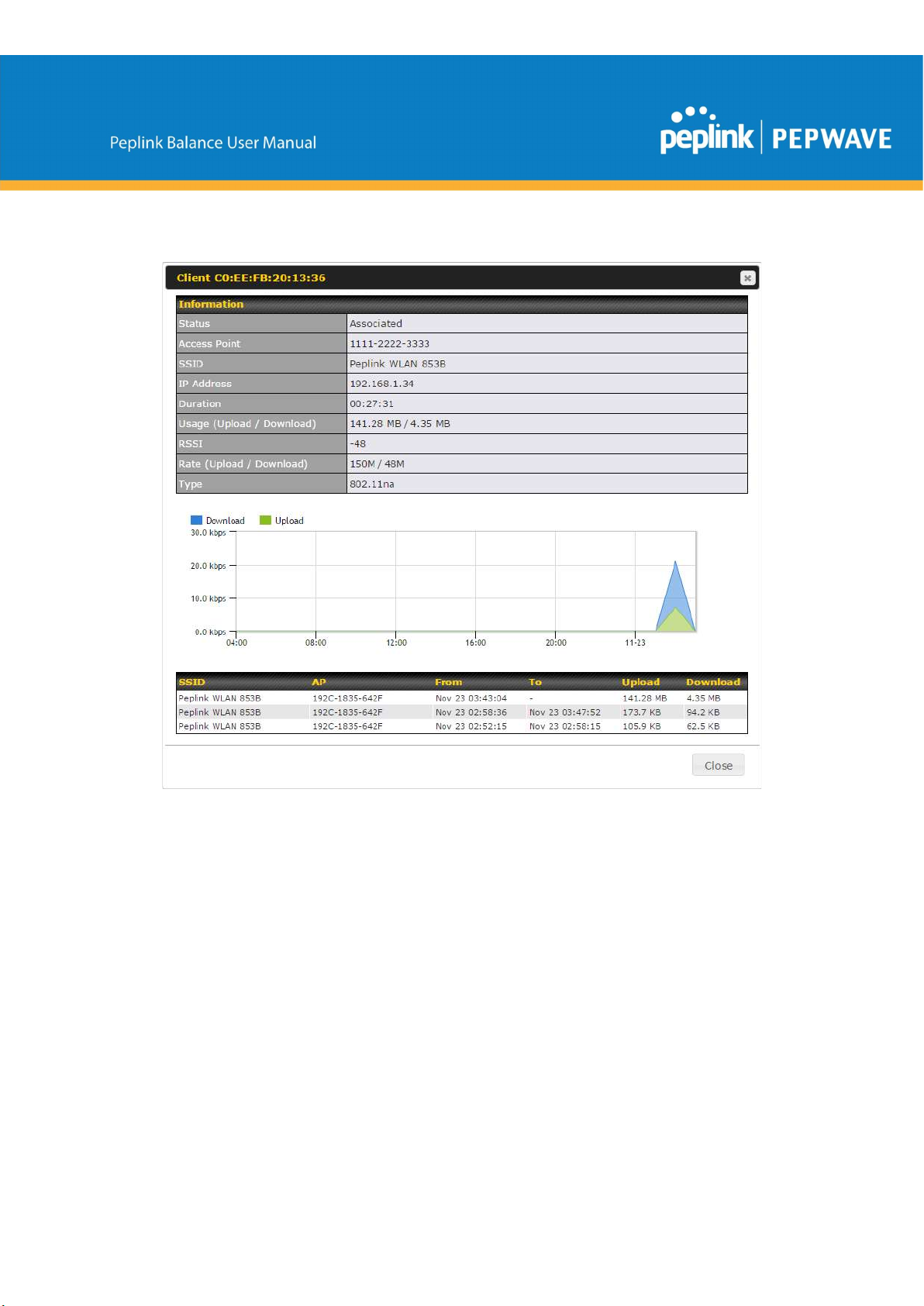
details about each user:
11.2.5 Nearby Device
A listing of near devices can be accessed by navigating to AP > Controller Status >
Nearby Device.
https://www.peplink.com 137 Copyright @ 2019 Peplink

Nearby Devices
Hovering over the device MAC address will result in a popup with information on how this device was detected. Click
the icons and the device will be moved to the bottom table of identified devices.
11.2.6 Event Log
You can access the AP Controller Event log by navigating to AP > Controller Status >
Event Log.
https://www.peplink.com 138 Copyright @ 2019 Peplink
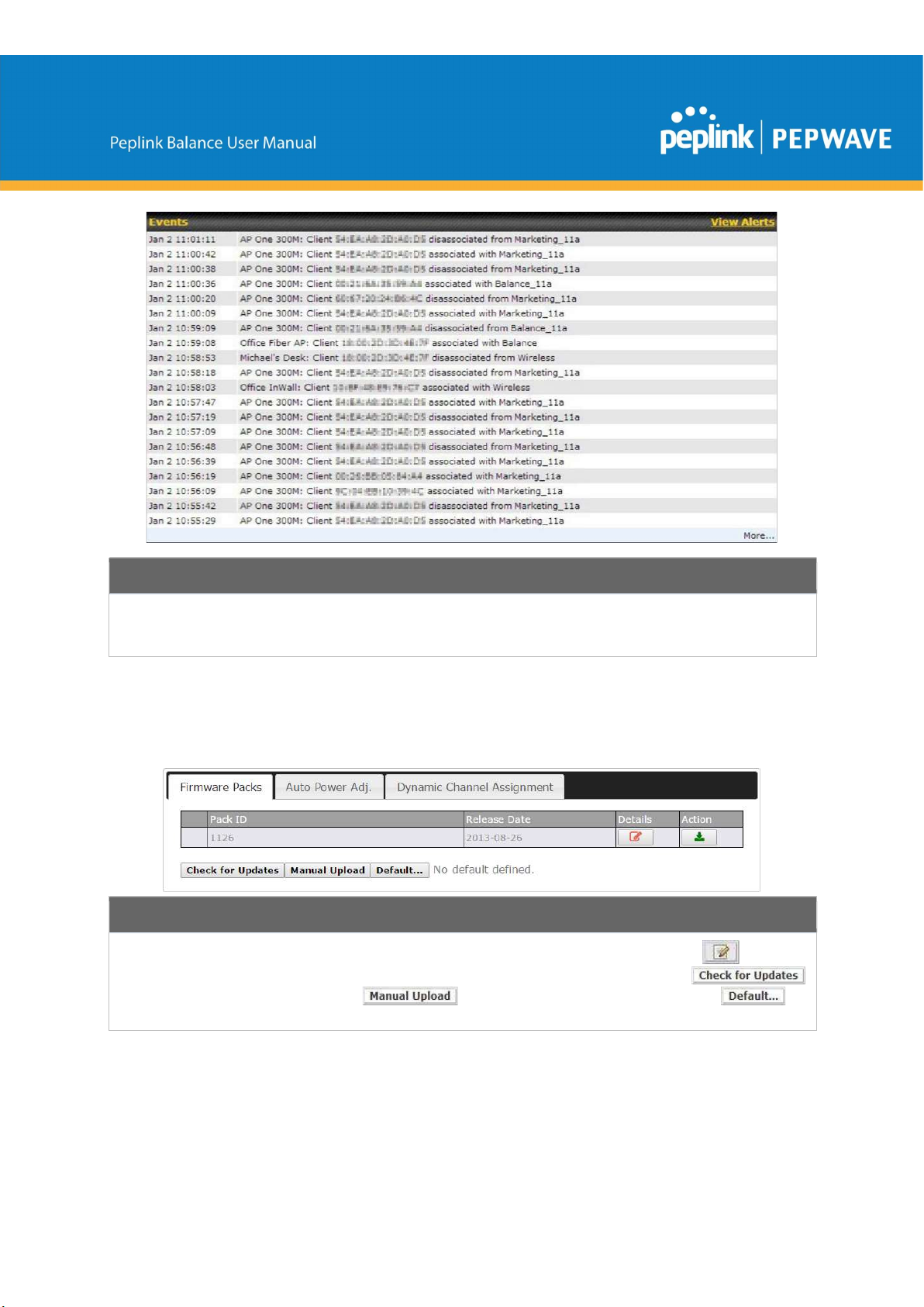
Events
This event log displays all activity on your AP network, down to the client level. Use to filter box to search by MAC
address, SSID, AP Serial Number, or AP Profile name. Click View Alerts to see only alerts, and click the More…
link for additional records.
11.3 Toolbox
Additional tools for managing firmware packs, power adjustment, and channel
assignment can be found at AP>Toolbox.
Firmware Packs
This is the first menu that will appear. Here, you can manage the firmware of your AP. Clicking on will display
information regarding each firmware pack. To receive new firmware packs, you can either press
to download new packs or you can press to manually upload a firmware pack. Press to
define which firmware pack is default.
https://www.peplink.com 139 Copyright @ 2019 Peplink
12
System Tab
12.1 System
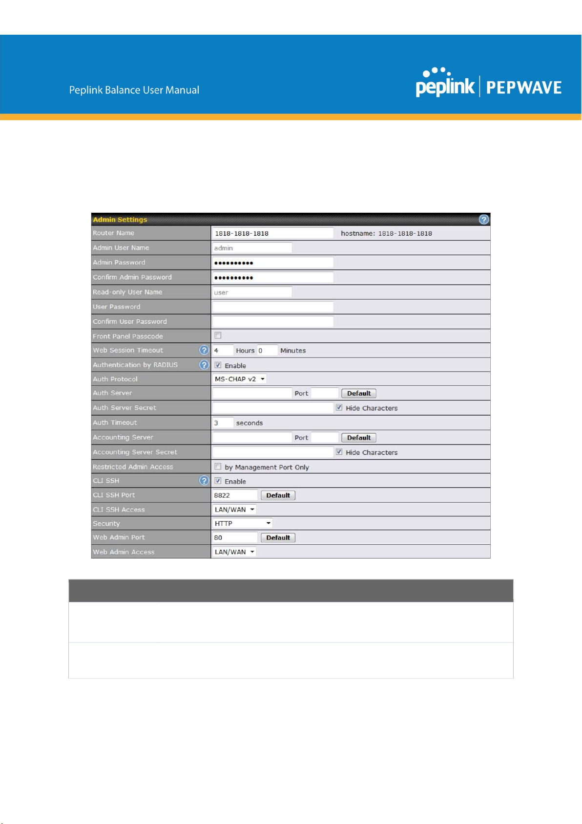
12.1.1 Admin Security
Admin Settings
This field allows you to define a name for this Peplink Balance unit. By default, Router
Router Name
Admin User
Name
https://www.peplink.com 140 Copyright @ 2019 Peplink
Name is set as Balance_XXXX, where XXXX refers to the last 4 digits of the serial number
of that balance unit.
Admin User Name is set as admin by default, but can be changed, if desired.

Admin
Password
Confirm Admin
Password
Read-only User
Name
User Password
Confirm User
Password
Front Panel
Passcode
Web Session
Timeout
Authentication
by RADIUS
This field allows you to specify a new administrator password.
This field allows you to verify and confirm the new administrator password.
Read-only User Name is set as user by default, but can be changed, if desired.
This field allows you to specify a new user password. Once the user password is set, the
read-only user feature will be enabled.
This field allows you to verify and confirm the new user password.
To require a 4-digit passcode to access front panel controls, check this box and then select
the code from the drop-down menus.
This field specifies the number of hours and minutes that a web session can remain idle
before the Balance terminates its access to the web admin interface. By default, it is set to 4
hours.
With this box is checked, the web admin will authenticate using an external RADIUS server.
Authenticated users are treated as either "admin" with full read-write permission or “user”
with read-only access. Local admin and user accounts will be disabled. When the device is
not able to communicate with the external RADIUS server, local accounts will be enabled
again for emergency access. Additional authentication options will be available once this
box is checked.
Auth Protocol
Auth Server
Auth Server
This specifies the authentication protocol used. Available options are MS-CHAP v2 and
PAP.
This specifies the access address and port of the external RADIUS server.
This field is for entering the secret key for accessing the RADIUS server.
Secret
Auth Timeout
Accounting
This option specifies the time value for authentication timeout.
This specifies the access address and port of the external accounting server.
Server
Accounting
This field is for entering the secret key for accessing the accounting server.
Server Secret
Network
Connection
https://www.peplink.com 141 Copyright @ 2019 Peplink
This option is for specifying the network connection to be used for authentication. Users can
choose from LAN, WAN, and VPN connections.

Restricted
Admin Access
CLI SSH &
Console
CLI SSH Port
CLI SSH
Access
Security
Web Admin
Port
Web Admin
Access
Check this box to restrict management to administrators connected to the management
port.
The CLI (command line interface) can be accessed via SSH. It can also be accessed from
the serial console port on some Peplink Balance models. This field enables CLI support. For
additional information regarding CLI, please refer to Section 22.5.
This field determines the port on which clients can access CLI SSH.
This menu allows you to choose between granting access to LAN and WAN clients, or to
LAN clients only.
This option is for specifying the protocol(s) through which the web admin interface can be
accessed:
● HTTP
● HTTPS
● HTTP/HTTPS
This field is for specifying the port number on which the web admin interface can be
accessed.
This option is for specifying the network interfaces through which the web admin interface
can be accessed:
● LAN only
● LAN/WAN
If LAN/WAN is chosen, the WAN Connection Access Settings form will be displayed.
Allowed LAN
LAN Connection Access Settings
This field allows you to permit only specific networks or VLANs to access the Web UI.
Networks
12.1.2 Firmware
The firmware of Peplink Balance is upgradeable through the web admin interface.
Firmware upgrade functionality is located at System>Firmware.
https://www.peplink.com 142 Copyright @ 2019 Peplink

There are two ways to upgrade the unit. The first method is through an online download. The
second method is to upload a firmware file manually.
To perform an online download, click on the Check for Firmware button. The Peplink Balance
will check online for new firmware. If new firmware is available, the Peplink Balance will
automatically download the firmware. The rest of the upgrade process will be automatically
initiated.
You may also download a firmware image from the Peplink website and update the unit
manually. To update using a firmware image, click Choose File to select the firmware file from
the local computer, and then click Manual Upgrade to send the firmware to the Peplink
Balance. It will then automatically initiate the firmware upgrade process.
Please note that all Peplink devices can store two different firmware versions in two different
partitions. A firmware upgrade will always replace the inactive partition. If you want to keep the
inactive firmware, you can simply reboot your device with the inactive firmware and then
perform the firmware upgrade.
Firmware Upgrade Status
Status LED Information during firmware upgrade:
● OFF – Firmware upgrade in progress (DO NOT disconnect power.)
● Red – Unit is rebooting
● Green – Firmware upgrade successfully completed
Important Note
The firmware upgrade process may not necessarily preserve the previous configuration, and the behavior varies on
a case-by-case basis. Consult the release notes for the particular firmware version before installing. Do not
disconnect the power during firmware upgrade process. Do not attempt to upload a non-firmware file or a firmware
file that is not supported by Peplink. Upgrading the Peplink Balance with an invalid firmware file will damage the unit
and may void the warranty.
12.1.3 Time
The time server functionality enables the system clock of the Peplink Balance to be
https://www.peplink.com 143 Copyright @ 2019 Peplink

synchronized with a specified time server. The settings for time server configuration are located
at System>Time.
Time Settings
This specifies the time zone (along with the corresponding Daylight Savings Time scheme)
Time Zone
in which Peplink Balance operates. The Time Zone value affects the time stamps in the
event log of the Peplink Balance and e-mail notifications. Check Show all to show all time
zone options.
Time Server
This setting specifies the NTP network time server to be utilized by the Peplink Balance.
12.1.4 Schedule
Enable and disable different functions (such as WAN connections, outbound policy, and firewalls
at different times, based on a user-scheduled configuration profile. The settings for this are
located at System > Schedule
Enable scheduling, and then click on your schedule name or on the New Schedule button to
begin.
https://www.peplink.com 144 Copyright @ 2019 Peplink

https://www.peplink.com 145 Copyright @ 2019 Peplink

Edit Schedule Profile
Enabling
Name
Schedule
Schedule Map
Click this checkbox to enable this schedule profile. Note that if this is disabled, then any
associated features will also have their scheduling disabled.
Enter your desired name for this particular schedule profile.
Click the drop-down menu to choose pre-defined schedules as your starting point. Please
note that upon selection, previous changes on the schedule map will be deleted.
Click on the desired times to enable features at that time period. You can hold your mouse
for faster entry.
12.1.5 Email Notification
The email notification functionality of the Peplink Balance provides a system administrator with
up-to-date information on network status. The settings for configuring email notification are
found at System>Email Notification.
Email Notification Settings
Email
Notification
https://www.peplink.com 146 Copyright @ 2019 Peplink
This setting specifies whether or not to enable email notification. If Enable is checked, the
Peplink Balance will send email messages to system administrators when the WAN status
changes or when new firmware is available. If Enable is not checked, email notification is
disabled and the Peplink Balance will not send email messages.

SMTP Server
SSL Encryption
SMTP Port
SMTP User
Name /
This setting specifies the SMTP server to be used for sending email. If the server requires
authentication, check Require authentication.
Check the box to enable SMTPS. When the box is checked, SMTP Port will be changed to
465 automatically.
This field is for specifying the SMTP port number. By default, this is set to 25; when SSL
Encryption is checked, the default port number will be set to 465. You may customize the
port number by editing this field. Click Default to restore the number to its default setting.
This setting specifies the SMTP username and password while sending email. These
options are shown only if Require authentication is checked in the SMTP Server setting.
Password
Confirm SMTP
Password
Sender’s Email
Address
Recipient’s
Email Address
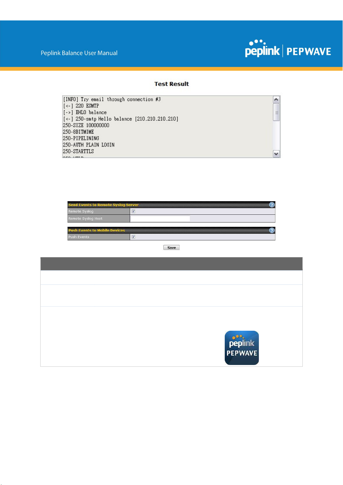
After you have finsihed setting up email notifications, you can click the Test Email Notification
button to test the settings before saving. After Test Email Notification is clicked, you will see
this screen to confirm the settings:
This field allows you to verify and confirm the new administrator password.
This setting specifies the email address which the Peplink Balance will use to send its
reports.
This setting specifies the email address(es) to which the Peplink Balance will send email
notifications. For multiple recipients, separate each email using the enter key.
Click Send Test Notification to confirm. In a few seconds, you will see a message with detailed
test results.
https://www.peplink.com 147 Copyright @ 2019 Peplink
12.1.6 Event Log
Event log functionality enables event logging at a specified remote syslog server. The settings
for configuring the remote system log can be found at System>Event Log.
Remote Syslog Settings
Remote Syslog
Remote Syslog
Host
Push Events
This setting specifies whether or not to log events at the specified remote syslog server.
This setting specifies the IP address or hostname of the remote syslog server.
The Peplink Balance can also send push notifications to mobile devices that have our
Mobile Router Utility installed. Check the box to activate this feature.
For more information on the Router Utility, go to:
www.peplink.com/products/router-utility
https://www.peplink.com 148 Copyright @ 2019 Peplink
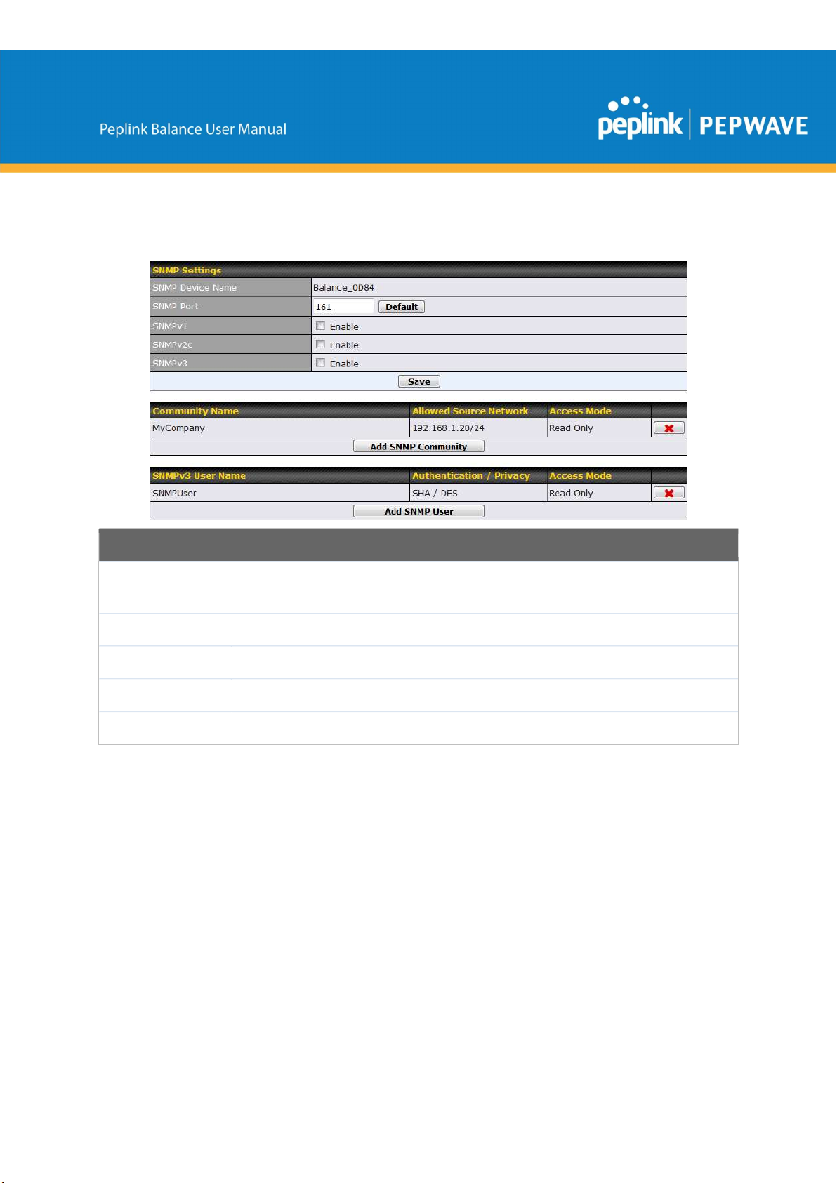
12.1.7 SNMP
SNMP or simple network management protocol is an open standard that can be used to collect
information about the Peplink Balance unit. SNMP configuration is located at System>SNMP.
SNMP Settings
SNMP Device
Name
SNMP Port
SNMPv1
SNMPv2
SNMPv3
This field shows the router name defined at System>Admin Security.
This option specifies the port which SNMP will use. The default port is 161.
This option allows you to enable SNMP version 1.
This option allows you to enable SNMP version 2.
This option allows you to enable SNMP version 3.
https://www.peplink.com 149 Copyright @ 2019 Peplink
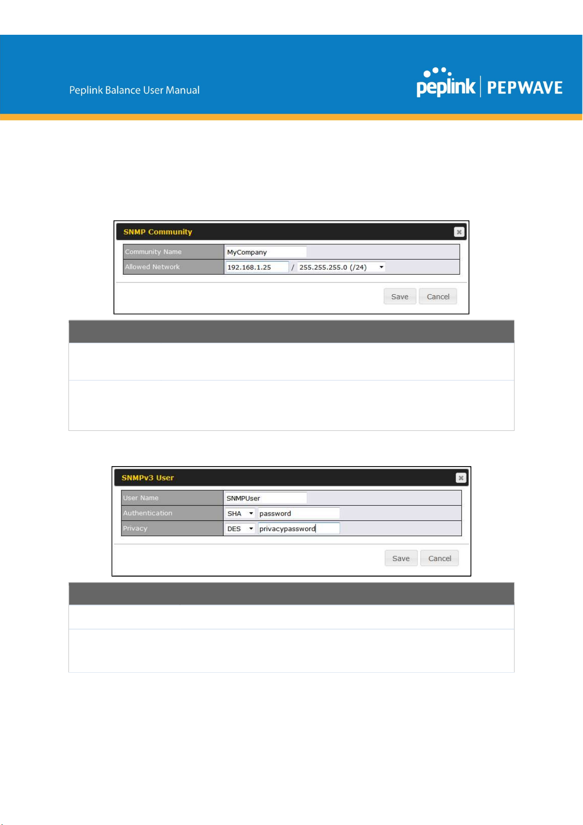
Allowed Source
To add a community for either SNMPv1 or SNMPv2, click the Add SNMP Community button in
the Community Name table, upon which the following screen is displayed:
SNMP Community Settings
Community
Name
Subnet
This setting specifies the SNMP community name.
This setting specifies a subnet from which access to the SNMP server is allowed. Enter
subnet address here (e.g., 192.168.1.0) and select the appropriate subnet mask.
Address
To define a user name for SNMPv3, click Add SNMP User in the SNMPv3 User Name table,
upon which the following screen is displayed:
SNMPv3 User Settings
User Name
Authentication
Protocol
This setting specifies a user name to be used in SNMPv3.
This setting specifies via a drop-down menu one of the following valid authentication
protocols:
● NONE
https://www.peplink.com 150 Copyright @ 2019 Peplink

● MD5
● SHA
When MD5 or SHA is selected, an entry field will appear for the password.
This setting specifies via a drop-down menu one of the following valid privacy
protocols:
Privacy Protocol
● NONE
● DES
When DES is selected, an entry field will appear for the password.
12.1.8 InControl
InControl is a cloud-based service which allows you to manage all of your Peplink and Pepwave
devices with one unified system. With it, you can generate reports, gather statistics, and
configure your devices automatically. All of this is now possible with InControl.
When this check box is checked, the device's status information will be sent to the Peplink
InControl system. This device's usage data and configuration will be sent to the system if you
enable the features in the system.
Alternately, you could also privately host InControl. Simply check the box beside the “Privately
Host InControl” open, and enter the IP Address of your InControl Host.
You can sign up for an InControl account at https://incontrol2.peplink.com. You can register your
devices under the account, monitor their status, see their usage reports, and receive offline
notifications.
https://www.peplink.com 151 Copyright @ 2019 Peplink
configure the LAN IP address of the Peplink Balance unit so that it is diff
erent from the HA
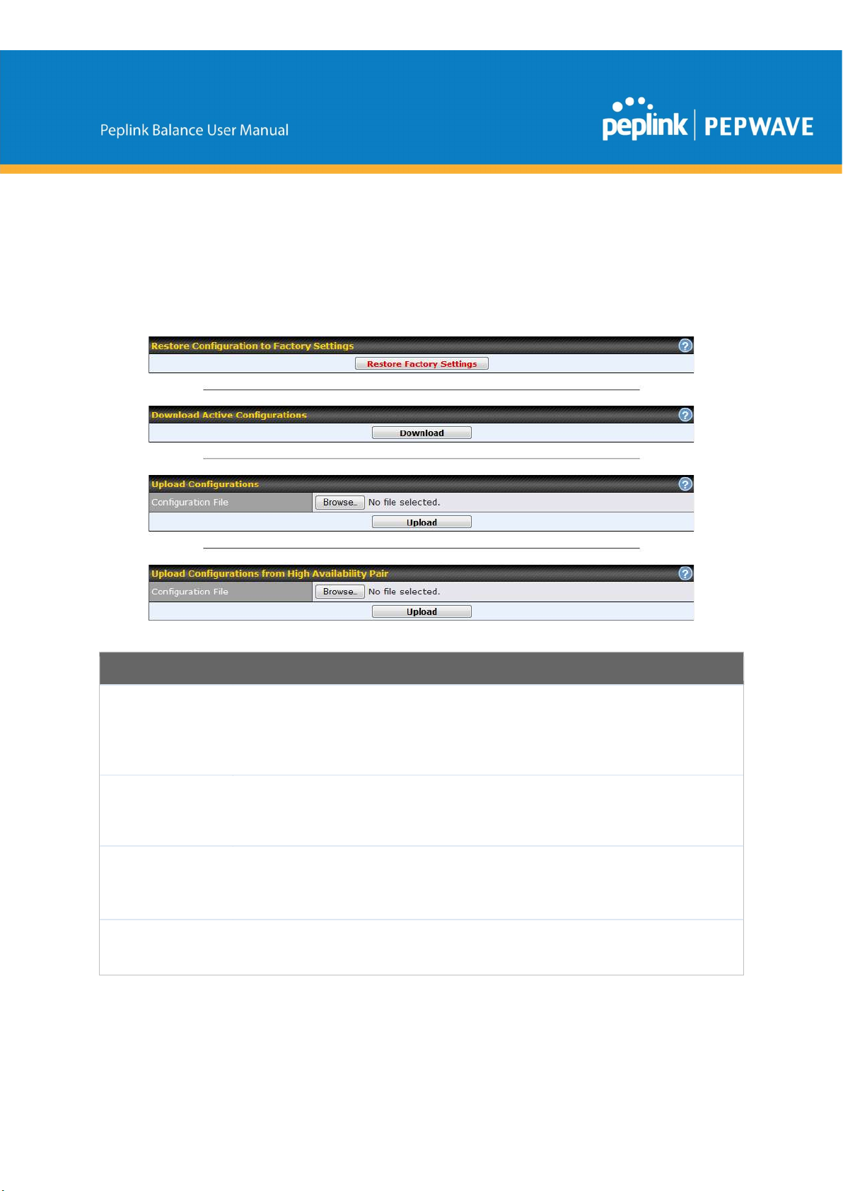
12.1.9 Configuration
Backing up Peplink Balance settings immediately after successful completion of initial setup is
strongly recommended. The functionality to download and upload Peplink Balance settings is
found at System>Configuration.
Configuration
Restore
Configuration
to Factory
The Restore Factory Settings button is to reset the configuration to factory default
settings. After clicking the button, you will need to click the Apply Changes button on the
top right corner to make the settings effective.
Settings
Download
Active
Click Download to backup the current active settings.
Configurations
Upload
Configurations
Upload
Configurations
https://www.peplink.com 152 Copyright @ 2019 Peplink
To restore or change settings based on a configuration file, click Choose File to locate the
configuration file on the local computer, and then click Upload. The new settings can then
be applied by clicking the Apply Changes button on the page header, or you can cancel
the procedure by pressing discard on the main page of the web admin interface.
In a high availability (HA) configuration, the Balance unit can quickly load the configuration
of its HA counterpart. To do so, click the Upload button. After loading the settings,

from High
counterpart.
Availability Pair
12.1.10 Feature Add-ons
Some balance models have features that can be activated upon purchase. Once the purchase
is complete, you will receive an activation key. Enter the key in the Activation Key field, click
Activate, and then click Apply Changes.
12.1.11 Reboot
This page provides a reboot button for restarting the system. For maximum reliability, the
Peplink Balance Series can equip with two copies of firmware, and each copy can be a different
version. You can select the firmware version you would like to reboot the device with. The
firmware marked with (Running) is the current system boot up firmware.
Please note that a firmware upgrade will always replace the inactive firmware partition.
https://www.peplink.com 153 Copyright @ 2019 Peplink

12.2 Tools
12.3 Ping
The ping test tool sends pings through a specific Ethernet interface or a SpeedFusionTM VPN
connection. You can specify the number of pings in the field Number of times to a maximum
number of 10 times. Packet Size can be set to a maximum of 1472 bytes. The ping utility is
located at System>Tools>Ping, illustrated below:
Tip
A system administrator can use the ping utility to manually check the connectivity of a particular LAN/WAN
connection.
12.4 Traceroute
The traceroute test tool traces the routing path to the destination through a particular Ethernet
interface or a SpeedFusion
System>Tools>Traceroute.
TM
connection. The traceroute test utility is located at
https://www.peplink.com 154 Copyright @ 2019 Peplink
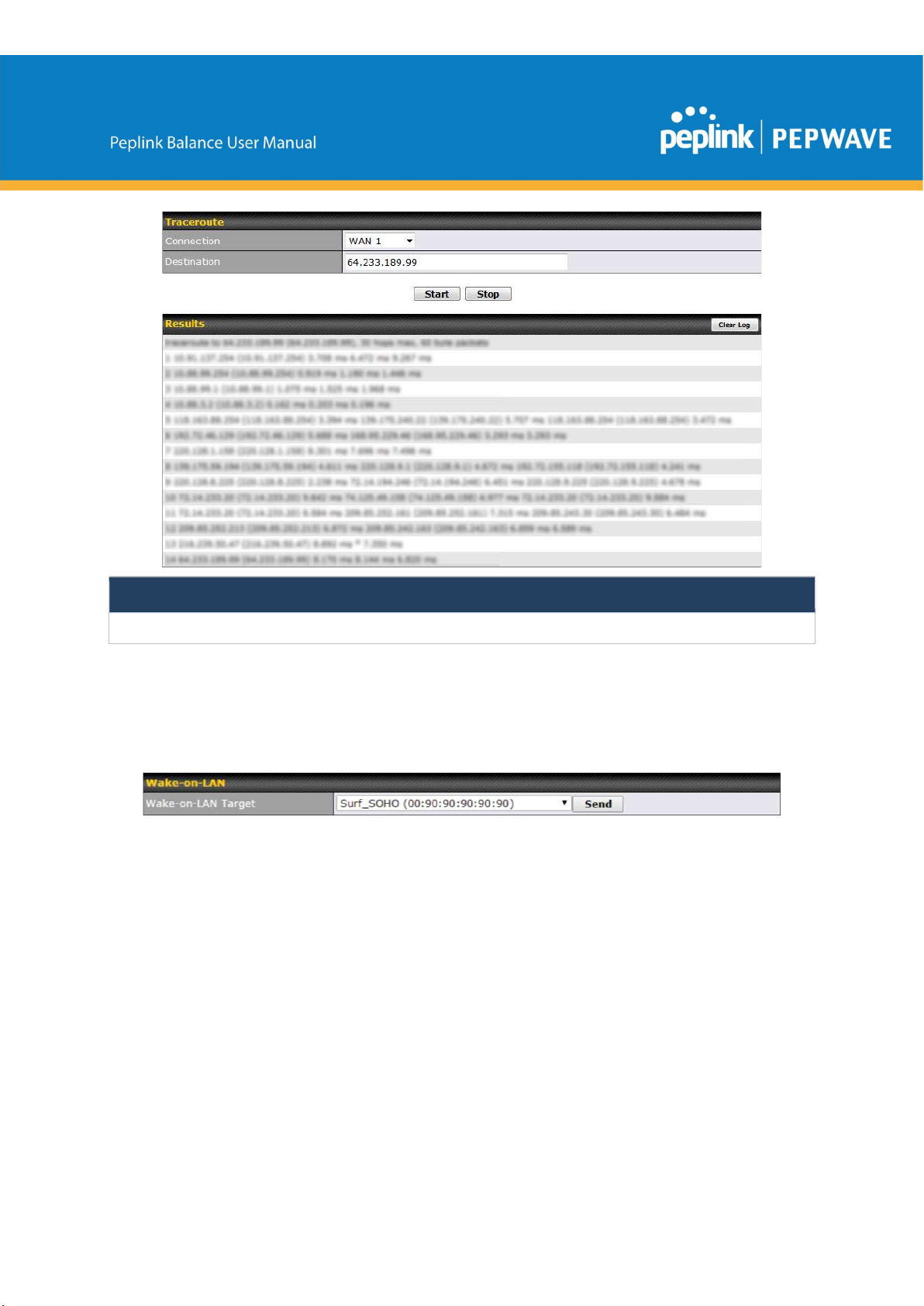
Tip
A system administrator can use the traceroute utility to analyze the connection path of a LAN/WAN connection.
12.5 Wake-on-LAN
Peplink routers can send special “magic packets” to any client specified from the Web UI. To
access this feature, navigate to System > Tools > Wake-on-LAN
Select a client from the drop-down list and click Send to send a “magic packet”
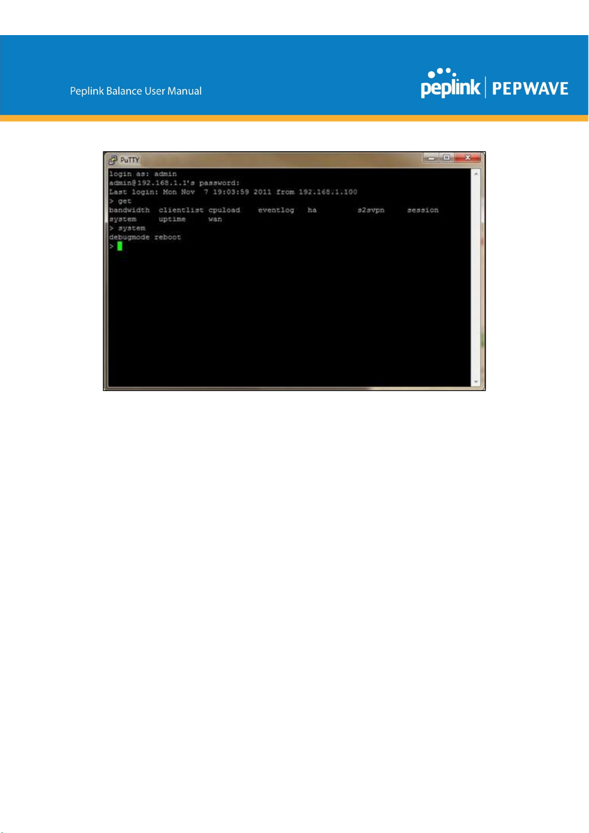
12.6 CLI (Command Line) Support
The serial console connector on some Peplink Balance units is RJ-45. To access the
serial console port, prepare a RJ-45 to DB-9 console cable. Connect the RJ-45 end to
the unit's console port and the DB-9 end to a terminal's serial port. The port setting will
be 115200,8N1.
The serial console connector on other Peplink Balance units is a DB-9 male connector.
To access the serial console port, connect a null modem cable with a DB-9 connector
on both ends to a terminal with the port setting of 115200,8N1.
https://www.peplink.com 155 Copyright @ 2019 Peplink
13
Status Tab
13.1 Status
13.1.1 Device
System information is located at Status>Device.
https://www.peplink.com 156 Copyright @ 2019 Peplink

https://www.peplink.com 157 Copyright @ 2019 Peplink

System Information
Router Name
Model
Hardware
Revision
Serial Number
Firmware
Uptime
System Time
Diagnostic
Report
Remote
Assistance
This is the name specified in the Router Name field located at System>Admin Security.
This shows the model name and number of this device.
This shows the hardware version of this device.
This shows the serial number of this device.
This shows the firmware version this device is currently running.
This shows the length of time since the device has been rebooted.
This shows the current system time.
The Download link is for exporting a diagnostic report file required for system investigation.
Click Turn on to enable remote assistance.
The second table shows the MAC address of each LAN/WAN interface connected.
Important Note
If you encounter issues and would like to contact the Peplink Support Team (http://www.peplink.com/contact/),
please download the diagnostic report file and attach it along with a description of your issue. In Firmware 5.1 or
before, the diagnostic report file can be obtained at System>Reboot.
13.1.2 Active Sessions
Information on active sessions can be found at Status>Active Sessions>Overview.
https://www.peplink.com 158 Copyright @ 2019 Peplink

This screen displays the number of sessions initiated by each application. Click on each
service listing for additional information. This screen also indicates the number of
sessions initiated by each WAN port. Finally, you can see which clients are initiating the
most sessions.
https://www.peplink.com 159 Copyright @ 2019 Peplink

In addition, you can also perform a filtered search for specific sessions. You can filter by
subnet, port, protocol, and interface. To perform a search, navigate to Status>Active
Sessions>Search.
This Active Sessions section displays the active inbound / outbound sessions of each
WAN connection on the Peplink Balance. A filter is available to help sort out the active
session information. Enter a keyword in the field or check one of the WAN connection
boxes for filtering.
13.1.3 Client List
The client list table is located at Status>Client List. It lists DHCP and online client IP
addresses, names (retrieved from the DHCP reservation table or defined by users),
current download and upload rate, and MAC address.
Clients can be imported into the DHCP reservation table by clicking the button on
the right. Further update the record after the import by going to Network>LAN.
https://www.peplink.com 160 Copyright @ 2019 Peplink

If the PPTP server SpeedFusionTM, or AP controller is enabled, you may see the
corresponding connection name listed in the Name field.
13.1.4 WINS Clients
The WINS client list table is located at Status>WINS Client.
The WINS client table lists the IP addresses and names of WINS clients. This option will
only be available when you have enabled the WINS server The names of clients
retrieved will be automatically matched into the Client List (see previous section). Click
Flush All to flush all WINS client records.
13.1.5 OSPF & RIPv2
Information on OSPF and RIPv2 routing setup can be found at Status>OSPF & RIPv2.
13.1.6 MediaFast
To get details on storage and bandwidth usage, select Status>MediaFast.
https://www.peplink.com 161 Copyright @ 2019 Peplink

13.1.7 SpeedFusion Status
Current SpeedFusionTM status information is located at Status>SpeedFusionTM.
Details about SpeedFusion
https://www.peplink.com 162 Copyright @ 2019 Peplink
TM
connection peers appears as below:

Click on the corresponding peer name to explore the WAN connection(s) status and
subnet information of each VPN peer.
Click the button for a chart displaying real-time throughput, latency, and droprate information for each WAN connection.
https://www.peplink.com 163 Copyright @ 2019 Peplink
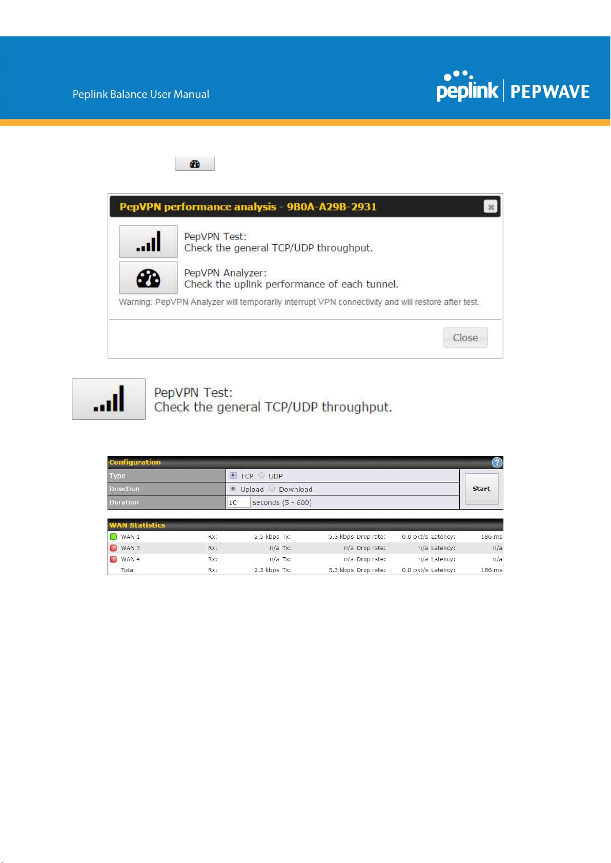
When pressing the button, the following menu will appear:
After clicking the icon, the following menu appears:
Select the L2 protocol (TCP/UDP), direction, and duration and click the Start button to
begin the general throughput test.
https://www.peplink.com 164 Copyright @ 2019 Peplink

The bandwidth bonding feature of PepVPN occurs when multiple WAN lines from one
end merge with multiple WAN lines from the other end. For this to happen, each WAN
line needs to form a connection with all the WAN lines on the opposite end. The function
of the PepVPN analyzer is to report the throughput, packet loss, and latency of all
possible combinations of connections. Please note that the PepVPN Analyzer will
temporarily interrupt VPN connectivity and will restore after test.
After clicking the icon, the analyzer will require several minutes to perform its analysis
depending the number of WAN links in the SpeedFusionTM Tunnel. Once the test the
complete, the report will appear:
https://www.peplink.com 165 Copyright @ 2019 Peplink
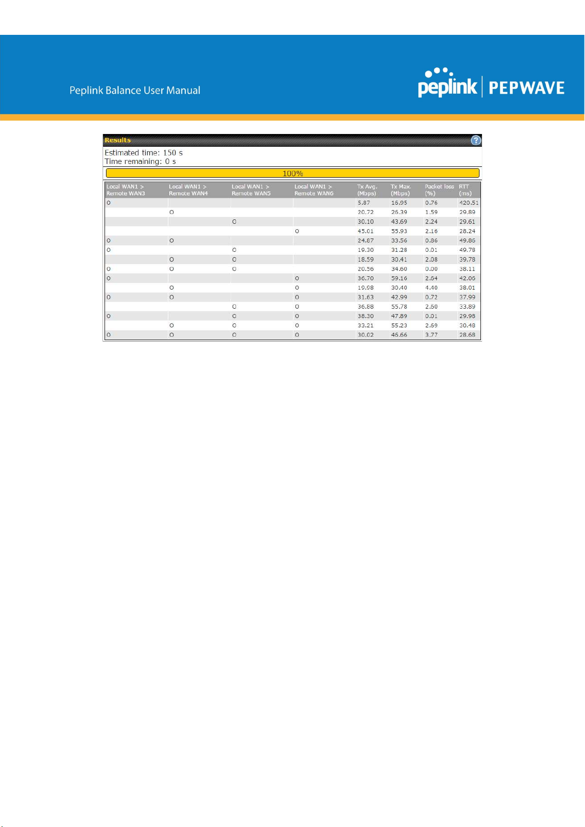
"O" indicates that specific WAN / Tunnel is active for that particular test.
"Tx Avg." is the averaged throughput across the full 10 seconds time, while "Tx Max." is
the averaged throughput of the fastest 30% of time.
13.1.8 Event Log
Event log information is located at Status>Event Log.
https://www.peplink.com 166 Copyright @ 2019 Peplink
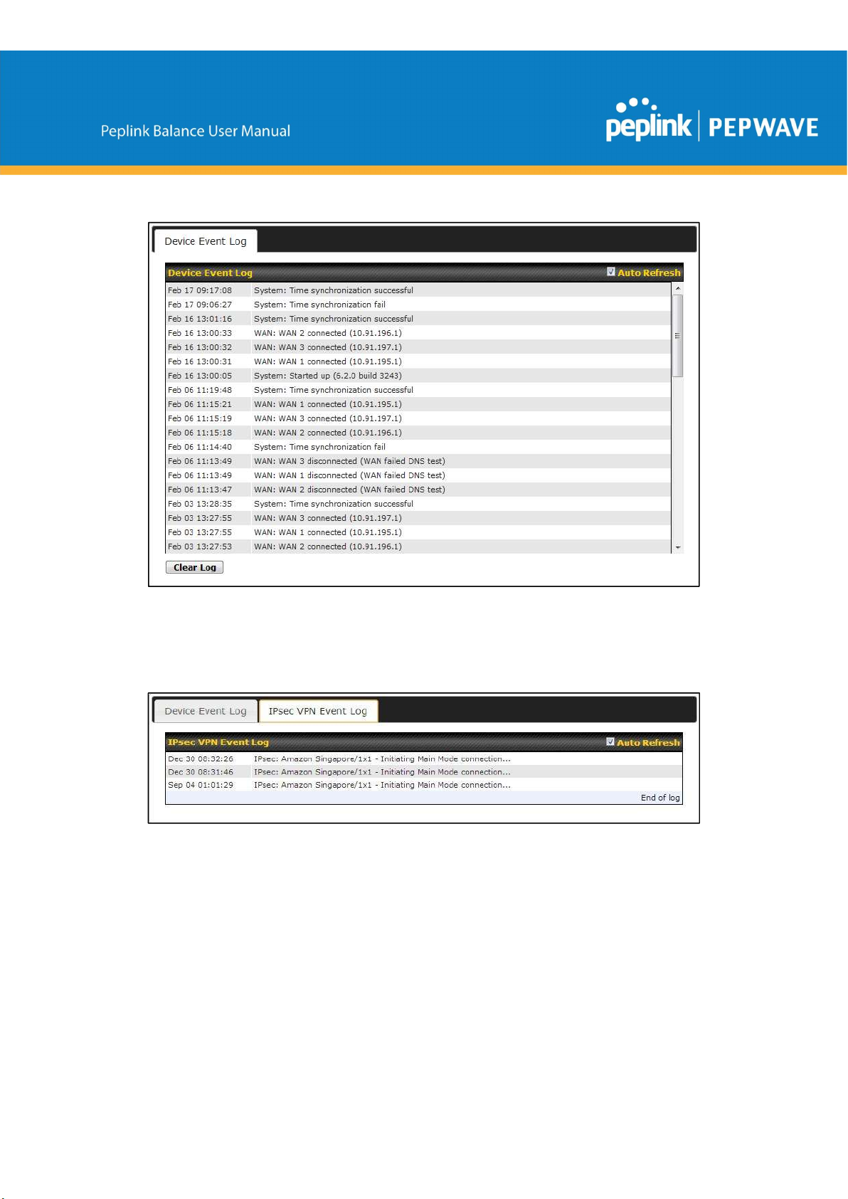
Device Event Log
The log section displays a list of events that has taken place on the Peplink Balance
unit. Check Auto Refresh to refresh log entries automatically. Click the Clear Log
button to clear the log.
IPsec Event Log
This section displays a list of events that has taken place within an IPsec VPN
connection. Check the box next to Auto Refresh and the log will be refreshed
automatically. For an AP event log, navigate to AP>Info.
13.2 Bandwidth
This section shows the bandwidth usage statistics, located at Status>Bandwidth.
https://www.peplink.com 167 Copyright @ 2019 Peplink
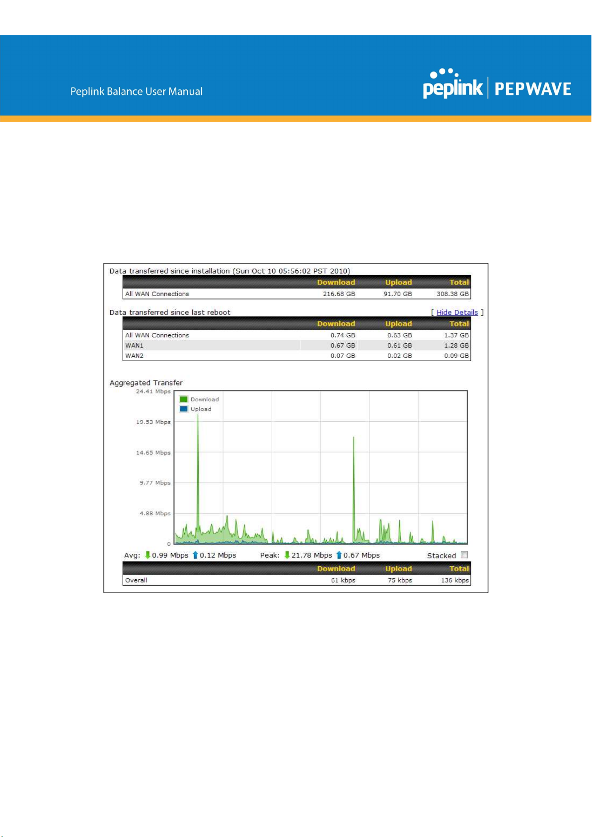
Bandwidth usage at the LAN while the device is switched off (e.g., LAN bypass) is
neither recorded nor shown.
13.2.1 Real-Time
The Data transferred since installation table indicates how much network traffic has
been processed by the device since the first bootup. The Data transferred since last
reboot table indicates how much network traffic has been processed by the device
since the last bootup.
https://www.peplink.com 168 Copyright @ 2019 Peplink
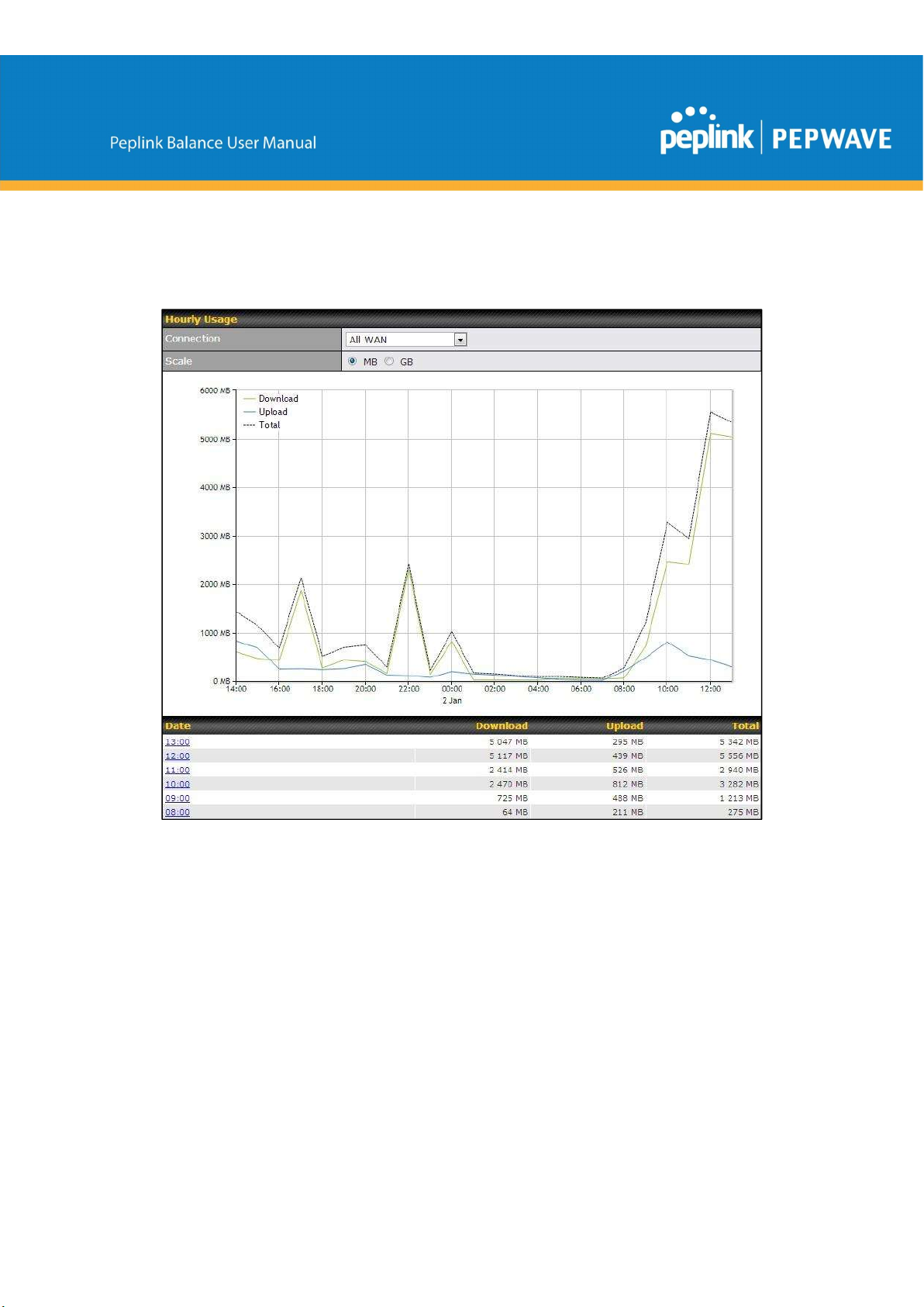
13.2.2 Hourly
This page shows the hourly bandwidth usage for all WAN connections, with the option
of viewing each individual connection. Select the desired connection to check from the
drop-down menu.
13.2.3 Daily
This page shows the daily bandwidth usage for all WAN connections, with the option of
viewing each individual connection.
Select the connection to check from the drop-down menu. If you have enabled the
Bandwidth Monitoring feature as shown in Section 13.4, the Current Billing Cycle
table for that WAN connection will be displayed.
Click on a date to view the client bandwidth usage of that specific date. This feature is
not available if you have selected to view the bandwidth usage of only a particular WAN
connection. The scale of the graph can be set to display megabytes (MB) or gigabytes
https://www.peplink.com 169 Copyright @ 2019 Peplink
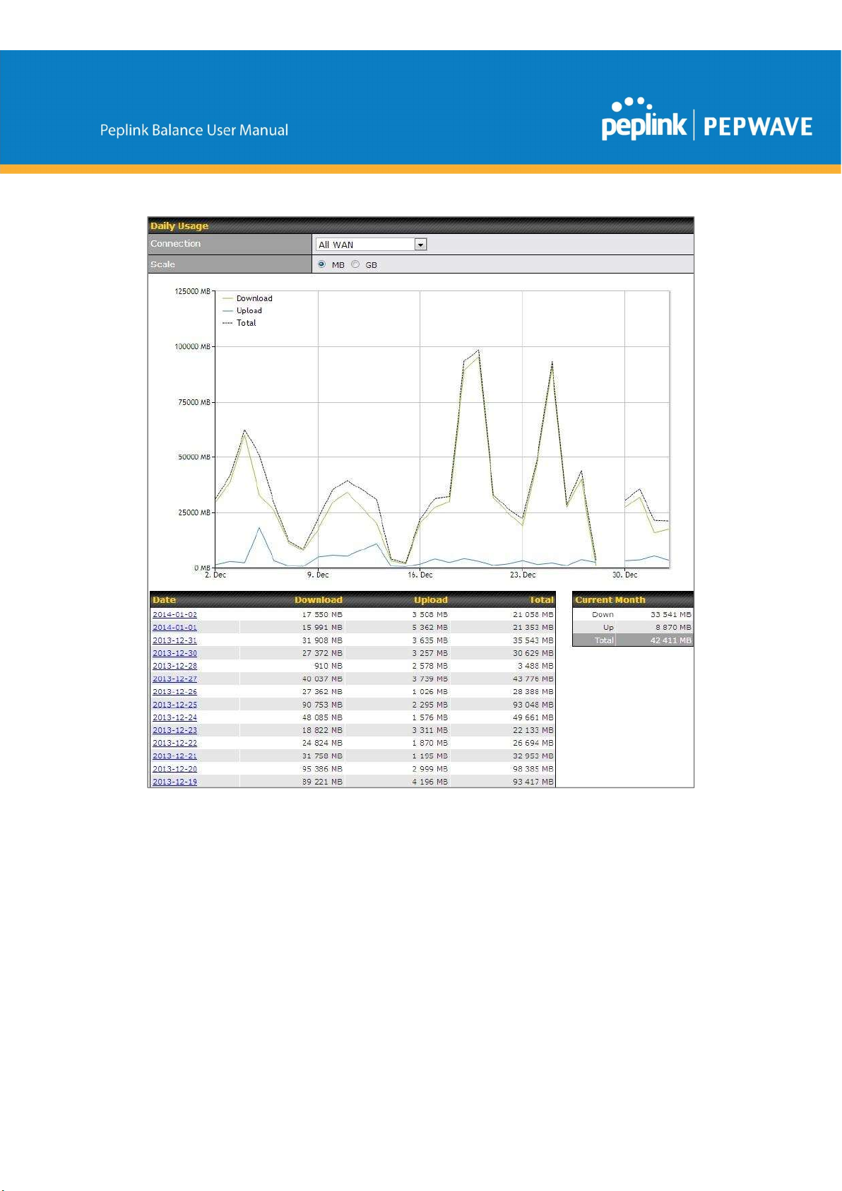
(GB).
Status
https://www.peplink.com 170 Copyright @ 2019 Peplink
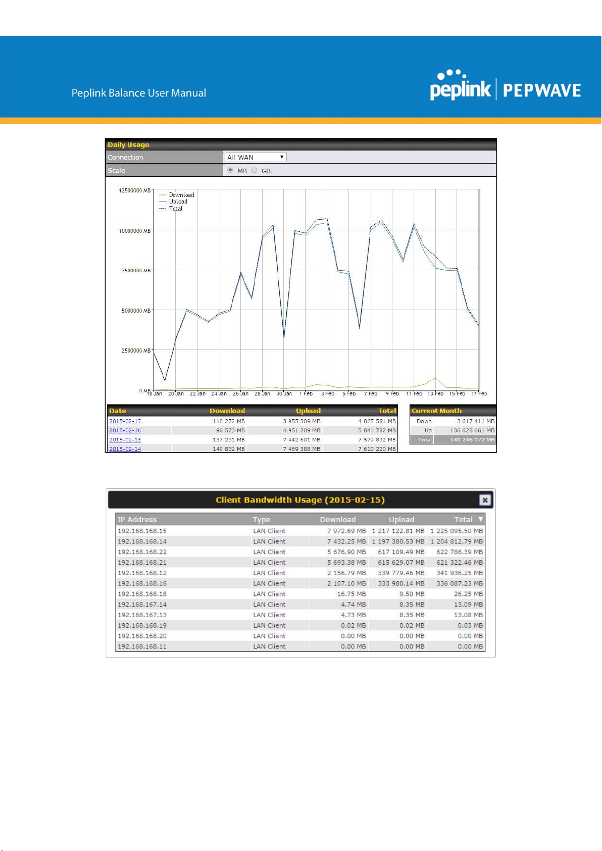
Click on a specific date to receive a breakdown of all client usage for that date.
https://www.peplink.com 171 Copyright @ 2019 Peplink
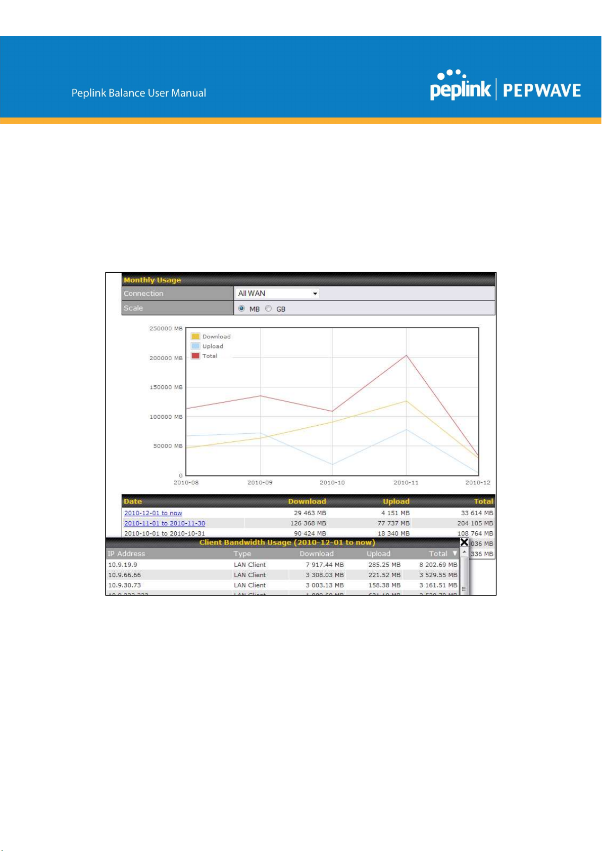
13.2.4 Monthly
This page shows the monthly bandwidth usage for each WAN connection. If you have
enabled Bandwidth Monitoring feature as shown in Section 13.4, you can check the
usage of each particular connection and view the information by Billing Cycle or by
Calendar Month.
Click the first two rows to view the client bandwidth usage in the last two months. This
feature is not available if you have chosen to view the bandwidth of an individual WAN
connection. The scale of the graph can be set to display megabytes (MB) or gigabytes
(GB).
Click on a specific month to receive a breakdown of all client usage for that month.
https://www.peplink.com 172 Copyright @ 2019 Peplink

Appendix A. Restoration of Factory Defaults
To restore the factory default settings on a Peplink Balance unit, perform the following:
For Balance models with a reset button:
1. Locate the reset button on the Peplink Balance unit.
2. With a paper clip, press and keep the reset button pressed for at least 10
seconds, until the unit reboots itself.
For Balance/MediaFast models with an LCD menu:
● Use the buttons on front panel to control the LCD menu to go to
Maintenance>Factory Defaults, and then choose Yes to confirm.
Afterwards, the factory default settings will be restored.
Important Note
All user settings will be lost after restoring the factory default settings. Regular backup of configuration
parameters is strongly recommended.
Appendix B. Routing under DHCP, Static IP, and PPPoE
The information in this appendix applies only to situations where the Peplink Balance
operates a WAN connection under DHCP, Static IP, or PPPoE.
B.1
When the Peplink Balance is operating under NAT mode, the source IP addresses of
outgoing IP packets are translated to the WAN IP address of the Peplink Balance. With
NAT, all LAN devices share the same WAN IP address to access the Internet (i.e., the
WAN IP address of the Peplink Balance).
Operating the Peplink Balance in NAT mode requires only one WAN (Internet) IP
address. In addition, operating in NAT mode also has security advantages because
LAN devices are hidden behind the Peplink Balance. They are not directly accessible
from the Internet and hence less vulnerable to attacks.
The following figure shows the packet flow in NAT mode:
https://www.peplink.com 173 Copyright @ 2019 Peplink
Routing Via Network Address Translation (NAT)

B.2
Routing Via IP Forwarding
When the Peplink Balance is operating under IP forwarding mode, the IP addresses of
IP packets are unchanged; the Peplink Balance forwards both inbound and outbound IP
packets without changing their IP addresses.
The following figure shows the packet flow in IP forwarding mode:
https://www.peplink.com 174 Copyright @ 2019 Peplink

Appendix C. Case Studies
MPLS Alternative
Our SpeedFusion enabled routers can be used to bond multiple low-cost/commodity Internet
connections to replace an expensive managed business Internet connection, private leased line,
MPLS, and frame relay without sacrificing reliability and availability.
Belows are typical deployment for using our Balance routers to replace expensive MPLS
connection with commodity connections, such as ADSL, 3G, and 4G LTE links.
Special features of Balance 580: have high availability capability
Special features of Balance 2500: have high availability capability and capable of connecting to
optical fiber based LAN through SFP+ connector
Our WAN-bonding routers which comprise our Balance series and MediaFast series
are capable of connecting multiple devices, and end users’ networks to the Internet through
multiple Internet connections.
Our MediaFast series routers have been helping students at many education institutions to
enjoy uninterrupted learning
https://www.peplink.com 175 Copyright @ 2019 Peplink

Option 1: MPLS Supplement
Affordably increase your bandwidth by adding commodity ADSL links to your MPLS connection.
SpeedFusion technology bonds all your connections together, enabling session-persistent, usertransparent hot failover. QoS support, bandwidth control, and traffic prioritization gives you total
control over your network.
https://www.peplink.com 176 Copyright @ 2019 Peplink

Option 2: MPLS Alternative
Achieve faster speeds and greater reliability while paying only 20% of MPLS costs by connecting
multiple ADSL, 3G, and 4G LTE links. Choose a topology that suits your requirements: a hub-andspoke topology maximizes control over your network, while a meshed topology can reduce your
bandwidth overhead by enabling your devices to form Unbreakable VPN connections directly with
each other.
https://www.peplink.com 177 Copyright @ 2019 Peplink

Here is an example of to supplement of existing Multi-Office MPLS network with DSL bonding
through SpeedFusion using a Balance 580 at the headquarters and Balance 210/310 at branch
offices.
Environment:
- This organization has one head office with and two branch offices, with most of
the crucial information stored in a server room at the head office.
- They are connecting the offices together using a managed MPLS Solution.
However, the MPLS Network is operating at capacity and upgrading the links is
cost prohibitive.
- As the organization grows, it needs a cost-efficient way to to add more bandwidth
to its wide area network.
- Internet access at the remote sites is sent via a web proxy at head office for
corporate web filtering compliance.
Requirement:
- User sessions need to remain uninterrupted
- More bandwidth is required at the head office location for direct internet access.
Recommended Solution:
- Form a SpeedFusion tunnel between the branch offices and head office to bond
the MPLS and additional DSL lines.
- SpeedFusion allows for hot failover, maintaining a persistent session while
switching connections.
https://www.peplink.com 178 Copyright @ 2019 Peplink

- The DSLs at head office can be used for direct internet access providing lots of
cheap internet bandwidth.
- Head office can use outbound policies to send internet traffic out over the DSLs
and only use the MPLS connection for speedfusion, freeing up bandwidth.
Devices Deployed: Balance 210, Balance 310, Balance 580
Harrington Industrial Plastics
Overview
Harrington Plastics, the US’s largest industrial plastics distributor, was looking to
upgrade its network equipment. Harrington’s team came across Peplink and started
thinking about MPLS alternatives. By choosing Peplink, they saved a fortune on
upgrades and ended up with yearly savings of up to $100,000.
Requirements
Zero network outages
-
Flexible resilience options
-
Cost-effective solution
-
Solution
Peplink Balance 1350
-
https://www.peplink.com 179 Copyright @ 2019 Peplink

Peplink Balance 380
-
Unbreakable VPN
-
Benefits
-
Extreme savings of $100,000 per year
4x the bandwidth
-
Seamless hardware failover
-
Highly available network due to WAN diversity
-
-
Highly cost-effective compared to competing solutions
Easy resilience achieved by adding 4G USB modems
-
Time For An Upgrade
Harrington Industrial Plastics decided it was time to upgrade its network equipment. Its
existing solution used redundant MPLS for site-to-site traffic and broadband connections
for Internet access. Harrington is the US’s largest distributor of industrial plastics piping,
serving all industries with corrosive and high-purity applications. It requires peak
performance at all times in order to serve its large customer base and 43 busy branches.
Quick Deployment and Unbreakable Connectivity
In evaluating an upgrade to its network infrastructure, it was only natural that Harrington
settled on the best in the industry — Peplink. Peplink partner Frontier Computer
Corporation was chosen to help design and deploy the solution. Since Peplink gear is so
easy to configure and install, Harrington was able to design, prototype and roll out the
entire solution to the corporate headquarters and all 43 branches within just one year.
https://www.peplink.com 180 Copyright @ 2019 Peplink
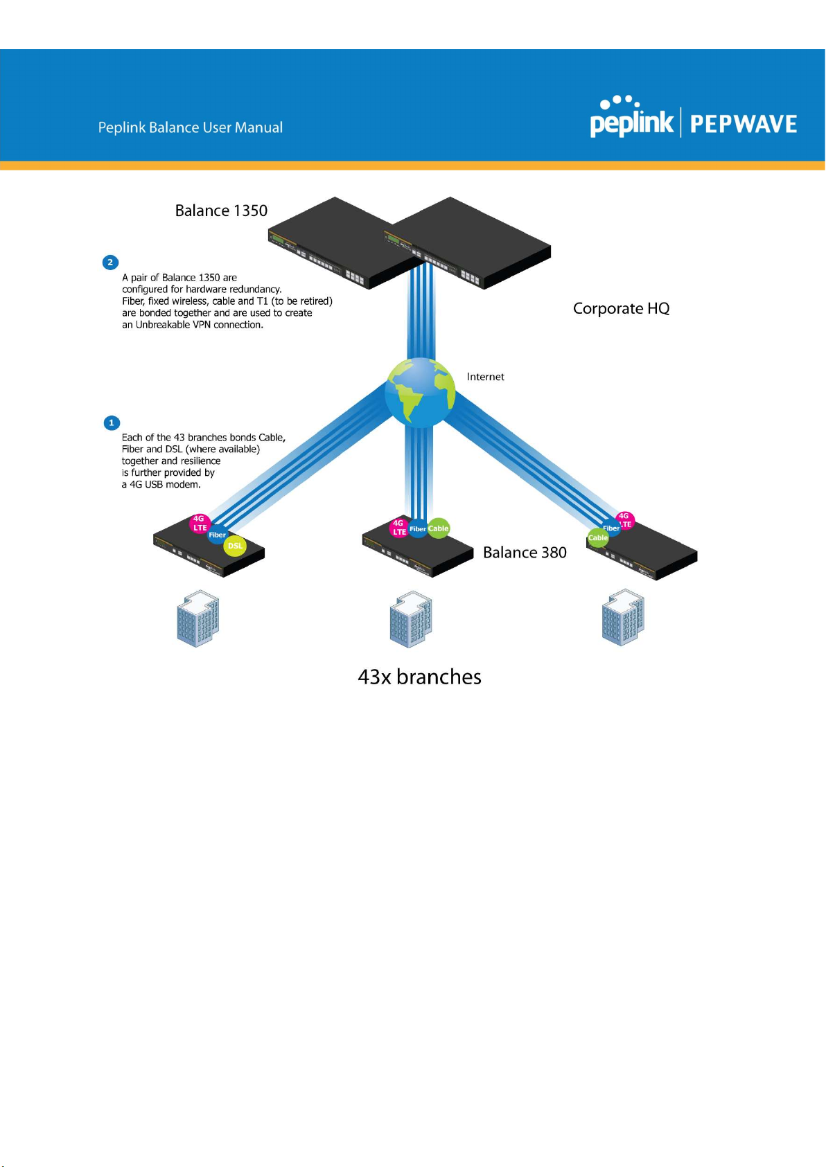
The corporate office houses a pair of redundant Balance 1350s for hardware resilience.
Served by 4 separate links from multiple service providers, the network’s chance of an
outage is practically zero. All 43 branches are now equipped with a fleet of Balance 380s,
bonding a combination of DSL, cable and fiber-optic links together with an additional 4G
USB modem for added resilience. These work together to create an Unbreakable VPN
connection to the Balance 1350s at the corporate office, connecting the final dot.
Dependable, Resilient Networking that’s also Very Budget-friendly
https://www.peplink.com 181 Copyright @ 2019 Peplink

Harrington Industrial Plastics couldn’t be happier. They now benefit from an extremely
reliable and cost-effective network. Supplying additional resilience is as easy as plugging
in a 4G USB modem. Where the MPLS 768kb deployed previously had cost them
$192000 a year for all 40 sites, their new solution is now only costing them $92000. Their
total bandwidth has been bumped from 36 Mbps to 138 Mbps.
PLUSS
Peplink + Citrix + VoIP Adds Up to Fast, Cost-Effective WAN for Pluss
A Peplink customer since 2006, Pluss is a social enterprise that each year makes
gainful employment a reality for more than 5000 disabled and disadvantaged UK
citizens. With 37 locations and 300+ active users, Pluss makes heavy use of its WAN
infrastructure, which until recently was built on managed MPLS lines.
Hoping to cut expenses and, if possible, boost performance at the same time, Steve
Taylor, IT Manager at Pluss, set out to find a solution that would allow Pluss to replace
costly MPLS service with a commodity alternative, such as DSL or EFM.
https://www.peplink.com 182 Copyright @ 2019 Peplink
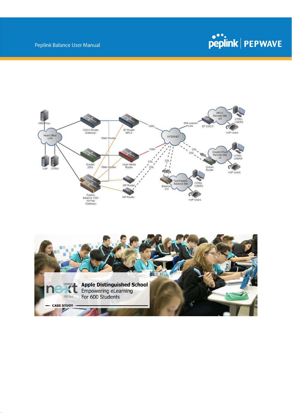
Steve found the solution Pluss needed in Peplink products, especially the Balance
series of high-performance enterprise routers and SpeedFusion bonding technology.
Pluss now powers its entire WAN infrastructure with simple-to-install, highly reliable,
and cost-effective Peplink gear, which allows it to aggregate DSL and other commodity
connections and replace expensive leased lines.
Colégio Next - Enabling eLearning
Colégio Next, a recognized Apple Distinguished School - deploys over 500 iPads to its
600 students as a teaching and learning tool.
https://www.peplink.com 183 Copyright @ 2019 Peplink

Despite being equipped with iPads, teachers and students alike were not making use of
them. The reason for this was because of the slow network access speeds. Apps would
not download and course contents were inaccessible. Often, having more than a couple
students connected to the same Wi-Fi access point was enough to bring it to its knees.
Colégio Next needed a unique solution, so they contacted Peplink.
Requirements
- Solve network congestion problem caused by 600 students over rural Internet
connections
- Wi-Fi that can handle 50+ users per classroom
- An affordable network infrastructure that can provide simultaneous access to mediarich educational content
Solution
- Peplink MediaFast
- Multi-WAN Content-caching router, tailor-made for Education networking.
- AP One 300M
- Enterprise grade AP, 5GHz Wi-Fi, up to 60 concurrent users.
Benefits
- Instant, simultaneous access to media-rich educational content for 500+ iPads
- Wi-Fi connection stability for 50+ users per classroom, not achievable by other tested
equipment
- Teachers, students and guests can be assigned access priority to available
bandwidth, further preventing congestion
- iOS updates (often 2GB size) no longer congest the network as they are downloaded
only once, cached on the MediaFast and then distributed to all iOS devices
- AP Controller makes MAC Address Filtering easy. Students are assigned to
designated APs by their devices' MAC Address in order to prevent saturating any
single AP.
- Flawless iPad AirPlay mirroring at all times
- iPads are used all day, reaching their full potential with a fast and stable network all
the time
https://www.peplink.com 184 Copyright @ 2019 Peplink
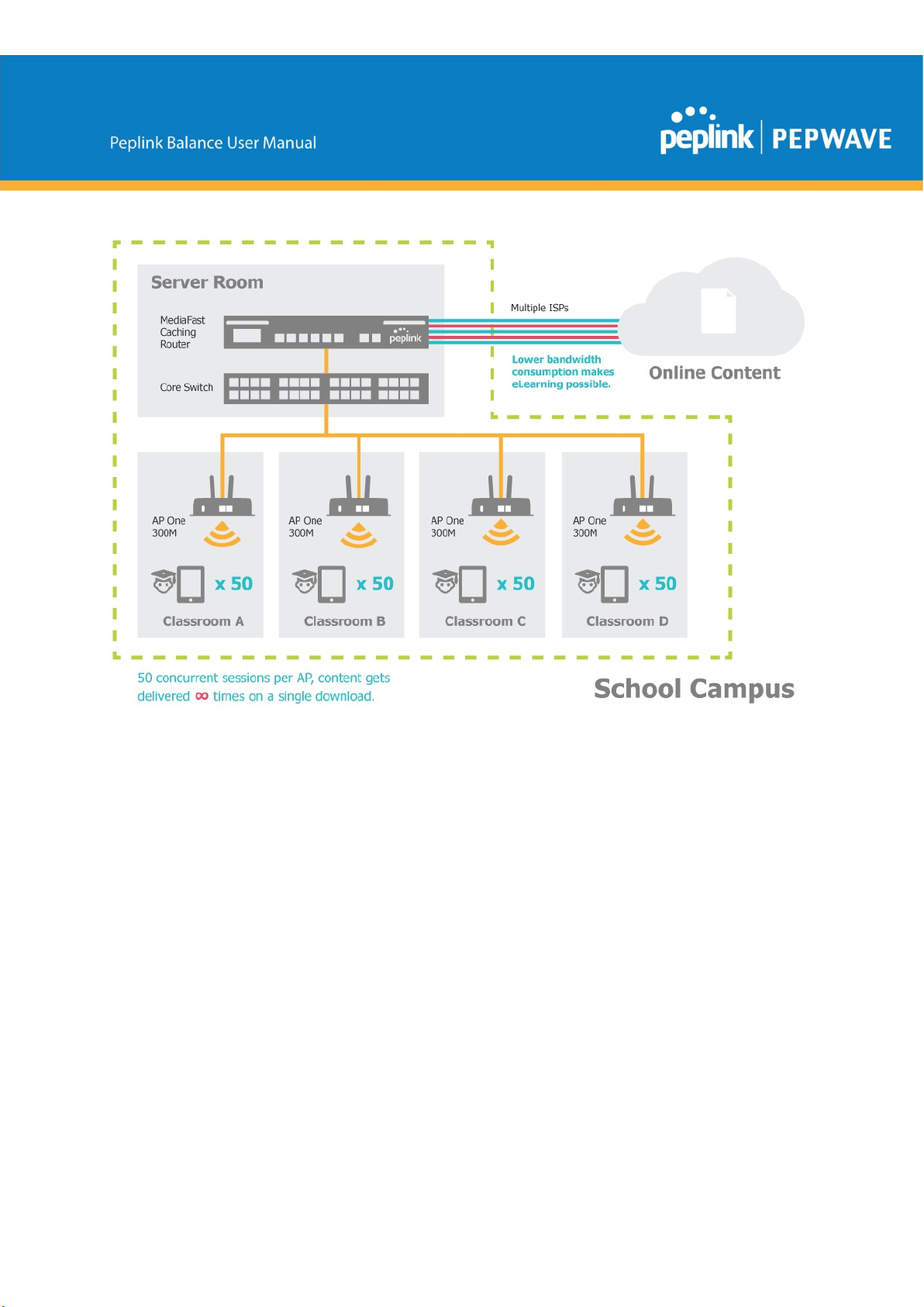
- Students are far more engaged and teachers rely on their iPads all day
https://www.peplink.com 185 Copyright @ 2019 Peplink

Performance Optimization
Scenario
In this scenario, email and web browsing are the two main Internet services used by
LAN users.
The mail server is external to the network. The connections are ADSL (WAN1, with slow
uplink and fast downlink) and Metro Ethernet (WAN2, symmetric).
Solution
For optimal performance with this configuration, individually set the WAN load balance
according to the characteristics of each service.
● Web browsing mainly downloads data; sending e-mails mainly consumes upload
bandwidth.
● Both connections offer good download speeds; WAN2 offers good upload
speeds.
● Define WAN1 and WAN2's inbound and outbound bandwidths to be 3M/512k
and 4M/4M, respectively. This will ensure that outbound traffic is more likely to
be routed through WAN2.
● For HTTP, set the weight to 3:4.
● For SMTP, set the weight to 1:8, such that users will have a greater chance to be
routed via WAN2 when sending e-mail.
Maintaining the Same IP Address Throughout a Session
Scenario
Some IP address-sensitive websites (for example, Internet banking) use both client IP
address and cookie matching for session identification. Since load balancing uses
different IP addresses, the session is dropped when a mismatched IP is detected,
resulting in frequent interruptions while visiting such sites.
Solution
Make use of the persistence functionality of the Peplink Balance. With persistence
configured and the By Destination option selected, the Peplink Balance will use a
consistent WAN connection for source-destination pairs of IP addresses, preventing
sessions from being dropped.
With persistence configured and the option By Source is selected, the Peplink Balance
uses a consistent WAN connection for same-source IP addresses. This option offers
https://www.peplink.com 186 Copyright @ 2019 Peplink
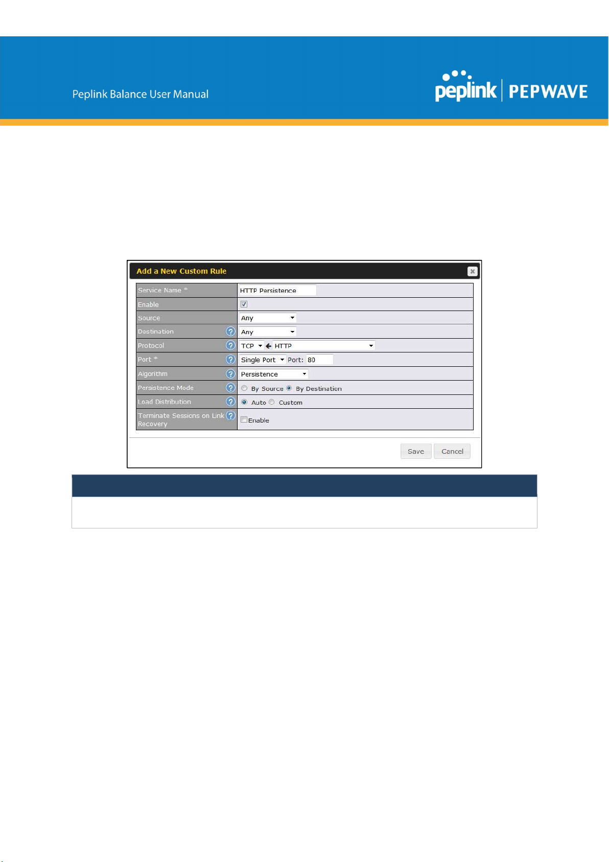
higher application compatibility but may inhibit the load balancing function unless there
are many clients using the Internet.
Settings
Set persistence in at Advanced>Outbound Policy.
Click Add Rule, select HTTP (TCP port 80) for web service, and select Persistence.
Click Save and then Apply Changes, located at the top right corner, to complete the
process.
Tip
A network administrator can use the traceroute utility to manually analyze the connection path of a particular WAN
connection.
Bypassing the Firewall to Access Hosts on LAN
Scenario
There are times when remote access to computers on the LAN is desirable; for
example, when hosting web sites, online businesses, FTP download and upload areas,
etc. In such cases, it may be appropriate to create an inbound NAT mapping for the
network to allow some hosts on the LAN to be accessible from outside of the firewall.
Solution
The web admin interface can be used to add an inbound NAT mapping to a host and to
https://www.peplink.com 187 Copyright @ 2019 Peplink
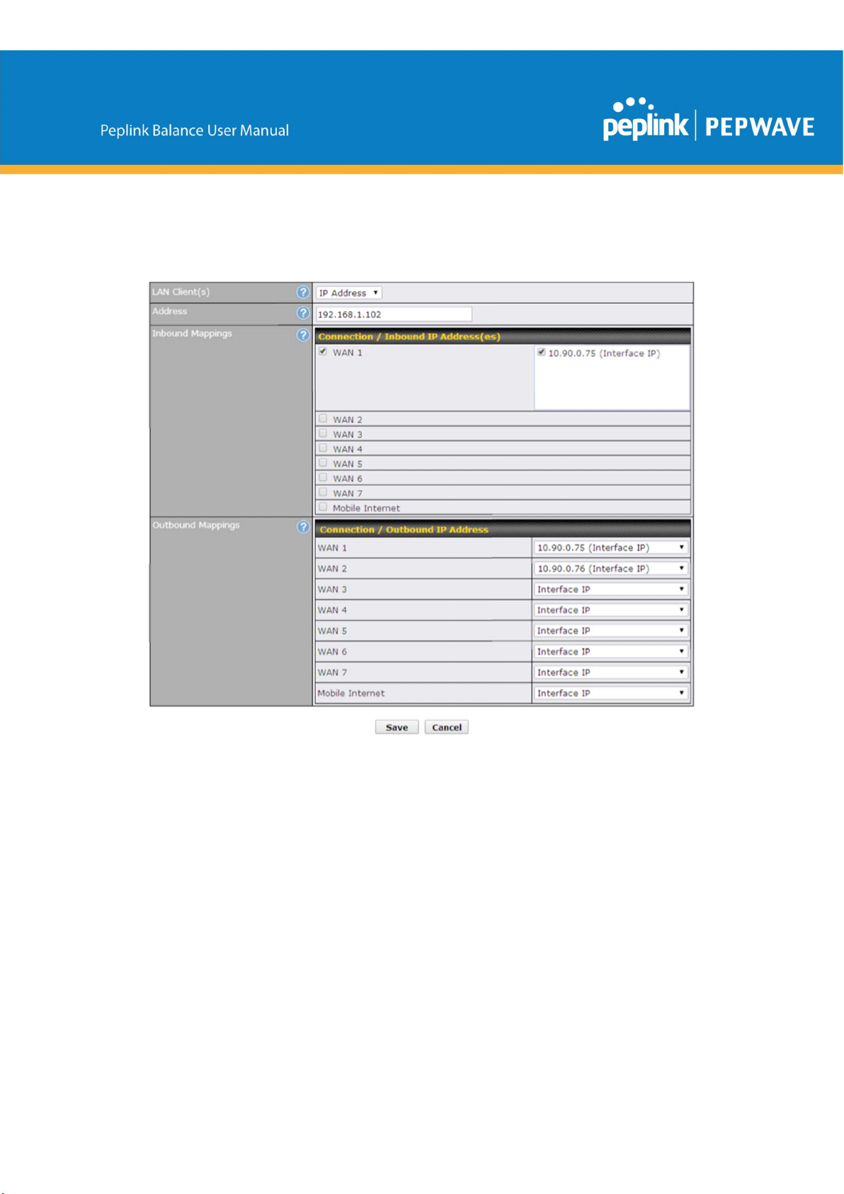
bind the host to the WAN connection(s) of your choice. To begin, navigate to
Network>NAT Mappings.
In this example, the host with an IP address of 192.168.1.102 is bound to 10.90.0.75 of
WAN1:
Click Save and then Apply Changes, located at the top right corner, to complete the
process.
Inbound Access Restriction
Scenario
A firewall is required in order to protect the network from potential hacker attacks and
other Internet security threats.
Solution
Firewall functionality is built into the Peplink Balance. By default, inbound access is
https://www.peplink.com 188 Copyright @ 2019 Peplink
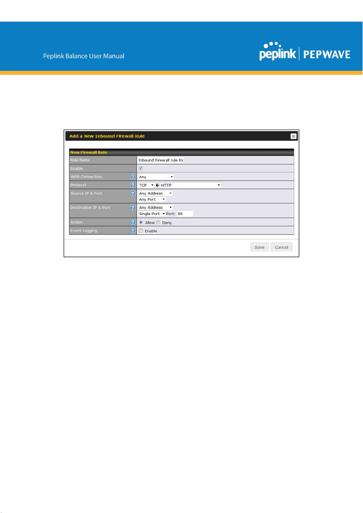
unrestricted. Enabling a basic level of protection involves setting up firewall rules.
For example, in order to protect your private network from external access, you can set
up a firewall rule between the Internet and your private network. To do so, navigate to
Advanced>Firewall>Access Rules. Then click the Add Rule button in the Inbound
Firewall Rules table and change the settings according to the following screenshot:
After the fields have been entered as in the screenshot, click Save to add the rule.
Afterwards, change the default inbound rule to Deny by clicking the default rule in the
Inbound Firewall Rules table. Click Apply Changes on the top right corner to
complete the process.
Outbound Access Restriction
Scenario
For security reasons, it may be appropriate to restrict outbound access. For example,
you may want to prevent LAN users from using ftp to transfer files to and from the
Internet. This can easily be achieved by setting up an outbound firewall rule with the
Peplink Balance.
Solution
To setup a firewall between Internet and private network for outbound access, navigate
to Advanced>Firewall>Access Rules. Click the Add Rule button in the Outbound
Firewall Rules table, and then adjust settings according the screenshot:
https://www.peplink.com 189 Copyright @ 2019 Peplink

After the fields have been entered as in the screenshot, click Save to add the rule. Click
Apply Changes on the top right corner to complete the process.
https://www.peplink.com 190 Copyright @ 2019 Peplink

Appendix D. Troubleshooting
Problem 1
Outbound load is only distributed over one WAN connection.
Solution
Outbound load balancing can only be distribute traffic evenly between available WAN
connections if many outbound connections are made. If there is only one user on the
LAN and only one download session is made from his/her browser, the WAN
connections cannot be fully utilized.
For a single user, download management applications are recommended. The
applications can split a file into pieces and download the pieces simultaneously.
Examples include: DownThemAll (Firefox Extension), iGetter (Mac), etc.
If the outbound traffic is going across the SpeedFusionTM tunnel, (i.e., transferring a file
to a VPN peer) the bandwidth of all WAN connections will be bonded. In this case, all
bandwidth will be utilized and a file will be transferred across all available WAN
connections.
For additional details, please refer to this FAQ:
http://www.peplink.com/knowledgebase/maximizing-your-wan-connections-without-
speedfusion/
Problem 2
I am using a download manager program (e.g., Download Accelerator Plus,
DownThemAll, etc.). Why is the download speed still only that of a single link?
Solution
First, check whether all WAN connections are up. Second, ensure your download
manager application has split the file into 3 parts or more. It is also possible that all of 2
or even 3 download sessions were being distributed to the same link by chance.
Problem 3
I am using some websites to look up my public IP address, e.g., www.whatismyip.com.
When I press the browser's Refresh button, the server almost always returns the same
address. Isn’t the IP address supposed to be changing for every refresh?
Solution
The web server has enabled the Keep Alive function, which ensures that you use the
same TCP session to query the server. Try to test with a website that does not enable
https://www.peplink.com 191 Copyright @ 2019 Peplink

Keep Alive.
For example, try http://private.dnsstuff.com/tools/aboutyou.ch. (This third-party web site
is provided only for reference. Peplink has no association with the site and does not
guarantee the site's validity or availability.)
Problem 4
What can I do if I suspect a problem on my LAN connection?
Solution
You can test the LAN connection using ping. For example, if you are using
DOS/Windows, at the command prompt, type ping 192.168.1.1. This pings the Peplink
Balance device (provided that Peplink Balance’s IP is 192.168.1.1) to test whether the
connection to the Peplink Balance is OK.
Problem 5
What can I do if I suspect a problem on my Internet/WAN connection?
Solution
You can test the WAN connection using ping, as in the solution to Problem 4. As we
want to isolate the problems from the LAN, ping will be performed from the Peplink
Balance. By using Ping/Traceroute under the Status tab of the Peplink Balance, you
may able to find the source of problem.
Problem 6
When I upload files to a server via FTP, the transfer stalls after a few kilobytes of data
are sent. What should I do?
Solution
The maximum transmission unit (MTU) or MSS setting may need to be adjusted. By
default, the MTU is set at 1440. Choose Auto for all of your WAN connections. If that
does not solve the problem, you can try the MTU 1492 if a connection is DSL. If
problem still persists, change the size to progressive smaller values until your problem
is resolved (e.g., 1462, 1440, 1420, 1400, etc).
Additional troubleshooting resources:
Peplink Community Forums: https://forum.peplink.com/
Appendix E. Declaration
https://www.peplink.com 192 Copyright @ 2019 Peplink

CAUTION:
RISK OF EXPLOSION IF BATTERY IS REPLACED BY AN INCORRECT TYPE.
DISPOSE OF USED BATTERIES ACCORDING TO THE INSTRUCTIONS
Federal Communication Commission Interference Statement
This equipment has been tested and found to comply with the limits for a Class A digital
device, pursuant to part 15 of the FCC Rules. These limits are designed to provide
reasonable protection against harmful interference when the equipment is operated in a
commercial environment. This equipment generates, uses, and can radiate radio
frequency energy and, if not installed and used in accordance with the instruction
manual, may cause harmful interference to radio communications. Operation of this
equipment in a residential area is likely to cause harmful interference in which case the
user will be required to correct the interference at his own expense.
FCC Caution: Any changes or modifications not expressly approved by the party
responsible for compliance could void the user's authority to operate this equipment.
This transmitter must not be co-located or operating in conjunction with any other
antenna or transmitter.
Operations in the 5.15-5.25GHz band are restricted to indoor usage only.
Radiation Exposure Statement :
This equipment complies with FCC radiation exposure limits set forth for an uncontrolled
environment. This equipment should be installed and operated with a minimum distance
of 49 cm between the radiator and your body.
Note: The country code selection is for non-US models only and is not available to all
US models. Per FCC regulation, all WiFi products marketed in US must fixed to US
operation channels only.
https://www.peplink.com 193 Copyright @ 2019 Peplink

EU Declaration of Conformity
Name of manufacturer: PISMO LABS TECHNOLOGY LIMITED
Address of the manufacturer: FLAT/RM A5 5/F HK SPINNERS IND BLDG PHASE 6, 481
CASTLE PEAK ROAD CHEUNG SHA WAN, Kowloon, Hong Kong
We affirm the electrical equipment manufactured by us fulfils the requirements of the
Radio Equipment Directive 2014/53/EU.
Description of the appliance: PEPWAVE / PEPLINK Wireless Product
Model name of the appliance: Peplink Balance 30 Pro / BPL-031-LTEA-W-T / Balance 30 Pro
/ Pismo811AC / B30 Pro
Trademark: PEPWAVE / PEPLINK
The construction of the appliance is in accordance with the following standards:
EN 300 328 V2.1.1
EN 301 893 V2.1.1
EN 301908-1 V11.1.1
EN 301 489-1 V2.2.0
EN 301 489-17 V3.2.0
EN 301 489-52 V1.1.0
EN 55032: 2015 + AC:2016
EN 61000-3-2: 2014
EN 61000-3-3: 2013
EN 55024: 2010 + A1 :2015
EN 62311 : 2008
EN 62368-1:2014/AC:2015
Hong Kong, May 7, 2019
https://www.peplink.com 194 Copyright @ 2019 Peplink

with the essential requirements and other relevant provisions of Directive 1999/5/EC.
cumple
ΔΙΑΤΑΞΕΙΣ ΤΗΣ ΟΔΗΓΙΑΣ 1999/5/ΕΚ.
Operations in the 5.15-5.35GHz band are restricted to indoor usage only.
Česky
[Czech]
[Jméno výrobce] tímto prohlašuje, že tento [typ zařízení] je ve shodě se základními
požadavky a dalšími příslušnými ustanoveními směrnice 1999/5/ES.
Dansk
[Danish]
Deutsch
[German]
Eesti
[Estonian]
English Hereby, [name of manufacturer], declares that this [type of equipment] is in compliance
Español
[Spanish]
Ελληνική
[Greek]
Français
[French]
Undertegnede [fabrikantens navn] erklærer herved, at følgende udstyr [udstyrets
typebetegnelse] overholder de væsentlige krav og øvrige relevante krav i direktiv
1999/5/EF.
Hiermit erklärt [Name des Herstellers], dass sich das Gerät [Gerätetyp] in
Übereinstimmung mit den grundlegenden Anforderungen und den übrigen einschlägigen
Bestimmungen der Richtlinie 1999/5/EG befindet.
Käesolevaga kinnitab [tootja nimi = name of manufacturer] seadme [seadme tüüp = type
of equipment] vastavust direktiivi 1999/5/EÜ põhinõuetele ja nimetatud direktiivist
tulenevatele teistele asjakohastele sätetele.
Por medio de la presente [nombre del fabricante] declara que el [clase de equipo]
con los requisitos esenciales y cualesquiera otras disposiciones aplicables o exigibles de
la Directiva 1999/5/CE.
ΜΕ ΤΗΝ ΠΑΡΟΥΣΑ [name of manufacturer] ΔΗΛΩΝΕΙ ΟΤΙ [type of equipment]
ΣΥΜΜΟΡΦΩΝΕΤΑΙ ΠΡΟΣ ΤΙΣ ΟΥΣΙΩΔΕΙΣ ΑΠΑΙΤΗΣΕΙΣ ΚΑΙ ΤΙΣ ΛΟΙΠΕΣ ΣΧΕΤΙΚΕΣ
Par la présente [nom du fabricant] déclare que l'appareil [type d'appareil] est conforme
aux exigences essentielles et aux autres dispositions pertinentes de la directive
1999/5/CE.
https://www.peplink.com 195 Copyright @ 2019 Peplink

Ar šo
99/5/EK būtiskajām prasībām un citiem ar to saistītajiem
Alulírott,
v skladu z bistvenimi zahtevami in ostalimi
Italiano
[Italian]
Con la presente [nome del costruttore] dichiara che questo [tipo di apparecchio] è
conforme ai requisiti essenziali ed alle altre disposizioni pertinenti stabilite dalla direttiva
1999/5/CE.
Latviski
[Latvian]
Lietuvių
[Lithuanian]
Nederlands
[Dutch]
Malti
[Maltese]
Magyar
[Hungarian]
Polski
[Polish]
Português
[Portuguese]
Slovensko
[Slovenian]
Slovensky
[Slovak]
[name of manufacturer / izgatavotāja nosaukums] deklarē, ka [type of equipment /
iekārtas tips] atbilst Direktīvas 19
noteikumiem.
Šiuo [manufacturer name] deklaruoja, kad šis [equipment type] atitinka esminius
reikalavimus ir kitas 1999/5/EB Direktyvos nuostatas.
Hierbij verklaart [naam van de fabrikant] dat het toestel [type van toestel] in
overeenstemming is met de essentiële eisen en de andere relevante bepalingen van
richtlijn 1999/5/EG.
Hawnhekk, [isem tal-manifattur], jiddikjara li dan [il-mudel tal-prodott] jikkonforma mal-
ħtiġijiet essenzjali u ma provvedimenti oħrajn relevanti li hemm fid-Dirrettiva 1999/5/EC.
[gyártó neve] nyilatkozom, hogy a [... típus]megfelel a vonatkozó alapvetõ
követelményeknek és az 1999/5/EC irányelv egyéb elõírásainak.
Niniejszym [nazwa producenta] oświadcza, że [nazwa wyrobu] jest zgodny z
zasadniczymi wymogami oraz pozostałymi stosownymi postanowieniami Dyrektywy
1999/5/EC.
[Nome do fabricante] declara que este [tipo de equipamento] está conforme com os
requisitos essenciais e outras disposições da Directiva 1999/5/CE.
[Ime proizvajalca] izjavlja, da je ta [tip opreme]
relevantnimi določili direktive 1999/5/ES.
[Meno výrobcu] týmto vyhlasuje, že [typ zariadenia]spĺňa základné požiadavky a všetky
príslušné ustanovenia Smernice 1999/5/ES.
Suomi
[Finnish]
Svenska
[Swedish]
[Valmistaja = manufacturer] vakuuttaa täten että [type of equipment = laitteen
tyyppimerkintä] tyyppinen laite on direktiivin 1999/5/EY oleellisten vaatimusten ja sitä
koskevien direktiivin muiden ehtojen mukainen.
Härmed intygar [företag] att denna [utrustningstyp] står I överensstämmelse med de
väsentliga egenskapskrav och övriga relevanta bestämmelser som framgår av direktiv
1999/5/EG.
https://www.peplink.com 196 Copyright @ 2019 Peplink
 Loading...