


User Manual
Pismolabs 101 mini
October 09
COPYRIGHT & TRADEMARKS
Specifications are subjec t to change w itho ut notice. Copyright © 20 09 Pepwave Ltd. All Rights Reserved. Pepwave
and the Pepwave logo are trademarks of Pepwave Ltd. Other brands o r produc ts mentioned may be tr ademarks or
registered trademarks of their respective owners.

Pismolabs 101 mini User Manual
Table of Contents
1 COPYRIGHT ..................................................................................................................................... 3
2 DISCLAIMER ..................................................................................................................................... 3
3 PRODUCT DESCRIPTION ................................................................................................................. 4
3.1 PRODUCT FEATURES ..................................................................................................................... 4
3.2 HARDWARE SETUP ........................................................................................................................ 5
3.3 LED DESCRIPTION ........................................................................................................................ 6
4 USING THE PEPWAVE DEVICES ....................................................................................................... 7
4.1 PRE-CONFIGURING PC SETUP ....................................................................................................... 7
4.2 FIRST TIME SETUP ........................................................................................................................... 8
4.3 SETTINGS DETAILS ....................................................................................................................... 12
4.4 INTEGRATED WI-FI ACCESS POINT CONFIGURATION .................................................................... 17
4.5 TEST THE SETUP ............................................................................................................................ 20
4.6 PORT FORWARDING ................................................................................................................... 21
4.7 QOS ......................................................................................................................................... 23
4.8 FIRMWARE UPGRADE ................................................................................................................. 24
4.9 DEBUG AND SYSTEM INFORMATION ............................................................................................. 25
4.10 RESTORE TO DEFAULT SETTINGS .................................................................................................... 26
APPENDIX: .......................................................................................................................................... 27
FEDERAL COMMUNICATION COMMISSION INTERFERENCE STATEMENT ............................................... 27
Pismolabs 101 mini
- 2 -
Copyright © 2009 Pepwave

Pismolabs 101 mini User Manual
1 Copyright
Copyright © 2009 by Pepwave Ltd.
The content of this documentation may not be re produced in any part or as a whole without
the prior written permission of Pepwave Ltd.
2 Disclaimer
Pepwave does not assume any liability arising out of the application or use of any products,
or software described herein. Neither does it convey any license under its patent right nor
the patent rights of others. Pepwave further reserves the right to make changes in any
products described herein without notice. This documentation is subject to change without
notice.
Pismolabs 101 mini
- 3 -
Copyright © 2009 Pepwave

Pismolabs 101 mini User Manual
3 Product Description
3.1 Product Features
Signal strength LED for showing the current signal strength
Always-on, integrated Wi-Fi access point (Pismolabs 101 mini AP Series)
WPA/WPA2-Personal and WPA/WPA2-Enterprise security support
Wi-Fi Multimedia (WMM) support
Built-in DHCP server and NAT routing to manage client devices
Customizable, built-in web portal for simple web-based configuration
Pismolabs 101 mini
- 4 -
Copyright © 2009 Pepwave

Pismolabs 101 mini User Manual
3.2 Hardware Setup
3.2.1 Pismolabs 101 mini
1. Attach the provided antenna to the left most antenna connector
2. Connect the LAN port to the computer’s Ethernet port with an Ethe rnet cable.
3. Connect the end of the included power adapter to the power socket on Pismolabs
101 mini.
4. Power on the power adaptor.
Pismolabs 101 mini
- 5 -
Copyright © 2009 Pepwave

Pismolabs 101 mini User Manual
3.3 LED Description
3.3.1 Pismolabs 101 mini
LED Color Status Description
PWR
RDY
ENET
Wi-Fi
Signal
Bars
Green On Power is on
Off Power is off
Green Solid
Green Blinking Received signal is Low
Amber Blinking Received signal is Very Low
Amber Solid No wireless signal is detected
Off Booting up / Upgrading firmware
Green On Ethernet is connected
Green Blinking Sending/Receiving data
Off Ethernet is not connected
Green On Associated with an access point
Blinking Sending/Receiving data
Off Not associated with any access point
Green N/A
Received signal is Excellent, Very Good and
Good
The number of lit signal bars depends on the
strength of the received signal. A larger
number of lit signal bars indicate stronger
signals.
Pismolabs 101 mini
- 6 -
Copyright © 2009 Pepwave

Pismolabs 101 mini User Manual
4 Using the Pepwave Devices
4.1 Pre-configuring PC Setup
You should set up your computer’s LAN interfa ce to obtain an IP address automatically. If
you do so, you should hav e set it up correctly.
In order to do so, select the Start menu, Control Panel and then Network Connections.
Right click on the Local Area Connection icon, choose Properties, and double-click on
the item Internet Protocol (TCP/IP) from the list. On the screen, just set it as follows:
Click the OK button to confirm the change.
Pismolabs 101 mini
- 7 -
Copyright © 2009 Pepwave

Pismolabs 101 mini User Manual
4.2 First Time Setup
On your PC, start a web browser, e.g. Internet Explorer, Mozilla Firefox, etc. Visit an
Internet web site. If you are not associated to an access point, you should be redirected to
a logon page. Or you can go also go to this URL
http://192.168.20.1/
The page will look like this.
Illustration 1: Welcome Page
Pismolabs 101 mini
- 8 -
Copyright © 2009 Pepwave

Pismolabs 101 mini User Manual
Click the Advanced Config button to enter the parameters of the access point to associate
to. You should see this screen:
Illustration 2: Pismolabs 101 mini AP Setup Page
Pismolabs 101 mini
- 9 -
Copyright © 2009 Pepwave

Pismolabs 101 mini User Manual
In the field SSID under Wireless Settings, input the access point’s SSID (sometimes it is
called the “network name”). According to the setting of the Access Point you are
associating to, you may choose a different Authentication setting.
If Static WEP key or WPA/WPA2-Personal is selected for Authentication, input the
Encryption Key field as well. (There are also options of 802.1x with dynamic WEP key
and WPA/WPA2-Enterprise. You do not need to use these settings unless instructed to
do so by your ISP.)
Click the Save button at the bottom to complete.
You can now click the Connect link on the top bar and then click the Connect button to
associate with the access point.
Pismolabs 101 mini
- 10 -
Copyright © 2009 Pepwave
Pismolabs 101 mini User Manual
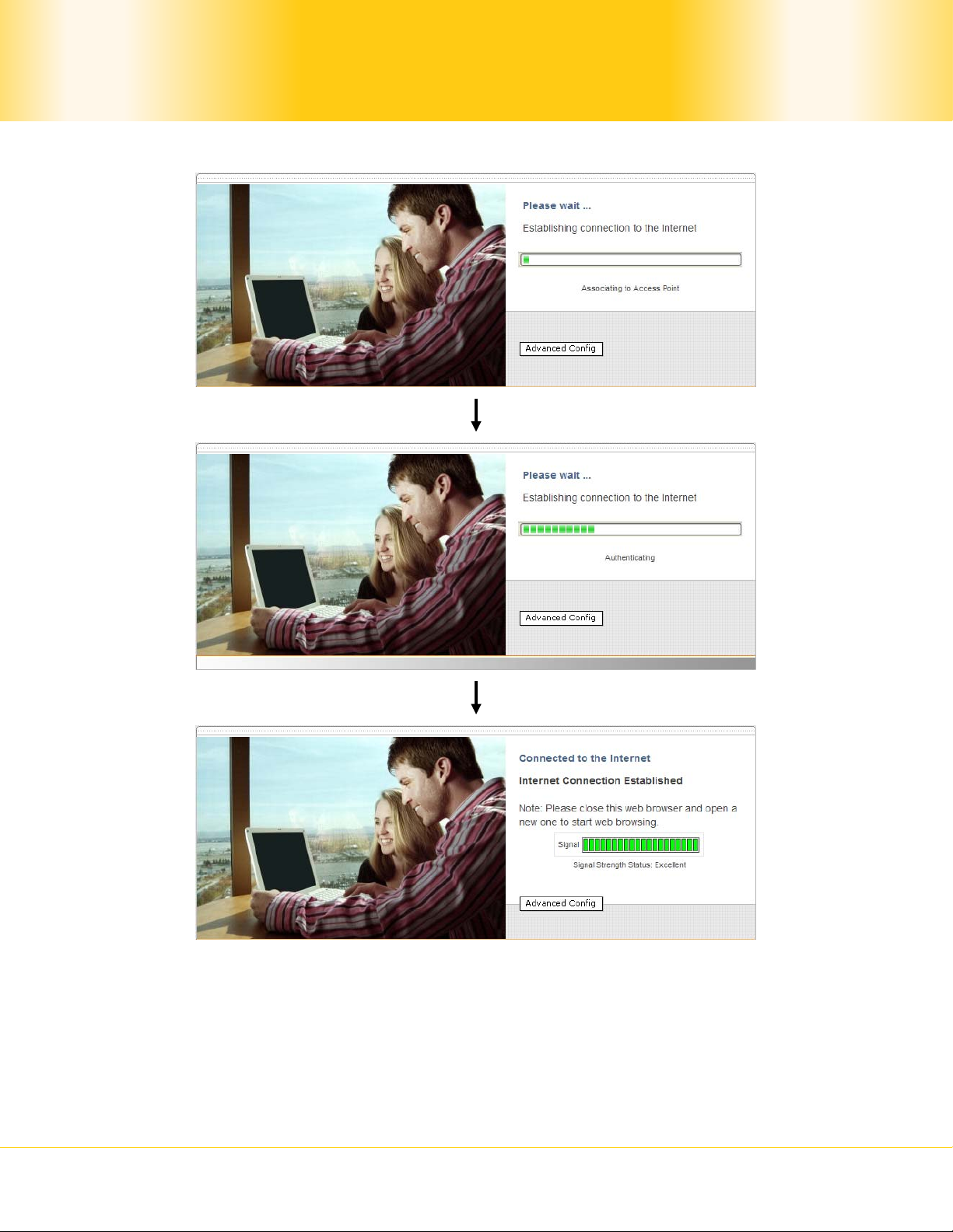
Illustration 3: Establishing Connection to the Internet
At this point, you are associated with the access point. You may now close the web browser
and open a new one to start web browsing.
Pismolabs 101 mini
- 11 -
Copyright © 2009 Pepwave

Pismolabs 101 mini User Manual
4.3 Settings Details
4.3.1 IP Settings
Illustration 4: IP Settings
LAN
Interface
DHCP
Server
IP Settings
To configure the LAN interface’s IP address and subnet mask.
(Applicable to Pismolabs 101 mini AP Series)
To configure and enable the built-in DHCP server or not. If enabled, the IP
address range can be configured. Configure DHCP Reservation if there is a
need to assign a specific IP address to a specific MAC address using DHCP.
Pismolabs 101 mini
- 12 -
Copyright © 2009 Pepwave

Pismolabs 101 mini User Manual
4.3.2 Wireless Settings
SSID
Radio Mode
Channel
Scanning Mode
Bit Rate
Authentication
Illustration 5: Wireless Setti n g s
Wireless Setting s
To configure the SSID / ESSID / Network Name of the wireless network
to associate to.
It allows the user to choose between radio modulations support. E.g.
802.11b/g, 802.11g only, 802.11b, etc. The available settings depend
on the Wi-Fi module installed on the device.
To select different channels that preferred to scan.
To fix the 802.11 transmit bit rate. Available options d epend on the
Radio Mode chosen. If auto is chosen, the device will choose the best
bit rate dynamically and automatically.
Available options are Open, Static WEP Key, 802.1x with dynamic WEP
key, WPA/WPA2-Enterprise and WPA/WPA2-Personal. The selection
should be according to the setting of the acces s point you are
associating to. Data transferred are encrypted under all modes except
in Open mode. When Static WEP Key or WPA/WPA2-Personal is chosen,
you should enter an e ncryption key in the Encryptio n Key field. You do
not need to use 802.1x and WPA/WPA2-Enterprise unless instructed to
do so by your ISP.
The MAC address of a preferred access point can be entered here.
When the preferred access point is found and its signal strength is
Preferred AP
higher than the Min Signal Strength, it will connect to this preferred
access point, no matter the other access points are found even they
have higher signal strength or the same SSID.
Pismolabs 101 mini
- 13 -
Copyright © 2009 Pepwave
Pismolabs 101 mini User Manual
4.3.3 Roaming Settings for Pismolabs 101 mini:
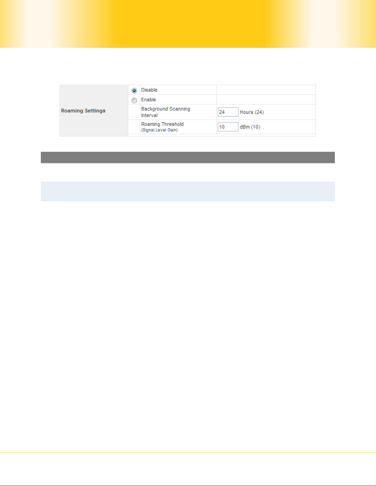
Illustration 6: Roaming Settings
Roaming Settings
Roaming Settings
Background
Scanning Interval
Roaming
Threshold (Signal
Level Gain)
To configure and enable roaming among APs w ith the same SSID and
authentication method.
The time interval between background scans.
If there is another AP with a signal level greater than the signal level
of connected AP by the specified value, it will reconnect to the AP
with better signal.
Pismolabs 101 mini
- 14 -
Copyright © 2009 Pepwave

Pismolabs 101 mini User Manual
4.3.4 Wireless IP Settings
IP Settings
MTU Size
AP Settings
Pismolabs 101 mini
Illustration 7: Wireless IP Settings
Wireless IP Settings
The IP address can be obtained automatically or configured manually.
If you choose to manua lly configure the IP address for your unit,
enter the fields IP Address, Subnet Mask, Default Gateway, Preferred
DNS Server and Alternate DNS Server.
You may also set the MTU Size to increase the data packet size your
unit can handle at on e time.
(Applicable to Pismolabs 101 mini AP Series)
The AP Settings will be covered in detail in the subsequent section
Integrated Wi-Fi Access Point Configuration.
- 15 -
Copyright © 2009 Pepwave

Pismolabs 101 mini User Manual
4.3.5 Restore and Reboot
Illustration 8: Restore and Reboot
Restore and Reboot
If the device is not connected to an access point, and the user is
accessing an Internet web site, the settings control whether to
redirect the web access to the web admin interface page or not. If
WAI Redirection
this is disabled and the device is not connec ted, the browser will show
a web access error message. The user can still access the web admin
interface by accessing to the device’s LAN IP address. By default, the
LAN IP address is set as http://192.168.20.1.
Web Password
Protection
Restore Factory
Settings
Sets the password to protect the web user interface.
To restore the device to default settings. When this option is clicked,
default settings will be restored and the unit will be restarted.
Reboot CPE To restart the device.
Pismolabs 101 mini
- 16 -
Copyright © 2009 Pepwave

Pismolabs 101 mini User Manual
4.4 Integrated Wi-Fi Access Point Configuration
Integrated Wi-Fi Access Point is configured via the CPE Setup tab. The following sections
will provide information as a guide thro ugh the configuration.
The available Access Point (AP) settings for the Integrated Wi-Fi Access Point functionality
are as follows:
Disable
Integrated Wi-Fi Access Point functionality is disabled.
Configure Manually
Manual configuration of the SSID, Authent ication, and Encryption Key values
corresponding to the Access Point.
Configure Automatically
The SSID, Authentication, and Encryption Key values corresponding to t he Access
Point are automatically configured to be the same as the respective values that
correspond to the ISP’s network.
4.4.1 Access Point Disabled
Illustration 9: Access Point Disabled
Pismolabs 101 mini
- 17 -
Copyright © 2009 Pepwave

Pismolabs 101 mini User Manual
4.4.2 Access Point configure Manually
Illustration 10: Access Point Configure Manually
Configure Manually
AP SSID In Manual Configuratio n mode, the SSID is manually entered.
It can be one of three configurable values:
• Open
No Encryption Key is necessary.
Authentication
• Static WEP Key
A 64- or 128-bit Encryption Key is required, and can be
entered in either an ASCII or HEX representation.
• WPA/WPA2-Personal
An Encryption Key, of at least 8 characters, is required.
Pismolabs 101 mini
- 18 -
Copyright © 2009 Pepwave

Pismolabs 101 mini User Manual
4.4.3 Access Point Configure Automatically
Illustration 11: Access Point Configure Automatically
AP Settings
With this option enabled, the configured SSID will be broadcast such
that it can be detected by an SSID scan. Otherwise, t he configured
Broadcast SSID
SSID will not be broadcast such that it cannot be detected by an
SSID scan. In order to connect with the access point, the SSID
needs to be known by the client.
Client Isolatio n
Keep AP
AP Transmit
Power
Adjustment
Prevent wireless clients connected to the AP from communicating with
each other.
With this option enabled, the Wi-Fi Access Point will always on even if
there is no connec t io n to t h e mesh network.
An option to retain a lower power setting for indoor home devices.
Available options are between -1 dBm and –15dBm.
With the Access Point Configuration set to Conf ig ure Automatically, the SSID,
Authentication, and Encryption Key values of the Integrated Wi-Fi Access Point will be
configured to be the same as in the 4.3.2 Wireless IP Settings section.
This configuration mode is effectively equivalent to directly connecting 802.1b/g devices on
the customers’ premises with Citywide Wi-Fi.
Important Note
In the Wireless Settings section, if Authentication is se t t o either 802.1x with dynamic
WEP key or WPA/WPA2-Enterprise, then the Configure Automatically option of the
Access Point Configuration becomes unava i lable, because the Integrated Wi-Fi Access
Point functionality currently does not support authentication via the 802.1x with dynamic
WEP key and WPA/WPA2-Enterprise methods.
Pismolabs 101 mini
- 19 -
Copyright © 2009 Pepwave

Pismolabs 101 mini User Manual
4.5 Test the Setup
To test the setup, you can now go to the unit’s main page, enter the user name and
password. The realm (the text box next to the “@” sign) value can be left empty. Then
click the Connect button.
Illustration 12: Establishing Connection to the Internet
After connected, you should see:
Illustration 13: Internet Connec t i on Established
Pismolabs 101 mini
- 20 -
Copyright © 2009 Pepwave

Pismolabs 101 mini User Manual
4.6 Port Forwarding
The Pismolabs devices can forward traffic from different port(s) to a specific IP address.
Port Forwarding Settings
Service Port
Range
Protocol
IP Address The IP address that you would like the traffics forwarded to.
Del
Enter a port or a range of ports that would like to forward.
The Protocol for the above port(s) forwarding. You should select at
least one protocol between TCP and UDP.
By clicking the button, you can delete the corresponding rows of port
forwarding rules.
Pismolabs 101 mini
- 21 -
Copyright © 2009 Pepwave

Pismolabs 101 mini User Manual
Below the port forwarding table is an option called DMZ Host. If you Enable this function,
you can manually ente r an IP address, which will be the IP address of the device that
expose to th e In t e rn et. The purpose of a DMZ is adding an additional layer of security to
your LAN, which may make all external users can only has access to the device in the DMZ,
rather than the whole of the network.
Tip
Below is a table showing some well-known ports, which is officially registered with IANA.
Port Number Description Protocol
7 Echo TCP, UDP
21 FTP TCP
23 TELNET TCP
25 SMTP TCP, UDP
53 DNS TCP, UDP
79 Finger TCP
80 HTTP TCP, UDP
110 POP3 TCP
119 NNTP TCP
161 SNMP TCP, UDP
162 SNMP Trap TCP, UDP
Pismolabs 101 mini
- 22 -
Copyright © 2009 Pepwave
Pismolabs 101 mini User Manual
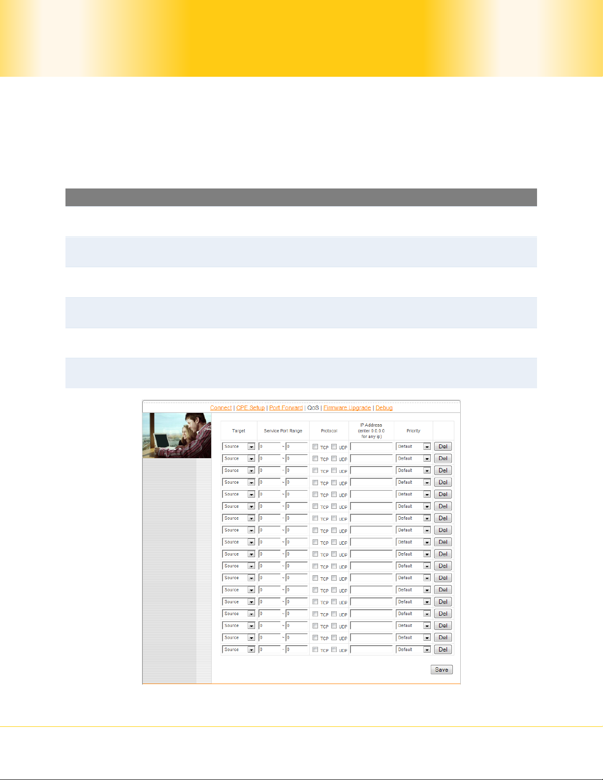
4.7 QoS
QoS, in long is Quality of Service, refers to resource reservation control mechanisms. By
custom this option, you may select a specific traffic from a source or to a target to have
higher priority than the others, thus to have a higher and better performance than the
others.
QoS Settings
Target
Service Port
Range
Protocol
IP Address
Priority
Del
To choose whether it is an incoming (Source) or outgoing
(Destination) traffic that should be controlled by the service.
Enter a port or a range of ports that would like to be controlled by the
service.
The Protocol for the above port(s). You should select at least one
protocol between TCP and UDP.
The IP address that you would like the traf fics to be controlled by the
service.
There are three choices for service priority: B ac k grou nd, Video and
Voice. By choosi n g Default, priority will be automatically adjusted.
By clicking the button, you can delete the corresponding rows of port
forwarding rules.
Pismolabs 101 mini
- 23 -
Copyright © 2009 Pepwave

Pismolabs 101 mini User Manual
4.8 Firmware Upgrade
The Pepwave devices are able to check whether a newer firmware (the soft ware running on
the unit) is available.
However, it is recommended that you do not update the firmware unless specifically
instructed by your ISP to do so. When a firmware upgrade is needed, your ISP will either
give you instructions or upgrade the firmware remotely.
Illustration 14: Firmware tab showing the system information
It is highly recommended users to download the c onfiguration file (download directory
can be found in the next section) for backup propose before doing firmware upgrade.
Pismolabs 101 mini
Tip
- 24 -
Copyright © 2009 Pepwave

Pismolabs 101 mini User Manual
4.9 Debug and System information
Illustration 15: Debug tab showi ng t he system information
Debug dump and configuration file can be downloaded through cl icking the links
illustrated above. If you encounter issues and would like to contact Technical Support
Team, please download the above files and attach it along with a de scription of your
encountered issue.
Pismolabs 101 mini
Tip
- 25 -
Copyright © 2009 Pepwave

Pismolabs 101 mini User Manual
Reset
4.10 Restore to Default Settings
4.10.1 Pismolabs 101 mini Indoor Series
There are two ways to restore the Pismolabs 101 mini Indoor unit to default settings.
If you are able to access the web admin interface, go to the CPE Setup page, and click the
Restore and Reboot button.
Otherwise, you can also power up the unit and wait for about 1 min. Then press the Reset
Button at the rear side of the unit using a pin and then hold it for 5 seconds. The unit will
restore the settings to factory default and reboot.
Button
Pismolabs 101 mini
- 26 -
Copyright © 2009 Pepwave

Pismolabs 101 mini User Manual
Appendix:
Federal Communication Commission Interference Statement
This equipment has been tested and found to comply with the limits for a Class B digital
device, pursuant to Part 15 of the FCC Rules. These limits are designed to provide
reasonable protection against harmful interference in a residential installation. This
equipment generat es, uses and c an radi ate rad io frequ ency energy and, i f not i nstall ed and
used in accordance with the instructions, may cause harmful interference to radio
communications. However, there is no guarantee that interference will not occur in a
particular installation. If this equipment does cause harmful interference to radio or
television rec ep t ion, which can b e determined by tu rning the equipment off and on, the user
is encouraged to try to correct the interference by one of the following measures:
1) Reorient or relocate the receiving antenna.
2) Increase the separation between the equipment and receiver.
3) Connect the equipment into an outlet on a circuit different from that to which the
receiver is connected.
4) Consult the dealer or an experienced radio/TV technician for help.
This device complies with Part 15 of the FCC Rules. Operation is subject to the following two
conditions: (1) This device may not cause harmful interference, and (2) this device must
accept any in terf eren c e re ceiv ed, in cl udi ng i nt erfe renc e t hat may cau se u ndesi red ope rati on .
FCC Caution: Any changes or modifications not expressly approved by the party responsible
for compliance could void the user's authority to operate this equipment.
IMPORTANT NOTE
FCC Radiation Exposure Statement
This equipment complies with FCC radiation ex posure limits set forth for an uncontrolled
environment. This equipment should be installed and operated with minimum distance 20cm
between the radiator & your body.
This transmitter must not be co-located or operating in conjunction with any other antenna
or transmitter.
Pismolabs 101 mini
- 27 -
Copyright © 2009 Pepwave

Contact Us:
Sales
sales@pepwave.com
Support
support@pepwave.com
Business Development and
Partnerships
partners@pepwave.com
www.pepwave.com
Address:
United States Office
800 West El Camino Real,
Mountain View
CA 94040
United States
Tel: +1 (650) 331 0641
Fax: +1 (650) 625 4664
Hong Kong Office
17/F, Park Building,
476 Castle Peak Road
Cheung Sha Wan
Hong Kong
Tel: +852 2990 7600
Fax: +852 3007 0588
Hong Kong Office
17/F, Park Building,
476 Castle Peak Road
Cheung Sha Wan
Hong Kong
Tel: +852 2990 7600
Fax: +852 3007 0588
 Loading...