


FCC ID: XRN-MAX600
User Manual
Mobile Router
Document Rev. 1.0
June 09
COPYRIGHT & TRADEMARKS
Specifications are subject to change without notice. Copyright © 2009 Pepwave Ltd. All Rights Reserved. Pepwave
and the Pepwave logo are trademarks of Pepwave Ltd. Other brands or products mentioned may be trademarks or
registered trademarks of their respective owners.

Table of Contents
1 INTRODUCTION AND SCOPE ....................................................................................................... 4
2 GLOSSARY .................................................................................................................................... 4
3 PRODUCT FEATURES...................................................................................................................... 5
3.1 SUPPORTED NETWORK FEATURES ................................................................................................. 5
3.2 OTHER SUPPORTED FEATURES ..................................................................................................... 5
4 PACKAGE CONTENT .................................................................................................................... 6
5 PEPWAVE MAX MOBILE ROUTER OVERVIEW ............................................................................... 7
5.1 FRONT PANEL APPEARANCE ...................................................................................................... 7
5.2 LED INDICATORS ...................................................................................................................... 7
5.3 REAR PANEL APPEARANCE ........................................................................................................ 8
5.4 UNIT BASE APPEARANCE ........................................................................................................... 8
6 INSTALLATION ............................................................................................................................... 9
6.1 CONNECTING THE NETWORK WITH PEPWAVE MAX MOBILE ROUTER ............................................. 9
6.2 CONFIGURING COMPUTERS ON THE LAN ................................................................................. 12
7 CONNECTING TO WEB ADMIN INTERFACE ............................................................................... 15
8 CONFIGURATION OF LAN INTERFACE(S) .................................................................................. 16
8.1 BASIC SETTINGS ....................................................................................................................... 16
8.2 WI-FI AP................................................................................................................................ 18
9 CONFIGURATION OF WAN INTERFACE(S) ................................................................................. 20
9.1 ETHERNET WAN ...................................................................................................................... 20
9.2 EXPRESS CARD / PC CARD / USB1 / USB2 ............................................................................. 28
9.3 WI-FI WAN ........................................................................................................................... 29
10 ADVANCED WI-FI SETTINGS ....................................................................................................... 31
11 SITE-TO-SITE VPN .............................................................................................................. .......... 33
11.1 CONFIGURATION OF SITE-TO-SITE VPN ..................................................................................... 33
11.2 PEPWAVE MAX BEHIND NAT ROUTER ...................................................................................... 35
11.3 VPN STATUS ........................................................................................................................... 35
12 OUTBOUND POLICY .................................................................................................................... 36
12.1 CUSTOM RULES FOR OUTBOUND TRAFFIC MANAGEMENT ........................................................... 37
13 SERVICE FORWARDING .............................................................................................................. 43
13.1 SMTP FORWARDING ............................................................................................................... 43
13.2 WEB PROXY FORWARDING ...................................................................................................... 44
13.3 DNS FORWARDING ................................................................................................................ 44
14 PORT FORWARDING ................................................................................................................... 45
15 NAT MAPPINGS .......................................................................................................................... 48
16 FIREWALL ..................................................................................................................................... 50
16.1 OUTBOUND AND INBOUND FIREWALL ........................................................................................ 50
16.2 INTRUSION DETECTION AND DOS PREVENTION ........................................................................... 53
17 TRAFFIC PRIORITIZATION ............................................................................................................ 54
18 SERVICE PASSTHROUGH ............................................................................................................ 55
19 SYSTEM SETTINGS ........................................................................................................................ 57
19.1 ADMIN SECURITY ..................................................................................................................... 57
Pepwave MAX Mobile Router
- 2 -
Copyright © 2009 Pepwave

19.2 FIRMWARE UPGRADE .............................................................................................................. 59
19.3 TIME ....................................................................................................................................... 60
19.4 EMAIL NOTIFICATION ............................................................................................................... 61
19.5 REMOTE SYSLOG ..................................................................................................................... 62
19.6 SNMP ................................................................................................................................... 63
19.7 SAVING AND LOADING CONFIGURATIONS ................................................................................ 65
19.8 FLASH MANAGEMENT .............................................................................................................. 66
19.9 REBOOT ................................................................................................................................. 66
19.10 PING TEST .......................................................................................................................... 66
19.11 TRACEROUTE TEST ............................................................................................................... 67
20 STATUS 69
20.1 DEVICE .................................................................................................................................. 69
20.2 LINK USAGE STATUS ................................................................................................................. 70
20.3 ACTIVE SESSIONS .................................................................................................................... 71
20.4 DHCP CLIENTS ...................................................................................................................... 72
20.5 EVENT LOG ............................................................................................................................ 72
APPENDIX A. RESTORATION OF FACTORY DEFAULTS ......................................................................... 74
APPENDIX B. PRODUCT SPECIFICATIONS ........................................................................................... 75
B.1 PEPWAVE MAX MOBILE ROUTER ............................................................................................. 75
Pepwave MAX Mobile Router
- 3 -
Copyright © 2009 Pepwave

1 Introduction and Scope
The Pepwave MAX Mobile Router provides link aggregation and load balancing across six
WAN connections, allowing a combination of technologies like 3G HSDPA, EVDO, Wi-Fi,
WiMAX, and Satellite to be utilized to connect to the Internet.
This manual presents how to set up the Pepwave MAX Mobile Router and provides an
introduction to the features and usage of Pepwave MAX Mobile Router.
2 Glossary
The following terms, acronyms, and abbreviations are frequ ently used in this manual:
Term Definition
DHCP Dynamic Host Configuration Protocol
DNS Domain Name System
HTTP Hyper-Text Transfer Protocol
ICMP Internet Control Message Protocol
IP Internet Protocol
LAN Local Area Network
MAC Address Media Access Control Address
MTU Maximum Transmission Unit
MSS Maximum Segment Size
NAT Network Address Translation
PPPoE Point to Point Protocol over Ethernet
SNMP Simple Network Management Protocol
TCP Transmission Control Protocol
UDP User Datagram Protocol
VRRP Virtual Router Redundancy Protocol
WAN Wide Area Network
Pepwave MAX Mobile Router
- 4 -
Copyright © 2009 Pepwave

3 Product Features
The following is the list of supported features on Pepw ave MAX Mobile Router:
3.1 Supported Network Features
3.1.1 WAN
Multiple public IP support (DHCP, PPPoE, Static IP Address)
Ethernet WAN 10/100 Mbps Connection in Full/Half Duplex
USB WAN Connection
PC Card WAN connection
ExpressCard WAN connection
Wi-Fi WAN Connection
Network Address Translation (NAT) / Port Address Translation (PAT)
Inbound and Outbound NAT mapping
IPsec NAT-T and PPTP packet passthrough
Multiple static IP addresses per WAN Connection
MAC address clone
Customizable MTU and MSS values
WAN connection health check
Dynamic DNS (Supported service providers: changeip.com, dyndns.org, no-ip.org
and tzo.com)
3.1.2 LAN
DHCP server on LAN
St atic routing rules
3.1.3 Site-to-Site VPN
Secure yet easy to setup site-to-site VPN
3.1.4 Firewall
Outbound (LAN to WAN) firewall rules
Inbound (WAN to LAN) firewall rules per WAN connection
Intrusion detection and prevention
Specification of NAT mappings
3.1.5 Inbound Traffic Management
TCP/UDP traffic redirection to dedicated LAN server(s)
3.1.6 Outbound Policy
Link load distribution per TCP/UDP service
Persistent routing for specified source and/or destination IP addresses per TCP/UDP
service
Traffic Prioritization and DSL optimization
3.2 Other Supported Features
Easy-to-use web-based administration interface
HTTP and HTTPS support for Web Administration Interface
Pepwave MAX Mobile Router
- 5 -
Copyright © 2009 Pepwave

Configurable web administration port and administrator password
Firmware upgrades, configuration backups, Ping, and Traceroute via Web
Administration Interface
Remote web based configuration (via WAN and LAN interfaces)
Quality of Service for Voice over IP and Secure Web
Time server synchronization
SNMP
Email notification
Syslog
SIP passthrough
PPTP packet passthrough
Web Logging
Link Status (Active Sessions)
4 Package Content
The Pepwave MAX Mobile Router package includes the following:
Pepwave MAX Mobile Router unit
Power adapter
2 x Wi-Fi antenna
Information slip
Rack mount kit
Pepwave MAX Mobile Router
- 6 -
Copyright © 2009 Pepwave

5 Pepwave MAX Mobile Router Overview
5.1 Front Panel Appearance
PC Card Slot
LAN Ports
ExpressCard Slot
USB Ports
Wi-Fi WAN Connector
Wi-Fi LAN Connector
Ethernet WAN Port
Status LED
Power LED
5.2 LED Indicators
The statuses indicated by the Front Panel LEDs are as follows:
Power and Status Indicators
Reset Button
Wi-Fi WAN LED
Wi-Fi AP LED
Power
Status
Wi-Fi WAN
Wi-Fi AP
OFF – Power off
Green – Power on
OFF – System initializing
Red – Booting up or busy
Green – Ready state
Wi-Fi AP and Wi-Fi WAN Indicators
OFF – Disabled
Intermittent Blinking – Not connected to wireless network
ON – Connected to wireless network(s) without traffic
Continuous Blinking – Data is transferring
OFF – Disabled
Intermittent Blinking – Created wireless network with no client
ON – Client(s) associated to wireless network
Continuous Blinking – Data is transferring to wireless network
Pepwave MAX Mobile Router
- 7 -
Copyright © 2009 Pepwave

LAN and Ethernet WAN Ports
Green LED ON – 100 Mbps
OFF – 10 Mbps
Yellow LED Solid – Port is connected without traffic
Blinking – Data is transferring
OFF – Port is not connected
Note: They are auto MDI/MDI-X ports
5.3 Rear Panel Appearance
(terminal block)
5.4 Unit Base Appearance
Pepwave MAX Mobile Router
- 8 -
Copyright © 2009 Pepwave

6 Installation
6.1 Connecting the Network with Pepwave MAX Mobile Router
6.1.1 Preparation
Before installing Pepwave MAX Mobile Router, please prepare the following:
At least one Internet/WAN access account.
For WAN connection(s), one 10/100BaseT UTP cable with RJ45 connector for
Ethernet port, or one 3G USB modem for the USB port, or one Wi-Fi antenna for the
Wi-Fi WAN connector, or one PC Card/ExpressCard for the corresponding card slot.
A computer with TCP/IP network protocol and a web browser installed. Supported
browsers include Microsoft Internet Explorer 6.0 or above, Mozilla Firefox 2.0 or
above, Apple Safari 3.1.1 or above, and Google Chrome 2.0 or above.
6.1.2 Constructing the Network
At the high level, construct the network according to the following steps:
1. With a network cable, connect a computer to one of the LAN ports on the Pepwave
MAX. Repeat with different cables for up to 4 computers to be connected.
2. With another network cable, connect the WAN/broadband modem to one of the WAN
ports on the Pepwave MAX. Repeat using different cables for other WAN/broadband
connections, or connect 3G USB modem to the USB port.
3. Connect to one of the WAN ports on the Pepw ave MAX using one of the following:
A network cable (connect to the Ethernet WAN port)
PC Card
ExpressCard
USB modem (connect to the USB ports)
Wi-Fi antenna (connect to the Wi-Fi WAN port)
4. Connect the provided power adapter to the power connector on the Pepwave MAX,
and then plug the power adapter into a power outlet.
The following figure schematically illustrates the con figuration that results:
Pepwave MAX Mobile Router
- 9 -
Copyright © 2009 Pepwave

6.1.3 Configuring the Network Environment
To ensure that Pepwave MAX works properly in the LAN environment and can access the
Internet via the WAN connections, please refer to the following setup procedures:
PC Configuration on the LAN
Section 6.2, Configuring Computers on the LAN
LAN Configuration
For basic configuration, please refer to Section 7,
Pepwave MAX Mobile Router
- 10 -
Copyright © 2009 Pepwave

Connecting to Web Admin Interface.
Section 8, Configuration of LAN Interface(s), covers advanced configuration.
WAN Configuration
For basic configuration, refer to Section 7,
Pepwave MAX Mobile Router
- 11 -
Copyright © 2009 Pepwave

Connecting to Web Admin Interface.
Section 9, Configuration of WAN Interface(s), covers advanced configuration.
6.2 Configuring Computers on the LAN
The simplest way to setup the Local Area Network (LAN) is to enable the DHCP Server
functionality of Pepwave MAX. With t his setting, Pepwave MAX will automatically provide a
suitable IP Address (and related information) to each computer connected to its LAN
interface. (Please refer to Section 8, Configuration of LAN Interface(s), for further
details on the DHCP Server Settings.)
Follow the steps below to configure a computer on the LAN in order to use the DHCP Server
functionality provided by Pepwave MAX:
6.2.1 Windows 95/98/ME/2000 DHCP Client Configuration
5. Select Start Menu > Settings > Control Panel > Internet Options.
6. Select the Connection tab, and click the Setup button.
7. Select the option:
I want to set up my Internet connection manually, or I want to connect
through a local area network (LAN).
8. Click Next.
9. Select the option:
I connect through a local area network (LAN).
10. Click Next.
11. On the subsequent Local area network Internet Configuration screen, ensure that all
of the boxes are unchecked.
12. When prompted with the following:
Do you want to set up an Internet mail account now?
Select the option No.
13. Click Finish to close the Internet Connection Wizard.
Pepwave MAX Mobile Router
- 12 -
Copyright © 2009 Pepwave

6.2.2 Windows XP DHCP Client Configuration
14. Select Start Menu > Control Panel > Network and Internet Connections.
15. Select Set up or change your Internet Connection.
16. Select the Connection tab, and click the Setup button.
17. On the Location Information pop-up menu, select Cancel.
18. On the New Connection Wizard screen, click Next.
19. Select Connect to the Internet and click Next.
20. Select Set up my connection manually and click Next.
21. Select the following checkbox:
Connect using a broadband connection that is always on.
22. Click Next.
23. Click Finish to close the New Connection Wizard.
6.2.3 Windows Vista DHCP Client Configuration
1. Connect the computer to the Pepwave MAX’s LAN interface with an Ethernet cable.
2. The following screen will be displayed on
the computer screen. Choose “Work”.
3. Click “Close” to finish.
Pepwave MAX Mobile Router
- 13 -
Copyright © 2009 Pepwave

6.2.4 Mac DHCP Client Configuration
1. Open TCP/IP Control Panel.
2. From the Connect via pop-up menu, select Ethernet.
3. Select Using DHCP Server from the Configure pop-up menu.
(The DHCP Client ID field can be left blank.)
4. Save the settings and close the TCP/IP Control Panel.
6.2.5
UNIX DHCP Client Configuration
Depending on the flavor of UNIX, the procedure may vary. The following steps are for Red
Hat Enterprise Linux 3:
1. Login to the system as root.
2. At the command prompt, type netconfig.
3. When prompted with the following:
Would you like to set up networking?
Respond with Yes.
4. When prompted with the following:
Please enter the IP configuration for this machine…
Select the option:
Use dynamic IP configuration (BOOTP/DHCP).
5. Select OK.
Pepwave MAX Mobile Router
- 14 -
Copyright © 2009 Pepwave

7 Connecting to Web Admin Interface
1. Start a web browser on a computer that is connected with Pepwave MAX through
LAN.
2. To connect to Web Administration Interface of Pepwave MAX, enter the following LAN
IP address in the address field of the web browser:
http://192.168.50.1
(This is the default LAN IP address of Pepwave MAX.)
3. When prompted for User Name and Password to access the Web Administration
Interface, enter the following as User Name and Password to proceed.
User Name: admin
Password: admin
(This is the default Username and Password of Pepwave MAX. The Admin Password
can be changed in the page System > Admin Security of the Web Administration
Interface.)
4. After success ful login, the Dashboard of Web Administration Int erface will be
displayed. It looks similar to the following:
Important Note
Configuration changes (e.g. WAN, LAN, Admin settings, et c.) take effect after clicking
the Apply Changes button on each page’s header. The Apply Changes button
causes the changes to be saved and applied.
Pepwave MAX Mobile Router
- 15 -
Copyright © 2009 Pepwave

8 Configuration of LAN Interface(s)
8.1 Basic Settings
The LAN Interface settings are located in Network > LAN > Basic Settings:
IP Settings
IP Address &
Subnet Mask
Speed
Pepwave MAX Mobile Router
The IP address of Pepwave MAX on LAN.
This setting specifies the speed of the LAN Ethernet Port.
By default, the appropriate data speed is automatically detected by
Pepwave MAX.
In the event of negotiation issues, the port speed can be manu ally
specified to circumvent the issues.
- 16 -
Copyright © 2009 Pepwave

DHCP Server
DHCP Server Settings
When this setting is enabled, the DHCP server of Pepwave MAX
automatically assigns an IP address to each computer that is
connected via LAN and configured to obtain an IP address via DHCP.
Pepwave MAX’s DHCP server prevents IP address collision on LAN.
IP Range &
Subnet Mask
Lease Time
DNS Servers
DHCP
Reservation
This setting allocates a range of IP address that will be assigned to
LAN computers by the DHCP server of Pepwave MAX.
This setting specifies the length of time throughout which an IP
address of a DHCP client remains valid. Upon expiration of the
Lease Time, the assigned IP address will no longer be valid and the
renewal of the IP address assignment will be required.
This is to input the DNS server addresses to be offered to the DHCP
clients. If Assign DNS server automatically is selected, the
Pepwave MAX’s built-in DNS server address (i.e. LAN IP address)
will be offered.
This setting reserves the assignment of fixed IP addresses for a list
of computers on the LAN. The computers to be assigned fixed IP
addresses on the LAN are identified by their MAC addresses.
The fixed IP address assignment is displayed as a cross-referenced
list between the computers’ Name, MAC addresses and fixed IP
addresses.
The Name field (opt ional) is a name to represent the dev ice. MAC
addresses should be in the format of 00:AA:BB:CC:DD:EE
Press
to create a new record. Press to remove a record.
Static Route Settings
This table is for defining static routing rules for the LAN segment.
A static route consists of the network address, subnet mask, and
Static Route
gateway address. The address and subnet mask values are in the
format of w.x.y.z
Press
to create a new route. Press to remove a route.
Pepwave MAX Mobile Router
- 17 -
Copyright © 2009 Pepwave

DNS Caching
DNS Proxy Settings
This field is to enable DNS caching on the built-in DNS proxy server.
When the option is enabled, queried DNS replies will be cached un til
the records’ TTL reached. This feature could improve the DNS
lookup time. But it cannot return the most updated result for those
frequently updated DNS records.
By default, it is disabled.
This table is for defining custom local DNS records.
Local DNS
Records
A static local DNS record consists of a Host Name and an IP
Address. When looking up the Host Name from the LAN to LAN IP of
Pepwave MAX, the corresponding IP Address will be returned.
Press
to create a new record. Press to remove a record.
8.2 Wi-Fi AP
The Wi-Fi LAN settings can be configured in Network > LAN > Wi-Fi AP:
Wireless Network Settings
Network
Name (SSID)
Enable
Broadcast
SSID
Pepwave MAX Mobile Router
This setting specifies a name for the wireless network.
When Yes is selected, this wireless network is enabled.
- 18 -
Copyright © 2009 Pepwave

Multicast
Multicast
Restriction
Filter
Rate
Security
Policy
Mode
Wireless Security Settings
This setting specifies which security policy will be u sed for this
wireless network. The available options are Open (No
Encryption), WPA/WPA2 – Personal, WPA/WPA2 –
Enterprise, 802.1X, and Static WEP.
Access Control Settings
The setting specifies whether access control restriction will be
applied. The available options are None, Deny all except listed,
and Accept all except listed.
Pepwave MAX Mobile Router
- 19 -
Copyright © 2009 Pepwave
9 Configuration of WAN Interface(s)
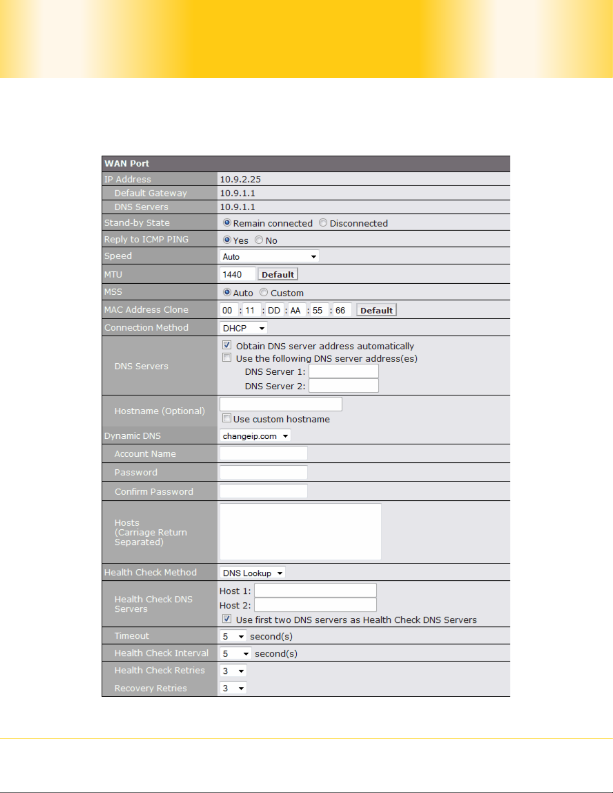
9.1 Ethernet WAN
Pepwave MAX Mobile Router
- 20 -
Copyright © 2009 Pepwave

Ethernet WAN Settings
Stand-by
State
Reply to
ICMP PING
Speed
MTU
MSS
This setting specifies the state of the Ethernet WAN connection. The
available options are Remain Connected and Disconnected.
If this field is disabled, the WAN connection will not respond to ICMP
Ping requests. By default, this is enabled.
This setting specifies port speed and duplex configurations of the
WAN Port.
By default, the appropriate data speed is automatically detected by
Pepwave MAX.
In the event of negotiation issues, the port speed can be manually
specified to circumvent the issues.
This setting specifies the Maximum Transmission Unit.
By default, MTU is set to 1440.
This setting should be configured based on the maximum payload
size that the local system can handle. The MSS (Maximum Segment
Size) is computed from the MTU minus 40 bytes for TCP over IPv4.
If MTU is set to Auto, the MSS will also be set automatically .
By default, MSS is set to Auto.
MAC
Address
Clone
Connection
Method
This setting allows configuring a user-specified MAC address.
Some service providers (e.g. cable providers) identify the clients’
MAC addresses and require the client to always connect using the
same MAC address. In such cases, change the Pepwave MAX WAN
interface MAC address to the original client PC’s via this field.
The default MAC Address is a unique value assigned at the factory.
In most cases, the default value suffices. Clicking the Default
button restores the MAC Address to the default value.
There are three possible connection methods for Ethernet WAN:
DHCP
Static IP
PPPoE
The connection method and details are determined by, and can be
obtained from, the ISP.
See the Sections 9.1.1, 9.1.2, and 9.1.3 for details of each
connection method.
Pepwave MAX Mobile Router
- 21 -
Copyright © 2009 Pepwave

Dynamic
DNS
Health
Check
Method
Ethernet WAN Settings
This setting specifies the dynamic DNS service provider to be used
for the WAN based on supported dynamic DNS service providers:
changeip.com
dyndns.org
no-ip.org
tzo.com
Select Disabled to disable this feature.
See Section 9.1.4 for configuration details.
This setting specifies the health check method for the WAN
connection. The value of method can be configured as Disabled,
Ping or DNS Lookup. The default method is Disabled.
See Section 9.1.5 for configuration details.
9.1.1 DHCP Connection
The DHCP connection method is suitable if the ISP provides an IP address automatically by
DHCP (e.g. Cable, Metro Ethernet, etc.).
DHCP Settings
Each ISP may provide a set of DNS servers for DNS lookups. This
setting specifies the DNS (Domain Name System) Servers to be
used when a DNS lookup is routed through this connection.
Selecting Obtain DNS server address automatically results in
the DNS Servers to be assigned by the WAN DHCP Server to be
DNS Servers
used for outbound DNS lookups over the connection. (The DNS
Servers are obtained along with the WAN IP address assigned from
the DHCP server.)
When Use the following DNS server address(es) is selected,
you may enter custom DNS server addresses for this WAN
connection into the DNS server 1 and DNS server 2 fields.
Pepwave MAX Mobile Router
- 22 -
Copyright © 2009 Pepwave
If your service provider's DHCP server requires you to supply a
Hostname
hostname value upon acquiring an IP address, you may enter the
value here. If your service provider does not provide you with the
value, you can safely bypass this option.
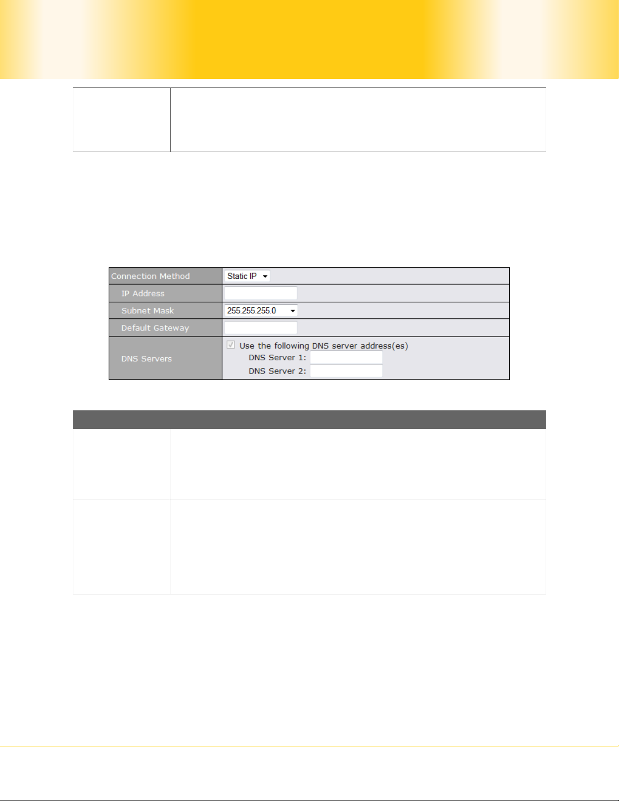
9.1.2 Static IP Connection
This Static IP connection method is suitable if ISP provides a static IP address to connect
directly.
IP Address /
Subnet Mask
/ Default
Gateway
DNS Servers
Static IP Settings
These settings specify the information required in order to
communicate on the Internet via a fixed Internet IP address.
The information is typically determined by and can be obtained from
the ISP.
Each ISP may provide a set of DNS servers for DNS lookups. This
field specifies the DNS (Domain Name System) Servers to be used
when a DNS lookup is routed through this connection.
You can input the ISP provided DNS server addresses into the DNS
server 1 and DNS server 2 fields. If no address is entered here,
this link will not be used for DNS lookups.
Pepwave MAX Mobile Router
- 23 -
Copyright © 2009 Pepwave
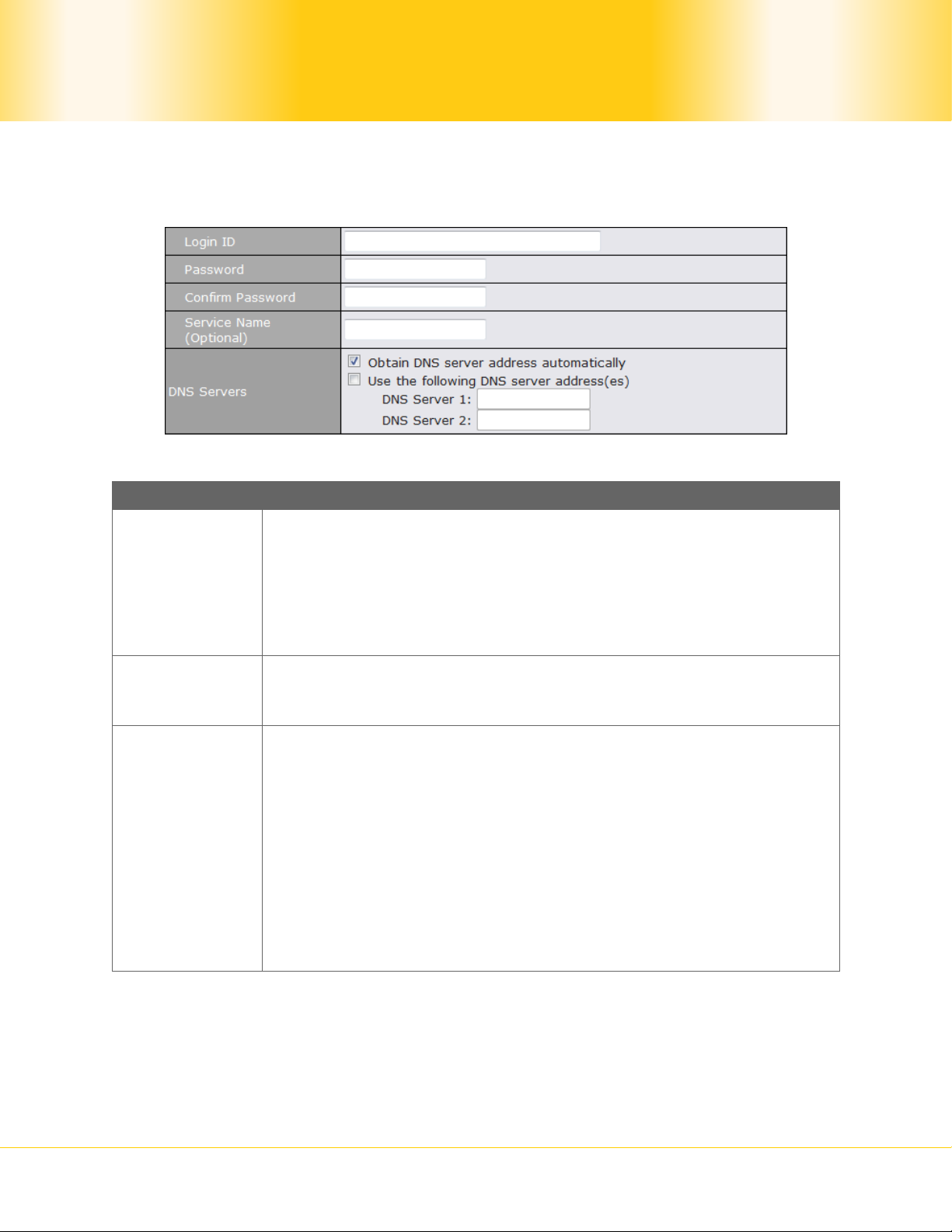
9.1.3 PPPoE Connection
The PPPoE connection method is suitable if the ISP provides a PPPoE login ID and password
to connect via PPPoE.
Login ID and
Password
Service Name
(Optional)
DNS Servers
PPPoE Settings
These settings specify the information required in order to conn ect
via PPPoE to the ISP.
The information is typically determined by and can be obtained from
the ISP, and include the following:
Login ID
Password
Service Name is a PPPoE parameter which is provided by the ISP.
Note: Leave this field blank unless it is provided by your ISP.
Each ISP may provide a set of DNS servers for DNS lookups. This
setting specifies the DNS (Domain Name System) Servers to be
used when a DNS lookup is routed through this connection.
Selecting Obtain DNS server address automatically results in
the DNS Servers assigned by the PPPoE server to be used for
outbound DNS lookups over the WAN connection. (The DNS
Servers are obtained along with the WAN IP address assigned from
the PPPoE server.)
When Use the following DNS server address(es) is selected,
you can put custom DNS server addresses for this WAN connection
into the DNS server 1 and DNS server 2 fields.
Pepwave MAX Mobile Router
- 24 -
Copyright © 2009 Pepwave
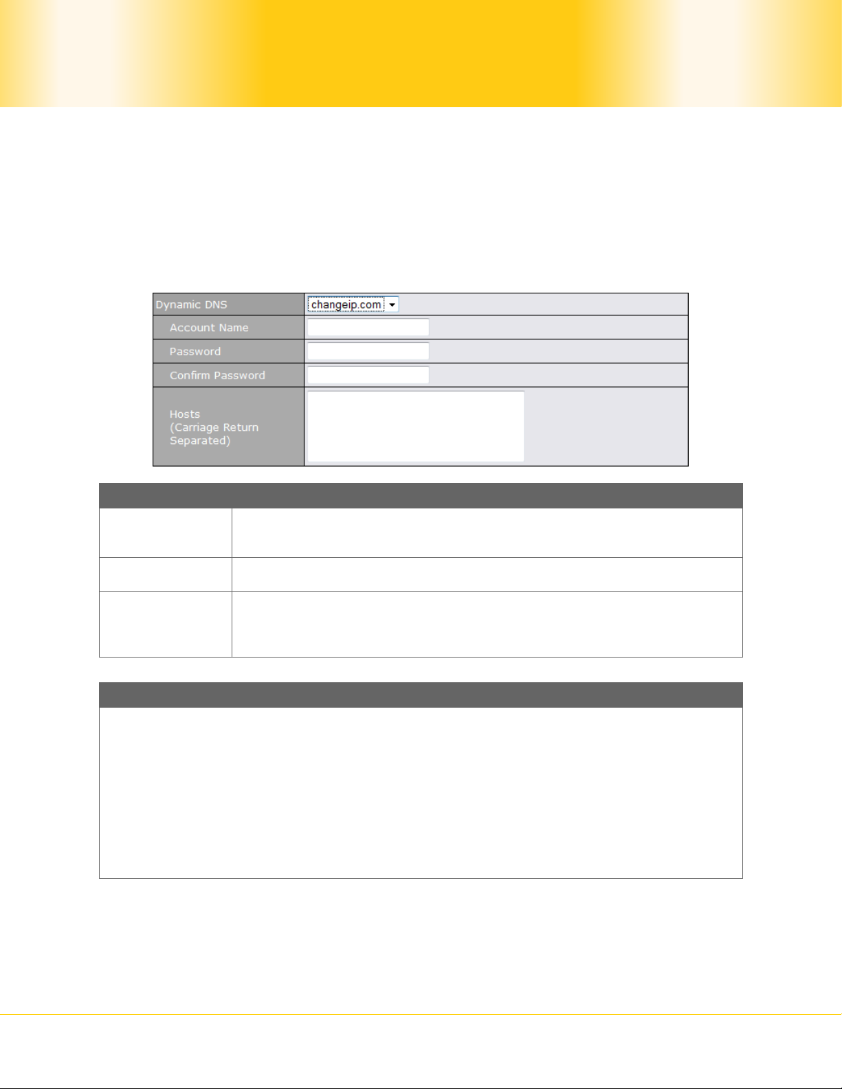
9.1.4 Dynamic DNS Settings
Pepwave MAX provides the functionality to register the domain name relationships to
dynamic DNS service providers. Through registration with dynamic DNS service provider(s),
the default public Internet IP address of each WAN connection can be associated with a host
name.
Either upon a change in IP address or every 23 days without link reconnection, Pepwave
MAX will connect to the dynamic DNS service provider to perform an IP address update
within the provider’s records.
Dynamic DNS Settings
Account
Name
This setting specifies the registered user name for the dynamic DNS
service.
Password This setting specifies the password for the dynamic DNS service.
This setting specifies a list of host names or domains to be
Hosts
associated with the public Internet IP address of the WAN
connection.
Important Note
In order to use dynamic DNS services, appropriate host name registration(s), as well
as a valid account with a supported dynamic DNS service provider are required.
A dynamic DNS update is performed whenever a WAN’s IP address changed. E.g. IP is
changed after a DHCP IP refresh, reconnection, etc.
Due to dynamic DNS service providers’ policy, a dynamic DNS host would expire
automatically because the host record was not updated for a long time. Therefore
Pepwave MAX performs an update every 23 days even if a WAN’s IP address did not
change.
Pepwave MAX Mobile Router
- 25 -
Copyright © 2009 Pepwave

9.1.5 WAN Health Check
To ensure traffic is routed to healthy WAN connections only, Pepwave MAX provides the
functionality to periodically check the health of each WAN connection.
Health Check Settings
Health Check Disabled
When Disabled is chosen in the Method field, the WAN connection will always be
considered as up. The connection will not be treated as down in the event of IP
routing errors.
Health Check Method: Ping
The ICMP Ping packets will be issued to test the connectivity with a configurable target
IP address or host name. A WAN connection is considered as up if ping responses are
received from either one or both of the ping hosts.
This setting specifies IP addresses or host names with which
connectivity is to be tested via ICMP Ping.
If Use first two DNS servers as Ping Hosts is checked, the
target ping host will be the first DNS server f or the corresponding
Ping Hosts
WAN connection.
Reliable ping hosts with a high uptime should be considered.
By default, the first two DNS servers of the WAN connection are
used as the Ping Hosts.
Health Check Method: DNS Lookup
DNS lookups will be issued to test the connectivity with target DNS servers. The
connection will be treated as up if DNS responses are received from either one or both
of the servers, regardless of whether the result was positive or negative.
Pepwave MAX Mobile Router
- 26 -
Copyright © 2009 Pepwave

Other Health Check Settings
Timeout
Health Check
Interval
Health Check
Retries
Recovery
Retries
This setting specifies the timeout, in seconds, for ping/DNS lookup
requests. Default Timeout is set to 5 second.
This setting specifies the time interval, in seconds, between ping or
DNS lookup requests. Default Health Check Interval is 5 seconds.
This setting specifies the number of consecutive ping/DNS lookup
timeouts after which Pepwave MAX is to treat the corresponding
WAN connection as down. Default Health Retries is set to 3.
For example, with the default Health Retries setting of 3, after
consecutive 3 timeouts, the corresponding WAN connection will be
treated as down.
This setting specifies the number of consecutive successful
ping/DNS lookup responses that must be received before the
Pepwave MAX treats a previously down WAN connection to be up
again.
By default, Recover Times is set to 3.
For example, with the default Recover Retries setting of 3, a WAN
connection that was treated as down will be considered to be up
again upon receiving 3 consecutive successful ping/DNS lookup
responses.
Pepwave MAX Mobile Router
- 27 -
Copyright © 2009 Pepwave

9.2 Express Card / PC Card / USB1 / USB2
Wireless
Adaptor
SIM Card
IMSI /
Carrier /
Country
Signal
Strength
IP Address
DNS
Servers
Pepwave MAX Mobile Router
ExpressCard / PC Card / USB Settings
- 28 -
Copyright © 2009 Pepwave

ExpressCard / PC Card / USB Settings
Operator
Settings
Heath
Checking
Settings
Modem
Specific
Settings
9.3 Wi-Fi WAN
Pepwave MAX Mobile Router
- 29 -
Copyright © 2009 Pepwave

Wi-Fi WAN Settings
Network
Name
(SSID)
MAC
Address
(BSSID)
Signal
Strength
IP Address
Default
Gateway
DNS
Servers
Stand-by
State
Reply to
ICMP PING
Health
Check
Method
Wi-Fi
Association
Mode
Connect to
Any Open
Mode AP
Pepwave MAX Mobile Router
- 30 -
Copyright © 2009 Pepwave

10 Advanced Wi-Fi Settings
Advanced Wi-Fi settings are available and can be configured at Advanced > Adv. Wi-Fi
Settings:
Protocol
Operating
Country
Channel
Output Power
Output Power
Pepwave MAX Mobile Router
Wi-Fi AP Radio Settings
Wi-Fi WAN Radio Settings
Wi-Fi AP Advanced Settings
- 31 -
Copyright © 2009 Pepwave

STP
Layer 2
Communication
802.1X Version
Beacon Rate
Beacon Interval
DTIM
RTS Threshold
Slot Time
ACK Timeout
CTS Timeout
Pepwave MAX Mobile Router
- 32 -
Copyright © 2009 Pepwave
11 Site-to-Site VPN
Pepwave Site-to-Site VPN functionality securely connects your office to the company's main
headquarters or to another branch. The data, voice, or video communications between
these locations are kept confidential across the public Internet.
The Site-to-Site VPN of the Pepwave MAX is specifically designed for multi-WAN
environment. The Pepwave MAX can aggregate all WAN connections’ bandwidth for routing
Site-to-Site VPN traffic. Unless all the WAN connections of one site are down, the Pepwave
MAX can still maintain VPN up and running.
Tip
You can define firewall rules to control access within the VPN network. For outbound
policy, you can create a custom outbound rule and choose Any for the WAN
Connection field.
11.1 Configuration of Site-to-Site VPN
Pepwave MAX supports making single Site-to-Site VPN connection with a remote Pepwave
MAX unit or a Peplink Balance 210/310/380/390/700/710.
To configure, navigate to Advanced > Site-to-Site VPN:
Pepwave MAX Mobile Router
- 33 -
Copyright © 2009 Pepwave

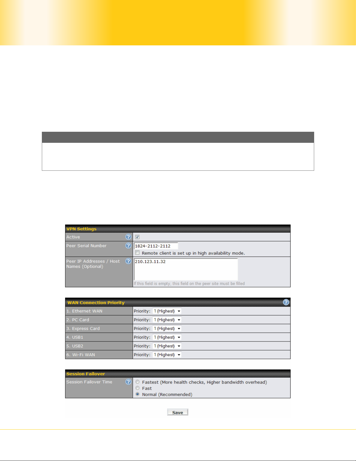
Active Check this box to enable the VPN.
Peer Serial
Number
Peer IP
Addresses /
Host Names
VPN Settings
Pepwave MAX only establishes VPN connection with a remote peer
that has a serial number specified here. If the remote peer is in
high availability setup, you can check the box Remote client is set
up in high availability mode. and enter the second unit's serial
number into the second text box.
Enter the remote peer’s WAN IP address(es) or host name(s) here.
Dynamic-DNS host names are accepted.
This field is optional. With this field filled, the Pepwave MAX will
initiate connection to each of the remote IP addresses until success.
If the field is empty, the Pepwave MAX will wait for connection from
the remote peer. Therefore, at least one side of the two VPN peers
has to have the field filled. Otherwise, VPN connection cannot be
established.
Enter one IP address or host name per line.
WAN
Connection
Priority
Session
Failover Time
WAN Connection Priority
You can specify the priority of the WAN connections to be used for
making VPN connections. WAN connections set to OFF will never
be used. Only available WAN connections with the highest priority
will be used for making VPN connections. Outgoing traffic will be
distributed evenly if there is more than one connection having the
same priority.
Session Failover
The Site-to-Site VPN supports TCP/UDP session failover upon link or
routing failure on a path between two sites. It can automatically
detect any failure and route established sessions to a healthy link so
that connected sessions can remain unaffected.
Health check packets are sent between two sites in order to detect
any failure. The more frequent checks it sends, the faster failover it
can perform, but the higher bandwidth overhead will be consumed.
If this settings on the two peers are different, the faster on e will be
used.
Select Fastest when the highest failover speed is request. By
default, Normal failover time is selected.
Pepwave MAX Mobile Router
- 34 -
Copyright © 2009 Pepwave

11.2 Pepwave MAX Behind NAT Router
The Pepwave MAX supports establishing Site-to-Site VPN over WAN connections which are
behind a NAT (Network Address Translation) router.
To be able for a WAN connection behind a NAT router to accept VPN connections, you can
configure the NAT router in front of the WAN connection to forward TCP port 32015 to it.
If one or more WAN connections on Unit A can accept VPN connections (by means of port
forwarding or not) while none of the WAN connections on the peer Unit B can do so, you
should put all public IP addresses or host names of the Unit A to the Unit B’s Peer IP
Addresses / Host Names field. Leave the field in Unit A blank. With such setting, site-to-
site VPN connection can be set up and all WAN connections on both sides will be utilized.
For example, see the following diagram:
One of the WANs of Unit A is non-NAT’d (212.1.1.1). The rest of the WANs on Unit A and all
WANs on Unit B are NAT’d. In such case, the Peer IP Addresses / Host Names field on
the Unit B should be filled with all of the Unit A’s public IP addresses (i.e. 212.1.1.1,
212.2.2.2 and 212.3.3.3), and the field on the Unit A should be left blank.
11.3 VPN Status
VPN Status is shown on the Dashboard as follows:
Pepwave MAX Mobile Router
- 35 -
Copyright © 2009 Pepwave
12 Outbound Policy
Pepwave MAX provides the functionality to flexibly manage and load balance outbound
traffic among the WAN connections.
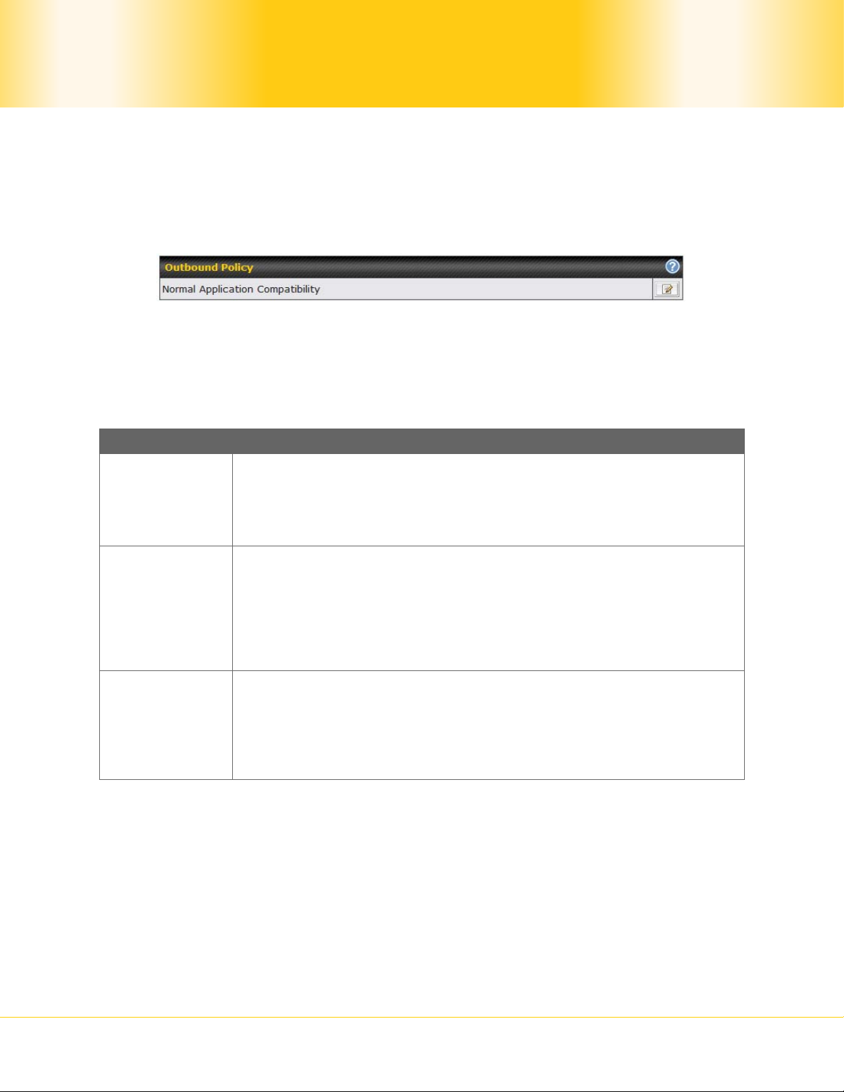
The settings for managing and load balancing outbound traffic are located in
Advanced > Outbound Policy:
There are three main selections for the Outbound Policy for Pepwave MAX:
High Application Compatibility
Normal Application Compatibility
Managed by Custom Rules
The selections are explained as follows:
Outbound Policy Settings
High
Application
Compatibility
Normal
Application
Compatibility
Managed by
Custom Rules
The default policy is Normal Application Compatibility.
With the selection of this policy, outbound traffic from a source LAN
device is routed through the same WAN connection regardless of
the destination Internet IP address and protocol.
This provides the highest application compatibility.
With the selection of this policy, outbound traffic from a source LAN
device to the same destination Internet IP address will p ersistently
be routed through the same WAN connection regardless of protocol.
This provides high compatibility to most applications, and users still
benefit from WAN link load balancing when mu ltiple Internet servers
are accessed.
With the selection of this policy, outbound traffic behavior can be
managed by defining custom rules.
Rules can be defined in a custom rule table. A default rule can be
defined for connections that cannot be matched with any one of the
rules.
Pepwave MAX Mobile Router
- 36 -
Copyright © 2009 Pepwave
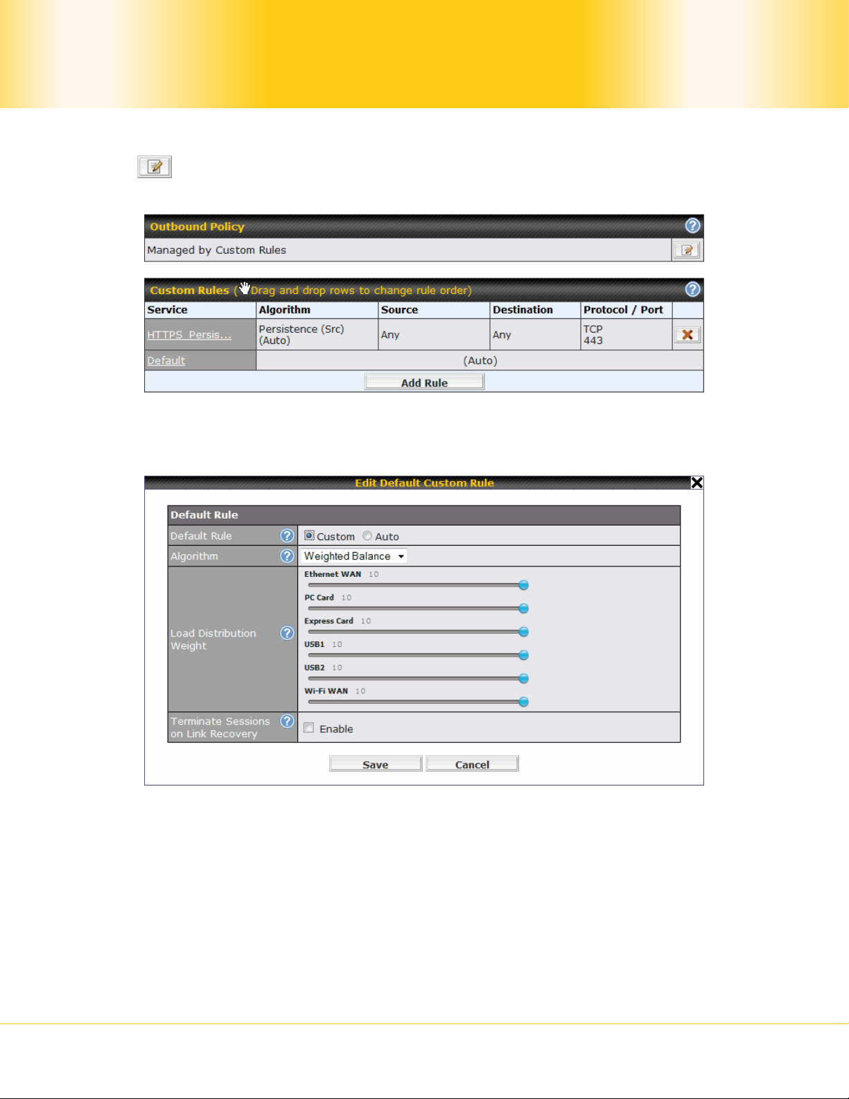
12.1 Custom Rules For Outbound Traffic Management
Click in the Ou tbound Policy form. Choose Managed by Custom Rules and press the
Save button. The following screen will then be display ed.
The bottom-most rule is Default. Edit this rule to change the device’s default way to
control outbound traffic for all connections that does not match any rules above it. Click on
the service name Default to change its settings.
By default, Auto is selected for the option Default Rule. You can select Custom in order
to change the Algorithm to be used. Please refer to the upcoming sections for the details of
the available algorithms.
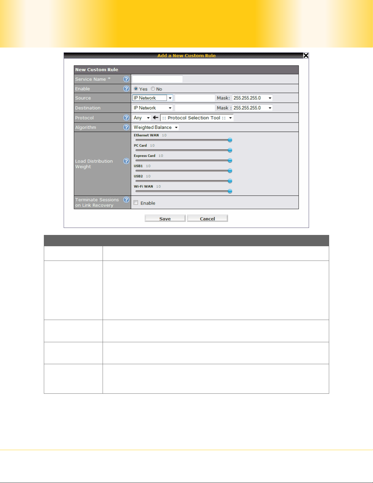
To create a custom rule, click Add Rule at the bottom of the table, and the following
window will be displayed:
Pepwave MAX Mobile Router
- 37 -
Copyright © 2009 Pepwave
New Custom Rule Settings
Service Name This setting specifies the name of the custom rule.
This setting specifies whether the custom rule will take effect.
When Yes is selected, the custom rule takes effect. If the outbound
Enable
traffic matches the specified IP/Protocol/Port, action will be taken
by Pepwave MAX based on the other parameters of the rule.
When No is selected, the custom rule does not take effect.
Pepwave MAX will disregard the other parameters of the rule.
Source
Destination
Protocol and
Port
This setting specifies the source IP Address, IP Network or MAC
Address for outbound traffic that matches the rule.
This setting specifies the destination IP Address or IP Network for
outbound traffic that matches the rule.
This setting specifies the IP Protocol and Port of outbound traffic
that matches this rule. You may select some common protocol
from the Protocol Selection Tool drop-down menu.
Pepwave MAX Mobile Router
- 38 -
Copyright © 2009 Pepwave

Algorithm
Terminate
Sessions on
Link Recovery
New Custom Rule Settings
This setting specifies the behavior of Pepwave MAX for the custom
rule.
One of the following values can be selected:
Weighted Balance
Persistence
Enforced
Priority
Least Used
Lowest Latency
The upcoming sections present the details of the above
Algorithms.
This setting specifies whether to terminate existing IP sessions on a
less preferred WAN connection in the event that a more preferred
WAN connection is recovered. This setting is applicable to the
Algorithms: Weighted, Persistence and Priority.
By default, this is disabled. In this case, all existing IP sessions will
not be terminated or affected when any other WAN connection is
recovered. If it is set to enabled, existing IP sessions may be
terminated when another WAN connection is recovered such that
only the preferred healthy WAN connection(s) are used at any point
in time.
12.1.1 Algorithm: Weighted Balance
This setting specifies the ratio of WAN connection usage to be applied on the specified IP
Protocol & Port, and is applicable only when Algorithm is set to Weighted Balance.
The amount of matching traffic that is distributed to a WAN connection is proportional to the
weight of the WAN connection relative to the total weight. Use the sliders to change the
weight for each WAN.
Example: With the following weight settings:
Ethernet WAN: 10
PC Card: 0
Pepwave MAX Mobile Router
- 39 -
Copyright © 2009 Pepwave
Express Card: 0
USB1: 10
USB2: 0
Wi-Fi WAN: 5
Total weight is 25 = (10 + 0 + 0 + 10 + 0 + 5)
Matching traffic distributed to Ethernet WAN is 40% = (10 / 25) x 100%
Matching traffic distributed to PC Card is 0% = (0 / 25) x 100%
Matching traffic distributed to Express Card is 0% = (0 / 25) x 100%
Matching traffic distributed to USB1 is 40% = (10 / 25) x 100%
Matching traffic distributed to USB2 is 0% = (0 / 25) x 100%
Matching traffic distributed to Wi-Fi WAN is 20% = (5 / 25) x 100%
12.1.2 Algorithm: Persistence
The configuration of using Persistence for algorithm is the solution to the few situations
where link load distribution for Internet services is undesirable.
For example, many e-banking and other secure websites, for security reasons, terminate
the session when the client computer’s Internet IP address changes during the session.
In general, different Internet IP addresses represent different computers. The security
concern is that an IP address change during a session may be the result of an unauthorized
intrusion attempt. Therefore, to prevent damages from the potential intrusion, the session
is terminated upon the detection of an IP address change.
Pepwave MAX can be configured to distribute data traffic across multiple WAN connections.
Also, the Internet IP depends on the WAN connections over which communication actually
takes place. As a result, a LAN client computer behind Pepwave MAX may communicate
using multiple Internet IP addresses. For example, a LAN client computer behind a
Pepwave MAX with three WAN connections may communicate on the Internet using three
different IP addresses.
With the algorithm Persistence of Pepwave MAX, rules can be configured to enable client
computers to persistently utilize the same WAN connections for e-ban king and other secure
websites. As a result, a client computer will communicate with the other end using one IP
address and eliminate the issues.
Pepwave MAX Mobile Router
- 40 -
Copyright © 2009 Pepwave

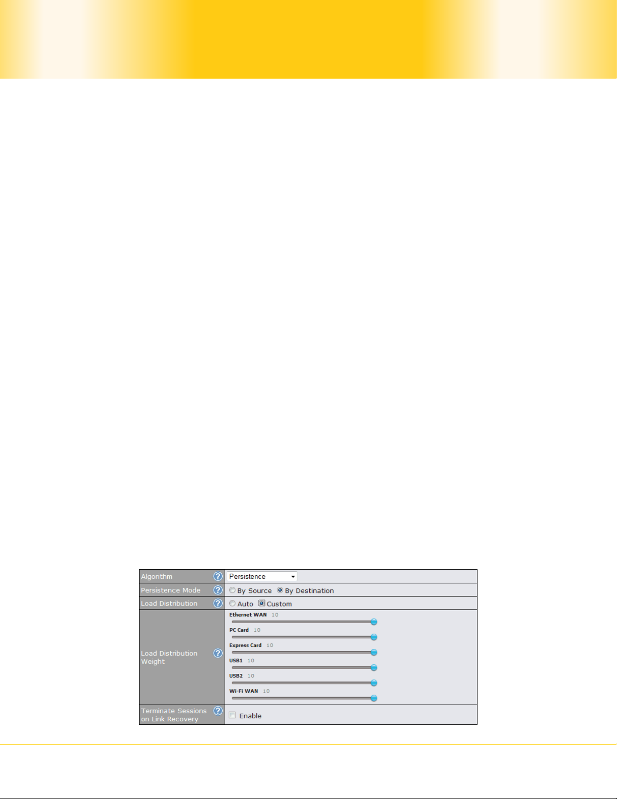
There are two modes for Persistence: By Source and By Destination.
The same WAN connection will be used for traffic matching the
By Source
rule and originating from the same machine regardless of its
destination. This option will provide the highest level of
application compatibility.
The same WAN connection will be used for traffic matching the
By Destination
rule, originating from the same machine, and going to the same
destination. This option can better distribute load to WAN
connections when there are only a few client machines.
The default mode is By Source.
When there are multiple client requests, they can be distributed (persistently) to WAN
connections with a weight. If you choose Auto in the field Load Distribution, the weights
will be automatically adjusted according to each WAN’s Downstream Bandwidth which is
specified in the WAN settings page (see Section 9 Configuration of WAN Interface(s )).
If you choose Custom, you can customize the weight of each WAN manually by using the
sliders.
12.1.3 Algorithm: Enforced
This setting specifies the WAN connection usage to be applied on the specified IP Protocol &
Port, and is applicable only when the Algorithm is set t o Enforced.
Matching traffic will be routed through the specified WAN connection regardless of the
connection’s health check status.
12.1.4 Algorithm: Priority
This setting specifies the priority of the WAN connection s to be ut ilize d t o rou te th e specified
network service. The highest priority WAN connection available will always be used for
routing the specified type of traffic. A lower priority WAN connection will be us ed only when
all higher priority connections have become unavailable.
Pepwave MAX Mobile Router
- 41 -
Copyright © 2009 Pepwave

Tip
Configure multiple distribution rules to accommodate different kinds of services.
12.1.5 Algorithm: Least Used
The traffic matching this rule will be routed through the healthy WAN connection with the
most available downstream bandwidth. The available downstream bandwidth of a WAN
connection is calculated from the total downstream bandwidth specified in the WAN sett ings
page, and the current downstream usage. The available bandwidth and WAN selection is
determined every time an IP session is made.
12.1.6 Algorithm: Lowest Latency
The traffic matching this rule will be routed through the healthy WAN connection with the
lowest latency. Active pings are issued periodically to a nearby router of each WAN
connection. The latency of a WAN is the ping round trip time of the WAN connection.
Tip
The round trip time of a 6M down / 640k up link can be higher than that of a 2M down
/ 2M up link. It is because the overall round trip time is lengthened by its slower
upstream bandwidth despite of its higher downlink speed. Therefore this algorithm is
good for two scenarios:
1. All WAN connections are symmetric; or
2. A latency sensitive applicat ion requires to be routed through the lowest latency WAN
regardless the WAN’s available bandwidth.
Pepwave MAX Mobile Router
- 42 -
Copyright © 2009 Pepwave

13 Service Forwarding
Service Forwarding settings are located at Advanced > Service Forwarding:
13.1 SMTP Forwarding
Some ISPs require their users to send e-mails via the ISP’s SMTP server. All outgoing SMTP
connections are blocked except those connecting to the ISP’s. The Pepwave MAX supports
intercepting and redirecting all outgoing SMTP connections (destined for TCP port 25) via a
WAN connection to the WAN’s corresponding SMTP server.
To enable the feature, select the Enable check box under SMTP Forwarding Setup. Check
the box Enable Forwarding? for the WAN connection(s) that needs such forwarding. Enter
the ISP’s e-mail server address and TCP port number for each WAN.
The Pepwave MAX will intercept SMTP connections, choose a WAN with reference to the
Outbound Policy, and then forward the connection to the forwarded SMTP server if the
chosen WAN has enabled forwarding. If the forwarding is disabled for a WAN connection,
SMTP connections for the WAN will be simply forwarded to the connection’s original
destination.
Note
If you want to route all SMTP connections only to particular WAN connection(s), you
should create a rule in Outbound Policy (see Section Error! Reference source not
found.).
Pepwave MAX Mobile Router
- 43 -
Copyright © 2009 Pepwave

13.2 Web Proxy Forwarding
When this feature is enabled, the Pepwave MAX will intercept all outgoing connections
destined for the proxy server specified in Web Proxy Interception Settings, choose a WAN
connection with reference to the Outbound Policy, and then forward them to the specified
web proxy server and port number. Redirected server settings for each WAN can be set
here. If forwarding is disabled for a WAN, web proxy connections for the WAN will be
simply forwarded to the connection’s original destination.
13.3 DNS Forwarding
When DNS Forwarding is enabled, all clients’ outgoing DNS requests will also be intercepted
and forwarded to the built-in DNS proxy server.
Pepwave MAX Mobile Router
- 44 -
Copyright © 2009 Pepwave

14 Port Forwarding
When operating under NAT mode, Pepwave MAX acts as a firewall that blocks, by default, all
inbound access from the Internet.
By the Port Forwarding, Internet users can access the servers behind Pepwave MAX.
Important Note
Port Forwarding applies only to WAN connections that are operating under NAT mode.
For WAN connections operating under IP forwarding, inbound traffic is forwarded to the
LAN by default.
Inbound Port Forwarding rules can be defined at Advanced > Port Forwarding:
To define a new service, click the Add Service button, upon which the following appears:
Port Forwarding Settings
Pepwave MAX Mobile Router
- 45 -
Copyright © 2009 Pepwave

Enable
Service Name
Port Forwarding Settings
This setting specifies whether the inbound service rule tak es effect.
When Yes is selected, the inbound service rule takes effect. If the
inbound traffic matches the specified IP Protocol and Port, action
will be taken by Pepwave MAX based on the other parameters of the
rule.
When No is selected, th e inbound service rule does not take effect.
Pepwave MAX will disregard the other parameters of the rule.
This setting identifies the service to the System Administrator.
Valid values for this setting consist only of alphanumeric and the
underscore “_” characters.
The IP Protocol setting, along with the Port setting, specifies the
protocol of the service as TCP, UDP, ICMP or IP.
Traffic that is received by Pepwave MAX via the specified protocol at
the specified port(s) is forwarded to the LAN hosts specified by the
Servers setting.
IP Protocol
(Please see below for details on the Port and Servers settings.)
Alternatively, the Protocol Selection Tool drop-down menu can be
used to automatically fill in the Protocol and a single Port number of
common Internet services (e.g. HTTP, HTTPS, etc.).
After selecting an item from the Protocol Selection Tool drop-
down menu, the Protocol and Port number remains manually
modifiable.
Pepwave MAX Mobile Router
- 46 -
Copyright © 2009 Pepwave

Port Forwarding Settings
The Port setting specifies the port(s) that correspond to the service,
and can be configured to behave in one of the following manners:
Any Port, Single Port, Port Range and Port Map
Any Port: All traffic that is received by Pepwave MAX via the
specified protocol is forwarded to the servers specified by the
Servers setting.
For example, with IP Protocol set to TCP, and Port set to Any Port,
all TCP traffic is forwarded to the configured servers.
Single Port: Traffic that is received by Pepwave MAX via the
specified protocol at the specified port is forwarded via the same
port to the servers specified by the Servers setting.
For example, with IP Protocol set to TCP, and Port set to Single
Port and Service Port 80, TCP traffic received on Port 80 is
forwarded to the configured servers via Port 80.
Port
Port Range: Traffic that is received by Pepwave MAX via the
specified protocol at the specified port range is forwarded via the
same respective ports to the LAN hosts specified by the Servers
setting.
Inbound IP
Address(es)
Server IP
Address
For example, with IP Protocol set to TCP, and Port set to Single
Port and Service Port 80-88, TCP traffic received on ports 80
through 88 is forwarded to the configured servers via the respective
ports.
Port Map: Traffic that is received by Pepwave MAX via the specified
protocol at the specified port is forwarded via a different port to the
servers specified by the Servers setting.
For example, with IP Protocol set to TCP, and Port set to Port Map,
Service Port 80, and Map to Port 88, TCP traffic on Port 80 is
forwarded to the configured servers via Port 88.
(Please see below for details on the Servers setting.)
This setting specifies the WAN connections and Internet IP
address(es) from which the service can be accessed.
This setting specifies the LAN IP address of the server that handles
the requests for the service.
Pepwave MAX Mobile Router
- 47 -
Copyright © 2009 Pepwave
15 NAT Mappings
The configuration of NAT Mappings allows the IP address mapping of all inbound and
outbound NAT’ed traffic to and from an internal client IP address.
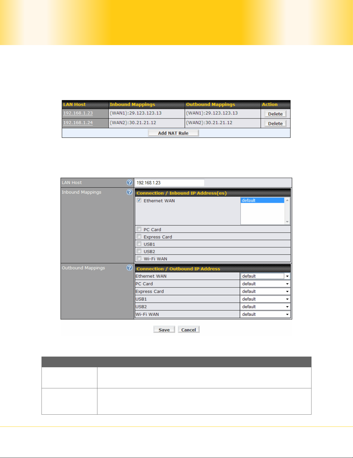
The settings to configure NAT Mappings are located at Advanced > NAT Mappings:
To add a rule for NAT Mappings, click Add NAT Rule, upon which the following screen will
be displayed:
NAT Mapping Settings
LAN Host
Inbound
Mappings
Pepwave MAX Mobile Router
This is the IP address of the host on the LAN that the system should
map the selected connection IP address correspondences.
This setting specifies the WAN connections and corresponding WANspecific Internet IP addresses on which the system should bind on.
Any access to the specified WAN connection(s) and IP address(es)
- 48 -
Copyright © 2009 Pepwave

will be forwarded to the LAN Host.
Note 1: Inbound Mapping is not needed for WAN connections in IP
forwarding mode.
Note 2: Each WAN IP address can be associated to one NAT
Mapping only.
This setting specifies the IP address of each WAN connection to be
used for any outgoing traffic originating from the LAN Host.
Outbound
Mappings
Note 1: If you do not want to use a specific WAN for outgoing
accesses, you should still choose Default here, then customize the
outbound access rule in the Outbound Policy section.
Note 2: WAN connections in IP forwarding mode are not shown
here.
Click Save to save the settings when configuration has been completed.
Important Note
Inbound firewall rules override the Inbound Mapping settings.
Pepwave MAX Mobile Router
- 49 -
Copyright © 2009 Pepwave
16 Firewall
A firewall is a mechanism that selectively filters data traffic between the WAN side (the
Internet) and the LAN side of the network. It can protect the local network from potential
hacker attacks, offensive Web sites, and/or other inappropriate uses.
The firewall functionality of Pepwave MAX supports the selective filtering of data traffic in
both directions:
Outbound (LAN to WAN)
Inbound (WAN to LAN)
Intrusion Detection and DoS Prevention
With Site-to-Site VPN enabled (see Section 11), the firewall rules also apply to VPN tunneled
traffic.
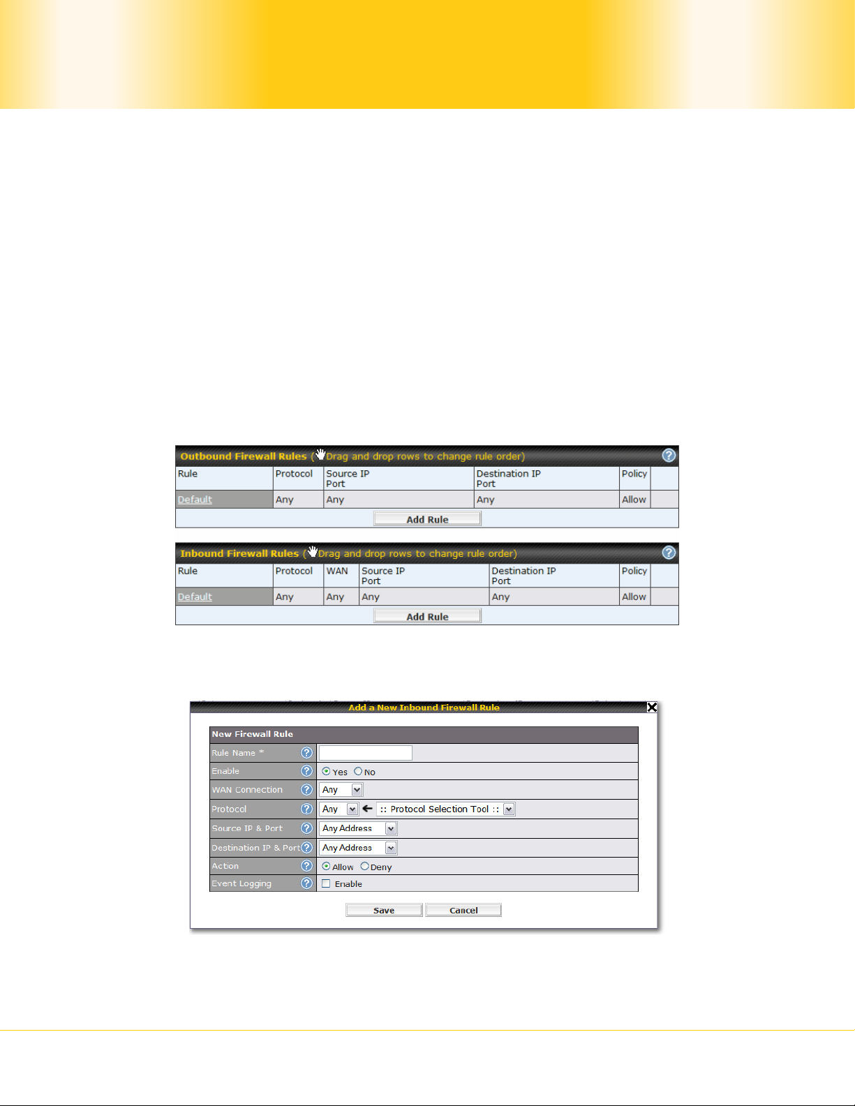
16.1 Outbound and Inbound Firewall
The outbound and inbound firewall settings are located in Advanced > Firewall:
Upon clicking Add Rule, the following screen appears:
Pepwave MAX Mobile Router
- 50 -
Copyright © 2009 Pepwave

Inbound / Outbound Firewall Settings
Rule Name This setting specifies a name for the firewall rule.
This setting specifies whether the firewall rule should take eff ect.
When Yes is selected, the firewall rule takes effect. If the traffic
Enable
matches the specified Protocol/IP/Port, actions will be taken by
Pepwave MAX based on the other parameters of the rule.
When No is selected, the firewall rule does not take effect.
Pepwave MAX will disregard the other parameters of the rule.
This setting is applicable to Inbound Firewall Rules only.
This setting specifies which WAN connection(s) the ru le applies to:
Any (applies to all WAN connections)
WAN
Connection
Ethernet WAN
PC Card
Express Card
USB1
USB2
Wi-Fi WAN
Protocol
Source IP &
Port
This setting specifies the protocol to be matched by the rule.
Via a drop-down menu, the following protocols can be specified:
TCP
UDP
ICMP
IP
Alternatively, the Protocol Selection Tool drop-down menu can be
used to automatically fill in the Protocol and Port number of
common Internet services (e.g. HTTP, HTTPS, etc.)
After selecting an item from the Protocol Selection Tool drop-
down menu, the Protocol and Port number remains manually
modifiable.
This specifies the source IP address(es) and port number(s) to be
matched for a firewall rule.
A single address, or a network, can be specified as the Source IP &
Port setting, as indicated with the following screenshots:
In addition, a single port, or a range of ports, can be specified for
the Source IP & Port setting.
Pepwave MAX Mobile Router
- 51 -
Copyright © 2009 Pepwave
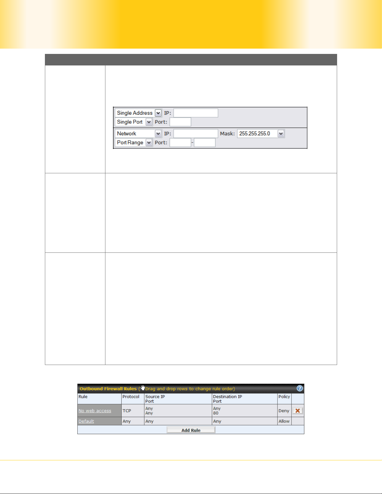
Destination IP
& Port
Inbound / Outbound Firewall Settings
This specifies the destination IP address(es) and port number(s) to
be matched for a firewall rule.
A single address, or a network, can be specified as the Source IP &
Port setting, as indicated with the following screenshots:
In addition, a single port, or a range of ports, can be specified for
the Source IP & Port setting.
This setting specifies the action to be taken by Pepwave MAX upon
encountering traffic that matches the both of the following:
Source IP & Port
Destination IP & Port
Action
With the value of Allow for the Action setting, the matching traffic
passes through Pepwave MAX (to be routed to the destination).
If the value of the Action setting is set to Deny, the matching traffic
does not pass through Pepwave MAX (and is discarded).
This setting specifies whether or not to log matched firewall events.
The logged messages are shown on the page Status > Event Log.
A sample message is as follows:
Aug 13 23:47:44 Denied CONN=Ethernet WAN SRC=20.3.2.1
Event
Logging
DST=192.168.1.20 LEN=48 PROTO=TCP SPT=2260 DPT=80
CONN: The connection where the log entry refers to
SRC: Source IP address
DST: Destination IP address
LEN: Packet length
PROTO: Protocol
SPT: Source port
DPT: Destination port
Upon clicking Save after entering required information, the following screen appears.
Pepwave MAX Mobile Router
- 52 -
Copyright © 2009 Pepwave
To create an additional firewall rule, click Add Rule and repeat the above steps.
To reorder a rule’s position, just drag the rule by holding th e left mouse button, move it to
the desired position, and place it by releasing the mouse button.
To remove a rule, click
.
Rules are matched from top to the bottom. If a connection matches any one of the upper
rules, the matching process will stop. If none of the rules is matching, the Default rule will
be applied.
By default, the Default rule is “Allow” for both outbound and inbound accesses.
Tip
If the default inbound rule is “Allow” for NAT enabled WANs, no inbound “Allow”
firewall rules will be required for inbound Port Forwarding and inbound NAT Mapping
rules. However, if the default inbound rule is “Deny”, corresponding “Allow” firewall
rules will be required.
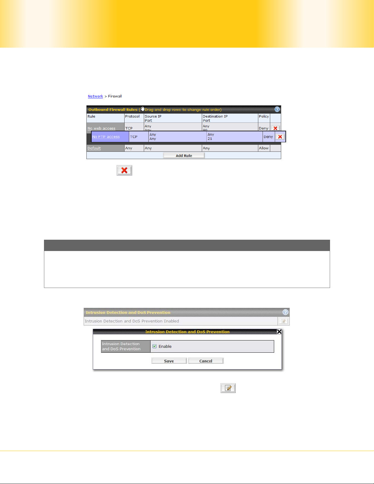
16.2 Intrusion Detection and DoS Prevention
The Pepwave MAX supports detecting and preventing intrusions and Denial-of-Service (DoS)
attacks from the Internet. To turn on this feature, click
, check the box Enable for the
Intrusion Detection and DoS Prevention and press the Save button.
When this feature is enabled, the Pepwave MAX will detect and protect the network from the
following kinds of intrusions and denial-of- service attacks.
Pepwave MAX Mobile Router
- 53 -
Copyright © 2009 Pepwave
Port Scan:
NMAP FIN/URG/PSH
Xmas Tree
Another Xmas Tree
Null Scan
SYN/RST
SYN/FIN
SYN Flood Prevention
Ping Flood Attack Prevention
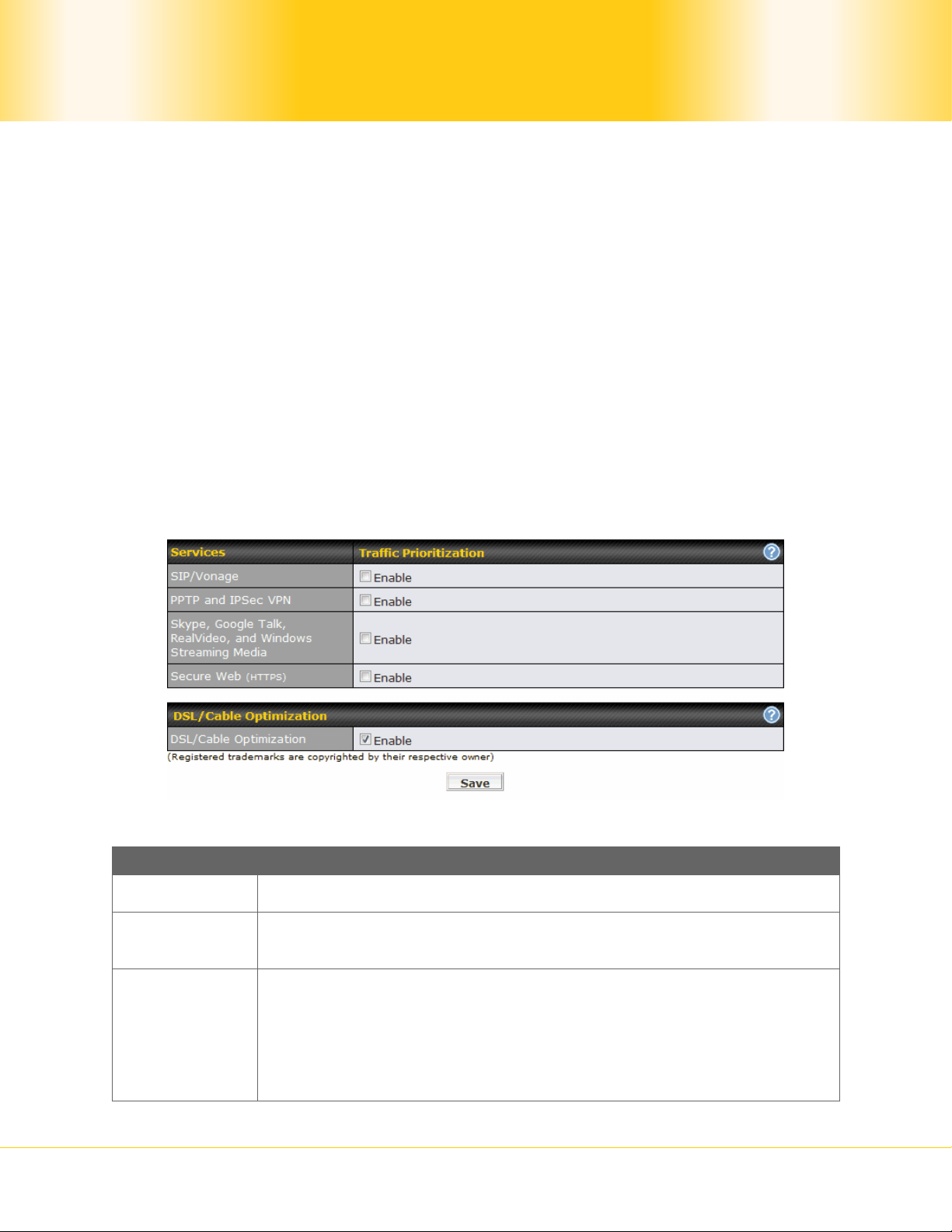
17 Traffic Prioritization
Pepwave MAX provides the functionality to prioritize Voice over IP, VPN, video streaming,
Secure Web over the other Internet traffic.
The settings for configuring Quality of Service are located at Advanced > Traffic
Prioritization:
Traffic Prioritization
SIP/Vonage When enabled, any SIP and Vonage voice traffic will be prioritized.
PPTP and
IPSec VPN
When enabled, any PPTP and IPSec traffic will be prioritiz ed
Skype,
Google Talk,
RealVideo,
and Windows
Streaming
Media
Pepwave MAX Mobile Router
When enabled, voice and video traffic of Skype, Google Talk,
RealVideo and Windows Streaming Media will be prioritized.
(Registered trademarks are copyrighted by their respective owner)
- 54 -
Copyright © 2009 Pepwave
Secure Web
(HTTPS)
DSL/Cable
Optimization
Please note that the Pepwave MAX prioritizes only outbound packets. E.g. for secure web
prioritization, the system will prioritize uploading traffic for outgoing connections and
downloading traffic for incoming connections.
When enabled, HTTPS (TCP port 443) traffic will be prioritized.
DSL/Cable Optimization
For an asymmetric DSL (ADSL) or Cable based WAN connection,
where the upstream bandwidth is lower than the downstream, with
this option turned on, the WAN's downstream bandwidth can be
fully utilized in any situation.
When a DSL or a Cable circuit's uplink becomes busy, it is a fact
that the downlink bandwidth is affected. Users cannot download
data in full speed until the uplink becomes less congested. The
DSL/Cable Optimization could relieve such problem. When it is
enabled, the download speed will be less affected by upload traffic.
Default: Enabled.
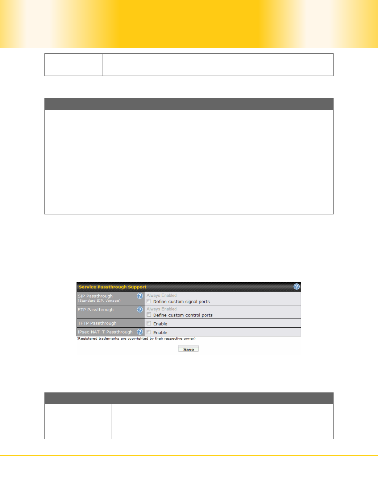
18 Service Passthrough
Service Passthrough settings can be found in Advanced > Service Passthrough:
Some Internet services required to be specially handled in a multi-WAN environment. The
Pepwave MAX supports handling such services correctly such that Internet applications do
not notice it is behind a multi-WAN router. Settings for Service Passthrough Support are
available here.
Service Passthrough Support
Session Initiation Protocol, aka SIP, is a voice-over-IP protocol.
SIP
Passthrough
Pepwave MAX can act as a SIP Application Layer Gateway (ALG)
which binds connections for the same SIP session to the same
WAN connection and translate IP address in the SIP packets
Pepwave MAX Mobile Router
- 55 -
Copyright © 2009 Pepwave

Passthrough
FTP
correctly in NAT mode. Such passthrough support is always
enabled.
If your SIP server’s signal port number is non-standard, you can
check the box Define custom signal ports and input the port
numbers to the text boxes.
FTP sessions consist of two TCP connections; one for control and
one for data. In multi-WAN situation, they have to be binded to
the same WAN connection. Otherwise, problems will arise in
transferring files. By default, the Pepwave MAX monitors TCP
control connections on port 21 for any FTP connections and binds
TCP connections of the same FTP session to the same WAN.
If you have an FTP server listening on a port number other than
21, you can check the box Define custom control ports and
enter the port numbers to the text boxes.
Passthrough
IPsec NAT-T
Passthrough
TFTP
The Pepwave MAX monitors outgoing TFTP connections and
routes any incoming TFTP data packets back to the client. Select
Enable if you want to enable the TFTP passthrough support.
This field is for enabling the support of IPsec NAT-T passthrough.
UDP ports 500, 4500 and 10000 are monitored by default.
You may add more custom data ports that your IPsec system
uses.
Pepwave MAX Mobile Router
- 56 -
Copyright © 2009 Pepwave
19 System Settings
19.1 Admin Security
For security reasons, after logging in to the administration interface at the first time,
changing the administrator password is recommended.
Configuring the administration interface to be accessible only from the LAN can further
improve system security.
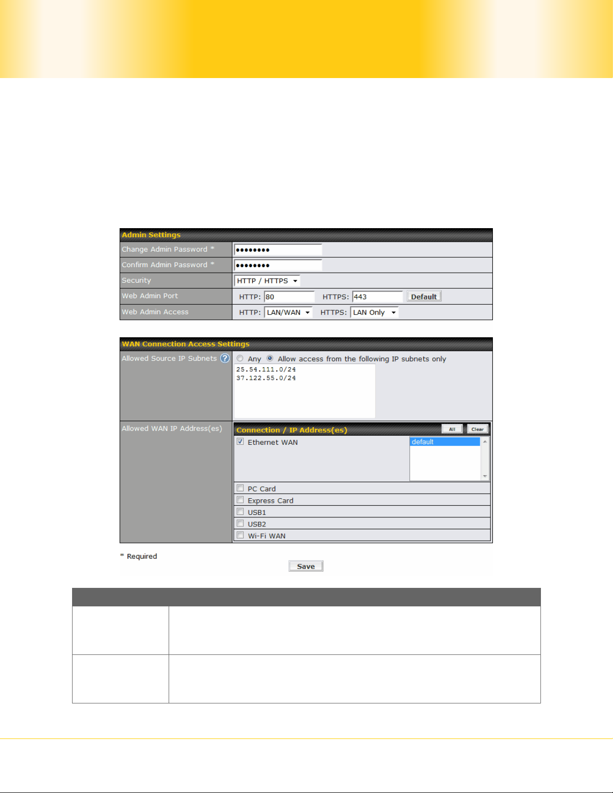
Administrative Settings configuration is located at System > Admin Security:
Admin Settings
Change
Admin
Password
Confirm
Admin
Password
Pepwave MAX Mobile Router
This setting specifies a new administrator password.
This setting verifies and confirms the new administrator password.
- 57 -
Copyright © 2009 Pepwave

Security
This setting specifies the protocol(s) through which the Web
Administration Interface is accessible:
HTTP
HTTPS
HTTP/HTTPS
Web Admin
Web Admin
Access
Port
This setting specifies the port number at which the Web
Administration Interface is accessible.
This setting specifies the network interfaces through which the Web
Administration Interface can be accessed:
LAN only
LAN/WAN
If LAN/WAN is chosen, a WAN Connection Access Settings form
will be displayed.
WAN Connection Access Settings
Allowed Source IP Subnets(s): To restrict web admin access only from
defined IP subnets.
Any
Allow web admin accesses to be from anywhere, without IP address
restriction.
Allow access from the following IP subnets only
Restrict web admin access only from the defined IP subnets. When
this is chosen, a text input area will be displayed beneath:
Allowed
Source IP
Subnets
The allowed IP subnet addresses should be entered into this text area.
Each IP subnet must be in form of w.x.y.z/m,
where w.x.y.z is an IP address (e.g. 192.168.0.0), and
m is the subnet mask in CIDR format, which is between 0 and 32
inclusively. For example: 192.168.0.0/24
Pepwave MAX Mobile Router
- 58 -
Copyright © 2009 Pepwave

Allowed
WAN IP
Addresses
To define multiple subnets, separate each IP subnet one in a line. For
example:
192.168.0.0/24
10.8.0.0/16
This is to choose which WAN IP address(es) the web server should
listen on.
19.2 Firmware Upgrade
The firmware of Pepwave MAX is upgradeable through Web Administration Interface.
Firmware upgrade functionality is located at System > Firmware:
There are two ways to upgrade the unit. The first method is online firmware upgrade. The
system can check, download and upgrade over the Internet. The second method is to
upload a firmware file manually.
Click on the Check again button to use online upgrade. With online upgrade, Pepwave
MAX checks online for new firmware. If a new firmware is available, the firmware will be
automatically downloaded by Pepwave MAX. The upgrade process will subsequently be
automatically initiated.
You may also download a firmware image from the Pepwave web site
(http://www.pepwave.com/
) and update the unit manually. Click Browse to select the
firmware file from the local computer, then click Upgrade to send the firmware to Pepwave
MAX. Pepwave MAX will then automatically initiate the firmware upgrade process.
Firmware Upgrade Status
Pepwave MAX Mobile Router
- 59 -
Copyright © 2009 Pepwave

Status LED Information during firmware upgrade:
OFF – Firmware upgrade in progress (DO NOT disconnect power.)
Red – Unit is rebooting
Green – Firmware upgrade successfully completed
Important Note
The firmware upgrade process may not necessarily preserve the previous
configuration, and the behavior varies on a case-by-case basis. Consult the Release
Notes for the particular firmware version.
Do not disconnect the power during firmware upgrade process.
Do not attempt to upload a non-firmware file, or a firmware file that is not qualified, or
not supported, by Pepwave.
Upgrading a Pepwave MAX Mobile Router with an invalid firmware file wil l damage the
unit, and may void the warranty.
19.3 Time
The Time Server functionality enables the system clock of Pepwave MAX to be synchronized
with a specified Time Server.
The settings for Time Server configuration are located at System > Time:
Time Server Settings
This specifies the time zone (along with the corresponding Daylight
Time Zone
Time Server
Savings Time scheme) in which Pepwave MAX operates.
The Time Zone value affects the time stamps in the Event Log of
Pepwave MAX and E-mail notifications.
This setting specifies the NTP network time server to be utilized by
Pepwave MAX.
Pepwave MAX Mobile Router
- 60 -
Copyright © 2009 Pepwave

19.4 Email Notification
The Email Notification functionality of Pe pwave MAX provides a System Administrator with
up-to-date information on network status.
The settings for configuring Email Notificat ion are found at System > Email Notification:
Email
Notification
SMTP Server
SMTP User
Name /
Password
Sender’s
Email
Address
Recipient’s
Email
Address
Email Notification Settings
This setting specifies whether or not to enable Email Notification.
If the box Enable is checked, Pepwave MAX sends email messages
to a System Administrator when the WAN status changes, or when
new firmware is available.
If the box Enable is not checked, Email Notification is disabled and
Pepwave MAX will not send email messages.
This setting specifies the SMTP server to be used for sending email.
If the Server requires authentication, check the box Require
authentication.
This setting specifies the SMTP username and password while
sending email. These options are shown only if the Require
authentication check box is checked in SMTP Server setting.
This setting specifies the sender email address reported by the
email messages sent by Pepwave MAX.
This setting specifies the email address to which Pepwave MAX
should send the email messages to.
After you have completed the settings, you can click the Test Email Notification button to
Pepwave MAX Mobile Router
- 61 -
Copyright © 2009 Pepwave

test the settings before saving it. After it is clicked, you will see this screen to confirm the
settings:
Click Yes to confirm. Wait a few seconds, and you will see a return message and the
detailed test result.
19.5 Remote Syslog
The Remote Syslog functionality of Pepwave MAX enables event logging at a specified
remote Syslog server.
The settings for configuring Remote System Log are found at System > Remote Syslog:
Remote Syslog Settings
Remote
Syslog
Remote This setting specifies the IP address or host name of the remote
This setting specifies whether or not to log events at the specified
remote Syslog server.
Pepwave MAX Mobile Router
- 62 -
Copyright © 2009 Pepwave

Syslog Host Syslog server.
Port
This setting specifies the port number of the remote Syslog service.
By default, the Port setting has value is 514.
19.6 SNMP
SNMP, or Simple Network Management Protocol, is an open standard that can be used to
collect information from the Pepwave MAX Mobile Router.
SNMP configuration is located at System > SNMP:
SNMP Settings
SNMP Server
Name
This setting specifies the SNMP server name.
SNMPv1 This setting specifies that SNMP version 1 is to be enabled.
SNMPv2c This setting specifies that SNMP version 2 is to be enabled.
SNMPv3 This setting specifies that SNMP version 3 is to be enabled.
To add a community for either SNMPv1 or SNMPv2c, click the Add SNMP Community
button in the Community Name table, upon which the following screen will be displayed:
Pepwave MAX Mobile Router
- 63 -
Copyright © 2009 Pepwave
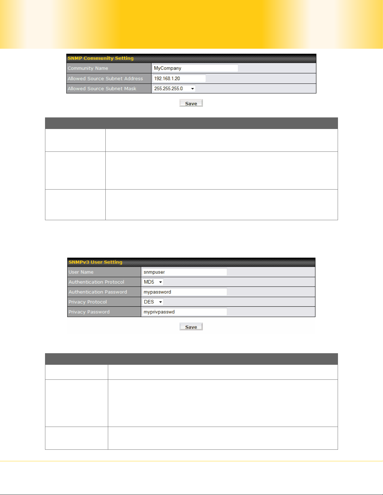
SNMP Community Settings
Community
Name
Allowed
Source
This setting specifies the SNMP Community Name.
This setting specifies a subnet from which access to the SNMP
server is allowed.
Subnet
Address
Allowed
Source
Subnet Mask
Enter subnet address here (e.g. 192.168.1.0).
This setting specifies the subnet mask that corresponds to the
subnet specified via Allowed Source Subnet Address (e.g.
255.255.255.0).
To define a user name for SNMPv3, click Add SNMP User in the SNMPv3 User Name
table, upon which the following screen is displayed:
SNMPv3 User Settings
User Name This setting specifies a user name to be used in SNMPv3.
This setting specifies via a drop-down menu the one of the
Authentication
Protocol
following valid authentication protocols:
NONE
MD5
SHA
Authentication
Password
Pepwave MAX Mobile Router
This setting specifies the authentication password, and is applicable
only if the MD5 or SHA authentication protocol is selected.
- 64 -
Copyright © 2009 Pepwave
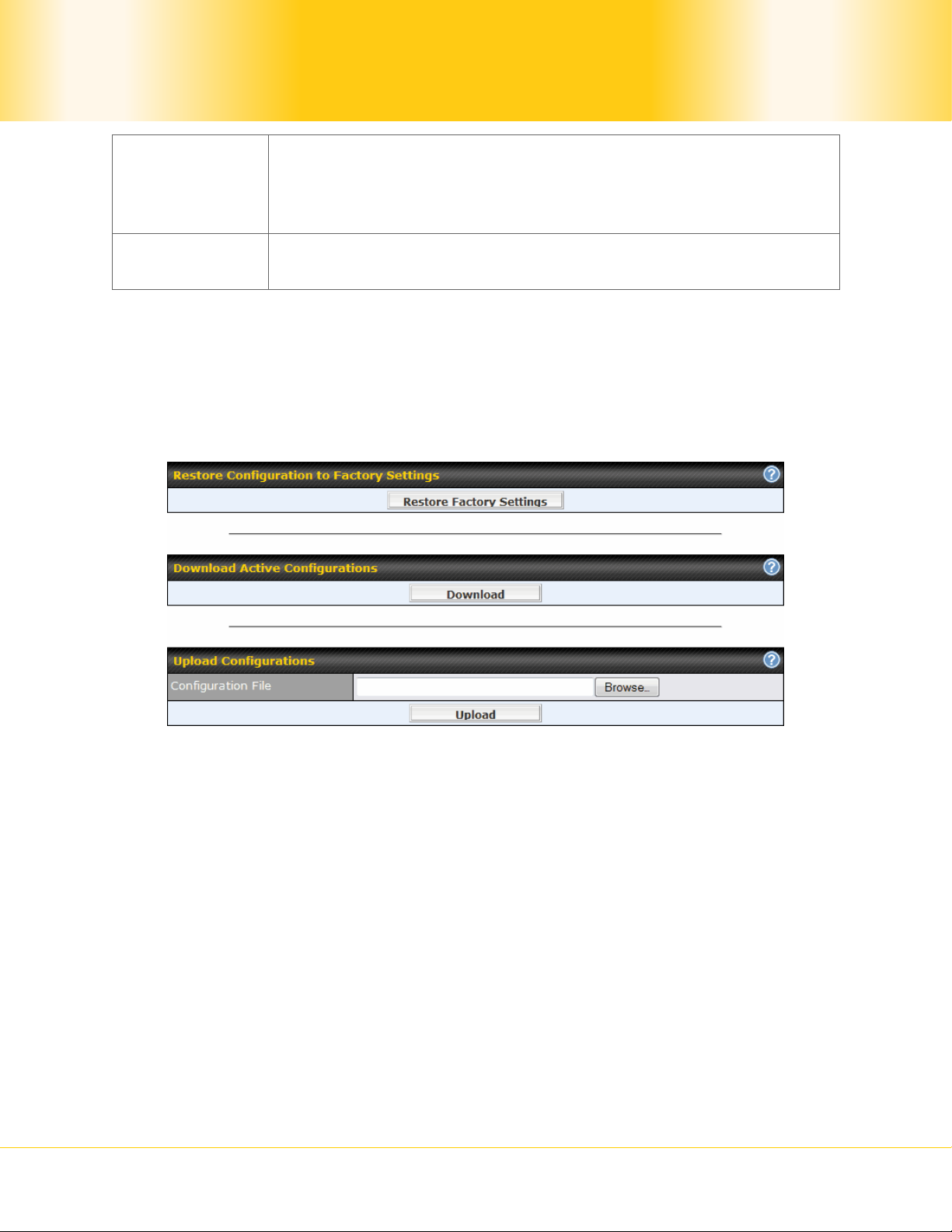
This setting specifies via a drop-down menu the one of the
Privacy
Protocol
following valid privacy protocols:
NONE
DES
Privacy
Password
This setting specifies the privacy password, and is applicable only if
the DES privacy protocol is selected.
19.7 Saving and Loading Configurations
Backing up the Pepwave MAX settings immediately after successful completion of the initial
setup is strongly recommended.
The functionality to download and upload Pepwave MAX settings is found at System >
Configuration:
19.7.1 Restore Configuration to Factory Settings
The Restore Factory Settings button is to reset the configuration to the factory default
settings. You have to click the Apply Changes button to make the settings effective.
19.7.2 Downloading Active Configurations
The Download button is to backup the current active settings. Click Download and save
the configuration file.
19.7.3 Uploading Configurations
To restore or change settings based on a configuration file, click Browse to locate the
configuration file on the local computer, and then click Upload.
The new settings can then be applied by clicking the Apply Changes button on the page
header, or discard at the Main page of Web Administration Interface.
Pepwave MAX Mobile Router
- 65 -
Copyright © 2009 Pepwave

19.8 Flash Management
The Pepwave MAX is equipped with dual flash memory modules. Each flash memory stores
one firmware image. It does not only allow improved flexibility but also facilitates more
effective management of the flash contents. It is possible to upgrade the firmware on the
module/partition that is not designated for booting, so that the boot flash is unaffected by
firmware upgrade process or any potential power failures throughout.
Flash module management is located at System > Flash Management:
Flash Management
Firmware
Version
Flash Status This shows the status of the flash module.
Boot from…
Next
Firmware
Upgrade
Target
The configuration parameters will be applied upon clicking Apply Changes on the page
header of Web Administration Interface.
This displays the firmware version on each flash module/partition
(i.e. Flash 1 or Flash 2)
The star indicates the flash module/partition from which Pepwave
MAX will perform its next boot.
The star indicates the flash module that is the target of the next
firmware upgrade.
By default, the target of the next firmware upgrade is the flash
module that is NOT designated for the next boot.
19.9 Reboot
This page provides a Reboot button for restarting the system.
19.10 Ping Test
Pepwave MAX Mobile Router
- 66 -
Copyright © 2009 Pepwave
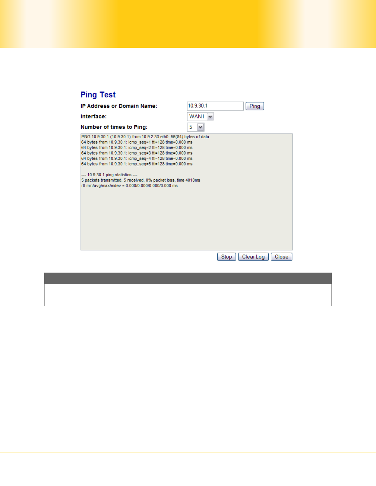
The Ping Test tool in Pepwave MAX performs Pings through a specified Ethernet interface.
The Ping utility is located at System > Tools > Ping. The Ping utility is displayed as a
pop-up window, illustrated as follows:
Tip
A System Administrator can use the Ping utility to manu ally check the connectiv ity of a
particular LAN/WAN connection.
19.11 Traceroute Test
The Traceroute Test tool in Pepwave MAX traces the routing path to the destination through
a particular Ethernet interface.
The Traceroute Test utility is located at System > Tools > Traceroute. The Traceroute
Test utility is displayed as a pop-up window, illustrated as follow s :
Pepwave MAX Mobile Router
- 67 -
Copyright © 2009 Pepwave
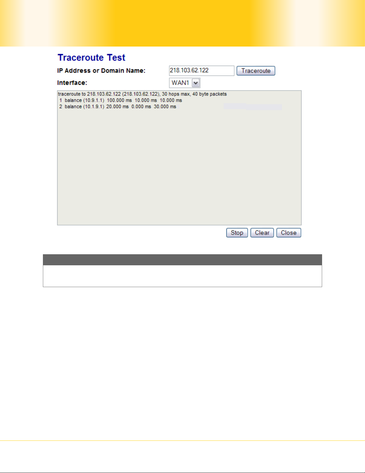
Tip
A System Administrator can use the Traceroute utility to analyze the con nection path
of a LAN/WAN connection.
Pepwave MAX Mobile Router
- 68 -
Copyright © 2009 Pepwave
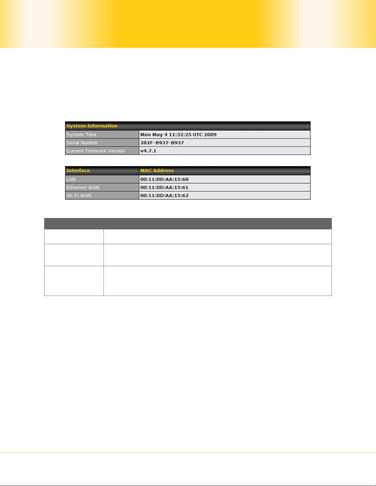
20 Status
The information section displays the information of Pepwave MAX on the Device, Link
Usage, Active Sessions, DHCP Clients, and Event Log.
20.1 Device
System information is located at Status > Device:
System Information
System Time This shows the current system time.
Serial
Number
Current
Firmware
Version
The second table shows the MAC address of each Ethernet interface.
This shows the serial number of the Pepwave MAX unit.
This shows the firmware version that the Pepwave MA X unit is
currently running.
Pepwave MAX Mobile Router
- 69 -
Copyright © 2009 Pepwave
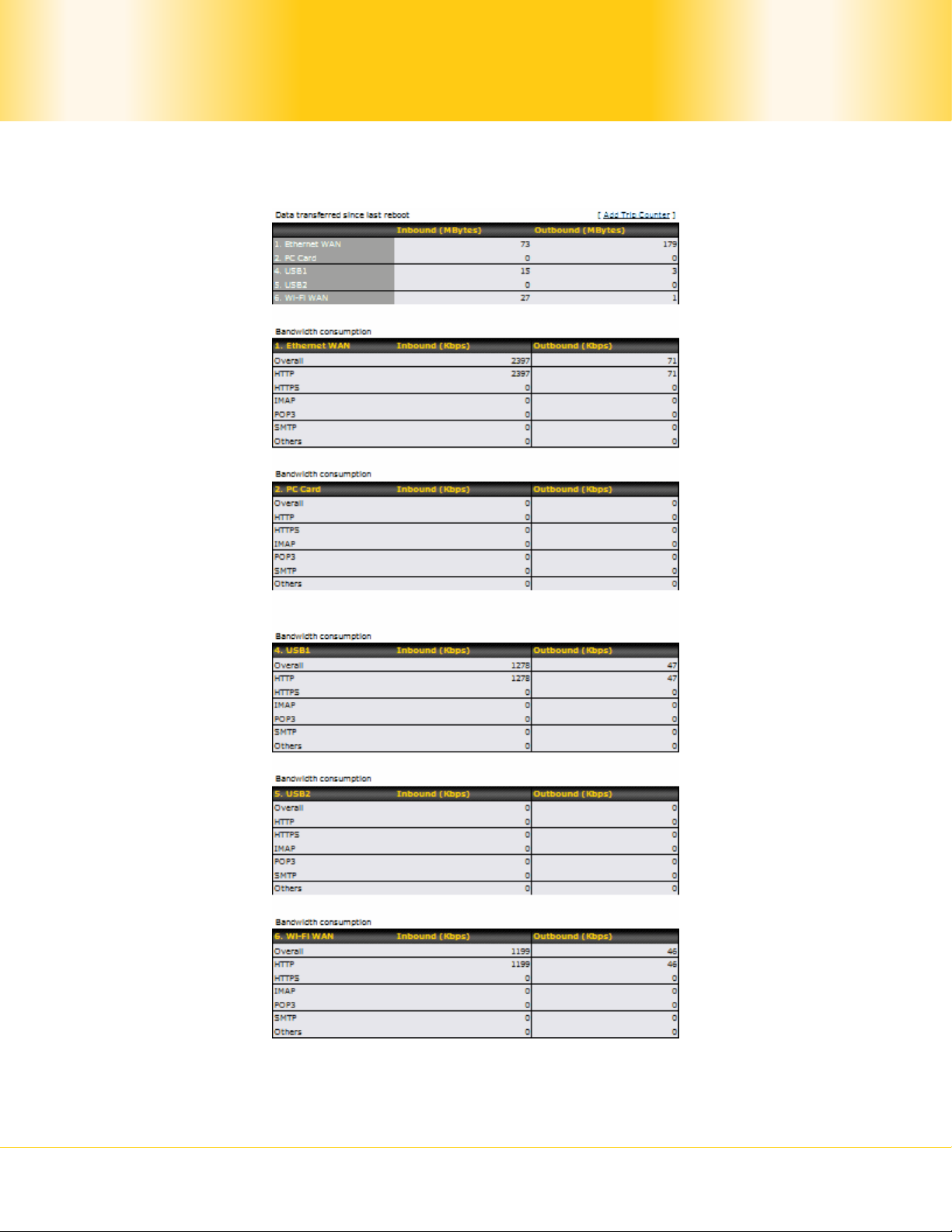
20.2 Link Usage Status
Link usage status information is located at Status > Link Usage:
The Link Usage Status section displays the cumulative amounts of data that have been
transferred through each WAN connection, as well as the inbound and outbound rate of data
transferred via various protocols.
Pepwave MAX Mobile Router
- 70 -
Copyright © 2009 Pepwave
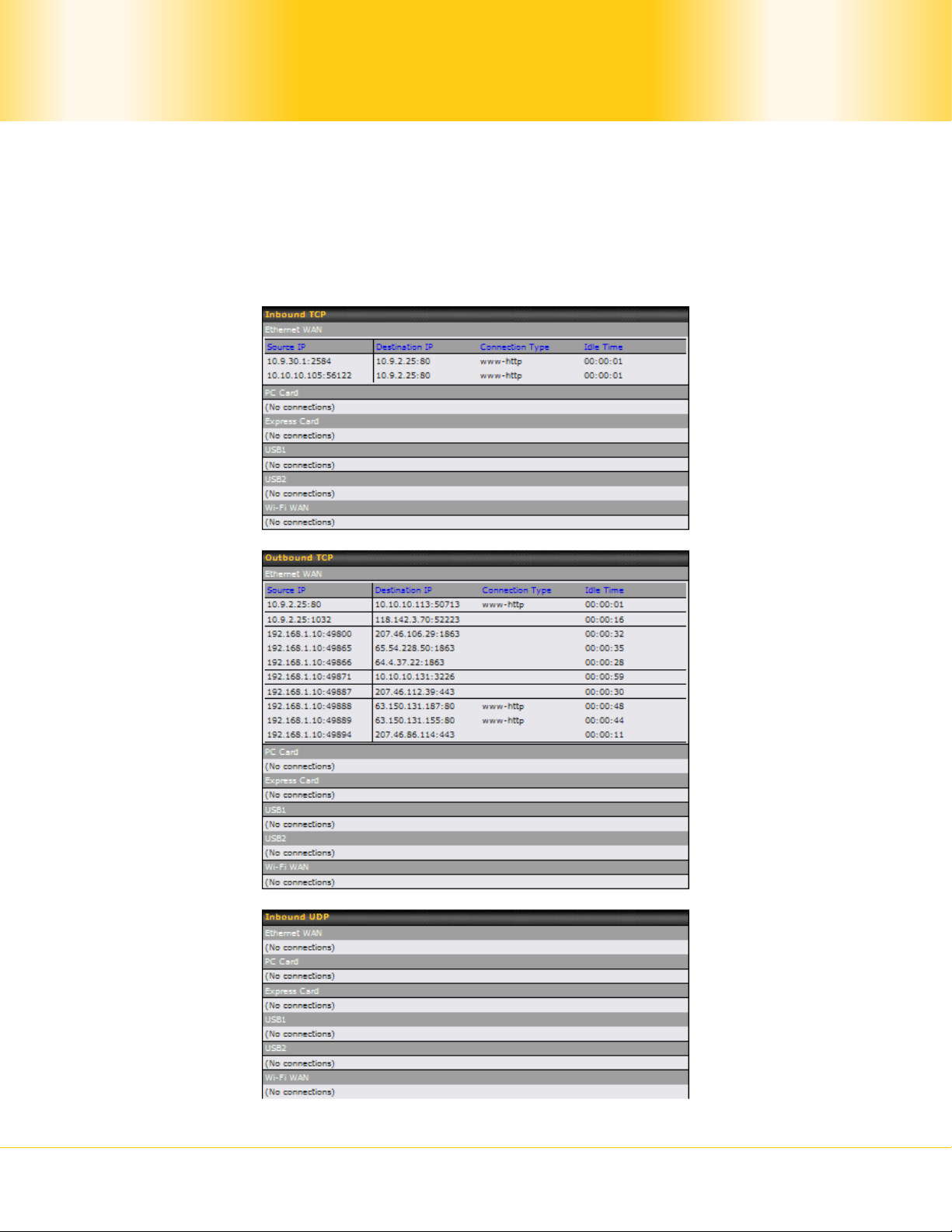
If you click on the Add Trip Counter link, a new transfer volume table will be shown where
the values are reset to zero. This will enable you to coun t the transferred volume from a
specific time instead of from the system up time.
20.3 Active Sessions
Information on Active Sessions is at Status > Active Sessions:
Pepwave MAX Mobile Router
- 71 -
Copyright © 2009 Pepwave
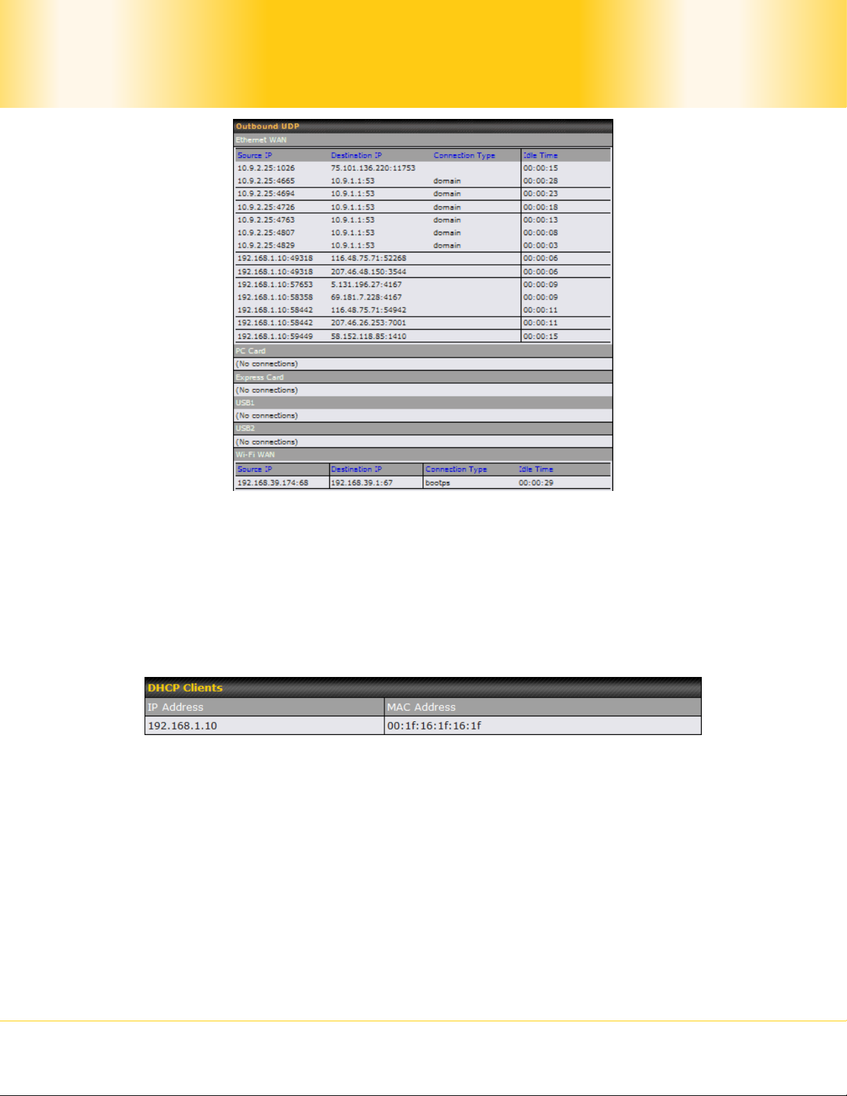
This Active Sessions section displays the active inbound and outbound, UDP and TCP
sessions of each WAN connection on Pepwave MAX.
20.4 DHCP Clients
The DHCP Clients table is located at Status > DHCP Clients. It lists DHCP client IP
addresses and MAC addresses that the Pepwave MAX has offered IP addresses to since it is
powered up.
20.5 Event Log
Event Log information is located at Status > Event Log:
Pepwave MAX Mobile Router
- 72 -
Copyright © 2009 Pepwave

The log section displays a list of events that has taken place on the Pepwave MAX unit.
Click the Refresh button to retrieve log entries again. Click the Clear Log button to clear
the log. Select 50, 100, or all to show the corresponding number of events in the log.
Pepwave MAX Mobile Router
- 73 -
Copyright © 2009 Pepwave

Warning: two antennas must be separated by at lest 20 cm
Appendix A. Restoration of Factory Defaults
To restore the factory default settings on a Pepwave MAX unit, perform the following:
5. Locate the reset button on the Pepwave MAX unit.
6. With a paper clip, press and keep the reset button pressed for at least 10 seconds,
until the unit reboots itself.
Afterwards, the factory default settings will be restored.
Important Note
All user settings will be lost after restoring the factory default settings.
Regular backup of configuration parameters is strongly recommended.
Pepwave MAX Mobile Router
- 74 -
Copyright © 2009 Pepwave

Appendix B. Product Specifications
B.1 Pepwave MAX Mobile Router
Routing
NAT
Flexible Custom Outbound Rout ing Policy
WAN Support
DHCP, Static IP, and PPPoE
Outbound Link Load Balance
Device Management
Wizard & Menu Driven Web Management Interface over HTTP / HTTPS
Remote Reporting and Management
Configurations Upload and Download
Internet Access Sharing
SUA (Single User Account) / Multi-to-Multi NAT
NAT supports PAT (Port Address Translation)
Security
Rules-based Stateful Firewall, with IP, Protocol, and Port filtering
VPN Encryption: 256-bit AES
Intrusion Detection System
Physical Interface
One RJ-45 for an IEEE 802.3u 10/100M WAN
One PC Card Slot
One ExpressCard Slot
Two USB Ports
One Wi-Fi WAN Connector
One Wi-Fi AP Connector for LAN
Four RJ-45 for an IEEE 802.3u 10/100M LAN
Power Specification
AV Input 100-240V, DC Output 9-30V
Operating Environment
Temperature: 0°C - 50°C
Humidity: 10% - 90% (non-condensing)
Pepwave MAX Mobile Router
- 75 -
Copyright © 2009 Pepwave

FCC Statement:
This device complies with Part 15 of the FCC Rules. Operation is subject to the following two
conditions:
(1) this device may not cause harmful interference, and
(2) this device must accept any interference received, including interference that may cause
undesired operation.
Changes or modifications not expressly approved by the party responsible for compliance could
void the user's authority to operate the equipment.
NOTE:
This equipment has been tested and found to comply with the limits for a Class B digital device,
pursuant to Part 15 of the FCC Rules.
These limits are designed to provide reasonable protection against harmful interference in a
residential installation. This equipment generates, uses and can radiate radio frequency energy
and, if not installed and used in accordance with the instructions, may cause harmful interference
to radio communications. However, there is no guarantee that interference will not occur in a
particular installation. If this equipment does cause harmful interference to radio or television
reception, which can be determined by turning the equipment off and on, the user is encouraged
to try to correct the interference by one or more of the following measures:
-- Reorient or relocate the receiving antenna. -- Increase the separation between the equipment
and receiver.
-- Connect the equipment into an outlet on a circuit different from that to which the receiver is
connected.
-- Consult the dealer or an experienced radio/TV technician for help.
Pepwave MAX Mobile Router
- 76 -
Copyright © 2009 Pepwave

Contact Us:
Sales
sales@pepwave.com
Support
support@pepwave.com
Business Development and
Partnerships
partners@pepwave.com
www.pepwave.com
Address:
United States Office
800 West El Camino Real,
Mountain View
CA 94040
United States
Tel: +1 (650) 450 9669
Fax: +1 (866) 625 4664
Hong Kong Office
17/F, Park Building,
476 Castle Peak Road
Cheung Sha Wan
Hong Kong
Tel: +852 2990 7600
Fax: +852 3007 0588
.
 Loading...