

Page 1
Page 2

Copyright © 2007 Pirelli Broadband Solutions S.p.A. All rights reserved. This document contains Pirelli proprietary and
confidential information. No part of this document may be copied, reprinted or reproduced in any material form or electronically, whether wholly or in part, and no information contained herein may be used or disclosed to third parties unless
under a previous written agreement with Pirelli Broadband Solutions S.p.A setting forth relevant terms and conditions.
Trademarks:
All terms used in this document that are known to be trademarks or service marks have been noted as such. Pirelli cannot attest to the accuracy of this information. Other product and corporate names used in this document that may be
trademarks or service marks of other companies are used only for explanation and to the owner’s benefit, without intent
to infringe. Use of a term in this document should not be regarded as affecting the validity of any trademark or service
mark.
This publication is subject to change without notice. Pirelli reserves the right to make changes to equipment design and
system components as well as system documentation and literature as progress in engineering, manufacturing methods,
or other circumstances may warrant.
This publication is intended solely for informational and instructional purposes. Refer to the above as to its possible uses.
It constitutes neither a contract with the user hereof nor a warranty or guarantee with regard to any of the Pirelli products
described herein nor shall it be construed to grant a license or any other rights under any proprietary rights to information
or material included herein. Pirelli hereby expressly disclaims any warranty or guarantee, whether express or implied,
with regard to items described herein. Any contract, license, or warranty between Pirelli and the user hereof is created
solely by separate legal documents.
Manual Code: OGU 930500275-A1
Page 3

CONTENTS
Welcome 1
About this Guide 1
Naming Convention 1
Conventions 1
Introduction 3
Introduction 3
Package Contents 3
Router Advantages 6
Minimum System and Component Requirements 7
Front Panel 7
Rear Panel 9
PRG AV4202N
Hardware Installation 11
Introduction 11
Positioning the Router 11
Installing Micro Filters 12
Powering up the router 13
Connecting the Router 13
Setting Up Your Computer 19
INSTALL Software 19
Ethernet Connection 20
Ethernet Connection >> TCP/IP Protocol Installation 20
Ethernet Connection >> MS Windows 98SE, ME, 2000 20
Ethernet Connection >> MS Windows XP 22
Ethernet Connection >> MAC OS 10.X 23
USB Connection 24
USB Connection >> MS Windows 25
USB Connection >> MAC OS 10.x 25
Wi-Fi connection 25
Router Configuration 27
Introduction 27
© (2007) Pirelli Broadband Solutions S.p.A. All Rights Reserved. Proprietary Use Pursuant to Cover Page Instructions.
OGU 930500275-A1 i
Page 4

PRG AV4202N
Installation Wizard Section 31
Log In Setup 32
Test Ethernet Link 33
Analyze internet connection Type 33
Setup internet Connection 33
Test service Provider Connection 33
Test Internet Connection 33
Wireless Setup 33
VoIP Setup 34
Installation Completed 34
Quick Setup Section 35
Point-to-point protocol over Ethernet (PPPoE) over ATM 36
Ethernet (PPPoE) over PTM 36
Point-to-point protocol over ATM (PPPoA) 37
Routed Ethernet Connection over ATM (ETHoA) 37
Routed Ethernet Connection over PTM (ETHoP) 37
Bridged Ethernet Connection over ATM (ETHoA) 38
Bridged Ethernet Connection over PTM (ETHoP) 38
No Internet Connection 38
Wireless 38
Administrator 38
Network Connections Section 39
LAN Bridge 40
LAN Bridge >> General 40
LAN Bridge >> Settings 41
LAN Bridge >> Routing 44
LAN Bridge >> Bridging 46
LAN Bridge >> Advanced 47
LAN Ethernet 47
LAN Ethernet >> General 47
LAN Ethernet >> Settings 48
LAN Ethernet >> Advanced 49
LAN Wireless 802.11n Access Point 50
LAN Wireless 802.11nn Access Point >> General 50
LAN Wireless 802.11n Access Point >> Settings 51
LAN Wireless 802.11n Access Point >> Wireless 52
LAN Wireless 802.11n Access Point >> Advanced 57
WAN DSL 57
© (2007) Pirelli Broadband Solutions S.p.A. All Rights Reserved. Proprietary Use Pursuant to Cover Page Instructions.
ii OGU 930500275-A1
Page 5

PRG AV4202N
WAN DSL >> General 58
WAN DSL >> Settings 58
Security Section 61
General 62
Access Control 64
Port Forwarding 65
DMZ Host 68
Port Triggering 69
Web Site Restrictions 69
NAT 70
Connections 71
Advanced Filtering 72
Security Log 73
Voice over IP Section 75
Line Settings 75
Speed Dial 76
Monitoring 77
Advanced 78
Parental Control Section 81
general overview 82
filtering policy 83
advanced options 85
statistics 86
QoS Section 87
General 87
Traffic Priority 89
Traffic Shaping 92
DSCP Settings 93
802.1p Settings 95
Class Statistics 96
Advanced Section 99
About PRG AV4202N 100
Backup and Restore 101
Certificates 103
© (2007) Pirelli Broadband Solutions S.p.A. All Rights Reserved. Proprietary Use Pursuant to Cover Page Instructions.
OGU 930500275-A1 iii
Page 6

PRG AV4202N
Configuration File 104
DDNS 105
DNS Server 106
PRG AV4202N Firmware Upgrade 107
Date and Time 109
Diagnostics 110
Disk Management 112
ftp server 113
File Server 113
IP Address Distribution 114
ipsec 116
l2tp server 117
MAC Cloning 118
media sharing 119
Network Objects 120
pptp server 121
PPPoE Relay 122
Print Server 122
Protocols 123
RADIUS 124
Reboot 125
Remote Administration 125
Restore Defaults 128
Routing 128
SSH 130
ssl vpn 131
Scheduler Rules 133
Simple network management protocol 134
system log 136
System Settings 137
umts 140
Universal Plug and Play 140
Users 141
WINS Server 143
Wake Up on LAN 144
Web Server 144
System Monitoring Section 148
Network Connections 148
System Log 149
CPU 150
© (2007) Pirelli Broadband Solutions S.p.A. All Rights Reserved. Proprietary Use Pursuant to Cover Page Instructions.
iv OGU 930500275-A1
Page 7

PRG AV4202N
Troubleshooting 153
Basic Connection Checks 153
Browsing to the Router Configuration Screens 153
Connecting to the Internet 154
Forgotten Password and Reset to Factory Defaults 154
Wireless Networking 155
Frequently Asked Questions 156
Safety Information 157
IP Addressing 159
Technical Specifications 161
Glossary 167
© (2007) Pirelli Broadband Solutions S.p.A. All Rights Reserved. Proprietary Use Pursuant to Cover Page Instructions.
OGU 930500275-A1 v
Page 8

ABOUT THIS GUIDE
NAMING CONVENTION
CONVENTIONS
Welcome
This guide describes how to install and configure the PRG AV4202N. This guide
is intended for use by those responsible for installing and setting up network
equipment; consequently, it assumes a basic working knowledge of LANs (Local Area Networks) and Internet Routers.
Throughout this guide, the PRG AV4202N is referred to as the “Wireless
Router”. Category 5 Ethernet Cables are referred to as Ethernet Cables
throughout this guide.
Table 1 and Table 2 list conventions that are used throughout this guide.
TABLE 1. Notice Icons
Icon Notice Type Description
Information note Information that describes important features or instruc-
tions.
© (2007) Pirelli Broadband Solutions S.p.A. All Rights Reserved. Proprietary Use Pursuant to Cover Page Instructions.
Welcome OGU 930500275-A1 1
Welcome
Page 9

PRG AV4202N
TABLE 1. Notice Icons
Icon Notice Type Description
Caution Information that alerts you to potential loss of data or
Warning Information that alerts you to potential personal injury.
TABLE 2. Text Conventions
potential damage to an application, system, or device.
Convention Description
The words “enter” and
“type”
Keyboard key names If you must press two or more keys simultaneously, the key
Words in italics Italics are used to:
When you see the word “enter” in this guide, you must type something, and then press Return or Enter. Do not press Return or Enter when an instruction simply says “type.”
names are linked with a plus sign (+). Example:
Press Ctrl+Alt+Del
Emphasize a point.
Denote a new term at the place where it is defined in the text.
Identify menu names, menu commands, and software button
names. Examples: “From the Help menu, select Contents.
Click OK.”
© (2007) Pirelli Broadband Solutions S.p.A. All Rights Reserved. Proprietary Use Pursuant to Cover Page Instructions.
2 OGU 930500275-A1 Welcome
Page 10

Introduction
INTRODUCTION
Introduction
The PRG AV4202N is designed to provide a cost-effective means of sharing a
single broadband Internet connection between several wired and wireless computers. The Router also provides protection in the form of an electronic “firewall”
preventing anyone outside of your network from seeing your files or damaging
your computers. The Router offers VoIP functionalities through 2 VoIP channels
allowing you to use existing analog phones and a fallback to old telephony at
loss of power, WAN, Internet or VoIP.
The PRG AV4202N is an VDSL2 router, targeted to residential environments
and SOHO customers, that provides routed broadband services from a single
and modular access point.
The PRG AV4202N is the ideal solution for:
1. Connecting multiple PCs and Video game consoles;
2. Sharing broadband internet connections with all home computers;
3. Sharing printers and peripherals;
4. Performing VoIP connections.
PACKAGE CONTENTS
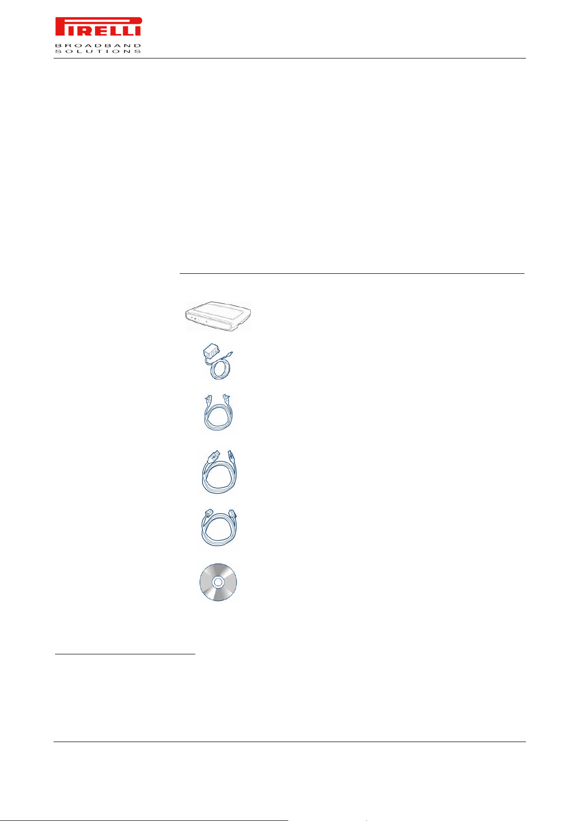
Your new PRG AV4202N VDSL2 Router kit contains the related hardware and
software. In it you will find:
1. One PRG AV4202N unit
2. One Switching Power Supply adapter
3. One micro filter
*
This item may be optional and not included in the package: please check with your Service Provider
© (2007) Pirelli Broadband Solutions S.p.A. All Rights Reserved. Proprietary Use Pursuant to Cover Page Instructions.
Introduction OGU 930500275-A1 3
*
Page 11
PRG AV4202N
4. One USB cable
5. One phone cable RJ-11 plug (RJ-11)
6. One Ethernet CAT5 cable with RJ-45 plug
7. A CD-ROM containing:
a. USB Driver
b. User Manual
c. Quick Installation Guide
d. Smart Setup Configuration Utility
TABLE 1. Kit Material
Quantity DESCRIPTION
1 PRG AV4202N
1 Switching Power Supplier Adapter
†
1 Ethernet Cable
1 USB Cable
1 Phone Cable
1 CD-ROM
†
This item may be optional and not included in the package: please check with your Service Provider
© (2007) Pirelli Broadband Solutions S.p.A. All Rights Reserved. Proprietary Use Pursuant to Cover Page Instructions.
4 OGU 930500275-A1 Introduction
Page 12

PRG AV4202N
TABLE 1. Kit Material
Quantity DESCRIPTION
1 Micro Filter
‡
If any of the items included in the package is damaged, please contact your
Service Provider.
It implements an “always-on” very high bitrate Digital Subscriber Line (2/2+)
connection to the telephone line on the WAN side, as well as several local connectivity technologies on the LAN side:
Four switched 10/100 Base-TX Ethernet ports
One Universal Serial Bus 1.1 (USB) connection to a host PC
One USB 2.0 Host port for external USB peripherals
One USB Device port
§
One IEEE 802.11b/g/n Wireless LAN access point
Two FXS ports to analog phones
One FXO port to wall phone socket
**
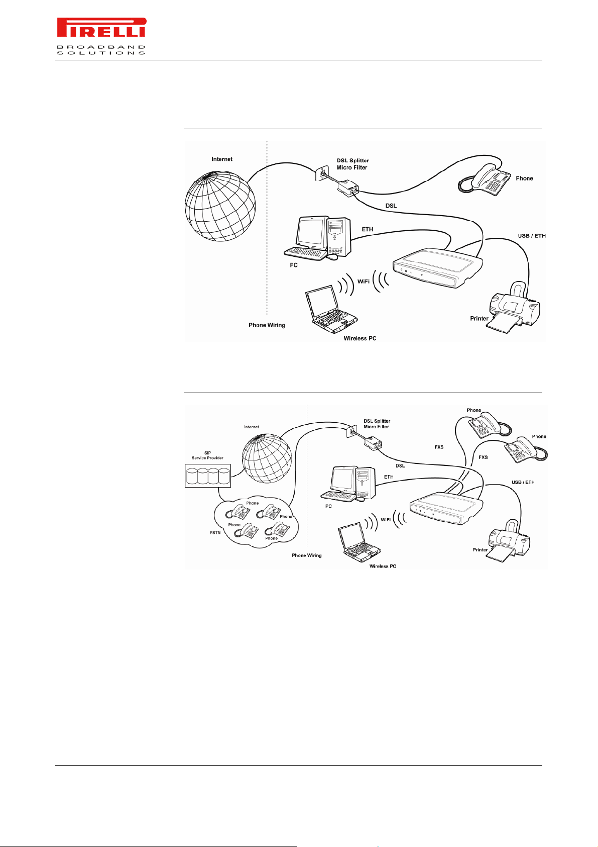
Figure 2 shows a sample network, while in Figure 2 an existing SIP account
case is shown: your Router becomes your connection to the Internet. Connections can be made directly to the Router expanding the number of computers
you can have in your network.
‡
This item may be optional and not included in the package: please check with your Service Provider
§
This port may be optional depending on the product version.
**
This port may be optional depending on the product version.
© (2007) Pirelli Broadband Solutions S.p.A. All Rights Reserved. Proprietary Use Pursuant to Cover Page Instructions.
Introduction OGU 930500275-A1 5
Page 13
PRG AV4202N
FIGURE 1. Sample Home Network
ROUTER ADVANTAGES
FIGURE 2. Sample Home Network (existing SIP account case)
The advantages of the Router include:
Shared Internet connection for both wired and wireless computers
High speed 802.11b/g/n wireless networking
No need for a dedicated, “always on” computer serving as your Internet con-
nection
Cross-platform operation for compatibility with Microsoft® Windows and Ap-
ple® MAC computers (see Technical description for supported platforms).
© (2007) Pirelli Broadband Solutions S.p.A. All Rights Reserved. Proprietary Use Pursuant to Cover Page Instructions.
6 OGU 930500275-A1 Introduction
Page 14

MINIMUM SYSTEM AND
COMPONENT
REQUIREMENTS
PRG AV4202N
Easy-to-use, Web-based setup and configuration
Centralization of all network address settings (DHCP)
a Virtual server to enable remote access to Web, FTP, and other services on
your network
a Security - Firewall protection - against Internet hacker attacks and encryp-
tion to protect wireless network traffic
VoIP functionalities supporting existing analog phones
Communication fallback of to analog lines in case of power or hardware
faults (if supported by your network operator)
a multi-language GUI.
Your Router requires the computer(s) and components in your network to be
configured with at least the following:
A computer with the Operating Systems that support TCP/IP networking pro-
tocols: Microsoft® Windows 98SE, Windows ME, Windows 2000, Windows
XP 32bit or Apple® MAC 10.x
An Ethernet 10Mbps or 10/100 Mbps NIC for each computer to be con-
nected to one of the four Ethernet ports on the rear of the Router
An USB 2.0 port
As optional, an 802.11b/g/n wireless NIC
At least, 60MB of free hard disk space
At least, 128 MB of RAM
Supported Browsers: Internet Explorer 5.5 or higher, Netscape 4.7 or higher
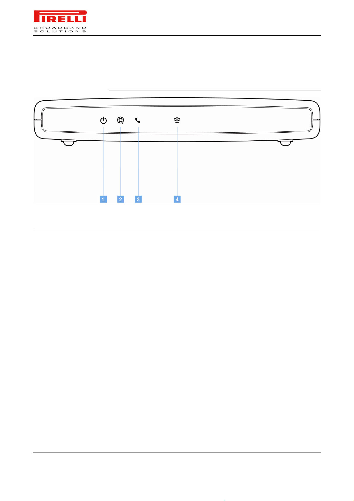
FRONT PANEL
The front panel of the Router contains seven indicator lights (LEDs) that help to
describe the state of networking and connection operations.
© (2007) Pirelli Broadband Solutions S.p.A. All Rights Reserved. Proprietary Use Pursuant to Cover Page Instructions.
Introduction OGU 930500275-A1 7
Page 15
PRG AV4202N
white and Red
FIGURE 3. Front Panel LEDs
TABLE 2. LED Description
Ref. LED LED Color LED Description
1 Power White/Red
2 Internet
activity
3 Phone White/Red
4 Wireless
White/Red
Blue
LAN
Solid White Power on
Solid Red Boot Loader Failure
Off –
Solid Green WAN IP address available (e.g. PPP active)
Blinking Green IP connected and IP traffic is passing through device (either direction)
Solid Red WAN IP address not available (e.g. PPP failure)
Off Modem power off or the modem is in bridged mode or connection not pre-
On One of the FXS port has been registered with a SIP proxy server
Blinking One of the telephones connected to the FXS port is off-hook
Off Modem power off on phone line 1 or phone line 2 not registered
On Wireless functionality enabled
Blinking Wireless LAN activity present (traffic in either direction)
Off Wireless functionality disabled
Power off
sent
© (2007) Pirelli Broadband Solutions S.p.A. All Rights Reserved. Proprietary Use Pursuant to Cover Page Instructions.
8 OGU 930500275-A1 Introduction
Page 16
REAR PANEL
PRG AV4202N
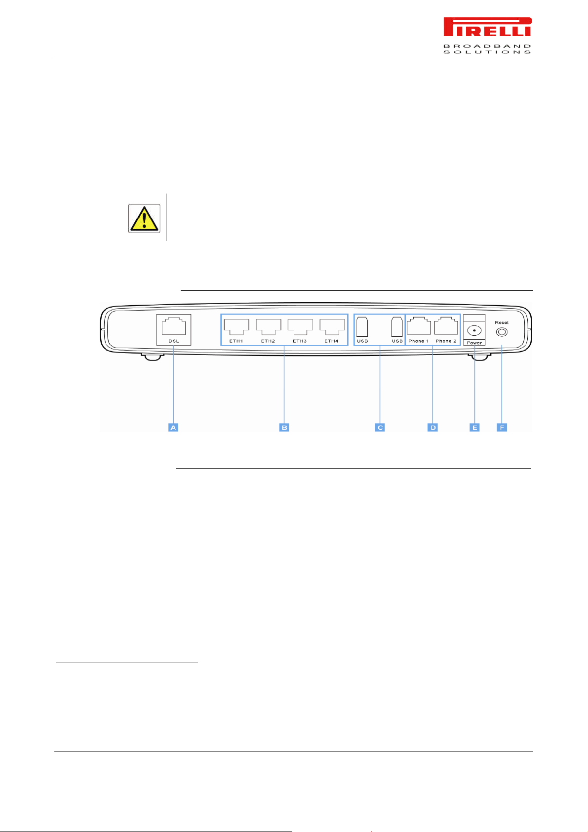
The rear panel of the Router contains a reset button, a power adapter socket,
four LAN ports, one port, one USB device port,††two USB Host port, one FXO
port‡‡, two FXS ports and one Wi-Fi REG button.
Do not force the antenna beyond its mechanical stops. Rotating the antenna further may cause damage.
FIGURE 4. Rear Panel Ports
PORT DESCRIPTION
A PhoneDSL connector (2/2+)
B port Four Ethernet ports 10/100 Mbps
C ports USB 2.0 Host ports
D FXS
E Power connector
F Power button
- Reset to factory default button (located on the side of the device)
Optional FXO
††
This port may be optional depending on the product version.
‡‡
This port may be optional depending on the product version.
© (2007) Pirelli Broadband Solutions S.p.A. All Rights Reserved. Proprietary Use Pursuant to Cover Page Instructions.
TABLE 3. Port Description
Introduction OGU 930500275-A1 9
Page 17

PRG AV4202N
© (2007) Pirelli Broadband Solutions S.p.A. All Rights Reserved. Proprietary Use Pursuant to Cover Page Instructions.
10 OGU 930500275-A1 Introduction
Page 18

INTRODUCTION
Hardware
Installation
This chapter will guide you through a basic installation of the Router including:
1. Positioning the PRG AV4202N
2. Installing Micro Filters
3. Connecting the Router to your network
4. Setting up your computer for networking with the Router
Please read carefully the Safety Information in Appendix “A”
POSITIONING THE ROUTER
You should place the Router in such a location to ensure that:
It is located near an electrical outlet and a phone wall socket
Water or moisture cannot enter the case of the unit
It is out of direct sunlight and away from sources of heat
The cabling is away from power lines, fluorescent lighting fixtures, and
sources of electrical noise such as radios, transmitters and broadband amplifiers.
It is centrally located with respect to the wireless devices that will be con-
nected to the Router. A suitable location might be on top of a high shelf to
ensure the maximum coverage for all connected devices.
© (2007) Pirelli Broadband Solutions S.p.A. All Rights Reserved. Proprietary Use Pursuant to Cover Page Instructions.
Hardware Installation OGU 930500275-A1 11
Hardware Installation
Page 19
INSTALLING MICRO
FILTERS
PRG AV4202N
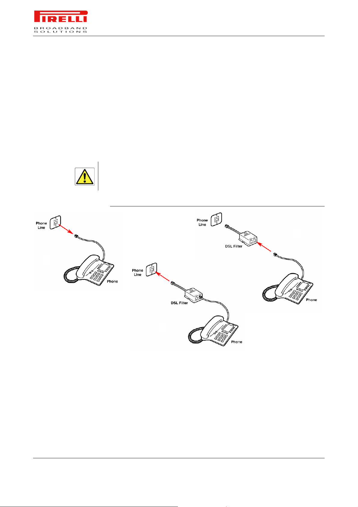
Before beginning installation you must locate devices in your house requiring a
DSL filter such as phones, fax machines, answering machines, dial-up modems, Satellite TV dialers or monitored security systems and attach a DSL filter
to any one of them sharing the same phone line as your DSL modem.
To install DSL filters please follow these steps:
1. Disconnect the phone cable from the telephone wall socket
2. Insert the phone cable into the DSL filter port identified with a phone symbol
3. Insert the DSL filter cable into the telephone wall socket
You do not need to attach a DSL filter to unused wall sockets.
FIGURE 1. Micro Filter Installation
1
2
3
© (2007) Pirelli Broadband Solutions S.p.A. All Rights Reserved. Proprietary Use Pursuant to Cover Page Instructions.
12 OGU 930500275-A1 Hardware Installation
Page 20
POWERING UP THE
ROUTER
CONNECTING THE
ROUTER
PRG AV4202N
To power up the Router:
1. Plug the power adapter into the power adapter port located on the rear of
the Router
2. Plug the power adapter into a standard electrical wall socket
3. Press the Power button located on the rear panel of the Router
4. Wait for the power LED to turn steady green
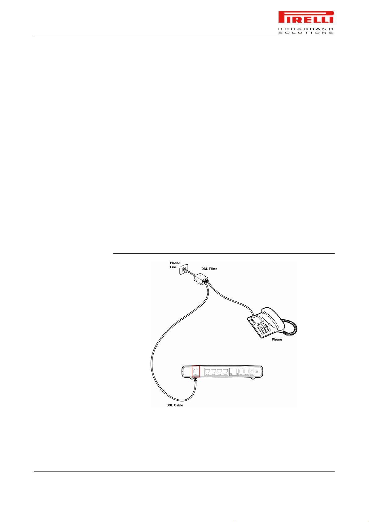
The first step to install the router is to physically connect it to the telephone
socket and then to connect it to a computer by means of an Ethernet or an USB
connection.
To connect the phone cable:
1. Connect one end of the phone cable into the DSL filter port identified with a
computer symbol
2. Connect the other end of the phone cable into the DSL port on the rear of
the Router
FIGURE 2. Phone Cable Connection
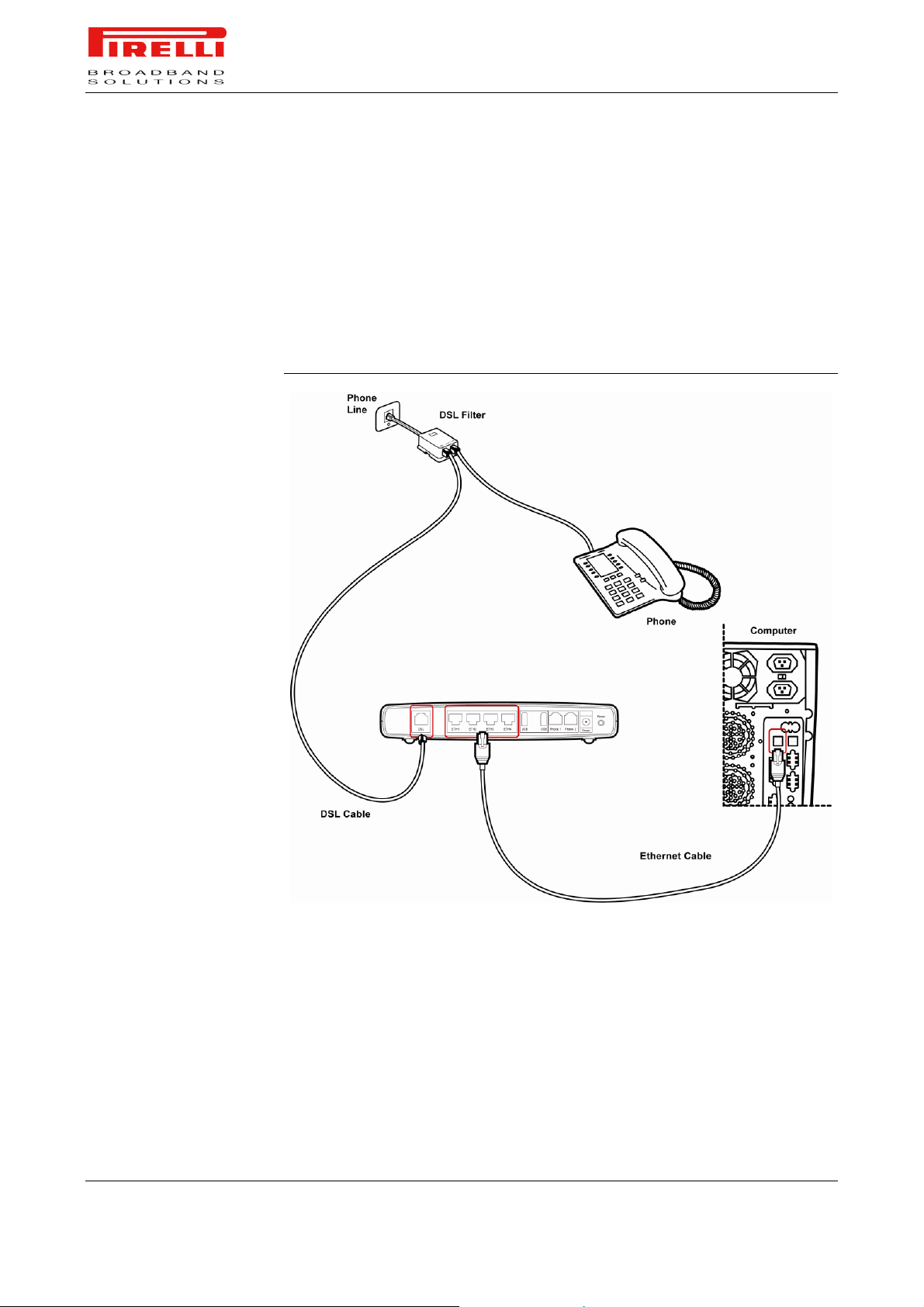
To connect the Ethernet cable:
© (2007) Pirelli Broadband Solutions S.p.A. All Rights Reserved. Proprietary Use Pursuant to Cover Page Instructions.
Hardware Installation OGU 930500275-A1 13
Page 21
PRG AV4202N
1. Connect one end of the Ethernet cable into one of the four Ethernet ports on
the rear of the Router
2. Connect the other end of the Ethernet cable into the Ethernet Network card
of your computer
3. Verify if the Ethernet Network card is configured as DHCP client, otherwise
configure it to remain in the same local network of the router interface (see
chapter “Setting Up Your Computer”)
FIGURE 3. Ethernet Cable Connection
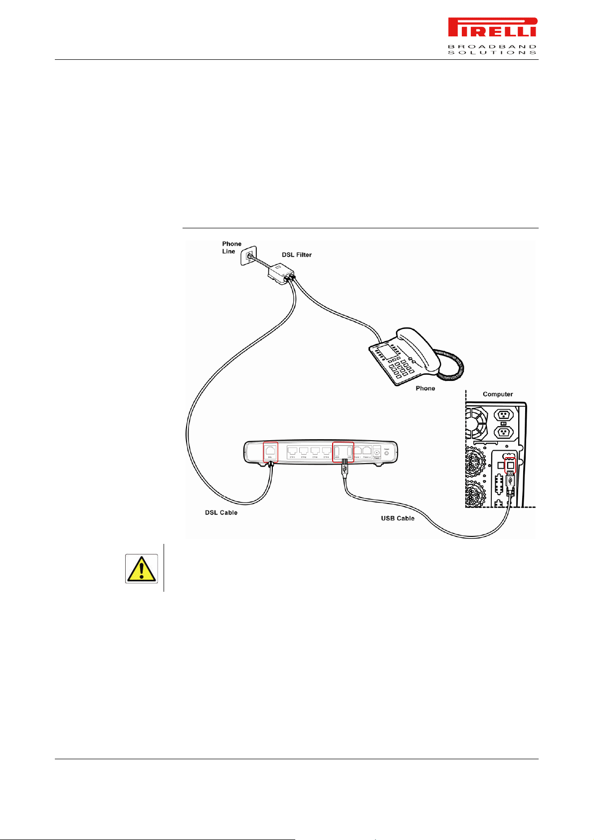
To connect the USB cable, follow the procedure according to your Operating
System:
WINDOWS
1. Connect one end of the USB cable into the USB port of your PC
2. Browse till x:\USB driver folder (where “x” is the CD-ROM drive unit letter);
launch the “setup.exe” executable (“x:\USB driver\setup.exe”) and follow
setup instructions
© (2007) Pirelli Broadband Solutions S.p.A. All Rights Reserved. Proprietary Use Pursuant to Cover Page Instructions.
14 OGU 930500275-A1 Hardware Installation
Page 22
PRG AV4202N
3. The setup software will invite you to plug the other end of the USB cable into
the USB port on the rear of the Router
MAC 10.x
1. Connect one end of the USB cable into the USB port of your PC
2. Connect the other end of the USB cable into the USB port on the rear of the
Router. The Operating System will automatically recognize the device
FIGURE 4. USB Cable Connection
Don’t plug the other end of the USB cable until setup software will ask you to do it.
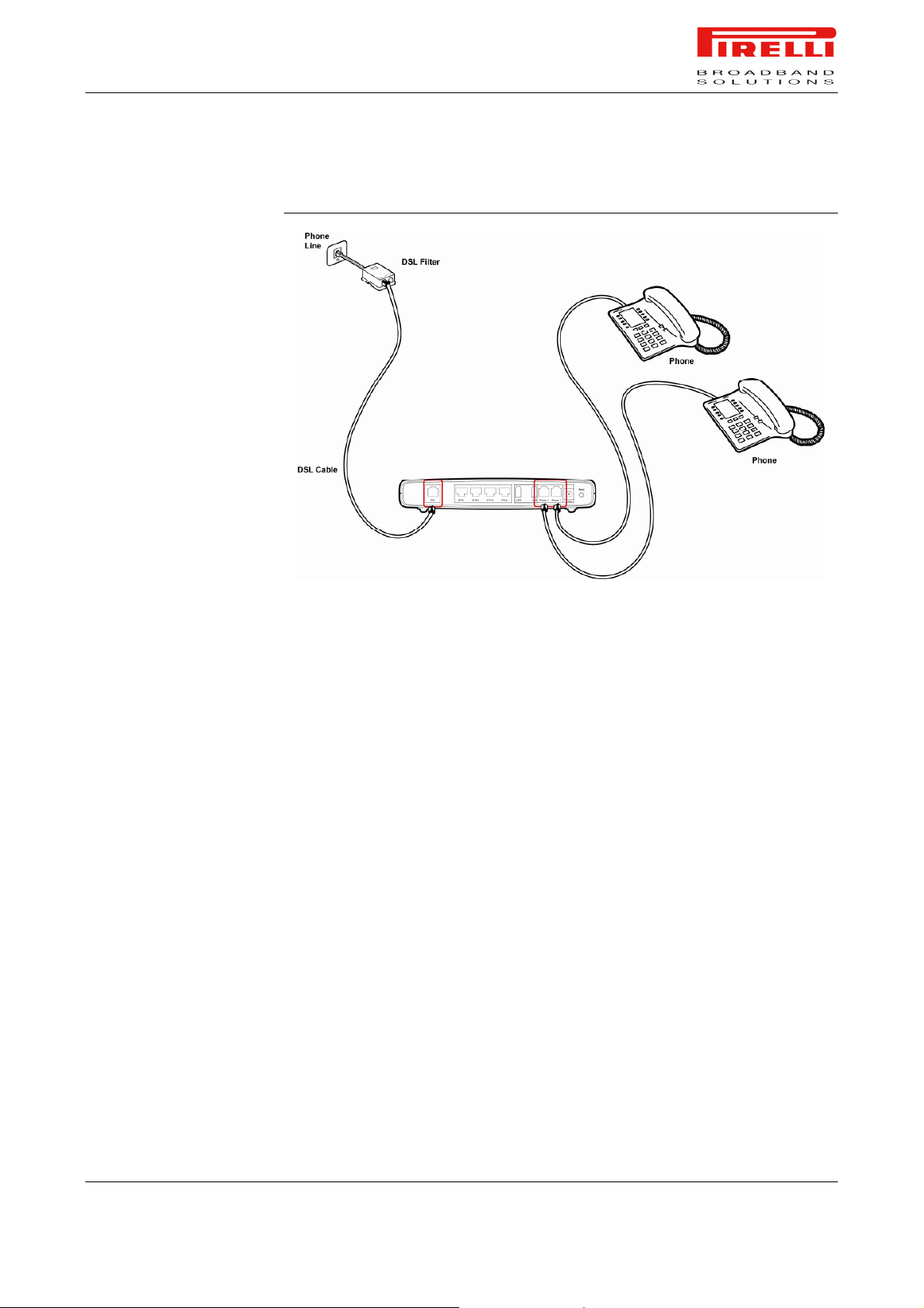
In the case your provider will supply to you a SIP account, it will be needed to
properly connect the FXS and FXO ports. In detail you must follow these steps:
1. Connect one end of the first phone cable into the DSL filter port identified
with a computer symbol
2. Connect the other end of the first phone cable into the DSL port of the
Router
© (2007) Pirelli Broadband Solutions S.p.A. All Rights Reserved. Proprietary Use Pursuant to Cover Page Instructions.
Hardware Installation OGU 930500275-A1 15
Page 23

PRG AV4202N
3. Connect one end of the second phone cable into the DSL filter port identified
with a phone symbol
4. Connect the other end of the second phone cable into the WALL port of the
Router (FXO connection)
5. Connect a maximum of two analog phones to the Phone 1 or Phone 2 ports
*
of the Router (FXS connection)
*
If your product does not include the FXO port, exclude steps 3 and 4
© (2007) Pirelli Broadband Solutions S.p.A. All Rights Reserved. Proprietary Use Pursuant to Cover Page Instructions.
16 OGU 930500275-A1 Hardware Installation
Page 24
PRG AV4202N
FIGURE 5. FXS connections
Connect to your PC with Ethernet or USB cables as described in the previous
steps.
© (2007) Pirelli Broadband Solutions S.p.A. All Rights Reserved. Proprietary Use Pursuant to Cover Page Instructions.
Hardware Installation OGU 930500275-A1 17
Page 25

PRG AV4202N
© (2007) Pirelli Broadband Solutions S.p.A. All Rights Reserved. Proprietary Use Pursuant to Cover Page Instructions.
18 OGU 930500275-A1 Hardware Installation
Page 26

INSTALL SOFTWARE
Setting Up Your
Computer
The Router has the ability to dynamically allocate network addresses to the
computers on your network, using DHCP. However, your computers need to be
configured correctly for this to take place. To change the configuration of your
computers to allow this, follow the instructions in this chapter.
The very first time you set up your computer, we recommend you to use the
Smart Setup Configuration Utility if your ISP has provided you with.
Before installing the PRG AV4202N software please close all applications to avoid any conflict.
This utility offers a guided product tour, a step by step hardware installation
guide, a software installation guide and setup depending on your connection
choice (USB or ETHERNET) and a driven user registration with DSL Internet
connection line check.
Smart Setup Configuration Utility allows, for supported Microsoft® Windows
Operating Systems, to setup automatically your computer Ethernet settings.
To launch it, insert the CD-ROM in CD-ROM unit: if the auto-play function is enabled it will start automatically, otherwise open it manually from “x:”, where x is
your CD-ROM drive letter.
© (2007) Pirelli Broadband Solutions S.p.A. All Rights Reserved. Proprietary Use Pursuant to Cover Page Instructions.
Setting Up Your Computer OGU 930500275-A1 19
Setting Up Your Computer
Page 27

ETHERNET CONNECTION
ETHERNET CONNECTION
>> TCP/IP PROTOCOL
INSTALLATION
PRG AV4202N
In case you already established a connection with your Router a first time
and/or you do need to set up manually a connection to your Router, please follow the instructions described in this chapter. You will be guided to set up an
Ethernet connection to the Router. To do so, first you have to verify the existence of a TCP/IP protocol stack and, then, according to your Operating System, to establish an Ethernet connection to it. This connection will require you to
enable your computer to receive from the Router its own IP Address automatically: in such a case, the Router acts like the DHCP server in your local network.
This procedure requires the TCP/IP protocol installed on your computer. Refer
to the following chapters and to your Microsoft® Windows or Apple® MacOS
10.x operating systems manuals.
Microsoft® Windows 98SE, ME, 2000
1. Put in the CD-ROM drive your Windows installation CD-ROM
2. Starting from Start -> Settings -> Control Panel -> Network Control Panel,
make a double click on the Network icon
3. Select Configuration -> TCP/IP and then click on the Add button
4. Select Protocols, click on Add button and choose Microsoft TCP/IP. Then
click on the OK button
5. After the computer reboots, you're ready to configure the TCP/IP settings
Configure the Network adapter to obtain automatically an IP address
ETHERNET CONNECTION
>> MS WINDOWS 98SE, ME,
2000
© (2007) Pirelli Broadband Solutions S.p.A. All Rights Reserved. Proprietary Use Pursuant to Cover Page Instructions.
Microsoft® Windows XP
1. Put in the CD-ROM drive your Windows installation CD-ROM
2. Starting from Start -> Settings -> Control Panel make a double click on the
Network icon.
3. Select Protocol and click on the Add button. Select Microsoft and TCP/IP,
then click on the OK button.
4. Configure the Network adapter to obtain automatically an IP address.
Apple® MacOS 10.x
TCP/IP is installed on a MacOS system as part of Open Transport.
To configure TCP/IP on these Operating Systems follow these steps:
1. Select Start -> Settings -> Control Panel and make a double click on the
Network icon.
20 OGU 930500275-A1 Setting Up Your Computer
Page 28
PRG AV4202N
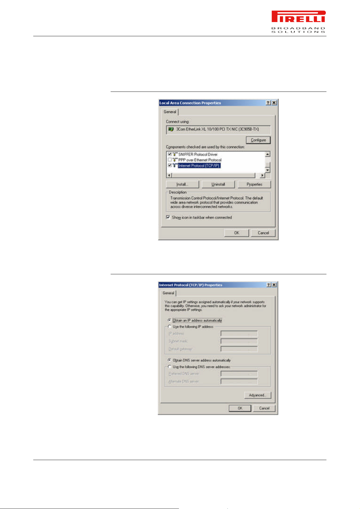
2. Select Configuration ->TCP/IP then click on Properties button.
FIGURE 1. Local Area Connection Properties
3. Select the IP Address Tab, then check to obtain an automatically IP address.
Click on OK button.
FIGURE 2. Internet Protocol (TCP/IP) Properties
© (2007) Pirelli Broadband Solutions S.p.A. All Rights Reserved. Proprietary Use Pursuant to Cover Page Instructions.
Setting Up Your Computer OGU 930500275-A1 21
Page 29
ETHERNET CONNECTION
>> MS WINDOWS XP
PRG AV4202N
4. A system reboot will be required to make the changes real.
5. Enter http://192.168.1.1/ in the address bar of your browser to open the PRG
AV4202N Home Page.
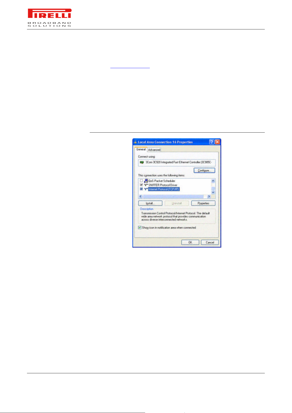
To configure TCP/IP on MS Windows XP Operating System follow these steps:
1. Select Start -> Settings -> Control Panel and make a double click on the
Network icon.
2. Select Protocols ->TCP/IP then click on Properties button.
FIGURE 3. Local Area Connection Properties
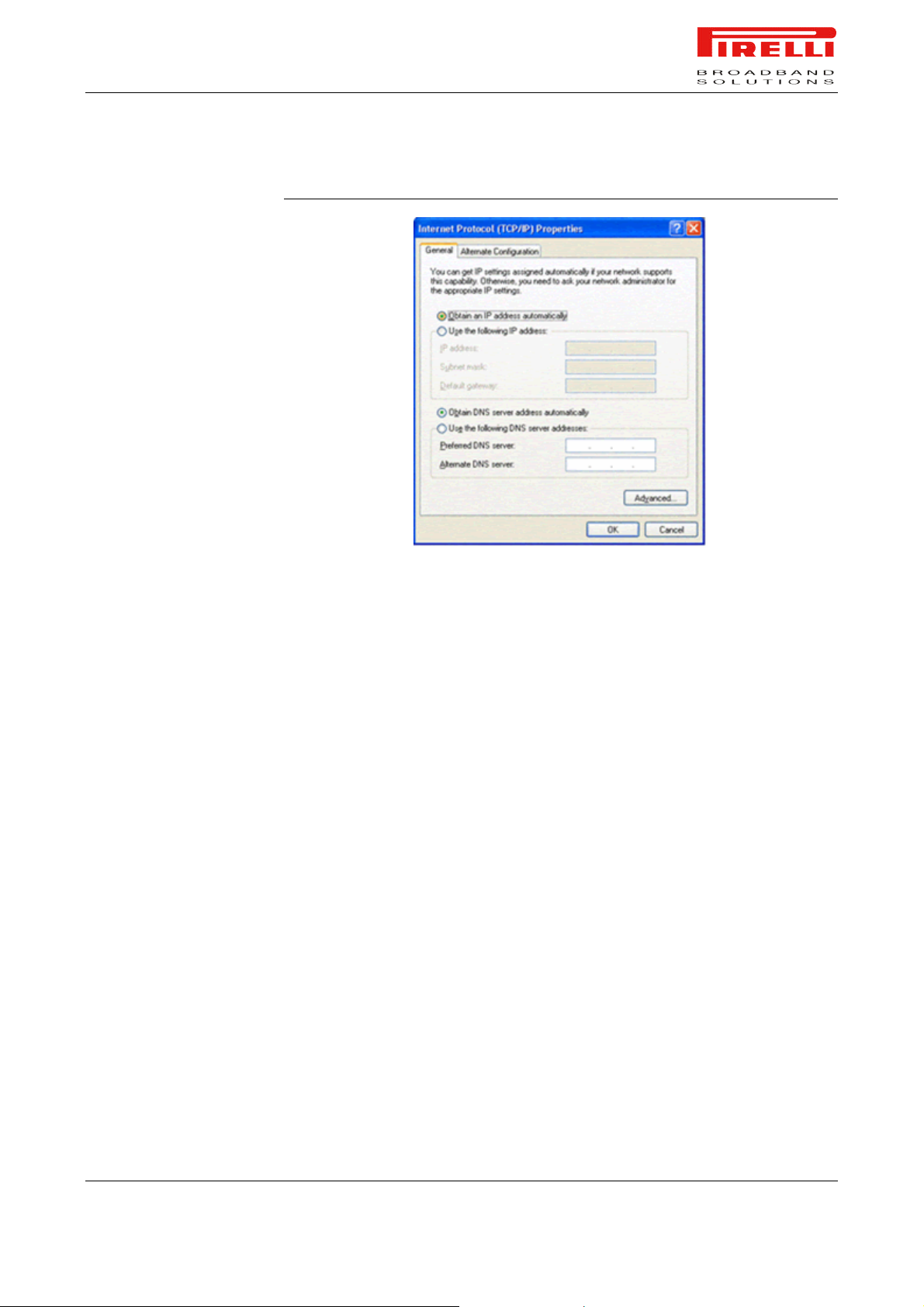
3. Select the General Tab, then check to obtain an automatically IP address.
Click on OK button.
© (2007) Pirelli Broadband Solutions S.p.A. All Rights Reserved. Proprietary Use Pursuant to Cover Page Instructions.
22 OGU 930500275-A1 Setting Up Your Computer
Page 30
PRG AV4202N
FIGURE 4. Internet Protocol (TCP/IP) Properties
ETHERNET CONNECTION
>> MAC OS 10.X
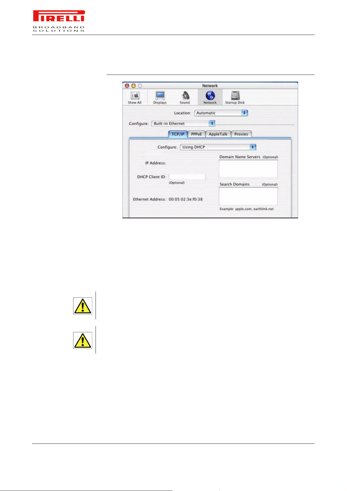
To configure TCP/IP on MAC OS 10.x follow these steps:
1. Open the Apple Menu -> System Preferences and select Network.
2. From the Show drop down list, according to the type of connection used, se-
lect Built-in Ethernet.
3. Select the TCP/IP tab.
4. Select DHCP from the Configure pop-up menu to have a dynamic IP ad-
dress.
© (2007) Pirelli Broadband Solutions S.p.A. All Rights Reserved. Proprietary Use Pursuant to Cover Page Instructions.
Setting Up Your Computer OGU 930500275-A1 23
Page 31
PRG AV4202N
FIGURE 5. Network panel on MAC OS 10.x
USB CONNECTION
5. Click Apply Now.
6. Click on the Register button to save the changes in the Control Panel.
7. Enter http://192.168.1.1/ in the address bar of your browser to open the PRG
AV4202N Home Page.
To connect your first Computer to the PRG AV4202N using USB port, you
have to install the Router’s USB driver on your computer.
Before connecting the USB Cable to the USB Port of the PRG AV4202N you have to run the setup
software and to follow the instructions. Connect the USB Cable only when required from the installation
software.
Only one Windows or Macintosh computer can be directly connected to the PRG AV4202N using the
USB connection. Additional computers can be added to your network using the others connection such
as Ethernet or Wi-Fi.
© (2007) Pirelli Broadband Solutions S.p.A. All Rights Reserved. Proprietary Use Pursuant to Cover Page Instructions.
24 OGU 930500275-A1 Setting Up Your Computer
Page 32
USB CONNECTION >> MS
WINDOWS
USB CONNECTION >> MAC
OS 10.X
PRG AV4202N
Using Windows 98SE the system could require the Operating System installation CD-ROM.
1. Browse the Setup CD-ROM and install the USB Windows driver selecting
the folder x:\driver (where x is the CD-ROM driver unit).
2. Make a double click on setup.exe file to start driver setup procedure.
3. When the message “NOW CONNECT THE USB CABLE” appears, connect
the USB cable from a free USB port of the computer to the PRG AV4202N
USB port.
4. Enter http://192.168.1.1/ in the address bar of your browser to open the PRG
AV4202N Home Page.
As MAC OS 10.x will automatically recognize the device, no USB driver installation is required.
1. Enter http://192.168.1.1/ in the address bar of your browser to open the
PRG AV4202N Home Page.
WI-FI CONNECTION
It requires a computer with 802.11b/g (Wi-Fi Certified) wireless adapter installed.
1. Install your wireless adapter according to the manufacturer’s instructions and
verify that your computer is set to obtain an IP address automatically (DHCP
mode).
You will need to properly configure your adapter to communicate with the PRG AV4202N according
to the configuration rules.
2. In the configuration window of your wireless adapter scan the wireless net-
work (marked with the relevant SSID name) present in your physical environment.
3. Select the SSID of the PRG AV4202N
4. Complete the configuration of the wireless adapter with the same parame-
ters of the PRG AV4202N which are:
RF channel; automatically detect (default = 6)
WEP encryption enable or disable (default = Disable)
WEP key size
© (2007) Pirelli Broadband Solutions S.p.A. All Rights Reserved. Proprietary Use Pursuant to Cover Page Instructions.
Setting Up Your Computer OGU 930500275-A1 25
Page 33

PRG AV4202N
WEP key used
5. To check the connection, connect to the PRG AV4202N Home Page, enter-
ing http://192.168.1.1/ in the address bar of your browser.
© (2007) Pirelli Broadband Solutions S.p.A. All Rights Reserved. Proprietary Use Pursuant to Cover Page Instructions.
26 OGU 930500275-A1 Setting Up Your Computer
Page 34
INTRODUCTION
Router
Configuration
The Router setup program is web based, which means that it is accessed
through your web browser.
To access to Router’s web server:
1. Launch your web browser on the computer
2. Enter the following URL in the location or address field of your browser:
http://192.168.1.1
The Router comes with a default IP address (192.168.1.1). If you change it, please take note of the
new Router’s IP address, otherwise a “Reset to Factory Default” operation should be done to be able
to access again to the Router.
Access to DSL router configuration pages is controlled through user accounts.
The default one is the admin user with unrestricted access to change and view
configuration of the DSL Router.
The default username and password are both set to “admin”. It is recommended to change these default values. Make sure you remember your user name and password, since this is the only way you
will be able to manage your Router
You will be asked to choose the Router interface language between English,
French, Russian, Spanish, Korean, Traditional Chinese, Japanese, German,
Italian and Simplified Chinese and to insert a User Name and a Password: in-
sert them to access to Router’s configuration panels.
© (2007) Pirelli Broadband Solutions S.p.A. All Rights Reserved. Proprietary Use Pursuant to Cover Page Instructions.
Router Configuration OGU 930500275-A1 27
Router Configuration
Page 35

PRG AV4202N
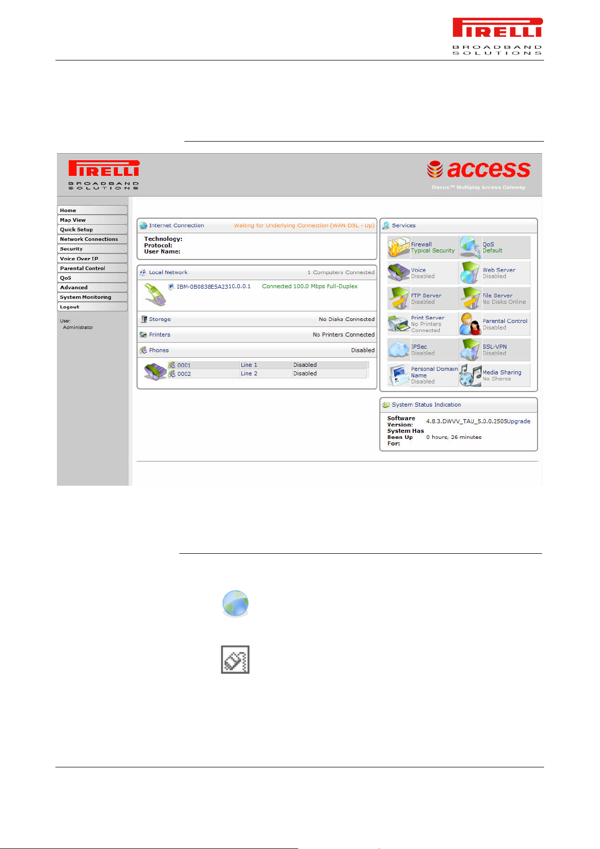
If not already configured, at the first login the Installation Wizard panel will be
shown to configure the Router connection parameters, otherwise the Home
page will be opened as shown in Figure 1.
The Home page contains a menu on the left - always available in all the web
pages which is the starting point for any Router’s configuration.
The complete menu has the following main items:
1. Home: it shows a graphical representation of your network.
2. Map View: it displays the Network Map of attached or configured devices
3. Quick Setup: it allows to quickly perform the Router’s connection setup
4. Network Connections: it shows the status of network connections allowing
to modify them or to create new ones
5. Security: it allows to set security settings
6. Voice over IP: it allows to set VoIP accounts
7. Parental Control: it allows to set Parental Control filtering
8. QoS: it gathers all QoS parameters and settings
9. Advanced: it allows the access to the advanced configuration panels and to
define Router parameters devoted to user access, log management,
Router’s time, Backup Router’s configuration, etc.
10. System Monitoring: a menu to show and run diagnostic test for trouble-
shooting or system behavior analysis and to access to Device Information
and Statistics
11. Logout: to logout from Router’s session.
In order to submit the changes of most of device parameters you have to click the Apply button to save
permanently your changes. In some case a Router’s reboot is required.
© (2007) Pirelli Broadband Solutions S.p.A. All Rights Reserved. Proprietary Use Pursuant to Cover Page Instructions.
28 OGU 930500275-A1 Router Configuration
Page 36
PRG AV4202N
FIGURE 1. Router’s Home Page
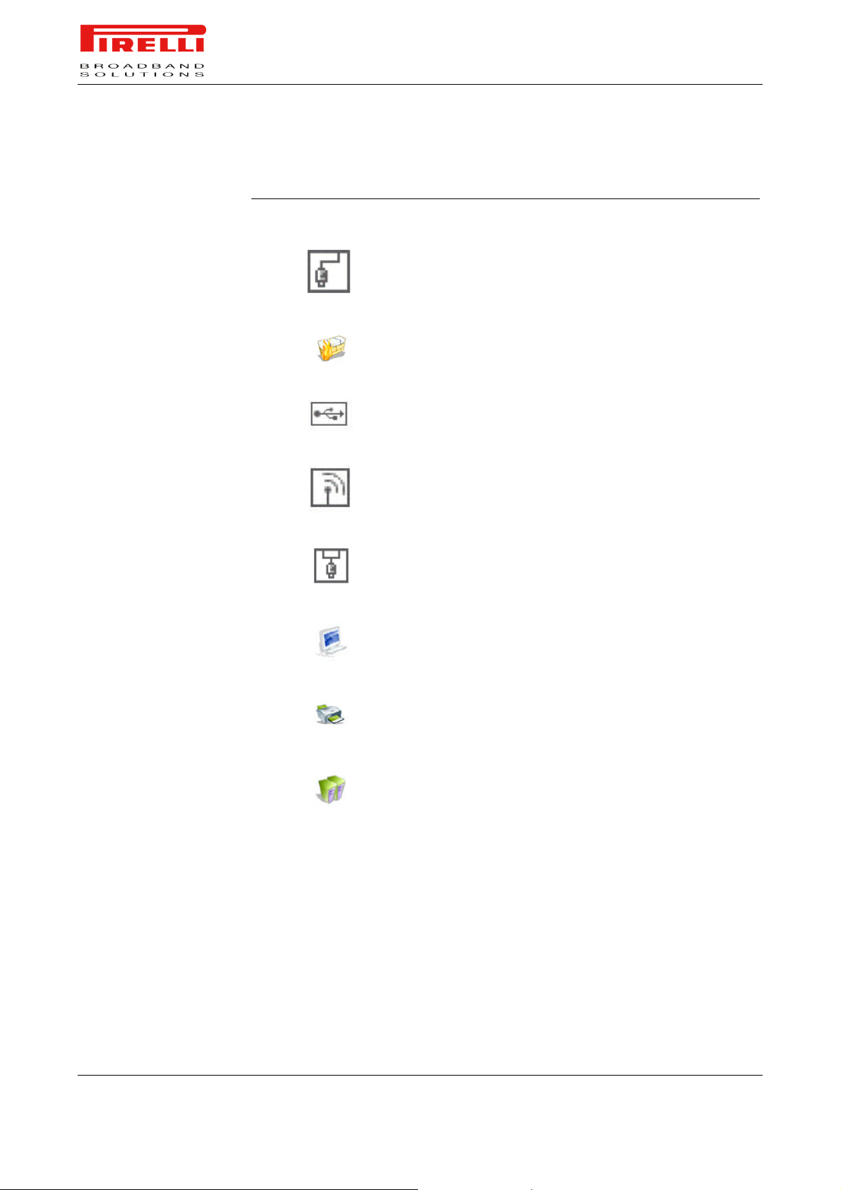
In the following table a list of all available network objects and related description is shown.
TABLE 1. Available Network Objects
Map Symbol Description
It represents the Internet
It represents your DSL Wide Area Network (WAN) connection.
Click this icon to configure the WAN interface
© (2007) Pirelli Broadband Solutions S.p.A. All Rights Reserved. Proprietary Use Pursuant to Cover Page Instructions.
Router Configuration OGU 930500275-A1 29
Page 37
PRG AV4202N
TABLE 1. Available Network Objects
Map Symbol Description
It represents your Ethernet Wide Area Network (WAN) connection
or an Ethernet Local Area Network (LAN) connection. Click this
icon to configure the WAN interface or the Ethernet LAN device
It represents the gateway's Firewall. The height of the wall corresponds to the security level currently selected: Minimum, Typical or
Maximum. Click this icon to configure security settings
It represents a USB LAN connection. Click this icon to
configure network parameters for the USB LAN device
It represents a Wireless LAN connection. Click this icon to configure network parameters for the Wireless LAN device
It represents a bridge connected in the home network. Click this
icon to view the bridge's underlying devices.
It represents a computer (host) connected in the home network.
Each computer connected to the network appears below the network symbol of the network through which it is connected. Click an
icon to view network information for the corresponding computer..
It represents a printer that is connected to the Router and is shared
by network users. Click the icon to view the printer's settings.
It represents a file server that is connected to the Router and is
shared by network users. Click the icon to view the file server configuration.
© (2007) Pirelli Broadband Solutions S.p.A. All Rights Reserved. Proprietary Use Pursuant to Cover Page Instructions.
30 OGU 930500275-A1 Router Configuration
Page 38

Installation
Wizard Section
This chapter will describe the Installation Wizard Section accessible from the
Home Page of the PRG AV4202N upon user authentication to the Router.
Be aware that any configuration changes could compromise your connectivity.
The Installation Wizard enables speedy configuration of your Internet connection.
It is a step-by-step procedure that guides you through your Internet connection
and wireless network setup, and helps you to subscribe for different services.
The wizard progress box, located at the right hand side of the screen, provides
a monitoring tool for the wizard's steps during the installation progress.
After the setup described in this chapter, you can immediately start using your
Router to:
1. Share a broadband connection among multiple users (HTTP, FTP, Telnet,
NetMeeting) and between all of the computers connected to your home network.
2. Build a home network by connecting additional PCs and network devices to
the gateway.
3. Share resources (file servers, printers, etc.) between computers in the home
network using their names; auto-learning DNS enables PRG AV4202N to
automatically detect the network identification names of the LAN PCs, enabling mutual communication using names, not IP addresses.
4. Control network parameters, including DHCP, DNS and WAN settings.
© (2007) Pirelli Broadband Solutions S.p.A. All Rights Reserved. Proprietary Use Pursuant to Cover Page Instructions.
Installation Wizard Section OGU930500275-A1 31
Installation Wizard Section
Page 39
PRG AV4202N
5. View network status, traffic statistics, system log and more.
6. Allow access from the Internet to games and other services provided by
computers in the home network.
7. Prohibit computers in the home network from accessing selected services on
the Internet.
8. Block access to specific Internet Web sites from your home network.
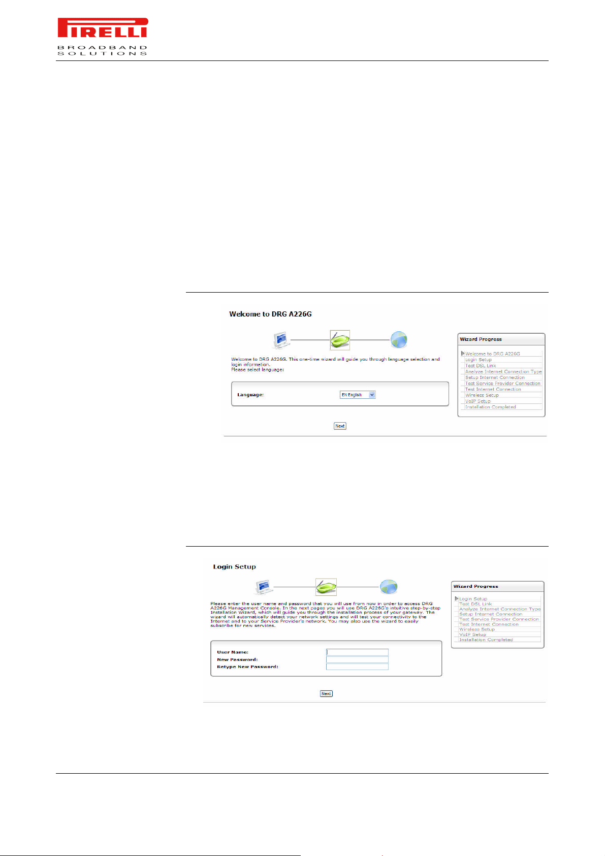
To start the installation wizard, click Next. The wizard procedure will commence,
performing the steps listed in the progress box consecutively, stopping only if a
step fails or if input is required. The following sections describe the wizard steps
along with their success/failure scenarios. If a step fails, use the Retry or Skip
buttons to continue.
FIGURE 1. Installation Wizard Panel
LOG IN SETUP
Insert a user name and password, be sure to remember the log in credentials
used. Its advised to write them down in a peace of paper and store it in a safe
place.
FIGURE 2. Log In Panel
© (2007) Pirelli Broadband Solutions S.p.A. All Rights Reserved. Proprietary Use Pursuant to Cover Page Instructions.
32 OGU 930500275-A1 Installation Wizard Section
Page 40
TEST ETHERNET LINK
ANALYZE INTERNET
CONNECTION TYPE
PRG AV4202N
The first step is a test of the Ethernet connection. This step may fail if the router
cannot detect your Ethernet link (for example, if the cable is unplugged). Verify
that your Ethernet cables are connected properly, and click Retry.
FIGURE 3. Test Ethernet Link Panel
SETUP INTERNET
CONNECTION
TEST SERVICE PROVIDER
CONNECTION
TEST INTERNET
CONNECTION
WIRELESS SETUP
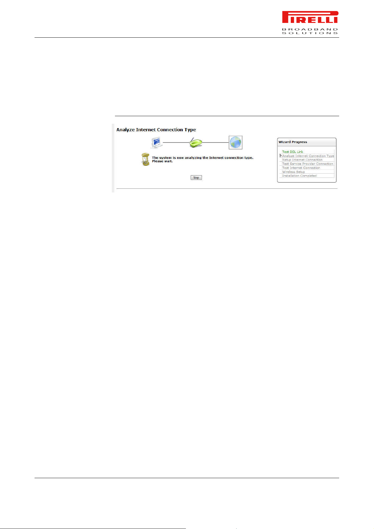
The next step is an analysis of your Internet connection. This step may fail if the
router is unable to detect your Internet connection type.
After three retries, the screen provides a link to manually set the Internet connection type. Click this link. The screen refreshes, displaying a connection type
combo box. To learn about manually configuring your Internet connection,
please refer to the Quick Setup Section of this manual.
If your Internet connection requires login details provided by your Internet Service Provider (ISP) (e.g when using PPPoE).
Enter your user name and password and click Next.
This step tests the connectivity to your ISP.
This step tests the connectivity to the Internet.
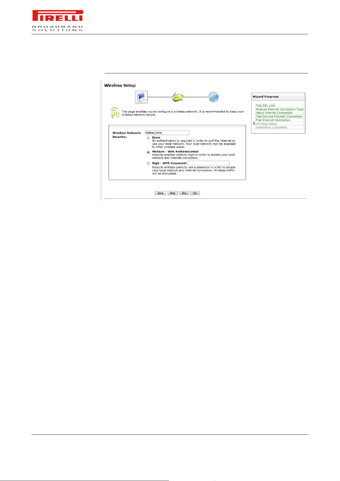
Use this step to configure a wireless network. Enter a name for your wireless
network and select its level of security. Click Next.
© (2007) Pirelli Broadband Solutions S.p.A. All Rights Reserved. Proprietary Use Pursuant to Cover Page Instructions.
Installation Wizard Section OGU 930500275-A1 33
Page 41
PRG AV4202N
FIGURE 4. Wireless Setup Panel
VOIP SETUP
INSTALLATION
COMPLETED
This page enables you to configure a VoIP account.
This screen provides a summary of all the above Internet connection configuration steps and their results. Click Finish to complete the wizard procedure.
© (2007) Pirelli Broadband Solutions S.p.A. All Rights Reserved. Proprietary Use Pursuant to Cover Page Instructions.
34 OGU 930500275-A1 Installation Wizard Section
Page 42

Quick Setup
Section
This chapter will describe the Quick Setup Section accessible from the Home
Page of the PRG AV4202N upon user authentication to the Router.
Be aware that any configuration changes could compromise your connectivity.
When subscribing to a broadband service, you should be aware of the method
by which you are connected to the Internet. Your physical WAN device can be
either Ethernet, DSL, or both. Technical information regarding the properties of
your Internet connection should be provided by your Internet Service Provider
(ISP). For example, your ISP should inform you whether you are connected to
the Internet using a static or dynamic IP address, or what protocols, such as
PPTP or PPPoE, you will be using to communicate over the Internet.
The Router will automatically recognize if you have more than one physical
WAN device on your gateway, and will provide a configuration section for each,
under the 'Internet Connections' section of the 'Quick Setup' screen.
Your WAN connection(s) can be configured using one of the following methods.
Read the configuration instructions relevant to you, by selecting your connection
method from the list below:
1. Point-to-point protocol over Ethernet (PPPoE) over ATM
2. Point-to-point protocol over Ethernet (PPPoE) over PTM
3. Point-to-point protocol over ATM (PPPoA)
4. Routed Ethernet Connection over ATM (ETHoA)
5. Bridged Ethernet Connection over ATM (ETHoA)
© (2007) Pirelli Broadband Solutions S.p.A. All Rights Reserved. Proprietary Use Pursuant to Cover Page Instructions.
Quick Setup Section OGU 930500275-A1 35
Quick Setup Section
Page 43
PRG AV4202N
6. No Internet connection
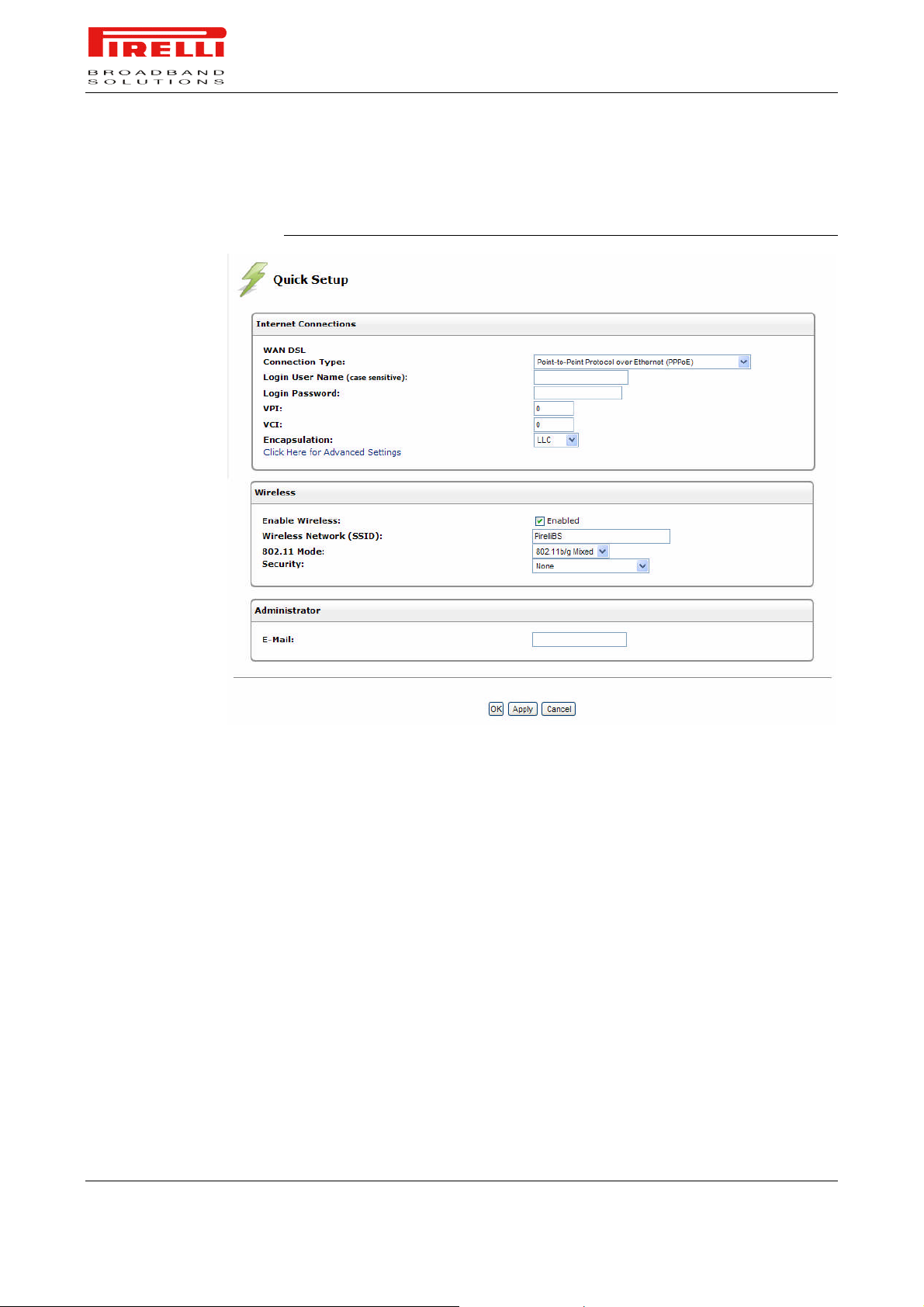
FIGURE 1. Quick Setup Panel
POINT-TO-POINT
PROTOCOL OVER
ETHERNET (PPPOE) OVER
ATM
To configure the Point-to-point protocol over Ethernet, follow these steps:
7. Select 'Point-to-point protocol over Ethernet (PPPoE)' from the 'Connection
Type' combo-box.
8. Your Internet Service Provider (ISP) should provide you with the Login user
name and Login password.
9. If your board features a DSL connection, you will see an 'Automatic PVC
Scan' check box. Select this check box to enable the automatic configuration
of the VPI, VCI and encapsulation parameters (relevant to DSL connections).
ETHERNET (PPPOE) OVER
PTM
To configure the Point-to-point protocol over Ethernet, follow these steps:
© (2007) Pirelli Broadband Solutions S.p.A. All Rights Reserved. Proprietary Use Pursuant to Cover Page Instructions.
36 OGU 930500275-A1 Quick Setup Section
Page 44

POINT-TO-POINT
PROTOCOL OVER ATM
(PPPOA)
PRG AV4202N
1. Select 'Point-to-point protocol over Ethernet (PPPoE)' from the 'Connection
Type' combo-box.
2. Your Internet Service Provider (ISP) should provide you with the Login user
name and Login password.
To configure the Point-to-point protocol over ATM, follow these steps:
1. Select 'Point-to-point protocol over ATM (PPPoA)' from the 'Connection
Type' combo-box
2. Your Internet Service Provider (ISP) should provide you with the following in-
formation:
- Login user name
- Login password
3. By default, the 'Automatic PVC Scan' check box is enabled, which means
that the Router configures the VPI, VCI and encapsulation parameters
automatically. If you would like to configure these parameters manually, uncheck this check box.
- Specify the VPI and VCI values.
- Select the encapsulation method from the combo-box. You can choose
among the following methods: LLC, VCMux and VCMux - HDLC
ROUTED ETHERNET
CONNECTION OVER ATM
(ETHOA)
ROUTED ETHERNET
CONNECTION OVER PTM
(ETHOP)
To configure the Routed Ethernet connection over ATM, follow these steps:
4. Select 'Routed Ethernet Connection over ATM (ETHoA)' from the 'Connec-
tion Type' combo-box
5. Your Internet Service Provider (ISP) should provide you with the following in-
formation:
- Specify the value of the VPI and VCI parameters.
- Select the encapsulation method from the combo-box. You can choose
among the following methods: LLC, VCMux.
- Select the Internet Protocol: Most Internet Service Providers (ISPs) provide
dynamic IP addresses, hence the default "Obtain an IP Address Automatically". Should this not be the case, select the "Use the Following IP Address"
option. The screen will refresh. Enter the IP Address, Subnet Mask, Default
Gateway, and DNS Server details provided to you by your ISP.
To configure the Routed Ethernet connection over PTM, follow these steps:
1. Select 'Routed Ethernet Connection over PTM (ETHoP)' from the 'Connec-
tion Type' combo-box
© (2007) Pirelli Broadband Solutions S.p.A. All Rights Reserved. Proprietary Use Pursuant to Cover Page Instructions.
Quick Setup Section OGU 930500275-A1 37
Page 45

BRIDGED ETHERNET
CONNECTION OVER ATM
(ETHOA)
PRG AV4202N
2. Your Internet Service Provider (ISP) should provide you with the following in-
formation:
- Select the Internet Protocol: Most Internet Service Providers (ISPs) provide
dynamic IP addresses, hence the default "Obtain an IP Address Automatically". Should this not be the case, select the "Use the Following IP Address"
option. The screen will refresh. Enter the IP Address, Subnet Mask, Default
Gateway, and DNS Server details provided to you by your ISP.
To configure the Bridged Ethernet Connection over ATM (ETHoA), follow these
steps:
1. Select 'Bridged Ethernet Connection over ATM (ETHoA)' from the 'Connec-
tion Type' combo-box
2. Your Internet Service Provider (ISP) should provide you with the following in-
formation:
- Specify the value of the VPI and VCI parameters.
- Select the encapsulation method from the combo-box. You can choose
among the following methods: LLC, VCMux
BRIDGED ETHERNET
CONNECTION OVER PTM
(ETHOP)
NO INTERNET
CONNECTION
WIRELESS
ADMINISTRATOR
To configure the Bridged Ethernet Connection over ATM (ETHoA), follow these
steps:
1. Select 'Bridged Ethernet Connection over ATM (ETHoA)' from the 'Connec-
tion Type' combo-box
Select 'No Internet Connection' from the 'Connection Type' combo-box. Choose
this connection type if you do not have an Internet connection, or if you want to
disable all existing connections.
Click the 'Enabled' check box to enable your wireless connection. Specify the
wireless network's ID in the 'SSID' field. The default SSID is 'openrg'.
In this section it is necessary to specify the administrator's e-mail in the 'E-mail'
field. System alerts and notifications are sent to this address.
© (2007) Pirelli Broadband Solutions S.p.A. All Rights Reserved. Proprietary Use Pursuant to Cover Page Instructions.
38 OGU 930500275-A1 Quick Setup Section
Page 46

Network
Connections
Section
This chapter will describe the Network Connections Section accessible from
the Home Page of the PRG AV4202N.
Be aware that any configuration changes could compromise your connectivity.
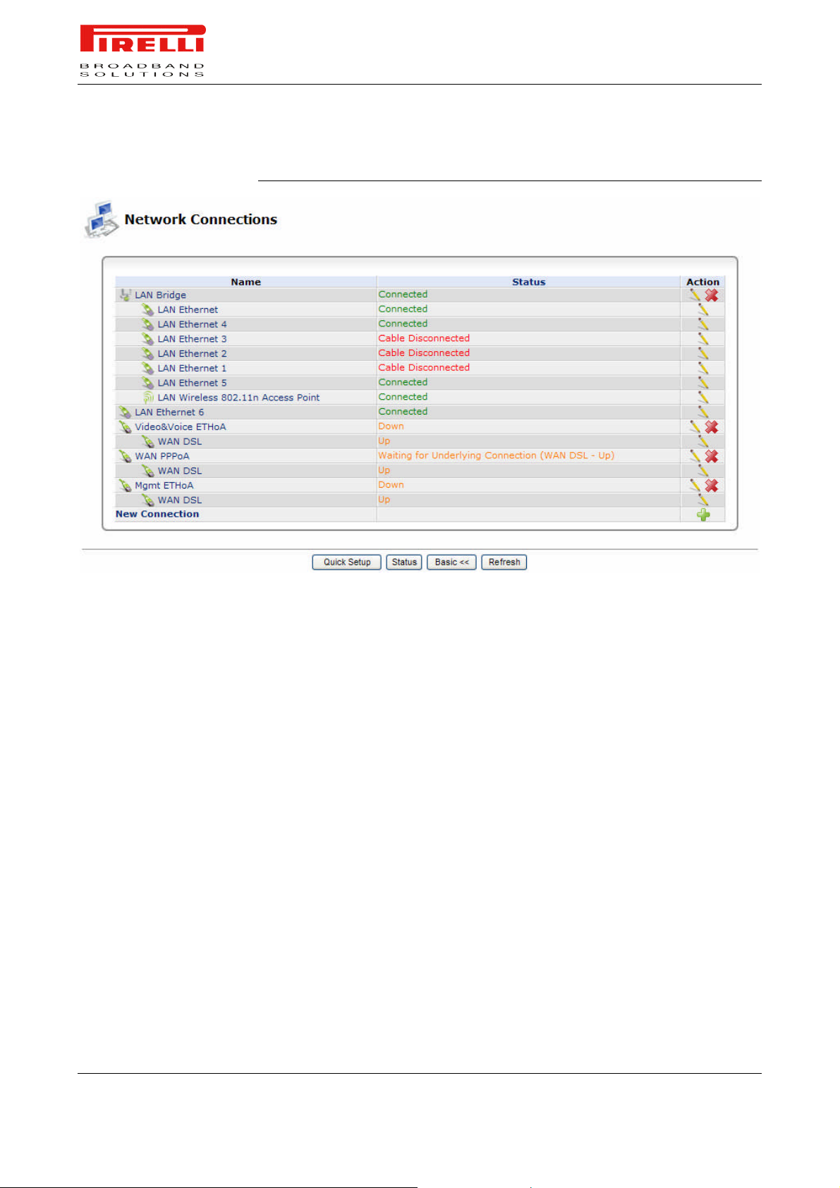
This section (see Figure 1) is intended to present a summary of the Router's
connections, such as WAN and LAN (i.e. Ethernet, USB, Wireless) interfaces.
PRG AV4202N supports various network connections, both physical and logical. The Network Connections screen enables you to configure the various parameters of your physical connections, the LAN and WAN, and create new connections, using tunneling protocols over existing connections, such as PPP and
VPN.
Press the 'Advanced' button to expand the screen and display all connection
entries.
© (2007) Pirelli Broadband Solutions S.p.A. All Rights Reserved. Proprietary Use Pursuant to Cover Page Instructions.
Network Connections Section OGU 930500275-A1 39
Network Connections Section
Page 47
PRG AV4202N
FIGURE 1. Network Connections Panel
LAN BRIDGE
LAN BRIDGE >> GENERAL
The LAN bridge connection is used to combine several LAN devices under one
virtual network. For example, creating one network for LAN Ethernet and LAN
wireless devices.
Please note, that when a bridge is removed, its formerly underlying devices inherit the bridge's DHCP settings. For example, the removal of a bridge that is
configured as DHCP client, automatically configures the LAN devices formerly
constituting the bridge as DHCP clients, with the exact DHCP client configuration.
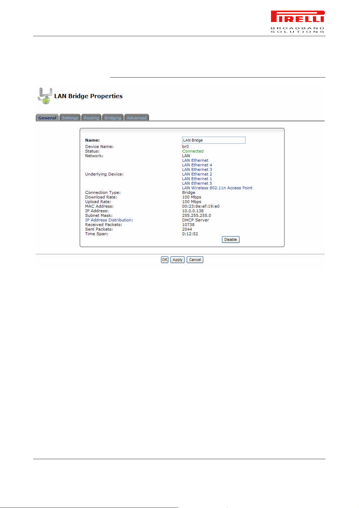
To view and edit the LAN bridge connection settings, click the 'LAN Bridge' link
in the 'Network Connections' screen. The 'LAN Bridge Properties' screen will
appear, displaying a detailed summary of the connection's parameters, under
the 'General' tab. These parameters can be edited in the rest of the screen's
tabs, as described in the following sections.
© (2007) Pirelli Broadband Solutions S.p.A. All Rights Reserved. Proprietary Use Pursuant to Cover Page Instructions.
40 OGU 930500275-A1 Network Connections Section
Page 48
PRG AV4202N
FIGURE 2. LAN Bridge >> General Panel
LAN BRIDGE >> SETTINGS
© (2007) Pirelli Broadband Solutions S.p.A. All Rights Reserved. Proprietary Use Pursuant to Cover Page Instructions.
General. This section displays the connection's general parameters. It is recommended not to change the default values unless familiar with the networking concepts they represent. Since your gateway is configured to operate with
the default values, no parameter modification is necessary.
Network Connections Section OGU 930500275-A1 41
Page 49
PRG AV4202N
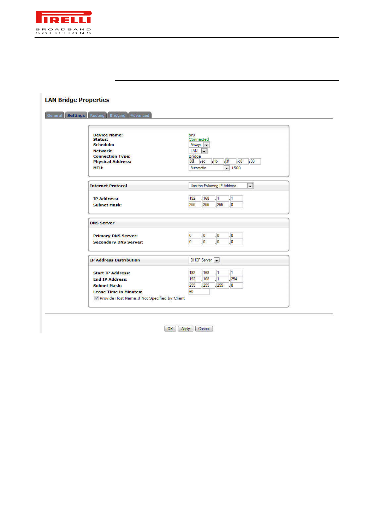
FIGURE 3. LAN Bridge >> Settings Panel
Schedule. By default, the connection will always be active. However, you can
configure scheduler rules in order to define time segments during which the
connection may be active. Once a scheduler rule(s) is defined, this field
changes to a combo-box, allowing you to choose between the available rules.
Network. Select whether the parameters you are configuring relate to a WAN,
LAN or DMZ connection, by selecting the connection type from the combo-box.
Physical Address. The physical address of the network card used for your
network. Some cards allow you to change this address.
MTU. MTU is the Maximum Transmission Unit. It specifies the largest packet
size permitted for Internet transmission. In the default setting, Automatic, the
© (2007) Pirelli Broadband Solutions S.p.A. All Rights Reserved. Proprietary Use Pursuant to Cover Page Instructions.
42 OGU 930500275-A1 Network Connections Section
Page 50

PRG AV4202N
gateway selects the best MTU for your Internet connection. Select "Automatic
by DHCP" to have the DHCP determine the MTU. In case you select "Manual",
it is recommended to enter a value in the 1200 to 1500 range.
Internet Protocol. Select one of the following Internet protocol options from the
'Internet Protocol' combo-box:
- No IP Address: Select 'No IP Address' if you require that your gateway have
no IP address. This can be useful if you are working in an environment where
you are not connected to other networks, such as the Internet.
- Obtain an IP Address Automatically: Your connection is configured by default
to act as a DHCP client. You should keep this configuration in case your service
provider supports DHCP, or if you are connecting using a dynamic IP address.
The server that assigns the gateway with an IP address, also assigns a subnet
mask. You can override the dynamically assigned subnet mask by selecting the
'Override Subnet Mask' and specifying your own mask instead. You can press
the 'Release' button to release the current leased IP address. Once the address
has been released, the button text changes to 'Renew'. Use the 'Renew' button
to renew the leased IP address.
- Use the Following IP Address: Your connection can be configured using a
permanent (static) IP address. Your service provider should provide you with
such an IP address and subnet mask.
DNS Server. Domain Name System (DNS) Server is the method by which Web
site domain names are translated into IP addresses. You can configure the
connection to automatically obtain a DNS server address, or specify such an
address manually, according to the information provided by your ISP. If you
have previously chosen “Obtain an IP Address Automatically”, a combo-box will
appear.
To configure the connection to automatically obtain a DNS server address, select 'Obtain DNS Server Address Automatically' from the 'DNS Server' drop
down menu.
To manually configure DNS server addresses, select 'Use the Following DNS
Server Addresses' from the 'DNS Server' drop down menu. Specify up to two
different DNS server address, one primary, another secondary.
IP Address Distribution. The 'IP Address Distribution' section allows you to
configure the gateway's Dynamic Host Configuration Protocol (DHCP) server
parameters. The DHCP automatically assigns IP addresses to network PCs. If
you enable this feature, make sure that you also configure your network PCs as
DHCP clients. Select one of the following options from the 'IP Address Distribution' combo-box:
DHCP Server.
Start IP Address: The first IP address that may be assigned to a LAN host.
Since the gateway's default IP address is 192.168.1.1, this address must be
192.168.1.2 or greater.
© (2007) Pirelli Broadband Solutions S.p.A. All Rights Reserved. Proprietary Use Pursuant to Cover Page Instructions.
Network Connections Section OGU 930500275-A1 43
Page 51

PRG AV4202N
End IP Address: The last IP address in the range that can be used to automatically assign IP addresses to LAN hosts.
Subnet Mask: A mask used to determine to what subnet an IP address belongs.
An example of a subnet mask value is 255.255.255.0.
Lease Time In Minutes: Each device will be assigned an IP address by the
DHCP server for this amount of time, when it connects to the network. When
the lease expires the server will determine if the computer has disconnected
from the network. If it has, the server may reassign this IP address to a newlyconnected computer. This feature ensures that IP addresses that are not in use
will become available for other computers on the network.
Provide Host Name if Not Specified by Client: If the DHCP client does not have
a host name, the gateway will automatically assign one for him.
DHCP Relay. Your gateway can act as a DHCP relay in case you would like to
dynamically assign IP addresses from a DHCP server other than your gateway's DHCP server. Note that when selecting this option you must also change
Router's WAN to work in routing mode.
1. After selecting 'DHCP Relay' from the drop down menu, a 'New IP Address'
link will appear: Click the 'New IP Address' link. The 'DHCP Relay Server
Address' screen will appear.
2. Specify the IP address of the DHCP server.
3. Click 'OK' to save the settings.
LAN BRIDGE >> ROUTING
Disabled. Select 'Disabled' from the combo-box if you would like to statically
assign IP addresses to your network computers.
You can choose to setup your gateway to use static or dynamic routing. Dynamic routing automatically adjusts how packets travel on the network, whereas
static routing specifies a fixed routing path to neighboring destinations.
© (2007) Pirelli Broadband Solutions S.p.A. All Rights Reserved. Proprietary Use Pursuant to Cover Page Instructions.
44 OGU 930500275-A1 Network Connections Section
Page 52
PRG AV4202N
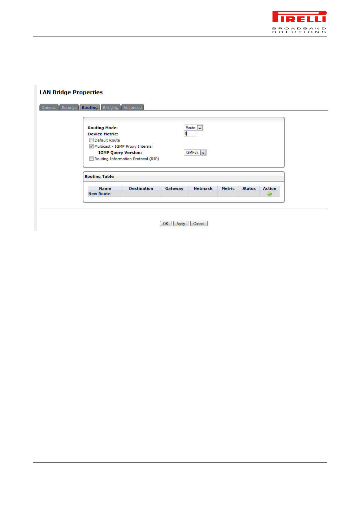
FIGURE 4. LAN Bridge >> Routing Panel
Routing Mode. Select one of the following routing modes:
Route: Use route mode if you want your gateway to function as a router be-
tween two networks.
NAPT: Network Address and Port Translation (NAPT) refers to network ad-
dress translation involving the mapping of port numbers, allowing multiple
machines to share a single IP address. Use NAPT if your LAN encompasses
multiple devices, a topology that necessitates port translation in addition to
address translation.
Device Metric. The device metric is a value used by the gateway to determine
whether one route is superior to another, considering parameters such as
bandwidth, delay, and more.
Default Route. Select this check box to define this device as a the default
route.
Multicast - IGMP Proxy Internal. IGMP proxy enables the system to issue
IGMP host messages on behalf of hosts that the system discovered through
standard IGMP interfaces. IGMP proxy enables the routing of multicast packets
according to the IGMP requests of LAN devices asking to join multicast groups.
Select the 'Multicast IGMP Proxy Internal' check-box to enable this feature.
IGMP Query Version. If “Multicast – IGMP Proxy Internal” is enabled, this list
box allows you to select all three versions of supported IGMP.
© (2007) Pirelli Broadband Solutions S.p.A. All Rights Reserved. Proprietary Use Pursuant to Cover Page Instructions.
Network Connections Section OGU 930500275-A1 45
Page 53
LAN BRIDGE >> BRIDGING
PRG AV4202N
Routing Information Protocol (RIP). Select this check box to enable the Routing Information Protocol (RIP). RIP determines a route based on the smallest
hop count between source and destination. When RIP is enabled, select the following:
Listen to RIP messages - select 'None', 'RIPv1', 'RIPv2' or 'RIPv1/2'.
Send RIP messages - select 'None', 'RIPv1', 'RIPv2-broadcast' or 'RIPv2-
multicast'.
Routing Table. Allows you to add or modify routes when this device is active.
Use the 'New Route' button to add a route or edit existing routes.
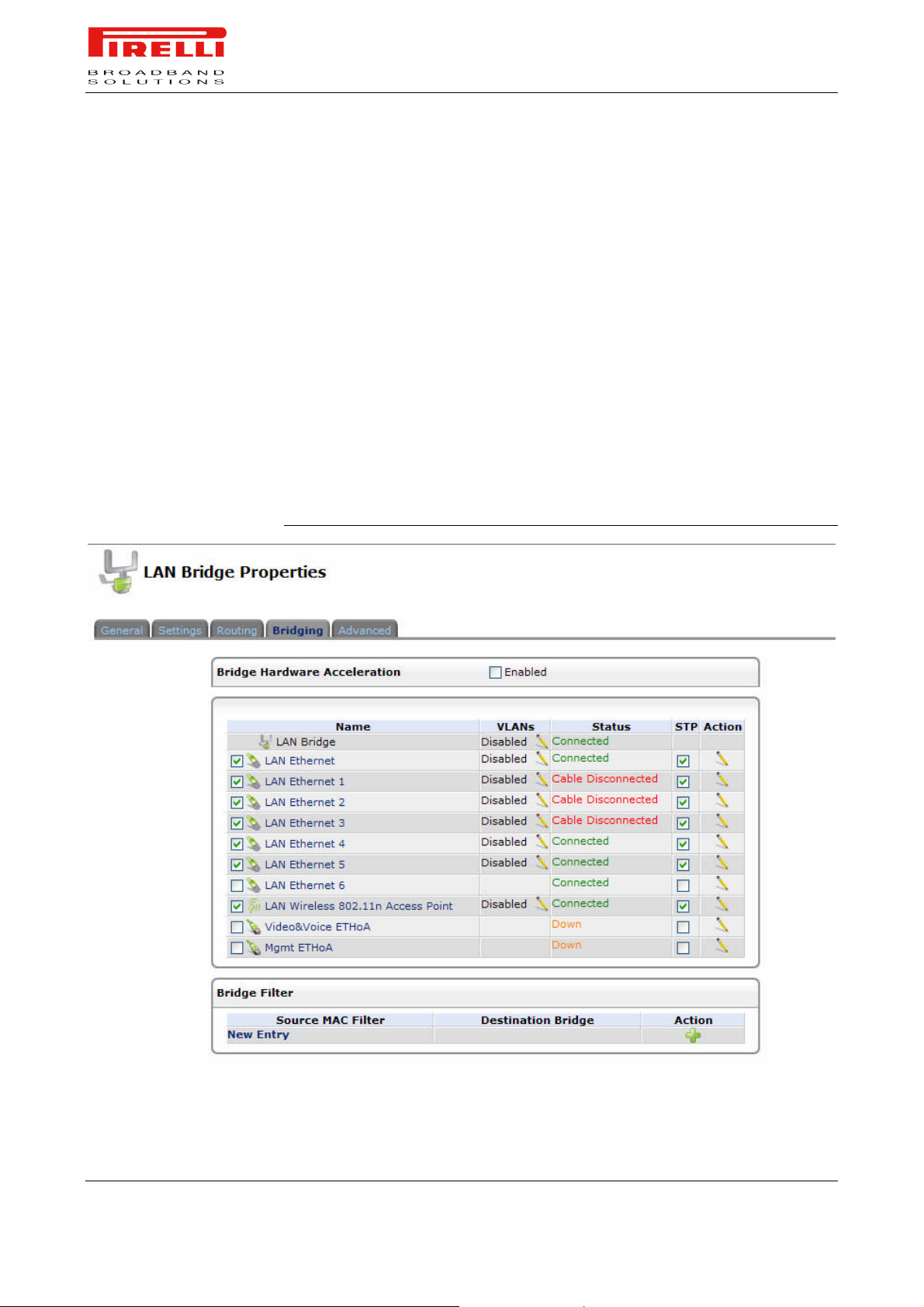
This section allows you to specify the devices that you would like to join under
the network bridge. Click the 'Edit' icon on the VLAN column to assign the network connections to specific virtual LANS.
FIGURE 5. LAN Bridge >> Bridging Panel
© (2007) Pirelli Broadband Solutions S.p.A. All Rights Reserved. Proprietary Use Pursuant to Cover Page Instructions.
46 OGU 930500275-A1 Network Connections Section
Page 54
LAN BRIDGE >>
ADVANCED
PRG AV4202N
Select the 'STP' check box to enable the Spanning Tree Protocol on the device.
You should use this to ensure that there are no loops in your network configuration, and apply these settings in case your network consists of multiple
switches, or other bridges apart from those created by the gateway.
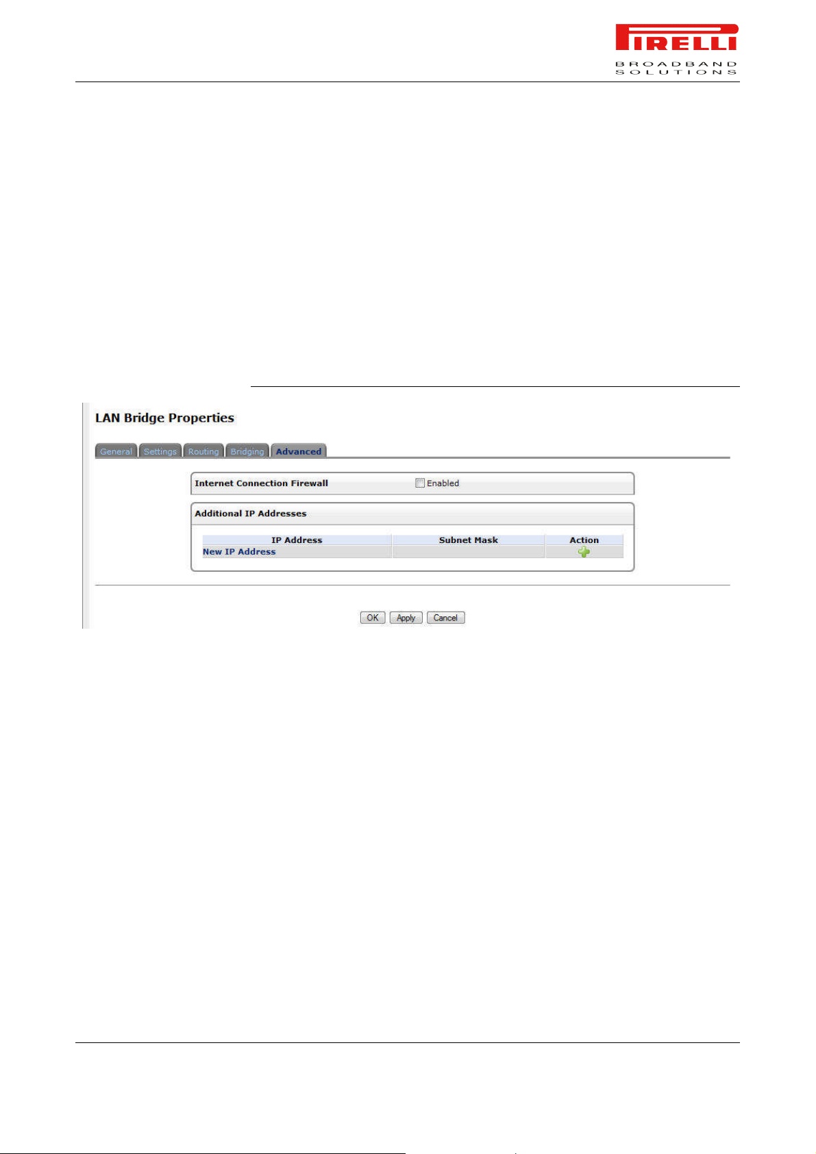
Internet Connection Firewall. Your gateway's firewall helps protect your computer by preventing unauthorized users from gaining access to it through a network such as the Internet. The firewall can be activated per network connection.
To enable the firewall on this network connection, select the 'Enabled' check
box.
FIGURE 6. LAN Bridge >> Advanced Panel
LAN ETHERNET
LAN ETHERNET >>
GENERAL
Additional IP Addresses. You can add alias names (additional IP addresses)
to the gateway by clicking the 'New IP Address' link. This enables you to access
the gateway using these aliases in addition to the 192.168.1.1
A LAN Ethernet connection connects computers to the Router using Ethernet
cables.
To view and edit the LAN Ethernet connection settings, click the 'LAN Ethernet'
link in the 'Network Connections' screen. The 'LAN Ethernet Properties' screen
will appear, displaying a detailed summary of the connection's parameters, under the 'General' tab. These parameters can be edited in the rest of the screen's
tabs, as described in the following sections.
© (2007) Pirelli Broadband Solutions S.p.A. All Rights Reserved. Proprietary Use Pursuant to Cover Page Instructions.
Network Connections Section OGU 930500275-A1 47
Page 55
PRG AV4202N
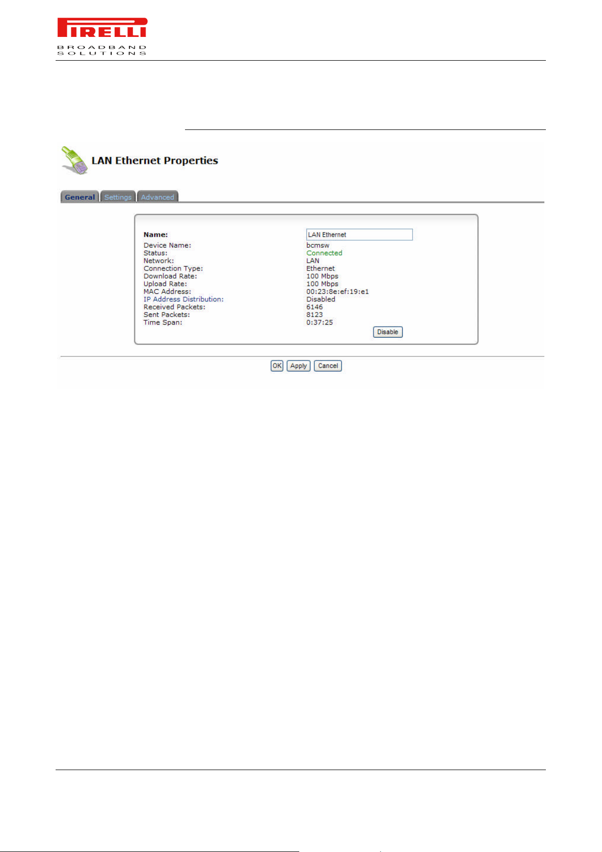
FIGURE 7. LAN Ethernet >> General Panel
LAN ETHERNET >>
SETTINGS
General. This section displays the connection's general parameters. It is re-
commended not to change the default values unless familiar with the networking concepts they represent. Since your gateway is configured to operate with
the default values, no parameter modification is necessary.
© (2007) Pirelli Broadband Solutions S.p.A. All Rights Reserved. Proprietary Use Pursuant to Cover Page Instructions.
48 OGU 930500275-A1 Network Connections Section
Page 56
PRG AV4202N
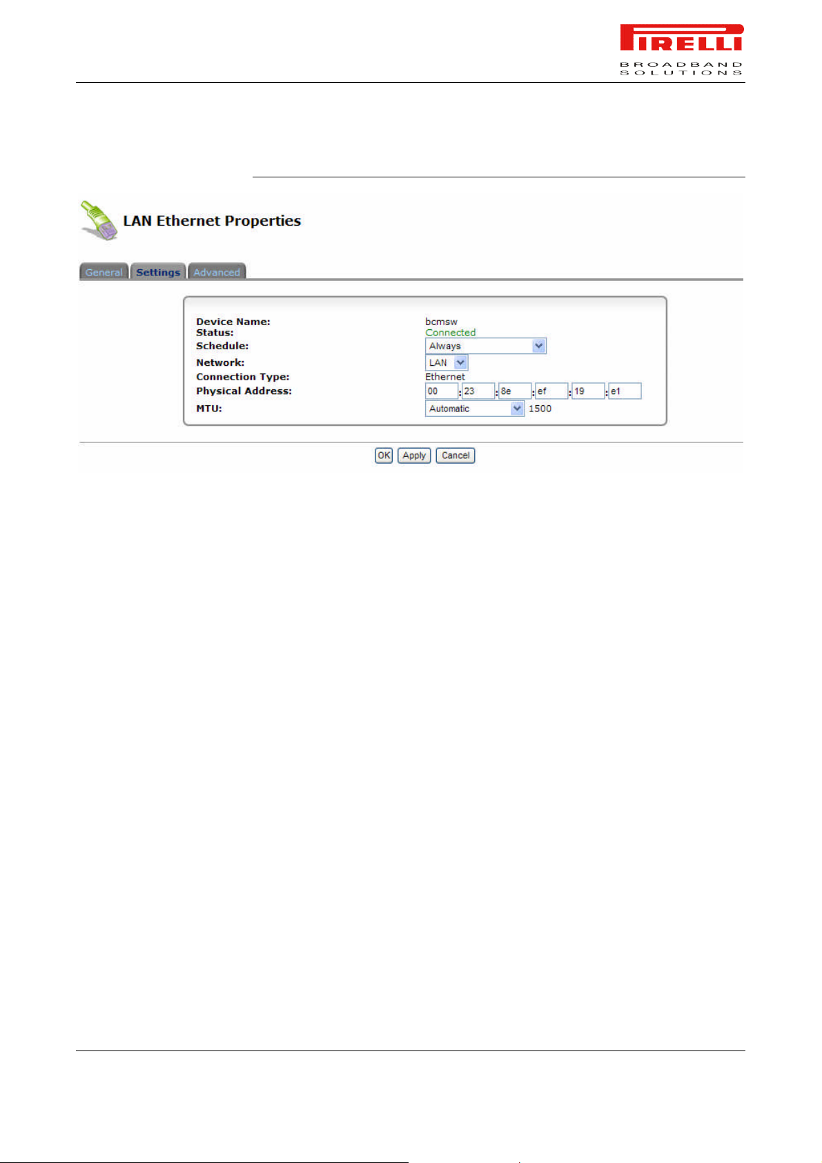
FIGURE 8. LAN Ethernet >> Settings Panel
LAN ETHERNET >>
ADVANCED
Network. Select whether the parameters you are configuring relate to a WAN,
LAN or DMZ connection, by selecting the connection type from the combo-box.
Physical Address. The physical address of the network card used for your
network. Some cards allow you to change this address.
MTU. MTU is the Maximum Transmission Unit. It specifies the largest packet
size permitted for the transmission. In the default setting, Automatic, the gateway selects the best MTU for your Internet connection. Select "Automatic by
DHCP" to have the DHCP determine the MTU. In case you select "Manual", it is
recommended to enter a value in the 1200 to 1500 range.
Internet Connection Firewall. Your gateway's firewall helps protect your computer by preventing unauthorized users from gaining access to it through a network such as the Internet. The firewall can be activated per network connection.
To enable the firewall on this network connection, select the 'Enabled' check
box.
© (2007) Pirelli Broadband Solutions S.p.A. All Rights Reserved. Proprietary Use Pursuant to Cover Page Instructions.
Network Connections Section OGU 930500275-A1 49
Page 57
PRG AV4202N
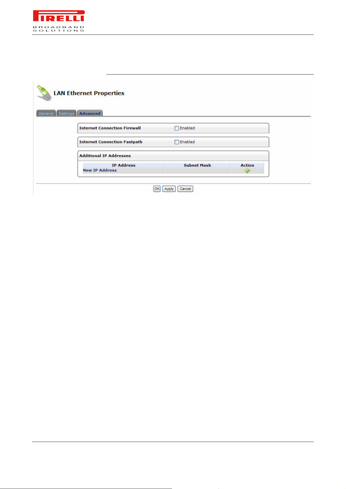
FIGURE 9. LAN Ethernet >> Advanced Panel
Additional IP Addresses. You can add alias names (additional IP addresses)
to the gateway by clicking the 'New IP Address' link. This enables you to access
the gateway using these aliases in addition to the 192.168.1.1
LAN WIRELESS 802.11N
ACCESS POINT
LAN WIRELESS 802.11NN
ACCESS POINT >>
GENERAL
PRG AV4202N integrates multiple layers of wireless security. These include
the IEEE 802.1x port-based authentication protocol, RADIUS client, EAP-MD5,
EAP-TLS, EAP-TTLS, EAP-PEAP, Wi-Fi Protected Access (WPA), WPA2,
WPA and WPA2 (mixed mode) and industry leading Discus Firewall and VPN
applications. In addition, the Router’s built-in authentication server enables
home/SOHO users to define authorized wireless users without the need for an
external RADIUS server.
To view and edit the LAN Wireless connection settings, click the 'LAN Wireless
802.11n Access Point' link in the 'Network Connections' screen. The 'LAN Wireless 802.11n Access Point Properties' screen will appear, displaying a detailed
summary of the connection's parameters, under the 'General' tab. These parameters can be edited in the rest of the screen's tabs, as described in the following sections.
© (2007) Pirelli Broadband Solutions S.p.A. All Rights Reserved. Proprietary Use Pursuant to Cover Page Instructions.
50 OGU 930500275-A1 Network Connections Section
Page 58
PRG AV4202N
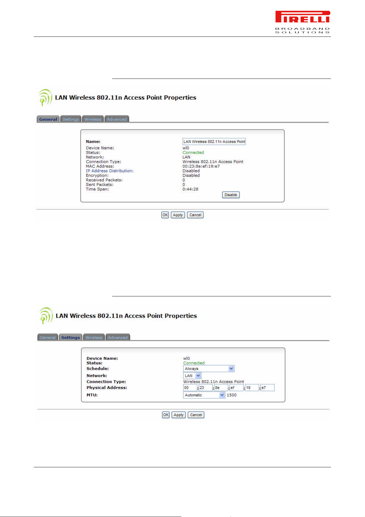
FIGURE 10. LAN Wireless 802.11n Access Point >> General Panel
LAN WIRELESS 802.11N
ACCESS POINT >>
SETTINGS
General. This section displays the connection's general parameters. It is re-
commended not to change the default values unless familiar with the networking concepts they represent. Since your gateway is configured to operate with
the default values, no parameter modification is necessary.
FIGURE 11. LAN Wireless 802.11n Access Point >> Settings Panel
© (2007) Pirelli Broadband Solutions S.p.A. All Rights Reserved. Proprietary Use Pursuant to Cover Page Instructions.
Network Connections Section OGU 930500275-A1 51
Page 59

LAN WIRELESS 802.11N
ACCESS POINT >>
WIRELESS
PRG AV4202N
Schedule. By default, the connection will always be active. However, you can
configure scheduler rules in order to define time segments during which the
connection may be active. Once a scheduler rule(s) is defined, this field
changes to a combo-box, allowing you to choose between the available rules.
Network. Select whether the parameters you are configuring relate to a WAN,
LAN or DMZ connection, by selecting the connection type from the combo-box.
Physical Address. The physical address of the network card used for your
network. Some cards allow you to change this address.
MTU. MTU is the Maximum Transmission Unit. It specifies the largest packet
size permitted for Internet transmission. In the default setting, Automatic, the
gateway selects the best MTU for your Internet connection. Select "Automatic
by DHCP" to have the DHCP determine the MTU. In case you select "Manual",
it is recommended to enter a value in the 1200 to 1500 range.
Wireless Access Point
Use this section to define the basic wireless access point settings.
SSID. The SSID is the network name shared among all points in a wireless
network. The SSID must be identical for all points in the wireless network. It is
case-sensitive and must not exceed 32 characters (use any of the characters
on the keyboard). Make sure this setting is the same for all points in your wireless network. For added security, you should change the default SSID (openrg)
to a unique name.
© (2007) Pirelli Broadband Solutions S.p.A. All Rights Reserved. Proprietary Use Pursuant to Cover Page Instructions.
52 OGU 930500275-A1 Network Connections Section
Page 60
PRG AV4202N
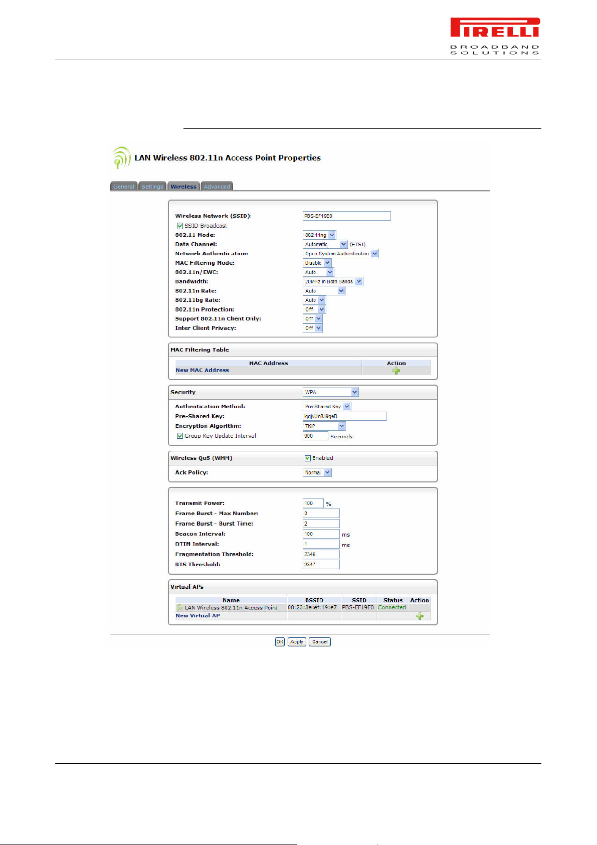
FIGURE 12. LAN Wireless 802.11n Access Point >> Wireless Panel
SSID Broadcast. Select this check-box to enable the SSID's broadcast. SSID
broadcast is used in order to hide the name of the AP (SSID) from clients that
should not be aware to its existence.
© (2007) Pirelli Broadband Solutions S.p.A. All Rights Reserved. Proprietary Use Pursuant to Cover Page Instructions.
Network Connections Section OGU 930500275-A1 53
Page 61

PRG AV4202N
802.11 Mode. Select the Wireless communication standard that is compatible
with you PC's wireless card. You can work in either 802.11n, 802.11g or in
mixed mode.
Country. Select the applying Country from the list box.
Channel. Select the appropriate channel from the list provided to correspond
with your network settings. All devices in your wireless network must broadcast
on different channels in order to function correctly. The channels available depend on the Regulatory Authority (stated in brackets) to which your gateway
conforms.
Network Authentication. The WPA network authentication method is 'Open
System Authentication', meaning that a network key is not used for authentication. When using the 802.1X WEP or Non-802.1X WEP security protocols, this
field changes to a combo-box, offering the 'Shared Key Authentication' method
(which uses a network key for authentication), or both methods combined.
MAC Filtering Mode. You can filter wireless users according to their MAC address, either allowing or denying access. Choose the action to be performed by
selecting it from the drop down menu.
MAC Filtering Table
Use this section to define advanced wireless access point settings.
New MAC Address. Click this link to define filtering of MAC addresses. Enter
the MAC address to be filtered and press the “OK” button. A MAC address list
will appear, upon which the selected filtering action (allow/deny) will be performed.
Security
To configure your wireless security, enable this feature by checking its 'Enabled'
check-box. The screen will refresh, displaying the wireless security options. Use
the 'Stations Security Type' combo-box to select the type of security protocol for
securing your wireless network. You may choose between WPA, WPA2, 802.1x
WEP, and Non-802.1x WEP. The screen will refresh, presenting each protocol's
configuration respectively.
WPA: WPA is a data encryption method for 802.11 wireless LANs.
Authentication Method. Select the authentication method you would like to
use. You can choose between Pre-Shared Key and 802.1x.
Pre-Shared Key. This entry appears only if you had selected this authentication
method. Enter your encryption key in the 'Pre-Shared Key' field. You can use either an ASCII or a Hex value by selecting the value type in the combo-box provided.
© (2007) Pirelli Broadband Solutions S.p.A. All Rights Reserved. Proprietary Use Pursuant to Cover Page Instructions.
54 OGU 930500275-A1 Network Connections Section
Page 62

PRG AV4202N
Encryption Algorithm. Select between Temporal Key Integrity Protocol (TKIP)
and Advanced Encryption Standard (AES) for the encryption algorithm.
Group Key Update Interval. It defines the time interval in seconds for updating
a group key.
WPA2: WPA2 is an enhanced version of WPA, and defines the 802.11i proto-
col.
Authentication Method. Select the authentication method you would like to
use. You can choose between Pre-Shared Key and 802.1x.
Pre-Shared Key. This entry appears only if you had selected this authentication
method. Enter your encryption key in the 'Pre-Shared Key' field. You can use either an ASCII or a Hex value by selecting the value type in the combo-box provided.
Encryption Algorithm. The encryption algorithm used for WPA2 is the Advanced Encryption Standard (AES).
Group Key Update Interval. It defines the time interval in seconds for updating
a group key.
WPA and WPA2 Mixed Mode: WPA and WPA2 is a mixed data encryption
method.
Authentication Method. Select the authentication method you would like to
use. You can choose between Pre-Shared Key and 802.1x.
Pre-Shared Key. This entry appears only if you had selected this authentication
method. Enter your encryption key in the 'Pre-Shared Key' field. You can use either an ASCII or a Hex value by selecting the value type in the combo-box provided.
Encryption Algorithm. The encryption algorithm used for WPA and WPA2 is a
either the Temporal Key Integrity Protocol (TKIP) or the Advanced Encryption
Standard (AES).
Group Key Update Interval. It defines the time interval in seconds for updating
a group key.
802.1x WEP: 802.1x WEP is a data encryption method utilizing a statically or
automatically defined key for wireless clients that use 802.1x for authentication
and WEP for encryption. You may define up to four keys but use only one at a
time.
Generate Keys Automatically. Select this option to generate the encryption
keys automatically rather than entering them manually. The screen will refresh,
hiding the table of keys described below.
© (2007) Pirelli Broadband Solutions S.p.A. All Rights Reserved. Proprietary Use Pursuant to Cover Page Instructions.
Network Connections Section OGU 930500275-A1 55
Page 63

PRG AV4202N
Group Key Update Interval. Defines the time interval in seconds for updating a
group key. Active Select the encryption key to be activated.
Encryption Key. Type the encryption key until the entire field is filled. The key
cannot be shorter than the field's length.
Entry Method. Select the character type for the key: Hex or ASCII. Key Length
Select the key length in bits: 40 or 104 bits.
Key Length. Select the key length in bits: 40 or 104 bits.
Non-802.1x WEP: Non-802.1xWEP is a data encryption method utilizing a
statically-defined key for wireless clients that do not use 802.1x for authentication and WEP for encryption. This method's configuration is virtually identical to
the 802.1x WEP method described above, excluding the automatic key generation and the group key update interval specification. Please refer to the 802.1x
WEP section above when configuring this method. Remember that the static
key must be defined in the wireless Windows client as well.
Wireless QoS (WMM)
Wi-Fi Multimedia (WMM) provides basic Quality of Service (QoS) features to
IEEE 802.11 networks. If your wireless card supports WMM, enable this feature
by checking its 'Enabled' check-box.
Upon enabling WMM, the highest priority is given to Voice packets, decreasing
towards Background packets which receive the lowest priority.
In addition, you can control the reliability of traffic flow. By default, the 'Ack Policy' for each access category is set to "Normal", meaning that an acknowledge
packet is returned for every packet received. This provides a more reliable
transmission but increases traffic load, which decreases performance. You may
choose to cancel the acknowledgement by selecting "No Ack" in the combo-box
of each access category, thus changing the Ack policy. This can be useful for
Voice, for example, where speed of transmission is important and packet loss is
tolerable to a certain degree.
Virtual APs
You can set up multiple wireless LANs on PRG AV4202N , limited only to the
number supported by your wireless card. Each wireless LAN is defined as an
access point.
The 'Virtual APs' section displays the Router's physical wireless access point,
on top of which virtual connections may be created. To create a virtual connection, click the 'New Virtual AP' link.
The new connection will also be added to the network connections list, and will
be configurable like any other connection. You can change the connection's de-
© (2007) Pirelli Broadband Solutions S.p.A. All Rights Reserved. Proprietary Use Pursuant to Cover Page Instructions.
56 OGU 930500275-A1 Network Connections Section
Page 64
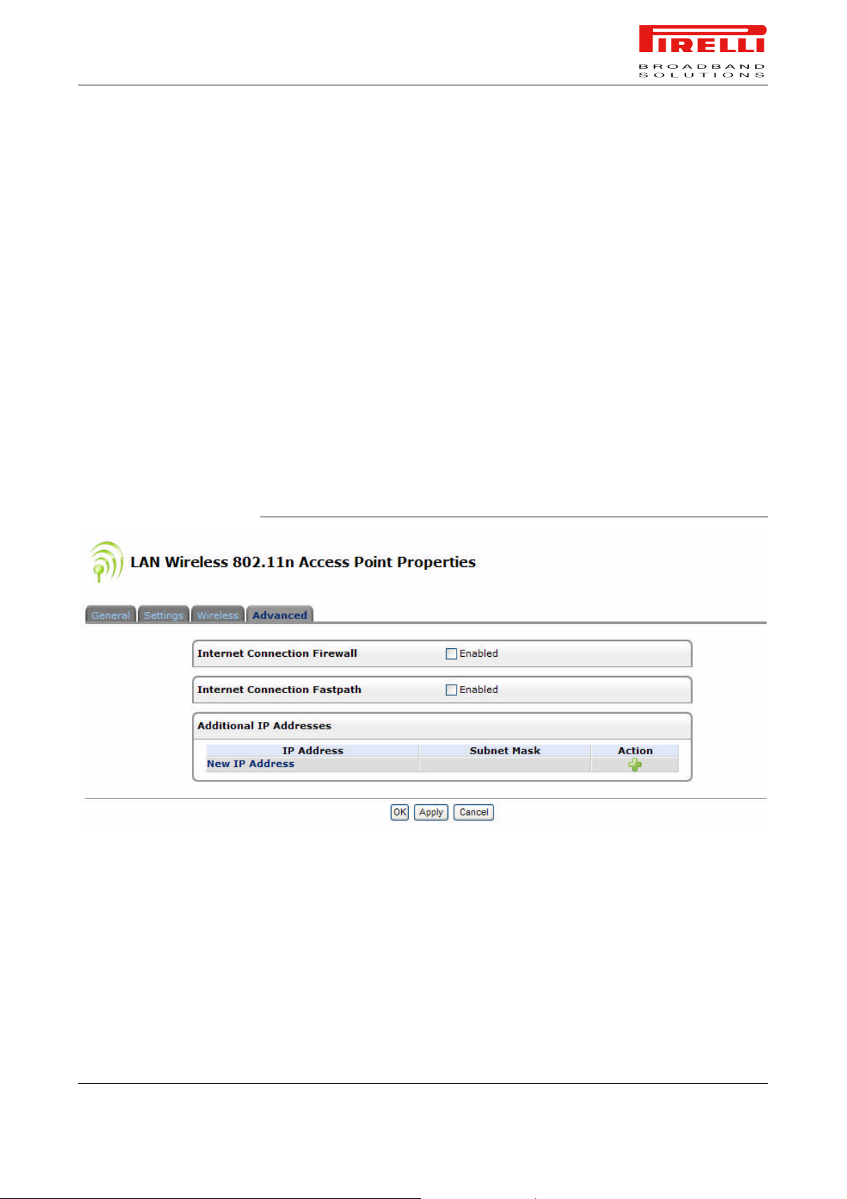
LAN WIRELESS 802.11N
ACCESS POINT >>
ADVANCED
PRG AV4202N
fault name by clicking its Edit action icon and changing the SSID value in the
'Configure LAN Wireless 802.11n Access Point - Virtual AP' screen.
Wireless WDS
It enables wireless bridging of access points within its range. Virtual access
points are used to interact with router's WDS peers, granting LAN users access
to remote wireless networks.
When enabled, a WDS List box is shown.
Internet Connection Firewall. Your gateway's firewall helps protect your computer by preventing unauthorized users from gaining access to it through a network such as the Internet. The firewall can be activated per network connection.
To enable the firewall on this network connection, select the 'Enabled' check
box.
FIGURE 13. LAN Wireless 802.11n Access Point >> Advanced Panel
Additional IP Addresses. You can add alias names (additional IP addresses)
to the gateway by clicking the 'New IP Address' link. This enables you to access
the gateway using these aliases in addition to the 192.168.1.1
WAN DSL
The WAN DSL panels allows you to check and configure the WAN DSL line interface.
© (2007) Pirelli Broadband Solutions S.p.A. All Rights Reserved. Proprietary Use Pursuant to Cover Page Instructions.
Network Connections Section OGU 930500275-A1 57
Page 65
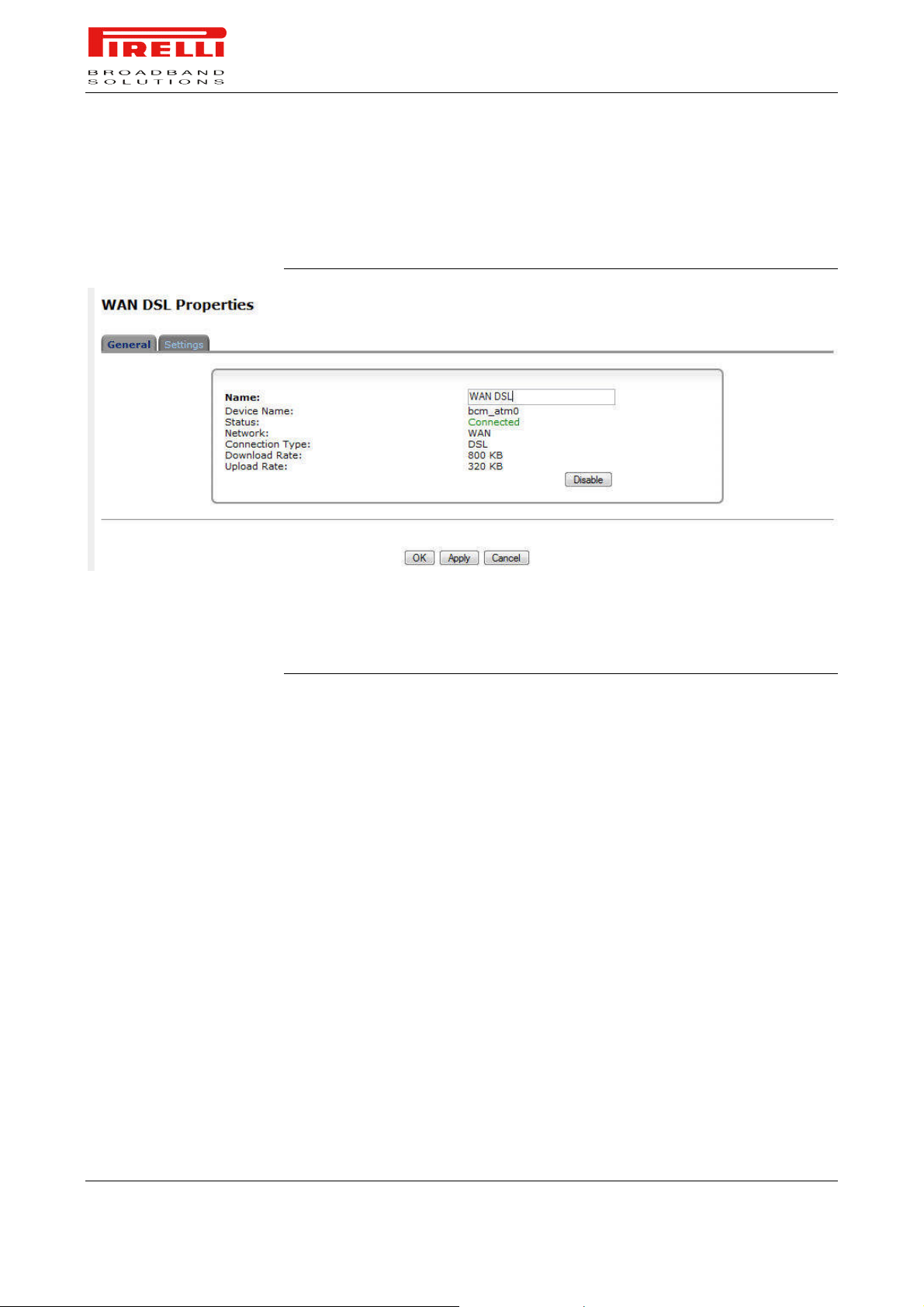
WAN DSL >> GENERAL
PRG AV4202N
From the WAN DSL General panel, it is possible to enable/disable the WAN
DSL interface and to set the WAN DSL friendly name.
FIGURE 14. WAN DSL >> General Panel
WAN DSL >> SETTINGS
From the WAN DSL Settings panel, it is possible to set the Line Mode.
FIGURE 15. WAN DSL >> Settings Panel
© (2007) Pirelli Broadband Solutions S.p.A. All Rights Reserved. Proprietary Use Pursuant to Cover Page Instructions.
58 OGU 930500275-A1 Network Connections Section
Page 66
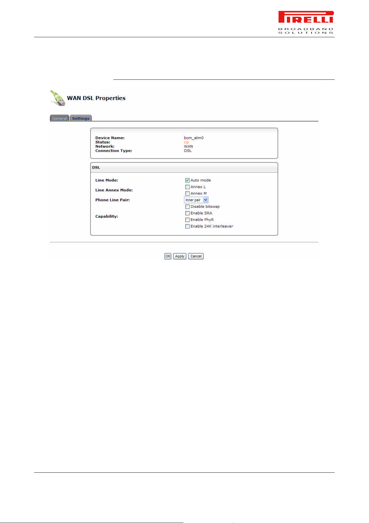
PRG AV4202N
FIGURE 16. WAN DSL >> Settings Panel
© (2007) Pirelli Broadband Solutions S.p.A. All Rights Reserved. Proprietary Use Pursuant to Cover Page Instructions.
Network Connections Section OGU 930500275-A1 59
Page 67

PRG AV4202N
© (2007) Pirelli Broadband Solutions S.p.A. All Rights Reserved. Proprietary Use Pursuant to Cover Page Instructions.
60 OGU 930500275-A1 Network Connections Section
Page 68

Security
Section
This chapter will describe the Security Section accessible from the Home
Page of the PRG AV4202N.
Be aware that any configuration changes could compromise your connectivity.
The Router's gateway security suite includes comprehensive and robust security services: Stateful Packet Inspection Firewall, user authentication protocols
and password protection mechanisms. These features together allow users to
connect their computers to the Internet and simultaneously be protected from
the security threats of the Internet.
The firewall has been exclusively tailored to the needs of the residential/office
user and has been pre-configured to provide optimum security.
The Router's firewall provides both the security and flexibility that home and office users seek. It provides a managed, professional level of network security
while enabling the safe use of interactive applications, such as Internet gaming
and video-conferencing.
Additional features, including surfing restrictions and access control, can also
be easily configured locally by the user through a user-friendly Web-based interface, or remotely by a service provider.
The Router firewall supports advanced filtering, designed to allow comprehensive control over the Firewall’s behavior. You can define specific input and out-
© (2007) Pirelli Broadband Solutions S.p.A. All Rights Reserved. Proprietary Use Pursuant to Cover Page Instructions.
Security Section OGU 930500275-A1 61
Security Section
Page 69

GENERAL
PRG AV4202N
put rules, control the order of logically similar sets of rules and make a distinction between rules that apply to WAN and LAN network devices.
Use the 'General' screen to configure the gateway's basic security settings.
The firewall regulates the flow of data between the home network and the Inter-
net. Both incoming and outgoing data are inspected and then either accepted
(allowed to pass through the Router) or rejected (barred from passing through
the Router) according to a flexible and configurable set of rules. These rules are
designed to prevent unwanted intrusions from the outside, while allowing home
users access to the Internet services that they require.
The firewall rules specify what types of services available on the Internet may
be accessed from the home network and what types of services available in the
home network may be accessed from the Internet. Each request for a service
that the firewall receives, whether originating in the Internet or from a computer
in the home network, is checked against the set of firewall rules to determine
whether the request should be allowed to pass through the firewall. If the request is permitted to pass, then all subsequent data associated with this request
(a “session”) will also be allowed to pass, regardless of its direction.
For example, when you point your Web browser to a Web page on the Internet,
a request is sent out to the Internet for this page. When the request reaches the
Router the firewall will identify the request type and origin - HTTP and a specific
PC in your home network, in this case. Unless you have configured access control to block requests of this type from this computer, the firewall will allow this
request to pass out onto the Internet. When the Web page is returned from the
Web server the firewall will associate it with this session and allow it to pass,
regardless of whether HTTP access from the Internet to the home network is
blocked or permitted.
The important thing to note here is that it is the origin of the request, not subsequent responses to this request, that determines whether a session can be established or not. You may choose from among three pre-defined security levels
for the Router: Minimum, Typical, and Maximum (the default setting). The table
below summarizes the behavior of the Router for each of the three security levels.
© (2007) Pirelli Broadband Solutions S.p.A. All Rights Reserved. Proprietary Use Pursuant to Cover Page Instructions.
62 OGU 930500275-A1 Security Section
Page 70
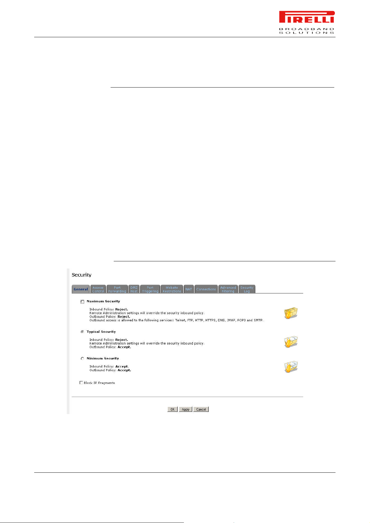
PRG AV4202N
TABLE 1. Security Levels
Requests Originating
in the WAN (Incoming
Security Level
Maximum Security
(Default)
Traffic)
Blocked: no access to
home network from Internet, except as configured
in the Port Forwarding,
DMZ host and Remote
Access screens
Requests Originating in the LAN
(Outgoing Traffic)
Limited: by default, only commonly-used
services, such as Web browsing and email, are permitted
Typical Security Blocked: no access to
home network from Internet, except as configured
in the Port Forwarding,
DMZ host and Remote
Access screens
Minimum Security Unrestricted: permits full
access from Internet to
home network; all connection attempts permitted.
FIGURE 1. Security General panel
Unrestricted: all services are permitted,
except as configured in the Access Control screen
Unrestricted: all services are permitted,
except as configured in the Access Control screen
© (2007) Pirelli Broadband Solutions S.p.A. All Rights Reserved. Proprietary Use Pursuant to Cover Page Instructions.
Security Section OGU 930500275-A1 63
Page 71
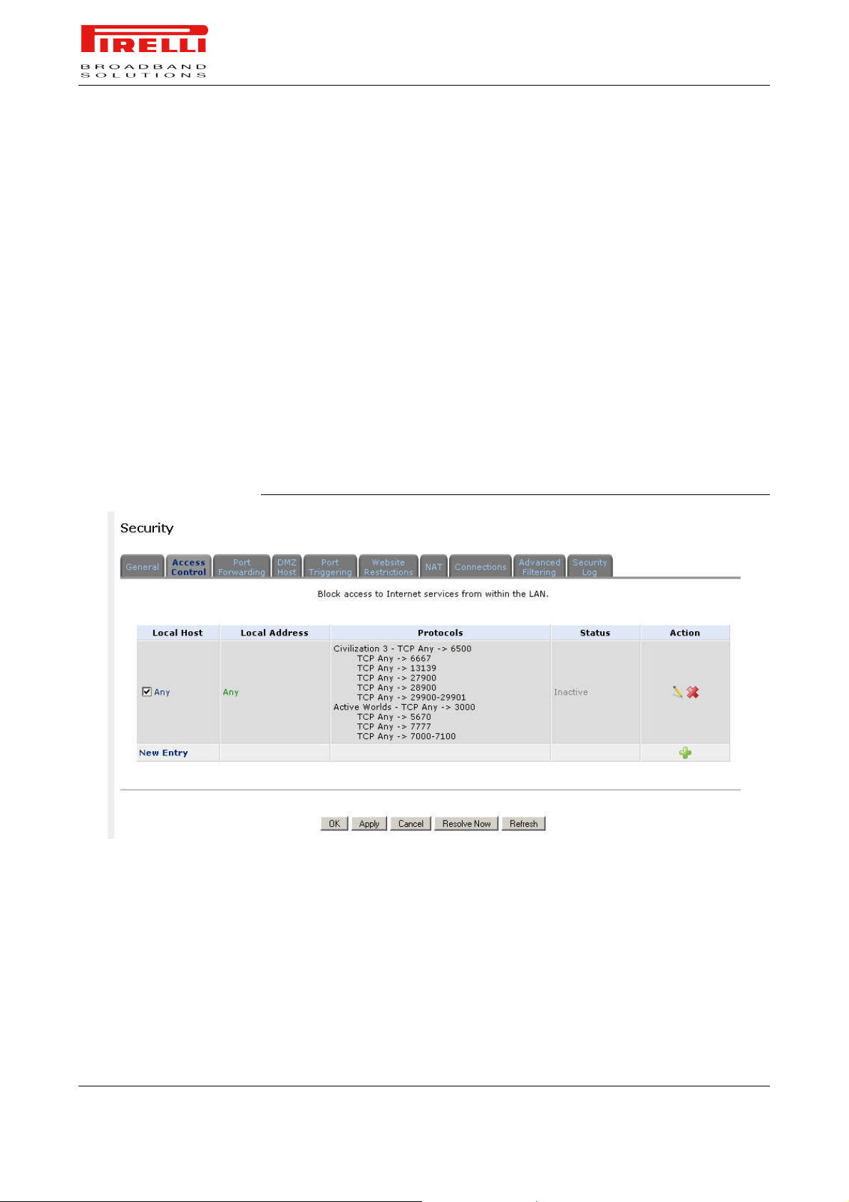
ACCESS CONTROL
PRG AV4202N
You may want to block specific computers within the home network (or even the
whole network) from accessing certain services on the Internet. For example,
you may want to prohibit one computer from surfing the Web, another computer
from transferring files using FTP, and the whole network from receiving incoming e-mail.
Access Control defines restrictions on the types of requests that may pass from
the home network out to the Internet, and thus may block traffic flowing in both
directions. It can also be used for allowing specific services when maximum security is configured. In the e-mail example given above, you may prevent computers in the home network from receiving e-mail by blocking their outgoing requests to POP3 servers on the Internet.
There are numerous services you should consider blocking, such as popular
game and file sharing servers. For example, if you want to make sure that your
employees do not put your business at risk from illegally traded copyright files,
you may want to block several popular P2P and file sharing applications.
FIGURE 2. Access Control panel
To allow or restrict services:
1. Select the 'Access Control' tab in the 'Security' management screen. The
'Access Control' screen will appear.
2. Click the 'New Entry' link. The 'Add Access Control Rule' screen will appear
3. The Address combo-box provides you the ability to specify the computer or
group of computers for which you would like to apply the access control rule.
You can select between any, a specific computer in your LAN, or 'User De-
© (2007) Pirelli Broadband Solutions S.p.A. All Rights Reserved. Proprietary Use Pursuant to Cover Page Instructions.
64 OGU 930500275-A1 Security Section
Page 72

PORT FORWARDING
PRG AV4202N
fined'. If you choose the 'User Defined' option, the 'Edit Network Object'
screen will appear. Specifying an address is done by creating a 'Network
Object';
4. The Protocol combo-box lets you select or specify the type of protocol that
will be used. Selecting the 'Show All Services' option will expand the list of
available protocols. Select a protocol or add a new one using the 'User Defined' option. This will commence a sequence that will add a new service,
representing the protocol.
5. Select the 'Reply an HTML page to the blocked client' check-box to display
the following message to the client: “Access Denied - this computer is not allowed to surf the WAN. Please contact your admin.”. When this check-box is
unselected, the client's packets will simply be ignored and he/she will not receive any notification.
6. The Schedule combo-box allows you to define the time period during which
this rule will take effect. By default, the rule will always be active. However,
you can configure scheduled rules by selecting 'User Defined'.
7. Click the 'OK' button to save your changes. The 'Access Control' screen will
display a summary of the rule that you just added.
In its default state, PRG AV4202N blocks all external users from connecting to
or communicating with your network.
Therefore the system is safe from hackers who may try to intrude on the network and damage it. However, you may want to expose your network to the
Internet in certain limited and controlled ways in order to enable some applications to work from the LAN (game, voice and chat applications, for example)
and to enable Internet-access to servers in the home network. The Port Forwarding feature supports both of these functionalities. If you are familiar with
networking terminology and concepts, you may have encountered this topic referred to as “Local Servers”.
The 'Port Forwarding' screen lets you define the applications that require special handling by the Router.
All you have to do is select the application's protocol and the local IP address of
the computer that will be using or providing the service. If required, you may
add new protocols in addition to the most common ones provided by the Router.
For example, if you wanted to use a File Transfer Protocol (FTP) application on
one of your PCs, you would simply select 'FTP' from the list and enter the local
IP address or host name of the designated computer.
All FTP-related data arriving at the Router from the Internet will henceforth be
forwarded to the specified computer. Similarly, you can grant Internet users access to servers inside your home network, by identifying each service and the
PC that will provide it. This is useful, for example, if you want to host a Web
server inside your home network. When an Internet user points his/her browser
© (2007) Pirelli Broadband Solutions S.p.A. All Rights Reserved. Proprietary Use Pursuant to Cover Page Instructions.
Security Section OGU 930500275-A1 65
Page 73

PRG AV4202N
to the Router's external IP address, the gateway will forward the incoming HTTP
request to your Web server.
With one external IP address (Router's main IP address), different applications
can be assigned to your LAN computers, however each type of application is
limited to use one computer. For example, you can define that FTP will use address X to reach computer A and Telnet will also use address X to reach computer A, but attempting to define FTP to use address X to reach both computer
A and B will fail. The Router therefore provides the ability to add additional public IP addresses to port forwarding rules, which you must first obtain from your
ISP, and enter into the 'NAT IP Addresses Pool'. You will then be able to define
FTP to use address X to reach computer A and address Y to reach computer B.
Additionally, port forwarding enables you to redirect traffic to a different port instead of the one to which it was designated.
Lets say, that you have a Web server running on your PC on port 8080 and you
want to grant access to this server to anyone who accesses the Router via
HTTP. To accomplish this, do the following:
Define a port forwarding rule for the HTTP service, with the PC's IP or host
name.
Specify 8080 in the 'Forward to Port' field.
All incoming HTTP traffic will now be forwarded to the PC running the Web
server on port 8080.
When setting a port forwarding service, you must ensure that the port is not al-
ready in use by another application, which may stop functioning. A common example is when using SIP signaling in Voice over IP - the port used by the gateway's VoIP application (5060) is the same port on which port forwarding is set
for LAN SIP agents.
© (2007) Pirelli Broadband Solutions S.p.A. All Rights Reserved. Proprietary Use Pursuant to Cover Page Instructions.
66 OGU 930500275-A1 Security Section
Page 74
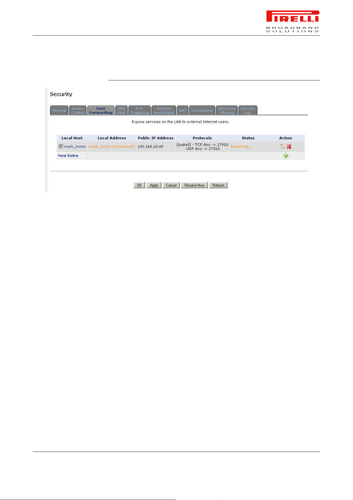
PRG AV4202N
FIGURE 3. Port Forwarding panel
To add a new port forwarding service:
1. Select the 'Port Forwarding' tab in the 'Security' management screen. The
'Port Forwarding' screen will appear
2. Click the 'New Entry' link. The 'Add Port Forwarding Rule' screen will appear
3. Select the 'Specify Public IP Address' check-box if you would like to apply
this rule on a specific external IP address. The screen will refresh
4. Enter the additional external IP address in the 'Public IP Address' field.
5. Enter the host name or IP address of the computer that will provide the ser-
vice (the “server”) in the 'Local Host' field. Note that unless an additional external IP address has been added, only one LAN computer can be assigned
to provide a specific service or application.
6. The Protocol combo-box lets you select or specify the type of protocol that
will be used. Selecting the 'Show All Services' option will expand the list of
available protocols. Select a protocol or add a new one using the 'User Defined' option. This will commence a sequence that will add a new service,
representing the protocol.
7. By default, the Router will forward traffic to the same port as the incoming
port. If you wish to redirect traffic to a different port, select the 'Specify' option. The screen will refresh, and an additional field will appear enabling you
to enter the port number.
8. The Schedule combo-box allows you to define the time period during which
this rule will take effect. By default, the rule will always be active. However,
you can configure scheduled rules by selecting 'User Defined'.
9. Click the 'OK' button to save your changes. The 'Port Forwarding' screen will
display a summary of the rule that you just added.
© (2007) Pirelli Broadband Solutions S.p.A. All Rights Reserved. Proprietary Use Pursuant to Cover Page Instructions.
Security Section OGU 930500275-A1 67
Page 75
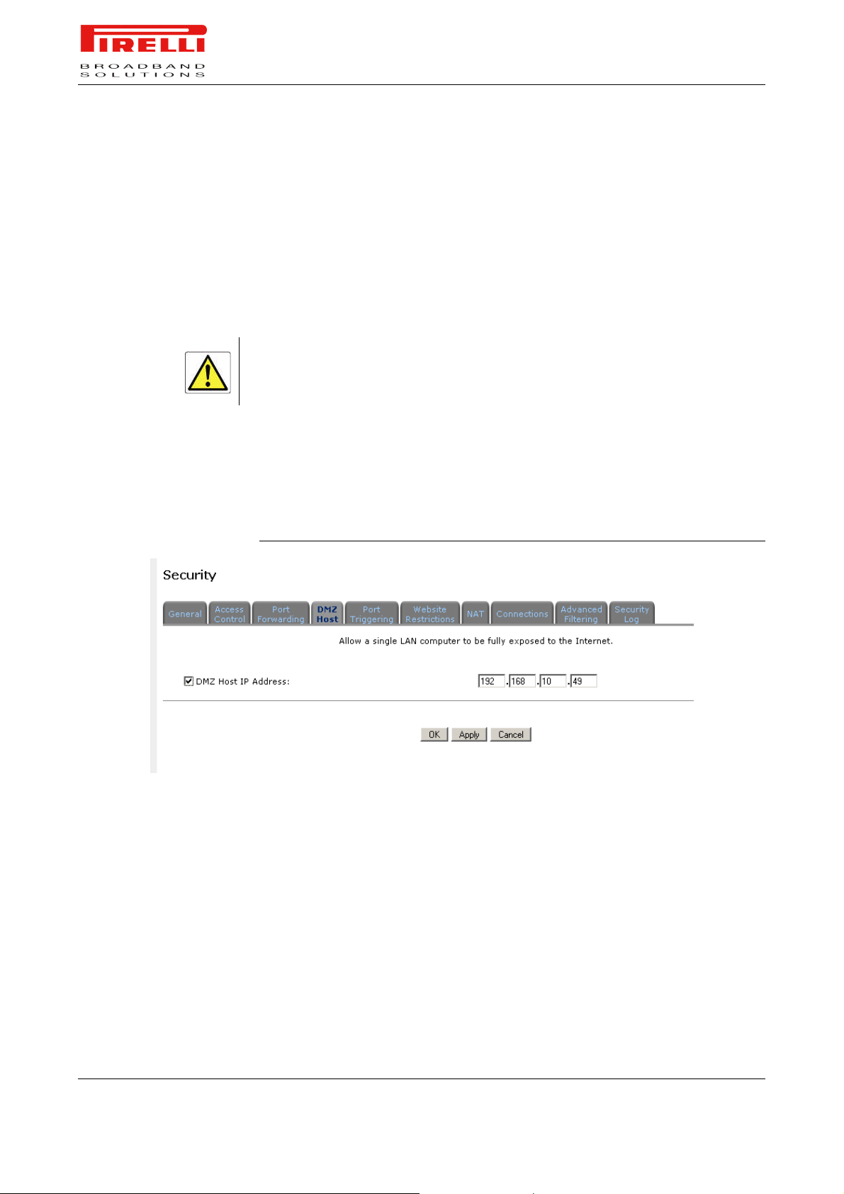
DMZ HOST
PRG AV4202N
The DMZ (Demilitarized) Host feature allows one local computer to be exposed
to the Internet.
Designate a DMZ host when:
You wish to use a special-purpose Internet service, such as an on-line game
or video-conferencing program, that is not present in the Port Forwarding list
and for which no port range information is available.
You are not concerned with security and wish to expose one computer to all
services without restriction.
A DMZ host is not protected by the firewall and may be vulnerable to attack. Designating a DMZ host
may also put other computers in the home network at risk. When designating a DMZ host, you must
consider the security implications and protect it if necessary.
An incoming request for access to a service in the home network, such as a
Web-server, is handled by the Router. PRG AV4202N will forward this request
to the DMZ host (if one is designated) unless the service is being provided by
another PC in the home network (assigned in Port Forwarding), in which case
that PC will receive the request instead.
FIGURE 4. DMZ Host panel
To designate a local computer as a DMZ Host:
1. Select the 'DMZ Host' tab in the 'Security' management screen. The 'DMZ
Host' screen will appear
2. Enter the local IP address of the computer that you would like to designate
as a DMZ host, and select the check-box. Note that only one LAN computer
may be a DMZ host at any time.
3. Click 'OK' to save the settings.
© (2007) Pirelli Broadband Solutions S.p.A. All Rights Reserved. Proprietary Use Pursuant to Cover Page Instructions.
68 OGU 930500275-A1 Security Section
Page 76
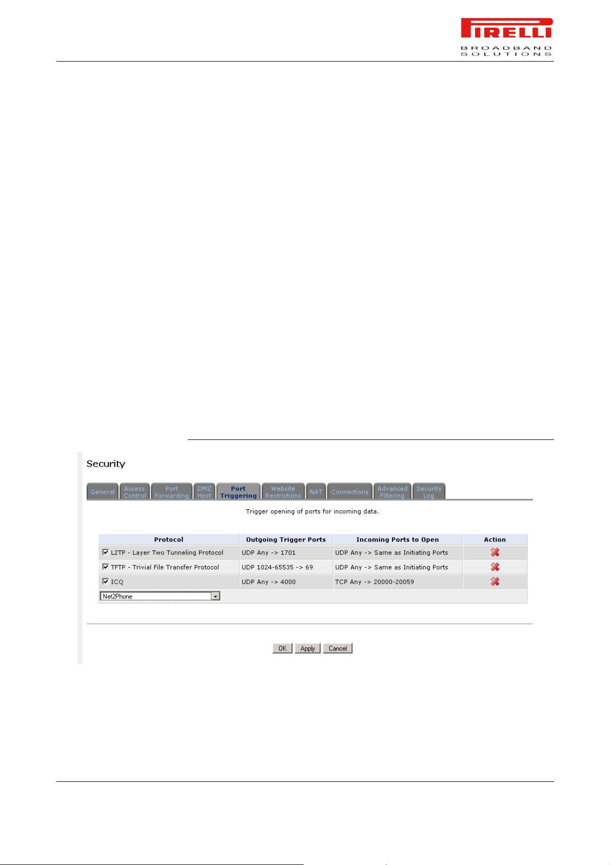
PORT TRIGGERING
PRG AV4202N
Port triggering can be used for dynamic port forwarding configuration. By setting
port triggering rules, you can allow inbound traffic to arrive at a specific LAN
host, using ports different than those used for the outbound traffic. This is called
port triggering since the outbound traffic triggers to which ports inbound traffic is
directed.
For example, consider a gaming server that is accessed using UDP protocol on
port 2222. The gaming server responds by connecting the user using UDP on
port 3333 when starting gaming sessions. In such a case you must use port
triggering, since this scenario conflicts with the following default firewall settings:
The firewall blocks inbound traffic by default.
The server replies to the Router's IP, and the connection is not sent back to
your host, since it is not part of a session.
In order to solve this you need to define a Port Triggering entry, which allows
inbound traffic on UDP port 3333, only after a LAN host generated traffic to
UDP port 2222. This will result in accepting the inbound traffic from the gaming
server, and sending it back to the LAN Host which originated the outgoing traffic
to UDP port 2222.
WEB SITE RESTRICTIONS
Select the 'Port Triggering' tab in the 'Security' management screen. The 'Port
Triggering' screen will appear.
FIGURE 5. Port Triggering panel
You may configure the Router to block specific Internet web sites so that they
cannot be accessed from computers in the home network. Moreover, restric-
© (2007) Pirelli Broadband Solutions S.p.A. All Rights Reserved. Proprietary Use Pursuant to Cover Page Instructions.
Security Section OGU 930500275-A1 69
Page 77
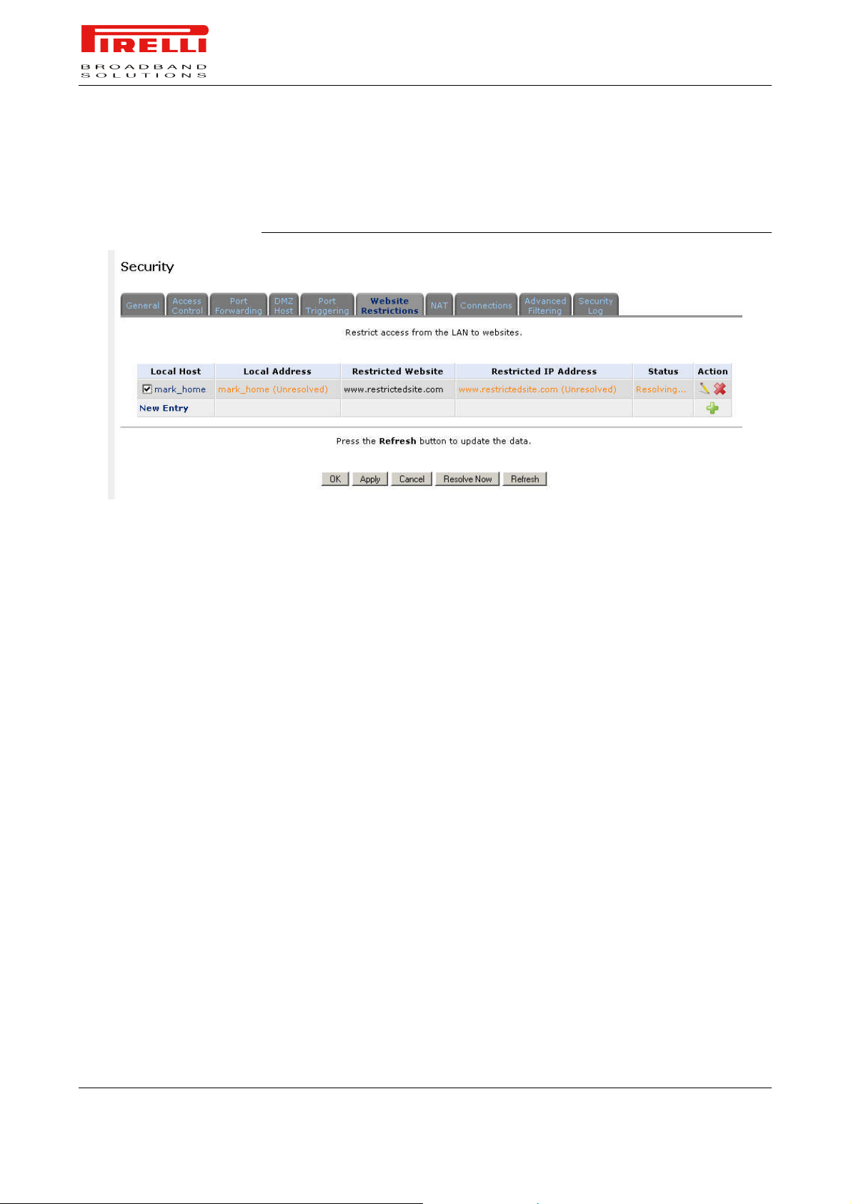
PRG AV4202N
tions can be applied to a comprehensive and automatically updated table of
sites to which access is not recommended.
FIGURE 6. Web Site Restrictions panel
NAT
To block access to a web site:
1. Click the 'Web Site Restrictions' tab in the 'Security' management screen
2. Click the 'New Entry' link. The 'Restricted Web Site' screen will appear
3. Enter the web site address (IP address or URL) that you would like to make
inaccessible from your home network (all Web pages within the site will also
be blocked). If the web site address has multiple IP addresses, the Router
will resolve all additional addresses and automatically add them to the restrictions table.
4. The Local Host combo-box provides you the ability to specify the computer
or group of computers for which you would like to apply the web site restriction. You can select between any, a specific computer in your LAN, or 'User
Defined'. If you choose the 'User Defined' option, the 'Edit Network Object'
screen will appear. Specifying an address is done by creating a 'Network
Object'.
5. The Schedule combo-box allows you to define the time period during which
this rule will take effect. By default, the rule will always be active. However,
you can configure scheduled rules by selecting 'User Defined'.
6. Click 'OK' to save the settings.You will be returned to the previous screen
while the Router attempts to find the site. 'Resolving ...' will appear in the
Status column while the site is being located (the URL is 'resolved' into one
or more IP addresses).
PRG AV4202N features a configurable Network Address Translation (NAT)
and Network Address Port Translation (NAPT) mechanism, allowing you to control the network addresses and ports of packets routed through your gateway.
When enabling multiple computers on your network to access the Internet using
© (2007) Pirelli Broadband Solutions S.p.A. All Rights Reserved. Proprietary Use Pursuant to Cover Page Instructions.
70 OGU 930500275-A1 Security Section
Page 78
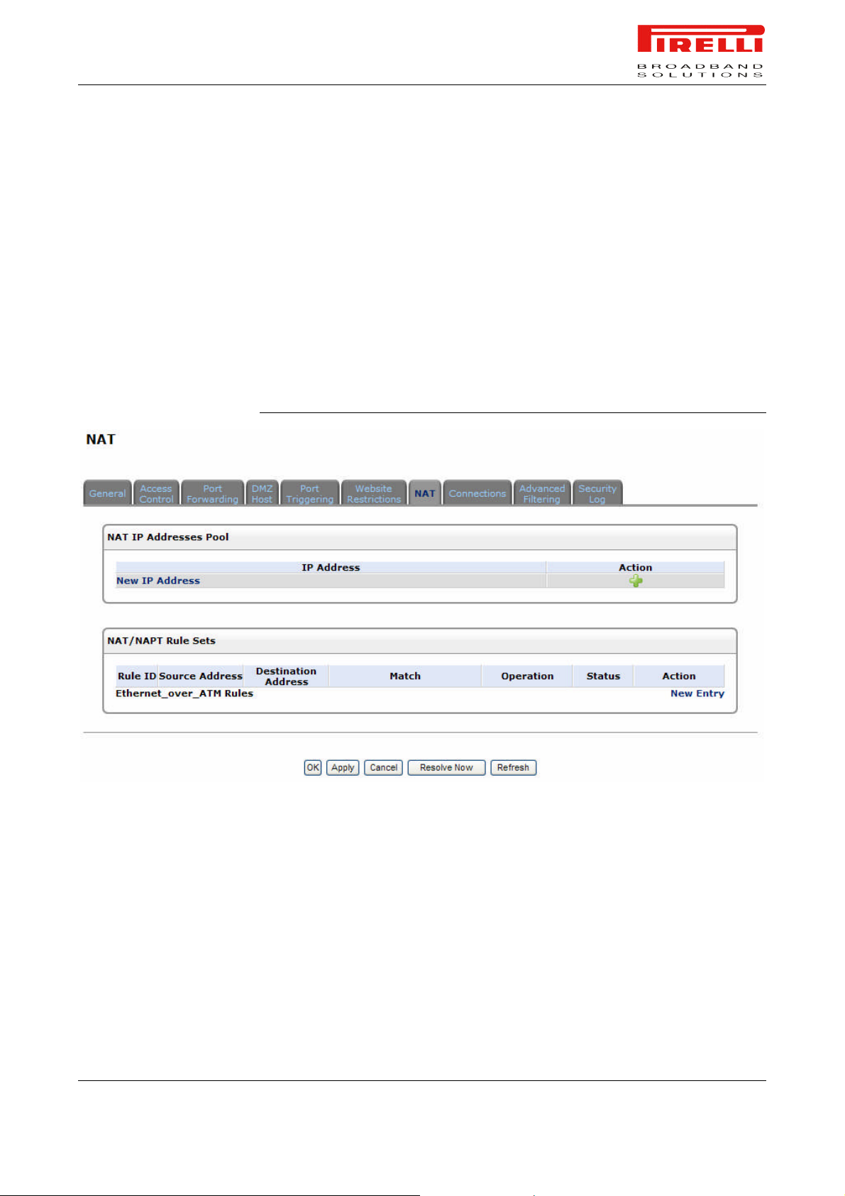
PRG AV4202N
a fixed number of public IP addresses, you can statically define which LAN IP
address will be translated to which NAT IP address and/or ports.
By default, the Router operates in NAPT routing mode. However, you can control your network translation by defining static NAT/NAPT rules. Such rules map
LAN computers to NAT IP addresses.
The NAT/NAPT mechanism is useful for managing Internet usage in your LAN,
or complying with various application demands. For example, you can assign
your primary LAN computer with a single NAT IP address, in order to assure its
permanent connection to the Internet. Another example is when an application
server with which you wish to connect, such as a security server, requires that
packets have a specific IP address - you can define a NAT rule for that address.
FIGURE 7. NAT panel
CONNECTIONS
The connection list displays all the connections that are currently open on the
firewall, as well as various details and statistics. You can use this list to close
undesired connections by clicking their Remove action icons. The basic display
includes the name of the protocol, the different ports it uses, and the direction of
traffic secured.
Press the 'Advanced' button to display a more detailed connection list, which includes the connection's time-to-live, number of kilo-bytes and packets received
and transmitted, the device type and the routing mode.
© (2007) Pirelli Broadband Solutions S.p.A. All Rights Reserved. Proprietary Use Pursuant to Cover Page Instructions.
Security Section OGU 930500275-A1 71
Page 79
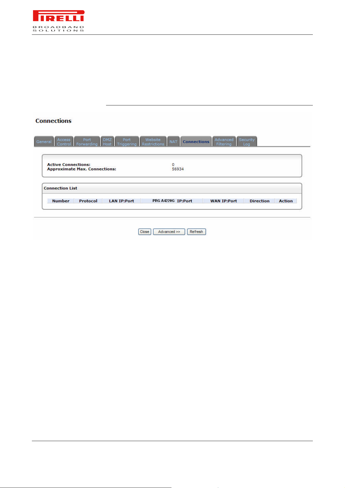
PRG AV4202N
Use the 'Connections Per Page' combo-box to select the number of connections
to display at once. The 'Approximate Max. Connections' value represents the
amount of additional concurrent connections possible.
FIGURE 8. Connections panel
ADVANCED FILTERING
Advanced filtering is designed to allow comprehensive control over the Firewall’s behavior. You can define specific input and output rules, control the order
of logically similar sets of rules and make a distinction between rules that apply
to WAN and LAN devices.
To view Router's advanced filtering options, click 'Advanced Filtering' under the
'Firewall' tab in the 'Services' screen. The 'Advanced Filtering' screen will appear.
This screen is divided into two identical sections, one for 'Input Rule Sets' and
the other for 'Output Rule Sets', which are for configuring inbound and outbound
traffic, respectively. Each section is comprised of subsets, which can be
grouped into three main subjects:
Initial rules - rules defined here will be applied first, on all gateway devices.
Network devices rules - rules can be defined per each gateway device.
Final rules - rules defined here will be applied last, on all gateway devices.
The order of the rules' appearance represents both the order in which they were
defined and the sequence by which they will be applied. You may change this
order after your rules are already defined (without having to delete and then readd them), by using the Move Up and Move Down action icons.
© (2007) Pirelli Broadband Solutions S.p.A. All Rights Reserved. Proprietary Use Pursuant to Cover Page Instructions.
72 OGU 930500275-A1 Security Section
Page 80
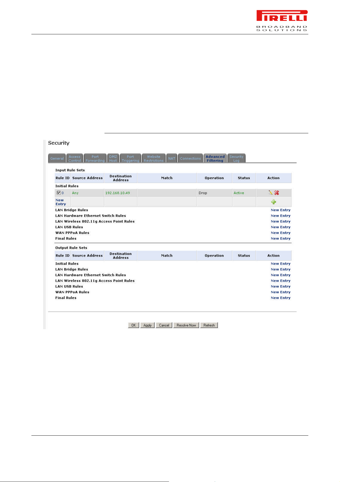
PRG AV4202N
There are numerous rules automatically inserted by the firewall in order to provide improved security and block harmful attacks.
To add an advanced filtering rule, first choose the traffic direction and the device on which to set the rule. Then click the appropriate 'New Entry' link. The
'Add Advanced Filter' screen will appear: this screen is divided into two main
sections, 'Matching' and 'Operation', which are for defining the operation to be
executed when matching conditions apply.
FIGURE 9. Advanced Filtering panel
SECURITY LOG
The Security Log displays a list of firewall-related events, including attempts to
establish inbound and outbound connections, attempts to authenticate through
an administrative interface (Web-based management or Telnet terminal), firewall configuration and system start-up.
To view the security log, click the 'Security Log' tab in the 'Security' management screen. The 'Security Log' screen will appear.
© (2007) Pirelli Broadband Solutions S.p.A. All Rights Reserved. Proprietary Use Pursuant to Cover Page Instructions.
Security Section OGU 930500275-A1 73
Page 81
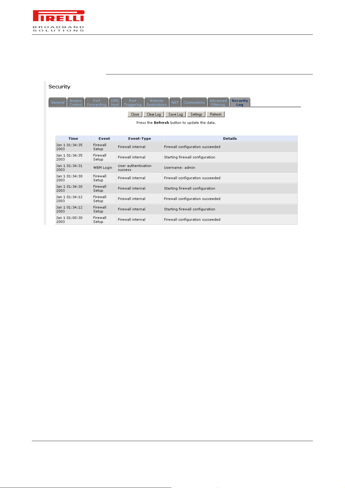
PRG AV4202N
FIGURE 10. Security Log panel
Time. The time the event occurred.
Event. There are five kinds of events:
Inbound Traffic: The event is a result of an incoming packet.
Outbound Traffic: The event is a result of outgoing packet.
Firewall Setup: Configuration message.
WBM Login: Indicates that a user has logged in to WBM.
CLI Login: Indicates that a user has logged in to CLI (via Telnet).
Event-Type. A textual description of the event:
Blocked: The packet was blocked. The message is colored red.
Accepted: The packet was accepted. The message is colored green.
Details. More details about the packet or the event, such as protocol, IP addresses, ports, etc.
To view or change the security log settings, click the 'Settings' button that appears at the top of the 'Firewall Log' screen. The 'Security Log Settings' screen
will appear allowing you to set the types of activities for which you would like to
have a log message generated.
© (2007) Pirelli Broadband Solutions S.p.A. All Rights Reserved. Proprietary Use Pursuant to Cover Page Instructions.
74 OGU 930500275-A1 Security Section
Page 82

LINE SETTINGS
Voice over IP
Section
This chapter will describe the Voice over IP Section accessible from the Home
Page of the PRG AV4202N.
Be aware that any configuration changes could compromise your connectivity.
The Line Settings tab of the VoIP screen defines the phone ports of the Router
and allows you to configure them.
1. Click the 'Voice Over IP' side-bar icon.
2. Click the 'Line Settings' tab, the following screen will appear. Before starting
to make phone calls, you need to configure each line's parameters. You can
manage which telephone is operational by marking the check-box next to it.
© (2007) Pirelli Broadband Solutions S.p.A. All Rights Reserved. Proprietary Use Pursuant to Cover Page Instructions.
Voice over IP Section OGU 930500275-A1 75
Voice over IP Section
Page 83
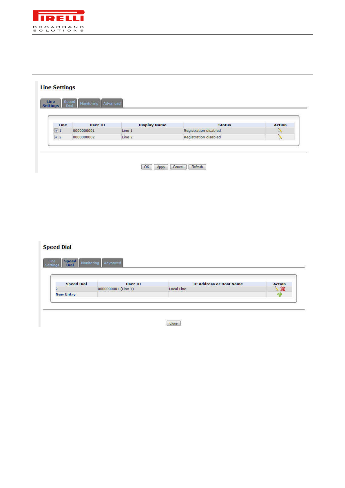
SPEED DIAL
PRG AV4202N
FIGURE 1. Line Settings Panel
3. Click the edit action icon of each line to configure its different parameters.
You can assign speed dial numbers to parties you frequently call. A speed dial
entry must specify a destination which may be of one of three types: proxy, local
line or direct call.
FIGURE 2. Speed Dial Panel
Speed Dial via Proxy. To add a new proxy speed dial entry:
1. Click the 'Speed Dial' tab.
2. Click the 'New Entry' link to add a new speed dial entry. The 'Speed Dial Set-
tings' screen will appear
3. Enter the following parameters:
- Speed Dial: A shortcut number which you will dial to call this party.
- Destination: The entry's destination, in this case a proxy server.
- User ID: Specify the remote party's user ID.
4. Click 'OK' to save the settings.
© (2007) Pirelli Broadband Solutions S.p.A. All Rights Reserved. Proprietary Use Pursuant to Cover Page Instructions.
76 OGU 930500275-A1 Voice over IP Section
Page 84
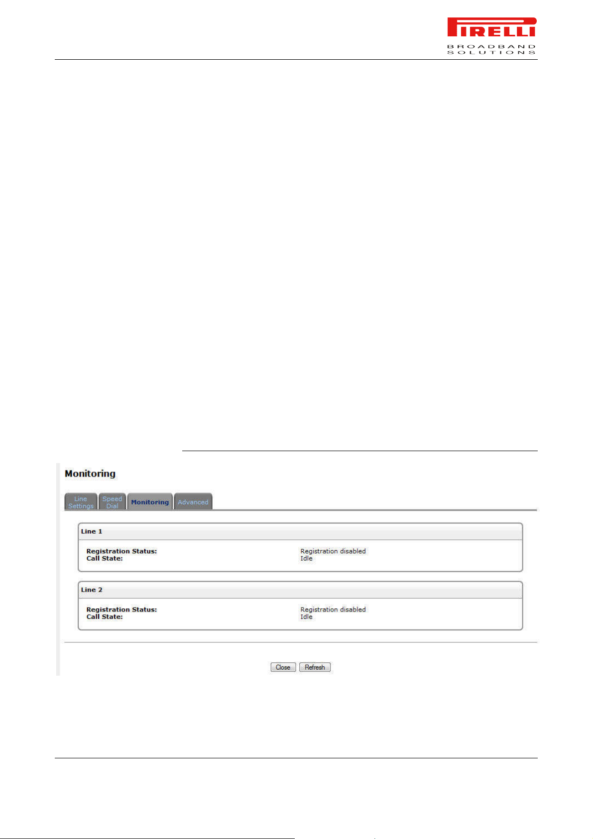
PRG AV4202N
Speed Dial via Local Line. To add a new local line speed dial entry:
1. Click the 'New Entry' link on the 'Speed Dial' tab and select the 'Local Line'
option from the combo-box.
2. Enter the following parameters:
- Speed Dial: A shortcut number which you will dial to call this party.
- Destination: The entry's destination, in this case a local line.
- Line: A combo-box will display your pre-defined local lines. Select the destination line.
3. Click 'OK' to save the settings.
Speed Dial via Direct Call. To add a new direct call speed dial entry:
1. Click the 'New Entry' link on the 'Speed Dial' tab and select the 'Direct Call'
option from the combo-box.
2. Enter the following parameters:
- Speed Dial: A shortcut number which you will dial to call this party.
- Destination: The entry's destination, in this case a direct call.
- User ID: Specify the remote party's user ID.
- IP Address or Host Name: Specify the remote party's IP Address or host
name.
3. Click 'OK' to save the settings.
MONITORING
It is possible to access to the line monitoring page by selecting the ‘Monitoring’
Tab panel: the Registration Status and Call State for each line are shown.
FIGURE 3. Monitoring Panel
© (2007) Pirelli Broadband Solutions S.p.A. All Rights Reserved. Proprietary Use Pursuant to Cover Page Instructions.
Voice over IP Section OGU 930500275-A1 77
Page 85

ADVANCED
PRG AV4202N
The IP Telephony tab of the Voice over IP screen allows configuration of dialing
parameters, VoIP Signaling Protocol, media streaming parameters and codecs.
The following sections describe these various parameters.
© (2007) Pirelli Broadband Solutions S.p.A. All Rights Reserved. Proprietary Use Pursuant to Cover Page Instructions.
78 OGU 930500275-A1 Voice over IP Section
Page 86
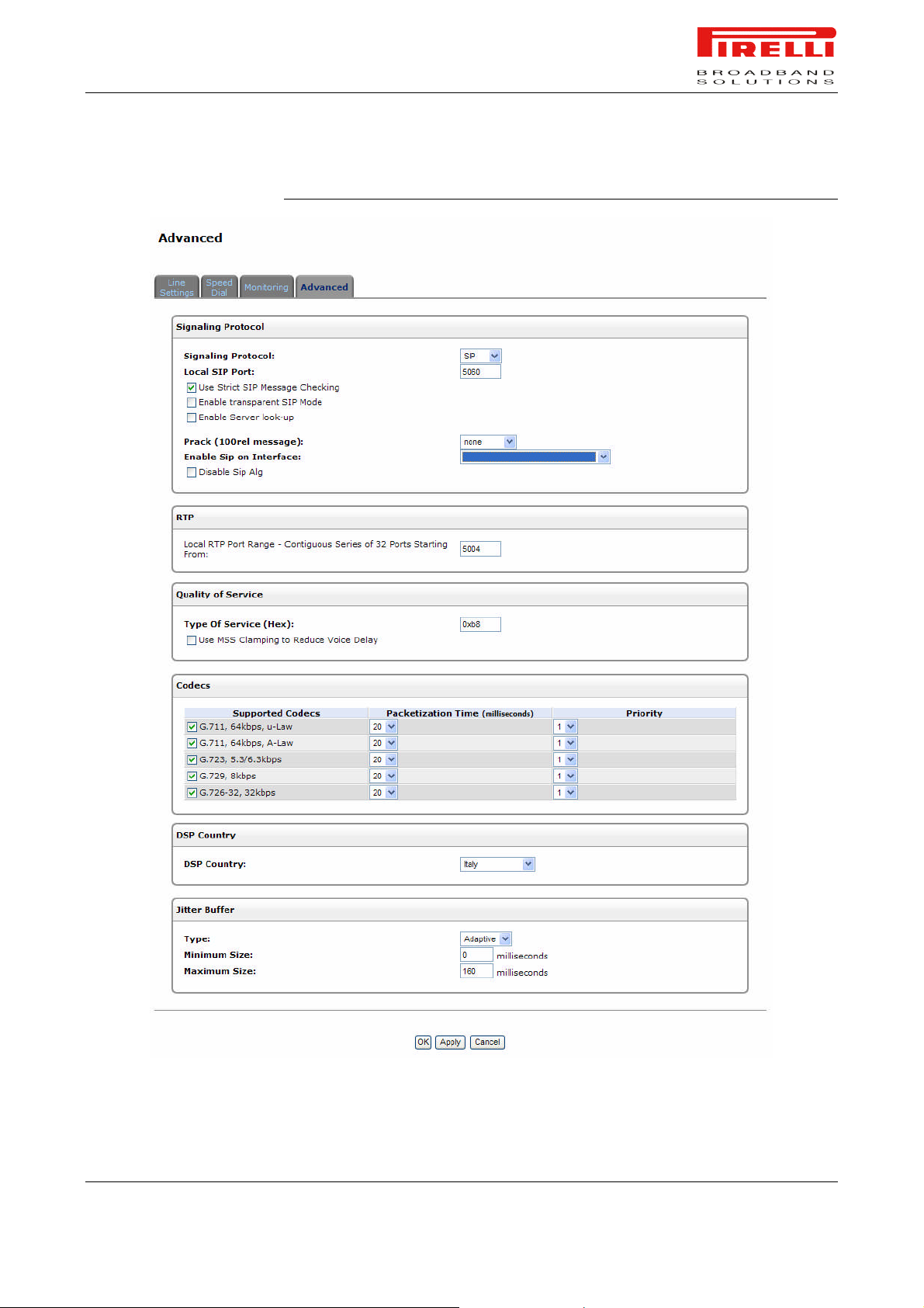
PRG AV4202N
FIGURE 4. Advanced Panel
© (2007) Pirelli Broadband Solutions S.p.A. All Rights Reserved. Proprietary Use Pursuant to Cover Page Instructions.
Voice over IP Section OGU 930500275-A1 79
Page 87

PRG AV4202N
Signaling Protocol. The signaling protocol options available in the combo-box,
are determined by the VoIP stack on your gateway.
A different subset of parameters will become visible with each of the combo-box
choices. To apply the change of protocol you must press either 'OK' or 'Apply'. If
the applied protocol is of another stack, the Router will reboot after you accept
the reboot warning.
RTP. Local RTP Port Range defines the port range for Real Time Protocol
(RTP) voice transport.
Quality of Service. Type of Service (HEX) This is a part of the IP header that
defines the type of routing service to be used to tag outgoing voice packets
originated from the Router. It is used to tell routers along the way that this
packet should get specific QoS. Leave this value as 0XB8 (default) if you are
unfamiliar with the differentiated Services IP protocol parameter.
Codecs. Codecs define the method of relaying voice data. Different codecs
have different characteristics, such as data compression and voice quality. For
example, G.723 is a codec that uses compression, so it is good for use where
bandwidth is limited but its voice quality is not as good compared to other codecs such as the G.711.
Silence Suppression. The Silence Suppression feature allows optimization to
be made when no speech is detected. With this feature enabled, the Router is
able to detect the absence of audio and conserve bandwidth by preventing the
transmission of "silent packets" over the network.
Echo Cancellation. Echo Cancellation is the elimination of reflected signals
(echoes) made noticeable by delay in the network. his also improves the bandwidth of the line. When the delay of a voice call exceeds acceptable limits, the
router will protect the far end from receiving any echo generated at the local end
and sent back through the network.
© (2007) Pirelli Broadband Solutions S.p.A. All Rights Reserved. Proprietary Use Pursuant to Cover Page Instructions.
80 OGU 930500275-A1 Voice over IP Section
Page 88

Parental Control
Section
This chapter will describe the Parental Control accessible from the Home Page
of the PRG AV4202N.
The abundance of harmful information on the Internet is posing a serious challenge for employers and parents alike - "How can I regulate what my employee/child does on the net?" Discus Web-filtering allows parents and employers to regulate, control and monitor Internet access. By classifying and categorizing online content, it is possible to create numerous Internet access policies,
and easily apply them to your home network computers. As a result, you may
keep your children from harm's way by limiting access to adult and violent material, or increase employee productivity by regulating access to non work-related
Internet content.
To effectively filter Web content one must first have a good idea of the kind of
information that is available on the Internet. It is necessary to formulate a landscape of the accessible content, categorize and classify themes and subjects
that may be considered inappropriate.
Discus Parental Control categorization methodology provides an easy and
straightforward method for fine-grained content filtering. The Parental Control
module is constantly updated with URL-based information classified according
to the following categories:
Child protection
Recreation and Entertainment
Personal business
© (2007) Pirelli Broadband Solutions S.p.A. All Rights Reserved. Proprietary Use Pursuant to Cover Page Instructions.
Parental Control Section OGU 930500275-A1 81
Parental Control Section
Page 89

PRG AV4202N
Bandwidth control
Advertisements
Chat
Remote Proxies and Hosting Sites (possibly untrusted sources)
Other
Each category can be expanded into subcategories for better content control.
For instance, the 'Recreation and Entertainment' category is comprised of subcategories such as:
Arts and Entertainment
Education
Games
Hobbies and Recreation
GENERAL OVERVIEW
Discus Parental Control service is provided by "Surf Control", a company specializing in Internet content filtering. Therefore, you must subscribe to this service in order to use this feature. You can subscribe through Discus WBM, as
described in the following section.
1. Under the 'Services; tab, click the 'Parental Control' menu item. The Parental Control's 'General' screen appears.
2. In the 'Activate' section, select the 'Enable Web Content Filtering' check
box, and click 'Apply'. A 'Server Status' section is added.
3. If you have not subscribed yet or your subscription has expired, click the
'Click Here to Initiate and Manage your Subscription' link in the 'Subscribe'
section. The Web filtering subscription site will then be displayed in a new
browser window.
4. Follow the instructions on the site and subscribe for a free trial. You will be
sent a verification email. Click the link in the verification email. Your subscription will be activated soon after clicking the verification link.
5. Return to Discus WBM, and click the 'Parental Control' menu item under the
'Services' tab. The 'Filtering Policy' screen should be displayed with subscription expiry date at the top. If this is not the case, click the 'Advanced
Options' link and then the 'Refresh Servers'button. Wait a few seconds and
repeat this step.
© (2007) Pirelli Broadband Solutions S.p.A. All Rights Reserved. Proprietary Use Pursuant to Cover Page Instructions.
82 OGU 930500275-A1 Parental Control Section
Page 90
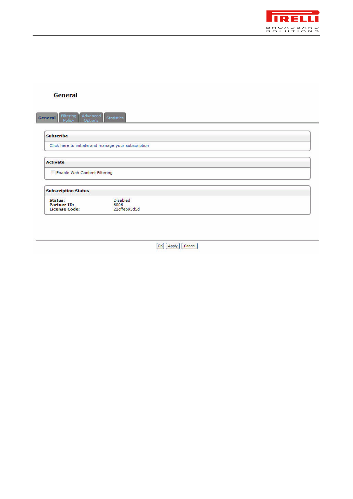
PRG AV4202N
FIGURE 1. General Panel
FILTERING POLICY
A filtering policy defines which sites will be blocked based on their category.
Discus provides four built-in policies:
Home Blocks sites under the 'Child Protection' category.
Employee Blocks sites from non work-related categories.
Block All Blocks all access to the Internet.
Allow All Allows unlimited Internet access.
These policies can be set from the 'Default Filtering Policy' drop-down menu in
the 'Filtering Policy' screen. To view or edit the 'Home' and 'Employee' policies,
click their respective links in this screen. To create your own filtering policy, perform the following:
1. Click the 'Filtering Policy' link under the 'Parental Control' menu item.
2. Click the 'Add a policy' link.
© (2007) Pirelli Broadband Solutions S.p.A. All Rights Reserved. Proprietary Use Pursuant to Cover Page Instructions.
Parental Control Section OGU 930500275-A1 83
Page 91

PRG AV4202N
3. Enter a name and a description for the new policy.
4. Select the content filtering check boxes, which represent content you would
like to block. Selecting a category will automatically select all its subcategories and vice versa. If you would like to make a more refined selection of filtering options, click the plus sign (+) next to each category to display a list of its sub-categories. Note that clicking the minus sign (-) of a
category will only be possible if all its sub-categories are either checked or
unchecked.
5. You can also manually specify a list of Web sites and a list of URL keywords in the provided text fields, to which you can either block or allow access using the corresponding drop-down menu.
6. Click 'OK' to save the settings.
Once you have created different filtering policies, you can either define a default
policy that will be applied to all of your LAN computers, or apply different policies to individual computers separately:
LAN Filtering Policy – To select a default filtering policy for the LAN, select
the policy name from the 'Default Filtering Policy' drop-down menu located
in the 'Filtering Policy' screen, and click Apply.
PC Filtering Policy – To apply separate policies to individual home com-
puters, perform the following:
1. In the 'Filtering Policy' screen (see Figure 7.318), click the 'Add a LAN
Computer' link.
2. Enter the name or IP address of the LAN computer to which you wish to
apply a policy.
3. Select the policy you wish to apply in the 'Policy' drop-down menu.
4. By default, the rule will always be active. However, you can configure
scheduler rules by selecting 'User Defined', in order to define time segments during which the rule may be active. After more than one scheduler rule is defined, the 'Schedule' drop-down menu will allow you to
choose between the available rules.
5. Back in the 'Filtering Policy' screen, use the check box next to the computer name in order to enable or disable its policy.
6. Click 'OK' to save the settings.
© (2007) Pirelli Broadband Solutions S.p.A. All Rights Reserved. Proprietary Use Pursuant to Cover Page Instructions.
84 OGU 930500275-A1 Parental Control Section
Page 92
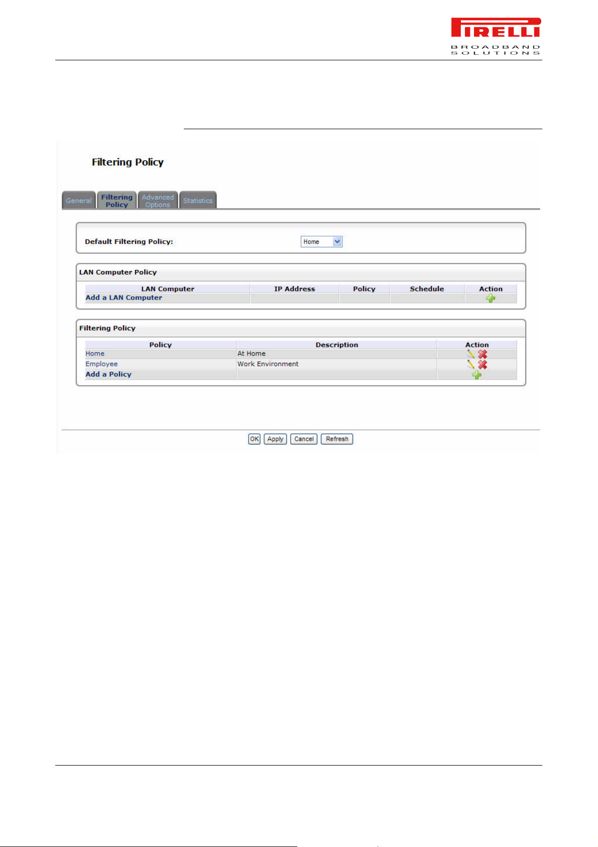
PRG AV4202N
FIGURE 2. Filtering Policy Panel
ADVANCED OPTIONS
© (2007) Pirelli Broadband Solutions S.p.A. All Rights Reserved. Proprietary Use Pursuant to Cover Page Instructions.
Click the 'Advanced Options' link of the 'Parental Control' menu item under the
'Services' tab.
Block All Web Access on Failure to Contact Provider The filtering service
provider is consulted about every site's category in order to decide whether to
allow or block it. If for any reason the provider cannot be consulted, use this
check box to determine whether to block or allow access to all sites.
Redirect URL When a site is blocked, an OpenRG 'Blocked Access' page is
displayed, specifying the requested URL and the reason it was blocked. Use
this field to specify an alternative page to be displayed when a site is blocked.
Parental Control Section OGU 930500275-A1 85
Page 93
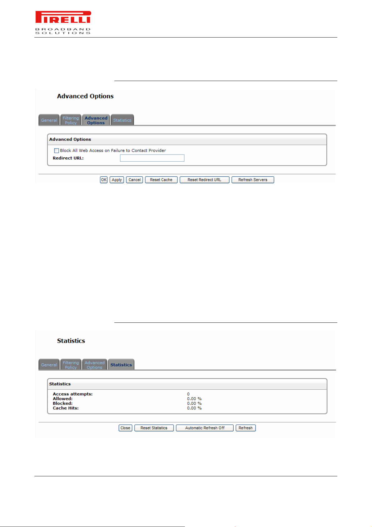
STATISTICS
PRG AV4202N
FIGURE 3. Advanced Options Panel
Click the 'Statistics' link of the 'Parental Control' menu item under the 'Services'
tab.
The 'Statistics' screen monitors content filtering statistics. The statistics include
a record of:
Access attempts
Allowed URLs
Blocked URLs
URLs that were accessed from Cache memory
FIGURE 4. Statistics Panel
© (2007) Pirelli Broadband Solutions S.p.A. All Rights Reserved. Proprietary Use Pursuant to Cover Page Instructions.
86 OGU 930500275-A1 Parental Control Section
Page 94

QoS Section
This chapter will describe the QoS (Quality of Service) Section accessible
from the Home Page of the PRG AV4202N.
Be aware that any configuration changes could compromise your connectivity.
Quality of Service refers to the capability of a network device to provide better
service to selected network traffic. This is achieved by processing higher priority
traffic before lower priority traffic.
As Quality of Service is dependent on the "weakest link in the chain", failure of a
single component along the data path can easily cause a VoIP call or a Video
on Demand (VoD) broadcast to fail miserably.
QoS must therefore obviously be addressed end-to-end.
GENERAL
The 'General' tab provides a Quality of Service "wizard", with which you can
configure your QoS parameters according to predefined profiles, with just a few
clicks. A chosen QoS profile will automatically define QoS rules, which you can
view and edit in the rest of the QoS tab screens.
WAN Devices Bandwidth (Rx/Tx). Before selecting the QoS profile that mostly
suits your needs, select your bandwidth from this combo-box. If you do not see
an appropriate entry, select 'User Defined', and enter your Tx and Rx bandwidths manually.
Tx Bandwidth. Enter your Tx bandwidth in Kbits per second.
Rx Bandwidth. Enter your Rx bandwidth in Kbits per second.
© (2007) Pirelli Broadband Solutions S.p.A. All Rights Reserved. Proprietary Use Pursuant to Cover Page Instructions.
QoS Section OGU 930500275-A1 87
QoS Section
Page 95

PRG AV4202N
QoS Profiles. Select the profile that mostly suits your bandwidth usage. Each
profile entry displays a quote describing what the profile is best used for, and
the QoS priority levels granted to each bandwidth consumer in this profile.
Default: No QoS preferences
P2P User: Peer-to-peer and file sharing applications will receive priority
Triple Play User: VoIP and video streaming will receive priority
Home Worker: VPN and browsing will receive priority
Gamer: Game-related traffic will receive priority
Priority By Host: This entry provides the option to configure which computer
in your LAN will receive the highest priority and which the lowest. If you have
additional computers, they will receive medium priority.
- High Priority Host: enter the host name or IP address of the computer to
which you would like to grant the highest bandwidth priority.
- Low Priority Host: enter the host name or IP address of the computer to
which you would like to grant the lowest bandwidth priority.
© (2007) Pirelli Broadband Solutions S.p.A. All Rights Reserved. Proprietary Use Pursuant to Cover Page Instructions.
88 OGU 930500275-A1 QoS Section
Page 96
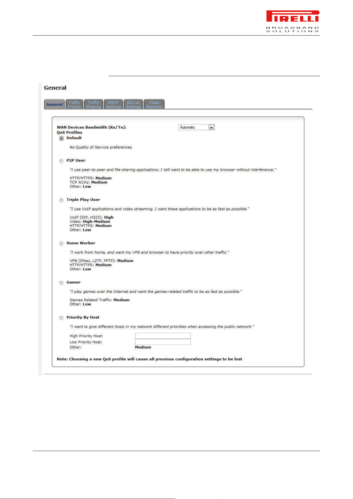
PRG AV4202N
FIGURE 1. General Panel
TRAFFIC PRIORITY
Traffic Priority allows you to manage and avoid traffic congestion by defining inbound and outbound priority rules for each device on your gateway. These rules
© (2007) Pirelli Broadband Solutions S.p.A. All Rights Reserved. Proprietary Use Pursuant to Cover Page Instructions.
QoS Section OGU 930500275-A1 89
Page 97

PRG AV4202N
determine the priority that packets, traveling through the device, will receive.
QoS parameters (DSCP marking and packet priority) are set per packet, on an
application basis.
You can set QoS parameters using flexible rules, according to the following parameters:
Source/destination IP address, MAC address or host name
Device
Source/destination ports
Limit the rule for specific days and hours
The Router supports two priority marking methods for packet prioritization:
DSCP
802.1p Priority
The matching of packets by rules is connection-based, known as Stateful
Packet Inspection (SPI). Once a packet matches a rule, all subsequent packets
with the same attributes receive the same QoS parameters, both inbound and
outbound.
A packet can match more than one rule. Therefore:
The first class rule has precedence over all other class rules (scanning is
stopped once the first rule is reached).
The first traffic-priority (classless) rule has precedence over all other traffic-
priority rules.
There is no prevention of a traffic-priority rule conflicting with a class rule. In
this case, the priority and DSCP setting of the class rule (if given) will take
precedence.
Connection-based QoS also allows inheriting QoS parameters by some of the
applications that open subsequent connections. For instance, you can define
QoS rules on SIP, and the rules will apply to both control and data ports (even if
the data ports are unknown):
SIP
MSN Messenger/Windows Messenger
TFTP
FTP
MGCP
H.323
Port Triggering applications
PPTP
IPSec
© (2007) Pirelli Broadband Solutions S.p.A. All Rights Reserved. Proprietary Use Pursuant to Cover Page Instructions.
90 OGU 930500275-A1 QoS Section
Page 98
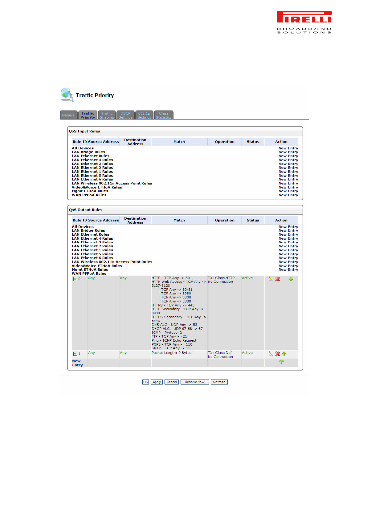
PRG AV4202N
FIGURE 2. Traffic Priority Panel
To set traffic priority rules:
© (2007) Pirelli Broadband Solutions S.p.A. All Rights Reserved. Proprietary Use Pursuant to Cover Page Instructions.
QoS Section OGU 930500275-A1 91
Page 99

TRAFFIC SHAPING
PRG AV4202N
1. Click 'Traffic Priority' under the 'QoS' tab in the 'Services' screen. The 'Traffic
Priority' screen will appear. This screen is divided into two identical sections,
one for 'QoS input rules' and the other for 'QoS output rules', which are for
prioritizing inbound and outbound traffic, respectively. Each section lists all
the gateway devices on which rules can be set. You can set rules on all devices at once, using the 'All devices' entry.
2. After choosing the traffic direction and the device on which to set the rule,
click the appropriate New Entry link. The 'Add Traffic Priority Rule' screen
will appear.
This screen is divided into two main sections, 'Matching' and 'Operation', which
are for defining the operation to be executed when matching conditions apply.
- Matching: Use this section to define the rule's conditions, which are the LAN
computer's parameters to be matched.
- Operation: Set rule priority with Quality of Service.
3. Click 'OK' to save the settings.
Traffic Shaping is the solution for managing and avoiding congestion where a
high speed LAN meets limited broadband bandwidth. A user may have, for example, a 100 Mbps Ethernet LAN with a 100 Mbps WAN interface router. The
router may communicate with the ISP using a modem with a bandwidth of
2Mbps. This typical configuration makes the modem, having no QoS module,
the bottleneck. The router sends traffic as fast as it is received, while its welldesigned QoS algorithms are left unused. Traffic shaping limits the bandwidth of
the router, artificially forcing the router to be the bottleneck.
A traffic shaper is essentially a regulated queue that accepts uneven and/or
bursty flows of packets and transmits them in a steady, predictable stream so
that the network is not overwhelmed with traffic.
While Traffic Priority allows basic prioritization of packets, Traffic Shaping provides more sophisticated definitions. Such are:
Bandwidth limit for each device
Bandwidth limit for classes of rules
Prioritization policy
TCP serialization on a device
Additionally, you can define QoS traffic shaping rules for a default device.
These rules will be used on a device that has no definitions of its own. This enables the definition of QoS rules on Default WAN, for example, and their maintenance even if the PPP or bridge device over the WAN is removed.
© (2007) Pirelli Broadband Solutions S.p.A. All Rights Reserved. Proprietary Use Pursuant to Cover Page Instructions.
92 OGU 930500275-A1 QoS Section
Page 100
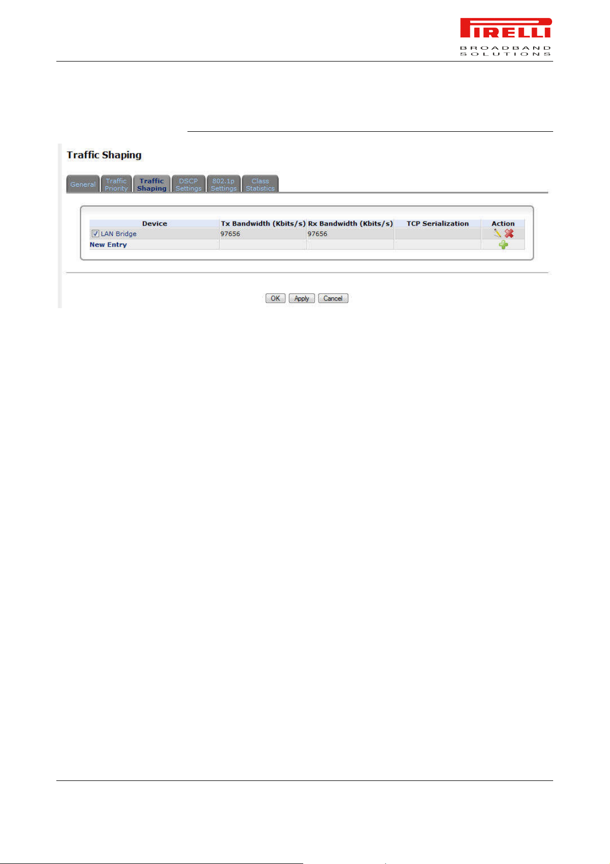
DSCP SETTINGS
PRG AV4202N
FIGURE 3. Traffic Shaping Panel
In order to understand what is Differentiated Services Code Point (DSCP), one
must first be familiarized with the Differentiated Services model.
Differentiated Services (Diffserv) is a Class of Service (CoS) model that enhances best-effort Internet services by differentiating traffic by users, service
requirements and other criteria. Packets are specifically marked, allowing network nodes to provide different levels of service, as appropriate for voice calls,
video playback or other delay-sensitive applications, via priority queuing or
bandwidth allocation, or by choosing dedicated routes for specific traffic flows.
© (2007) Pirelli Broadband Solutions S.p.A. All Rights Reserved. Proprietary Use Pursuant to Cover Page Instructions.
QoS Section OGU 930500275-A1 93
 Loading...