

Page 1
Page 2

Copyright (C) 2006 Pirelli Broadband Solutions S.p.A. All rights reserved. This document contains Pirelli proprietary and
confidential information. No part of thi s document may be copied, repri nted or reproduced in any material form or electronicall y,
whether wholly or in part, and no informa tion con tained herein may be used or disclosed to th ird parties unless under a previous
written agreement with Pirelli Broadband Solutions S.p.A setting forth relevant terms and conditions.
Trademarks:
All terms used in this document that are known to be trademarks or service marks have been noted as such. Pirelli cannot attest
to the accuracy of this information. Other product and corporate names used in this document that may be trademarks or service
marks of other companies are used only for explanation and to the owner’s benefit, without intent to infringe. Use of a term in this
document should not be regarded as affecting the validity of any trademark or servi c e mark.
This publication is subject to change without notice. Pirelli reserves the right to make changes to equi pment design and system
components as well as system documentation and literature as progress in engineering, manufacturing methods, or other
circumstances may warrant.
This publication is intended solely for informational and instructional pur poses. Refer to the above as to its possible uses. It
constitutes neither a contract with the user hereof nor a warranty or guarantee with regard to any of the Pirelli products described
herein nor shall it be construed to grant a license or any other rights un der any proprietary rights to information or material
included herein. Pirelli hereby expressly disclaims any warranty or guarantee, whether express or implied, with regard to items
described herein. Any contract, license, or warranty between Pirelli and the user hereof is created solely by separate legal
documents.
Manual Code: OGU 930500118-A1
Page 3

i
OGU 930500118-A1
(C) (2006) Pirelli Broadband Solutions S.p.A. All Rights Reserved. Proprietary Use Pursuant to Cover Page Instructions.
DISCUS™ Router
CONTENTS
Welcome 1
About this Guide 1
Naming Convention 1
Conventions 1
Introduction 3
Introduction 3
Package Contents 3
Router Advantages 5
Minimum System and Component Requirements 6
Front Panel 6
Rear Panel 7
Hardware Installation 9
Introduction 9
Positioning the Router 9
Installing Micro Filters 10
Powering up the router 11
Connecting the Router 11
Setting Up Your Computer 15
INSTALL Software 15
Ethernet Connection 16
Ethernet Connection >> TCP/IP Protocol Installation 16
Ethernet Connection >> MS Windows 98SE, ME, 2000 17
Ethernet Connection >> MS Windows XP 18
Ethernet Connection >> MAC OS 10.X 20
USB Connection 21
USB Connection >> MS Windows 21
USB Connection >> MAC OS 10.x 22
Router Configuration 25
Introduction 25
Access Control to the web site sections 27
Page 4

ii
OGU 930500118-A1
(C) (2006) Pirelli Broadband Solutions S.p.A. All Rights Reserved. Proprietary Use Pursuant to Cover Page Instructions.
DISCUS™ Router
Device Info Section 29
Summary 29
WAN 30
Statistics >> LAN 30
Statistics >> WAN 31
Statistics >> ATM 32
Statistics >> ADSL 32
Route 34
ARP 35
DHCP 35
Advanced Setup Section 37
WAN 37
LAN 43
DSL 44
Port Mapping 46
NAT Section 49
Virtual Servers 49
Port Triggering 50
DMZ Host 51
Security Section 53
IP Filtering >> Outgoing 53
IP Filtering >> Incoming 54
Routing Section 55
Default Gateway 55
Static Route 56
DNS Section 59
DNS Server 59
Diagnostics Section 61
Management Section 63
Settings Backup 63
Settings Update 64
Settings Restore 64
Page 5

iii
OGU 930500118-A1
(C) (2006) Pirelli Broadband Solutions S.p.A. All Rights Reserved. Proprietary Use Pursuant to Cover Page Instructions.
DISCUS™ Router
System Log 64
Access Control >> Services 65
Access Control >> IP Addresses 65
Access Control >> Passwords 66
Update Software 66
Save / Reboot 67
Troubleshooting 69
Basic Connection Checks 69
Browsing to the Router Configuration Screens 69
Connecting to the Internet 70
Forgotten Password and Reset Configuration to Factory Defaults 70
Frequently Asked Questions 70
Safety Information 72
IP Addressing 74
Technical Specifications 76
Glossary 78
Page 6

iv
OGU 930500118-A1
(C) (2006) Pirelli Broadband Solutions S.p.A. All Rights Reserved. Proprietary Use Pursuant to Cover Page Instructions.
DISCUS™ Router
Page 7

(C) (2006) Pirelli Broadband Solutions S.p.A. All Rights Reserved. Proprietary Use Pursuant to Cover Page Instructions.
1OGU 930500118-A1
Welcome
ABOUT THIS GUIDE This guide describes how to install and configure the DISCUS™
Router. This guide is intended for use by those responsible for installing and setting up network equipment; consequently, it assumes a
basic working knowledge of LANs (Local Area Networks) and Internet Routers.
NAMING CONVENTION Throughout this guide, the DISCUS™ Router is referred to as the
“Router”. Category 5 Ethernet Cables are referred to as Ethernet
Cables throughout this guide.
CONVENTIONS Table 1 and Table 2 list conventions that are used throughout this
guide.
TABLE 1. Notice Icons
Icon Notice Type Description
Information note Information that describes important
features or instructions.
Page 8
DISCUS™ Router
(C) (2006) Pirelli Broadband Solutions S.p.A. All Rights Reserved. Proprietary Use Pursuant to Cover Page Instructions.
2
OGU 930500118-A1
Caution Information that alerts you to potential
loss of data or potential damage to an
application, system, or device.
Warning Information that alerts you to potential
personal injury.
TABLE 2.
Text Conventions
Convention Description
The words “enter” and “type” When you see the word “enter” in this guide, you must type
something, and then press Return or Enter. Do not press
Return or Enter when an instruction simply says “type.”
Keyboard key names If you must press two or more keys simultaneously, the key
names are linked with a plus sign (+). Example:
Press Ctrl+Alt+Del
Words in italics Italics are used to:
• Emphasize a point.
• Denote a new term at the place where it is defined in the
text.
• Identify menu names, menu commands, and software
button names. Examples: “From the Help menu, select
Contents. Click OK.”
TABLE 1.
Notice Icons
Icon Notice Type Description
Page 9

(C) (2006) Pirelli Broadband Solutions S.p.A. All Rights Reserved. Proprietary Use Pursuant to Cover Page Instructions.
3OGU 930500118-A1
Introduction
INTRODUCTION The DISCUS™ Router is designed to provide a cost-effective means
of sharing a single broadband Internet connection between several
wired computers. The Router also provides protection in th e form of
an electronic “firewall” preventing anyone outside of your network
from seeing your files or damaging your computers.
The DISCUS™ Router is an ADSL2+ router, targeted to residential
environments SOHO customers, that provides routed broadband services from a single and modular access point.
The DISCUS™ Router is the ideal solution for:
1. Connecting multiple PCs and Video game consoles;
2. Sharing broadband internet connections between home comput-
ers;
3. Sharing printers and peripherals.
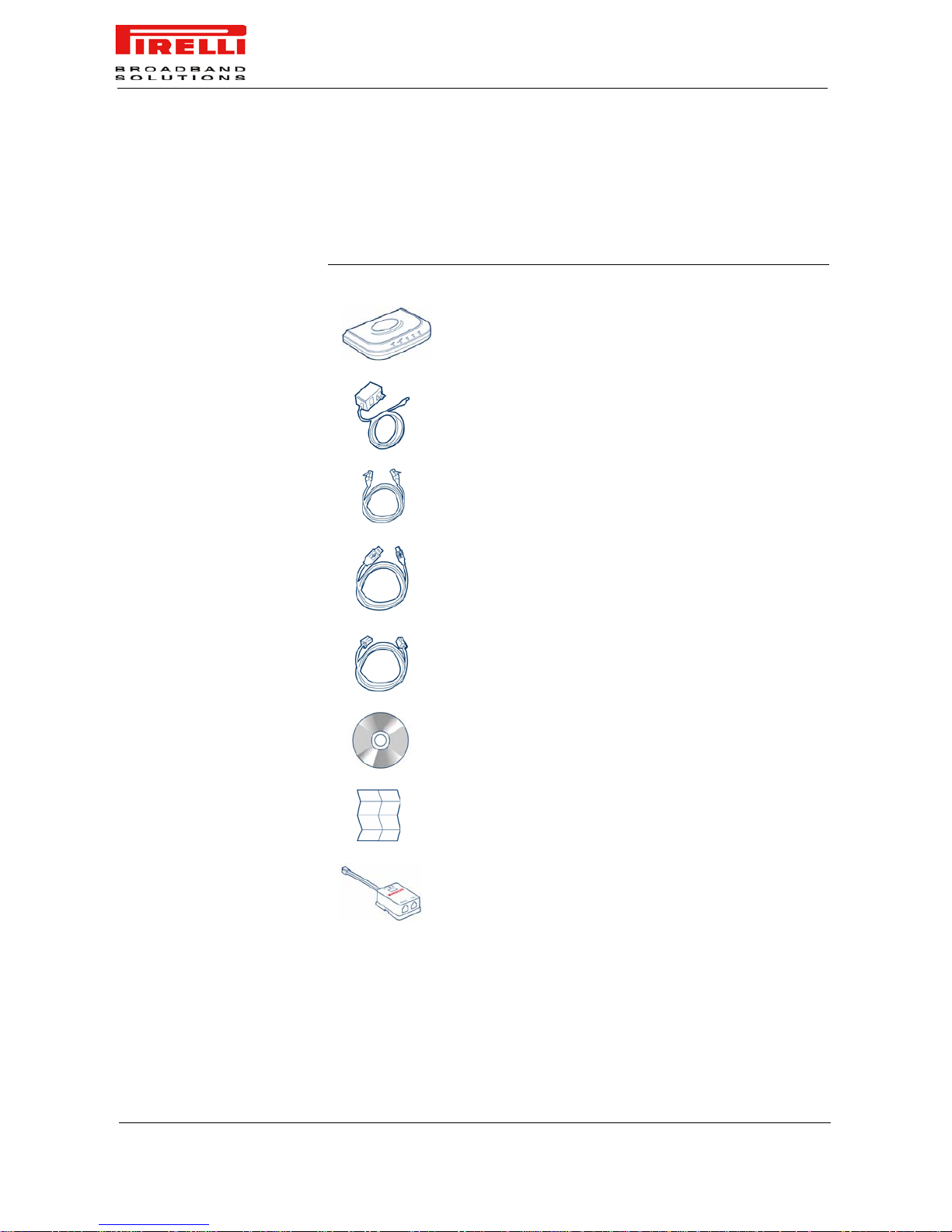
PACKAGE CONTENTS Your new DISCUS™ Router ADSL2+ Router kit contains the related
hardware and software. In it you will find:
1. One DISCUS™ Router unit
2. One Power Supply adapter
3. One ADSL splitter micro filter
4. One USB cable
5. One phone cable
6. One Ethernet cable
7. One installation CD-ROM
Page 10
DISCUS™ Router
4
(C) (2006) Pirelli Broadband Solutions S.p.A. All Rights Reserved. Proprietary Use Pursuant to Cover Page Instructions.
OGU 930500118-A1
8. One Quick Guide
TABLE 1. Kit Material
If any of these items are missing or damaged, please contact your retailer.
Quantity DESCRIPTION
1 DISCUS™ Router
1 Power Supplier
1 Ethernet Cable
1 USB Cable
1 Phone Cord
1 CD-ROM
1Quick Guide
1 ADSL Splitter Micro Filter
Page 11
DISCUS™ Router
(C) (2006) Pirelli Broadband Solutions S.p.A. All Rights Reserved. Proprietary Use Pursuant to Cover Page Instructions.
5
OGU 930500118-A1
It implements an high speed Asymmetric Digital Subscriber Line (ADSL2/2+)
connection to the telephone line on the WAN side, as well several local connectivity technologies on the LAN side:
• Four switched 10/100 Base-TX Ethernet ports
• One Universal Serial Bus 1.1 (USB) connection to a host PC
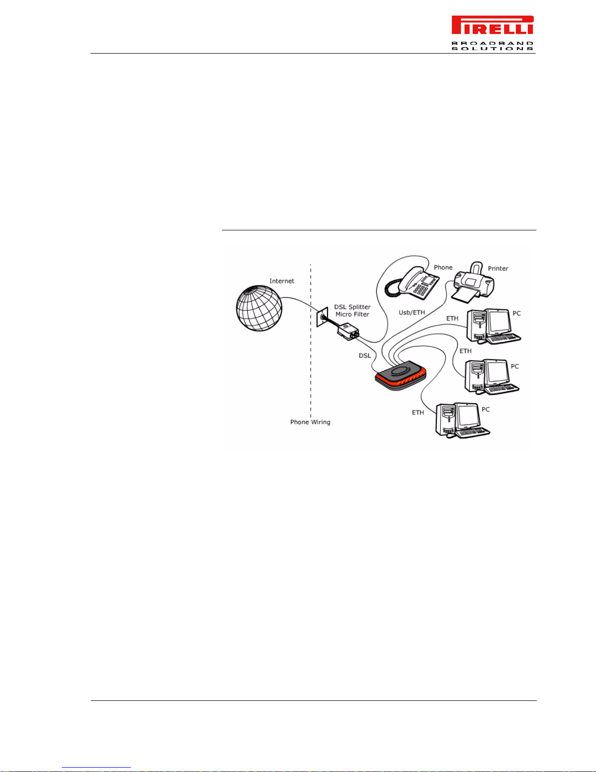
Figure 1 shows a sample network: your Router becomes your connection to the
Internet. Connections can be made directly to the Rout er expanding the number
of computers you can have in your network.
FIGURE 1. Sample Home Network
ROUTER ADVANTAGES
The advantages of the DISCUS™ Router include:
• Shared Internet connec tio n for wired computer s
• No need for a dedicated, “always on” computer serving as your Internet con-
nection
• Cross-platform operation for compatibility with Windows and Macintosh computers (see Technical description for supported platforms).
• Easy-to-use, Web-based setup and configuration
• Centralization of all network address settings (DHCP)
• a Virtual server to enable remote access to Web, FTP, and other services on
your network
• a Security — Firewall protection — against Internet hacker attacks
Page 12
DISCUS™ Router
6
(C) (2006) Pirelli Broadband Solutions S.p.A. All Rights Reserved. Proprietary Use Pursuant to Cover Page Instructions.
OGU 930500118-A1
MINIMUM SYSTEM AND
COMPONENT
REQUIREMENTS
Your DISCUS™ Router requires that the computer(s) and components in your
network be configured with at least the following:
• A computer with the Operating Systems that su pport TCP/IP networking protocols: Windows 98SE, Windows ME, Windows 2000, Windows XP 32bit or
MAC 10.x
• An Ethernet 10Mbps or 10/100 Mbps NIC fo r each computer to be connected
to one of the four Ethernet port at the rear of the Router
• An USB 1.1 port
• At least, 60MB of free hard disk space
• At least, 128 MB of RAM
• Supported Browsers: Internet Explorer 5.5 or higher, Net scape 4.7 or higher
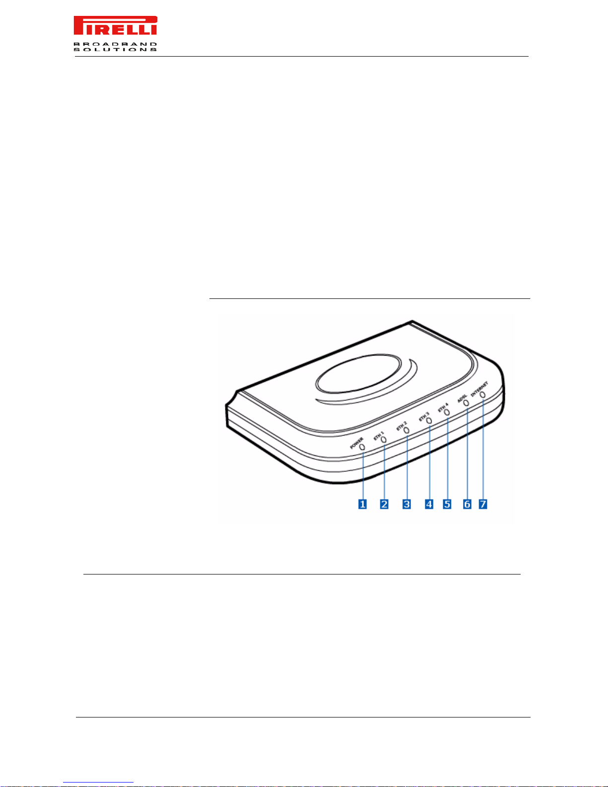
FRONT PANEL The front panel of the Router contains seven indicator lights (LEDs) that help to
describe the state of networking and connection operations.
FIGURE 2. Front Panel LEDs
TABLE 2. LED Description
Ref. LED LED label LED Colour LED Behaviour
1 Power POWER Green Solid Green Power on
Off Power off
2/3/4/5 Ethernet
1/2/3/4 link
ETH 1 / ETH 2 /
ETH 3 / ETH 4
Green Solid Green Ethernet link established
Page 13

DISCUS™ Router
(C) (2006) Pirelli Broadband Solutions S.p.A. All Rights Reserved. Proprietary Use Pursuant to Cover Page Instructions.
7
OGU 930500118-A1
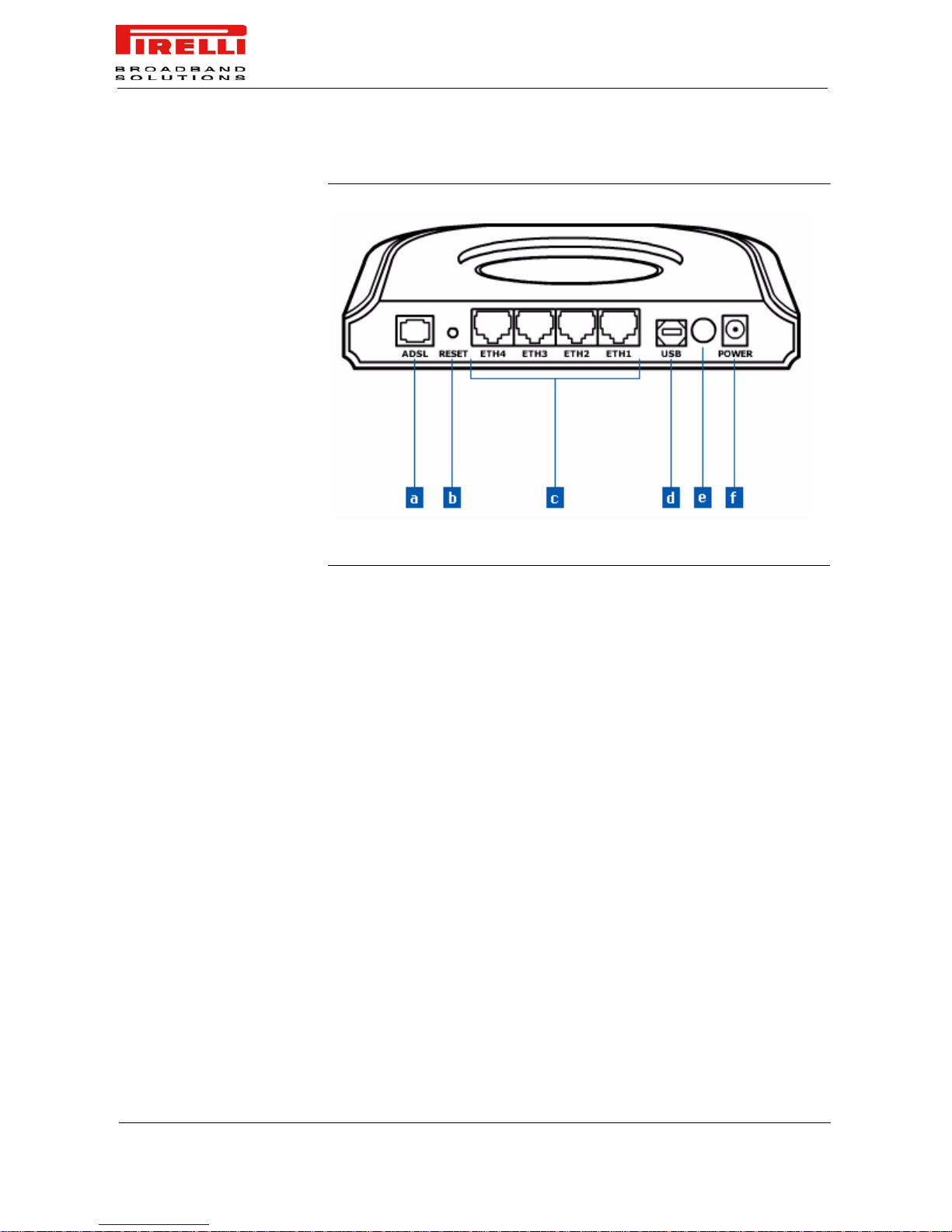
REAR PANEL The rear panel of the Router contains a Reset Configuration to Factory Default
button, a power adapter socket, a Power on button, four LAN ports, one ADSL
port and one USB 1.1 device port.
Flashing Green LAN activity present (traffic in
either directions)
Off No Ethernet link established
6 ADSL line ADSL Off No cable connected
No DSL line active
Green Solid Green DSL connected
Flashing Green DSL attempting synchroniza-
tion
7 Internet INTERNET Green Solid Green WAN IP address available
(PPP active)
off Modem Power off
Red Solid Red WAN IP address not available
(PPP failure)
TABLE 2.
LED Description
Ref. LED LED label LED Colour LED Behaviour
Page 14
DISCUS™ Router
8
(C) (2006) Pirelli Broadband Solutions S.p.A. All Rights Reserved. Proprietary Use Pursuant to Cover Page Instructions.
OGU 930500118-A1
FIGURE 3. Rear Panel LEDs
TABLE 3. Port Description
PORT DESCRIPTION
a Phone ADSL connector (ADSL2/2+)
b Reset Configuration to factory default
c Four Ethernet ports 10/100 Mbps
d USB 1.1 port
e Power button
f Power Adapter Socket
Page 15
(C) (2006) Pirelli Broadband Solutions S.p.A. All Rights Reserved. Proprietary Use Pursuant to Cover Page Instructions.
9OGU 930500118-A1
Hardware
Installation
INTRODUCTION This chapter will guide you through a basic installation of the Router
including:
1. Positioning the DISCUS™ Router
2. Installing Micro Filters
3. Connecting the Router to your network
4. Setting up your computer for networking with the Router
POSITIONING THE ROUTER You should place the Router in such a location to ensure that:
• It is located near an electrical outlet and a phone wall socket
• Water or moisture cannot enter the case of the unit
• It is out of direct sunlight and away from sources of heat
• The cabling is away from power lines, fluorescent lighting fixtures,
and sources of electrical noise such as radios, transmitters and
broadband amplifiers.
Please read carefully the Safety Information in Appendix “A”
A multimedia guided tour on how to connect your device and install the router’s drivers is
available on CD-ROM. It is recommended to follow CD-ROM procedures to easy up device
setup.
Page 16
DISCUS™ Router
(C) (2006) Pirelli Broadband Solutions S.p.A. All Rights Reserved. Proprietary Use Pursuant to Cover Page Instructions.
10
OGU 930500118-A1
INSTALLING MICRO
FILTERS
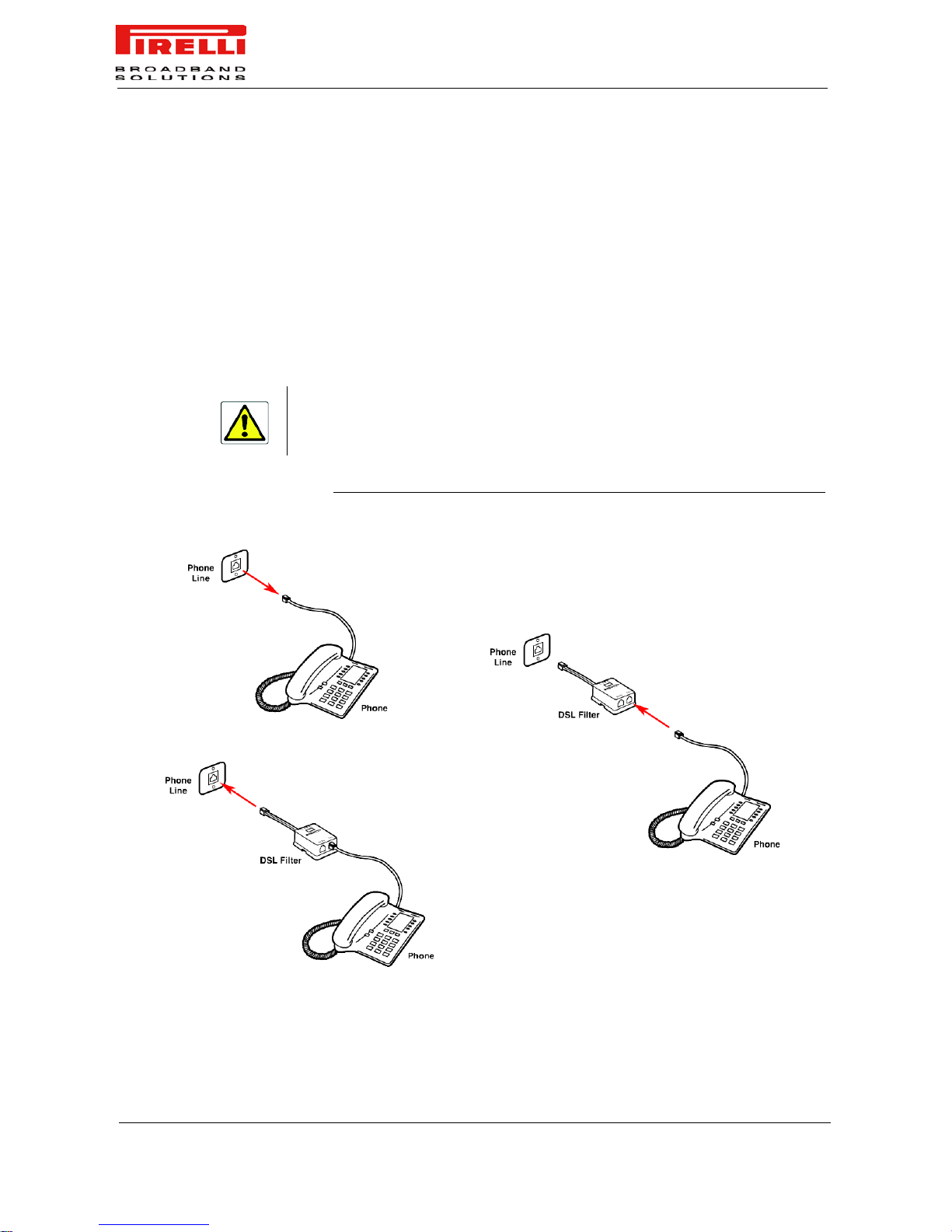
Before beginning installation you must locate devices in your house requiring
a DSL filter such as phones, fax machines, answering machines, dial-up
modems, Satellite TV dialers or monitored security systems and attach a DSL
filter to any one of them sharing the same phone line as your DSL modem.
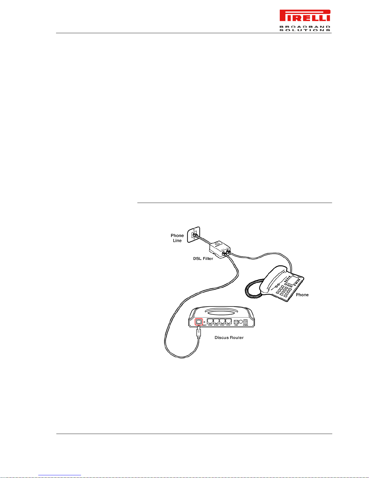
To install DSL filters please follow these steps:
1. Disconnect the phone cable from the telephone wall socket
2. Insert the phone cable into the DSL filte r socket identified with a phone
symbol
3. Insert the DSL filter cable into the telephone wall socket
FIGURE 1. DSL filter installation
You do not need to attach a DSL filter to unused wall sockets.
1
2
3
Page 17
DISCUS™ Router
(C) (2006) Pirelli Broadband Solutions S.p.A. All Rights Reserved. Proprietary Use Pursuant to Cover Page Instructions.
11
OGU 930500118-A1
POWERING UP THE
ROUTER
To power up the Router:
1. Plug the power adapter into the power adapter socket located on the rear
panel of the Router
2. Plug the power adapter into a standard electrical wall socket
3. Press the Power button
4. Wait for the powe r LED to turn steady green
CONNECTING THE ROUTER The first step to install the router is to physically connect it to the telephone
socket and then to connect it to a computer - by means of an Ethernet or an
USB connection - to be able to access the Internet
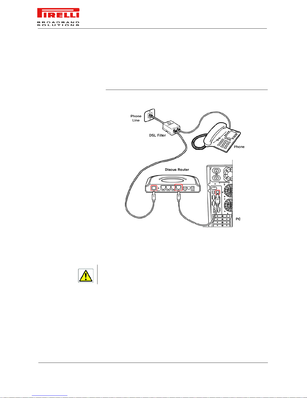
To connect the phone cable:
1. Connect one end of the phone cable into the DSL filter socket identified with
a computer symbol
2. Connect the other end of the phone cable into the DSL socket on the rear of
the Router
FIGURE 2. Phone cable connection
To connect the Ethernet cable:
Page 18
DISCUS™ Router
(C) (2006) Pirelli Broadband Solutions S.p.A. All Rights Reserved. Proprietary Use Pursuant to Cover Page Instructions.
12
OGU 930500118-A1
1. Connect one end of the Ethernet cable into one of the four Ethernet sockets
on the rear of the Router
2. Connect the other end of the ethernet cable into the Ethernet plug of your
computer
FIGURE 3. Ethernet cable connection
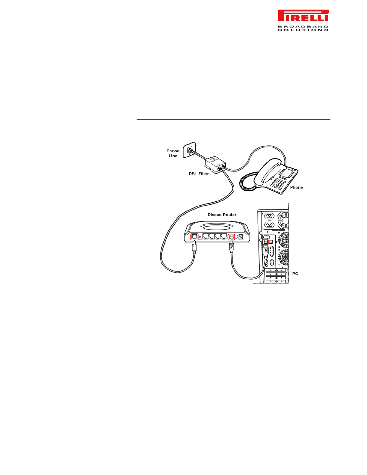
To connect the USB cable:
1. Connect one end of the USB cable into the USB socket of your computer.
2. Launch USB driver setup available on CD-ROM.
To do this, browse till x:\driver folder (where “x” is the CD-ROM drive unit letter); from this folder, according to your Operating System, launch the following executable:
• WINDOWS >> “x:\driver\windows\setup.exe”
• MACOS X >> “x:\driver\macosx\Package.sit”
and follow setup instructions.
Don’t plug the other end of the USB cable until setup software will ask you to do it.
Page 19
DISCUS™ Router
(C) (2006) Pirelli Broadband Solutions S.p.A. All Rights Reserved. Proprietary Use Pursuant to Cover Page Instructions.
13
OGU 930500118-A1
3. The setup software will in vite y ou to plug the other end of the USB cable into
the USB socket on the rear of the Router
(see “USB Connection” ).
To perform for the very first time a USB connection or an Ethernet one to the
Router, it is recommended you to launch the setup application on CD-ROM and
follow the step by step procedure.
FIGURE 4. USB cable connection
Page 20

DISCUS™ Router
(C) (2006) Pirelli Broadband Solutions S.p.A. All Rights Reserved. Proprietary Use Pursuant to Cover Page Instructions.
14
OGU 930500118-A1
Page 21

(C) (2006) Pirelli Broadband Solutions S.p.A. All Rights Reserved. Proprietary Use Pursuant to Cover Page Instructions.
15OGU 930500118-A1
Setting Up Your
Computer
The Router has the ability to dynamically allocate network addresses
to the computers on your network, using DHCP. However, your computers need to be configured correctly for this to take place. To
change the configuration of your computers to allow this, follow the
instructions in this chapter.
INSTALL SOFTWARE The very first time you set up your computer, we recommend you to
use setup software available on CD-ROM.
Setup software offers a guided product tour, a step by step hardware
installation guide, a software installation guide and setup depending
on your connection choice (USB or ETHERNET) and a driven user
registration with DSL Internet connection line check.
Setup software setup allows, for supported Microsoft Windows Operating Systems, to setup automatically your computer Ethernet settings.
To launch Setup, insert Setup software CD-ROM in CD-ROM unit: if
the autoplay function is enabled it will start automatically, otherwise
click once on the “Run...” item in “Start” menu. In the opened panel
type “x:\install.exe” where x is your CD-ROM drive letter.
Before installing the DISCUS™ Router software please close all applications to avoid any
conflict.
Page 22

DISCUS™ Router
(C) (2006) Pirelli Broadband Solutions S.p.A. All Rights Reserved. Proprietary Use Pursuant to Cover Page Instructions.
16
OGU 930500118-A1
ETHERNET CONNECTION In case you already established a connection with your Router a first time and/
or you do need to set up manually a connection to your Router, please follow
the instructions described in this chapter. You will be guided to set up an Ethernet connection to the Router. To do so, first you have to verify the existence of a
TCP/IP protocol stack and, then, according to your Operating System, to establish an Ethernet connection to it. This connection will require you to enable your
computer to receive from the Router its own IP Address automatically: in such a
case, the Router acts like the DHCP server in your local network.
ETHERNET CONNECTION
>> TCP/IP PROTOCOL
INSTALLATION
This procedure requires the TCP/IP protocol installed on your computer. Refer
to the following paragraphs and to your Windows and MacOS operating systems manuals.
Microsoft Windows 98SE, ME, 2000.
1. Put in the CD-ROM drive your Windows installation CD-ROM
2. Starting from Start -> Settings -> Control Panel or Start -> Control Panel
depending on the configuration of your computer
3. Make a double click on the Network and Dial-up Connections icon
4. Select the interested Network Adapter icon and from the contextual menu,
do select the Properties item
5. If the Internet Protocol (TCP/IP) component is not checked you must enable
it by checking the Internet Protocol (TCP/IP) item; otherwise, if it is not listed,
you must install it by selecting the Install... button
6. Choose the Protocol Network component and click on the Add.. button
7. In the Select Network Protocol panel, do choose Internet Protocol (TCP/IP)
and the OK button
8. Af ter rebooting, y ou' re ready to configure t he TCP/IP setting, as described in
the following paragraphs
Microsoft Windows XP.
TCP/IP stack is considered a core component of the operating system, so it
cannot be installed or uninstalled. You must check in this case that Internet Protocol (TCP/IP) is enabled. To do so, follow hese steps:
1. Starting from Start -> Settings -> Control Panel or Start -> Control Panel
depending on the configuration of your computer
2. Make a double click on the Network Connections icon
3. Select the Network Adapter icon and from the contextual menu, do select the
Properties item
4. In the General TAB panel, verify that Internet Protocol (TCP/IP) item is
checked; if not, do check it and click on the OK button
Apple MacOS 10.x.
TCP/IP is installed on a MacOS system as part of Open Transport.
Page 23
DISCUS™ Router
(C) (2006) Pirelli Broadband Solutions S.p.A. All Rights Reserved. Proprietary Use Pursuant to Cover Page Instructions.
17
OGU 930500118-A1
ETHERNET CONNECTION
>> MS WINDOWS 98SE, ME,
2000
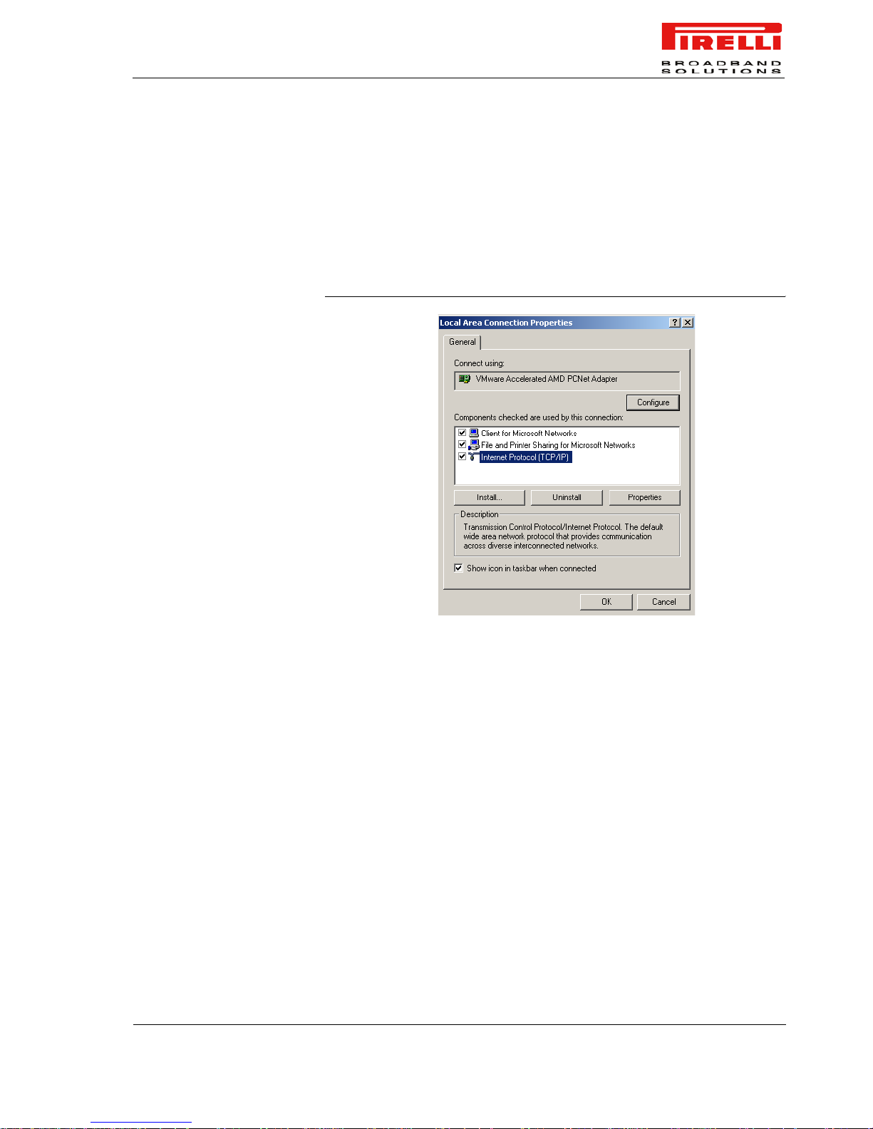
To configure TCP/IP on these Operating Systems follow these steps:
1. Select Start -> Settings -> Control Panel and make a doubl e clic k on the Net-
work and Dial-up Connection icon.
2. Select the adapter card interested by TCP/IP configur ation and then select
the Properties item from its contextual menu
3. Select Internet Protocol (TCP/IP) item then click on Properties button
FIGURE 1. Local Area Connection Properties
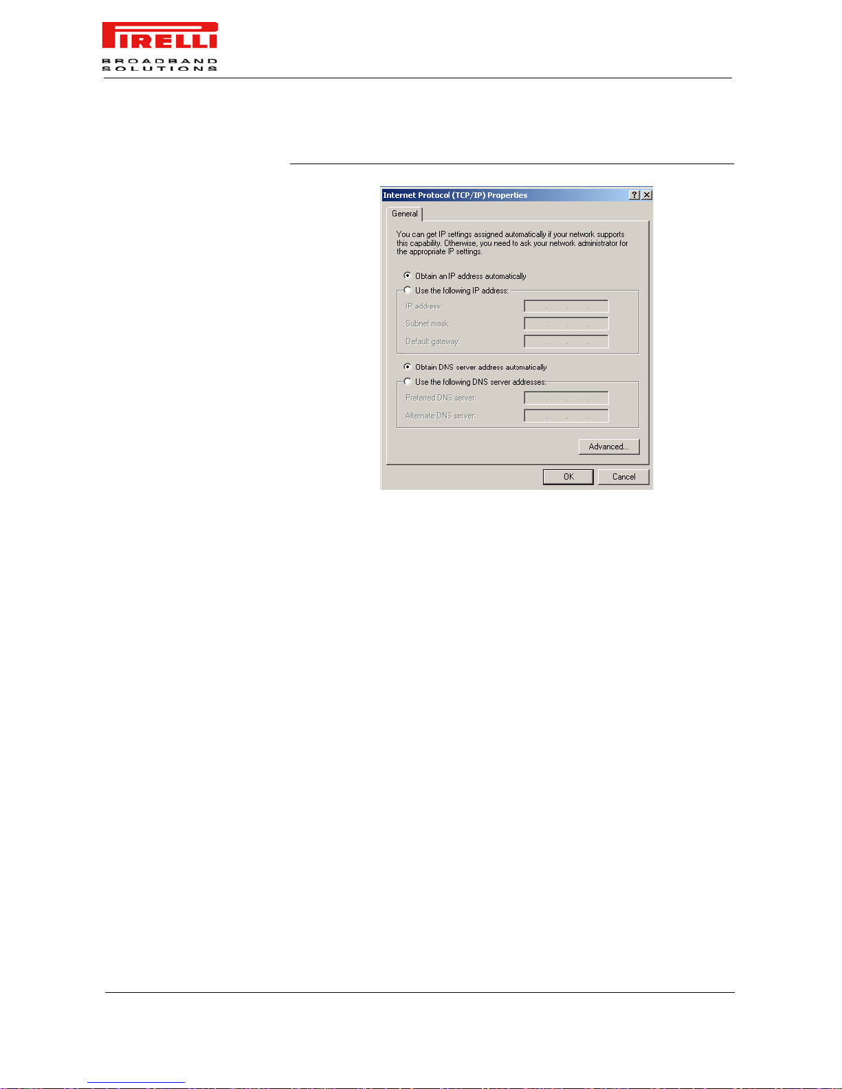
4. Select the General TAB panel, then check the Obtain an IP address auto-
matically and Obtain DNS server address automatically radio buttons. Click
on OK button.
Page 24
DISCUS™ Router
(C) (2006) Pirelli Broadband Solutions S.p.A. All Rights Reserved. Proprietary Use Pursuant to Cover Page Instructions.
18
OGU 930500118-A1
FIGURE 2. Internet Protocol (TCP/IP) Properties
5. A system reboot will be required to make the changes real.
ETHERNET CONNECTION
>> MS WINDOWS XP
To configure TCP/IP on MS Windows XP Operating Syst em follow these steps:
1. Select Start -> Settings -> Control Panel and make a double click on the Net-
work Connections icon.
2. Select the adapter card interested by TCP/IP configur ation
3. Select the Properties item from the contextual Adapter Card menu
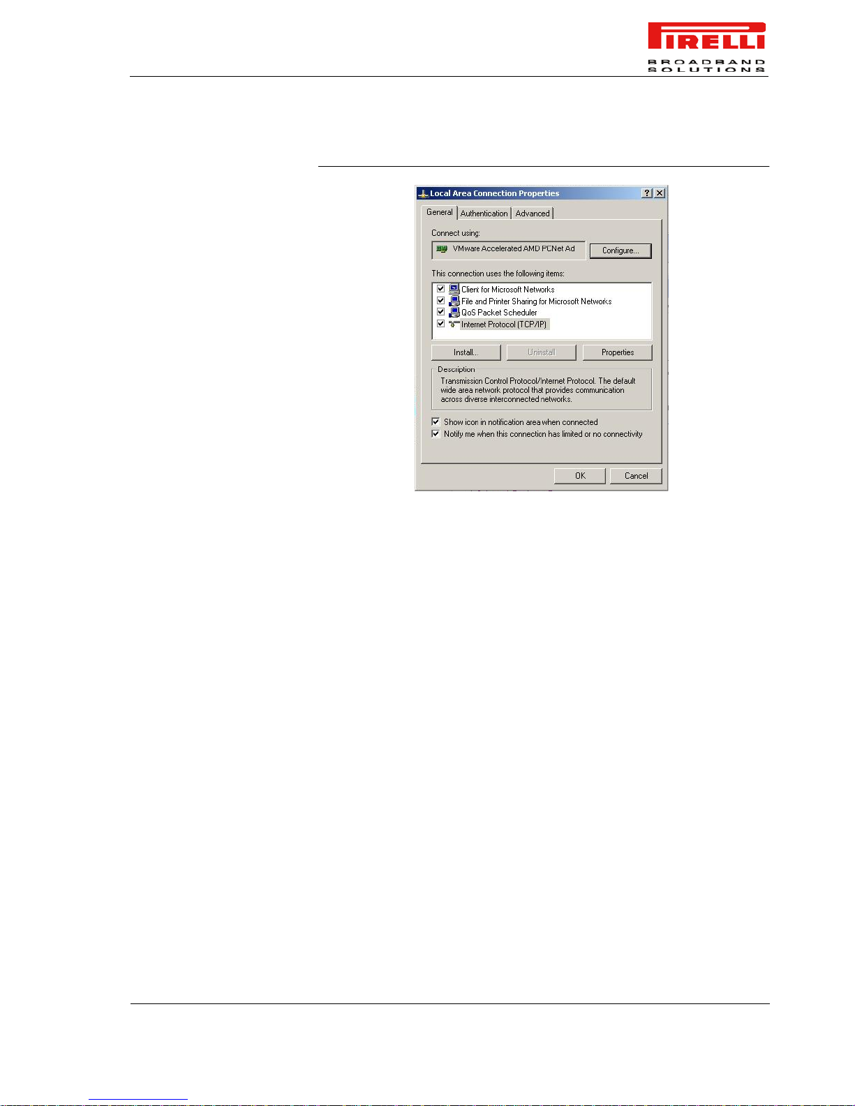
4. Select in the General TAB panel, the Internet Protocol (TCP/IP) item and
then click on Properties button.
Page 25
DISCUS™ Router
(C) (2006) Pirelli Broadband Solutions S.p.A. All Rights Reserved. Proprietary Use Pursuant to Cover Page Instructions.
19
OGU 930500118-A1
FIGURE 3. Local Area Connection Properties
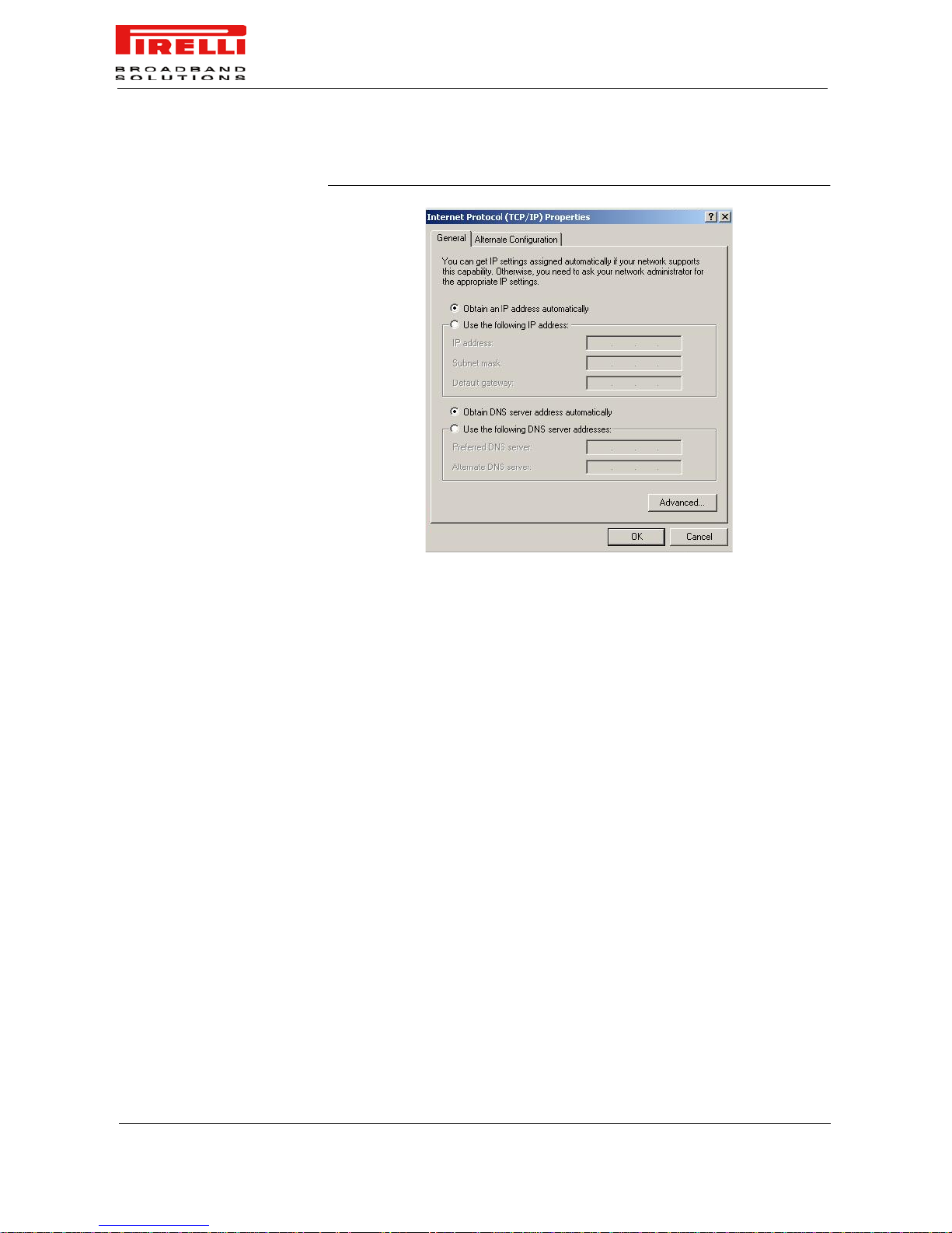
5. In the General TAB panel, check the Obtain an IP address automatically
radio button and the Obtain DNS server address automatically radio button.
Click on OK button.
Page 26
DISCUS™ Router
(C) (2006) Pirelli Broadband Solutions S.p.A. All Rights Reserved. Proprietary Use Pursuant to Cover Page Instructions.
20
OGU 930500118-A1
FIGURE 4. Internet Protocol (TCP/IP) Properties
ETHERNET CONNECTION
>> MAC OS 10.X
To configure TCP/IP on MAC OS 10.x follow these steps:
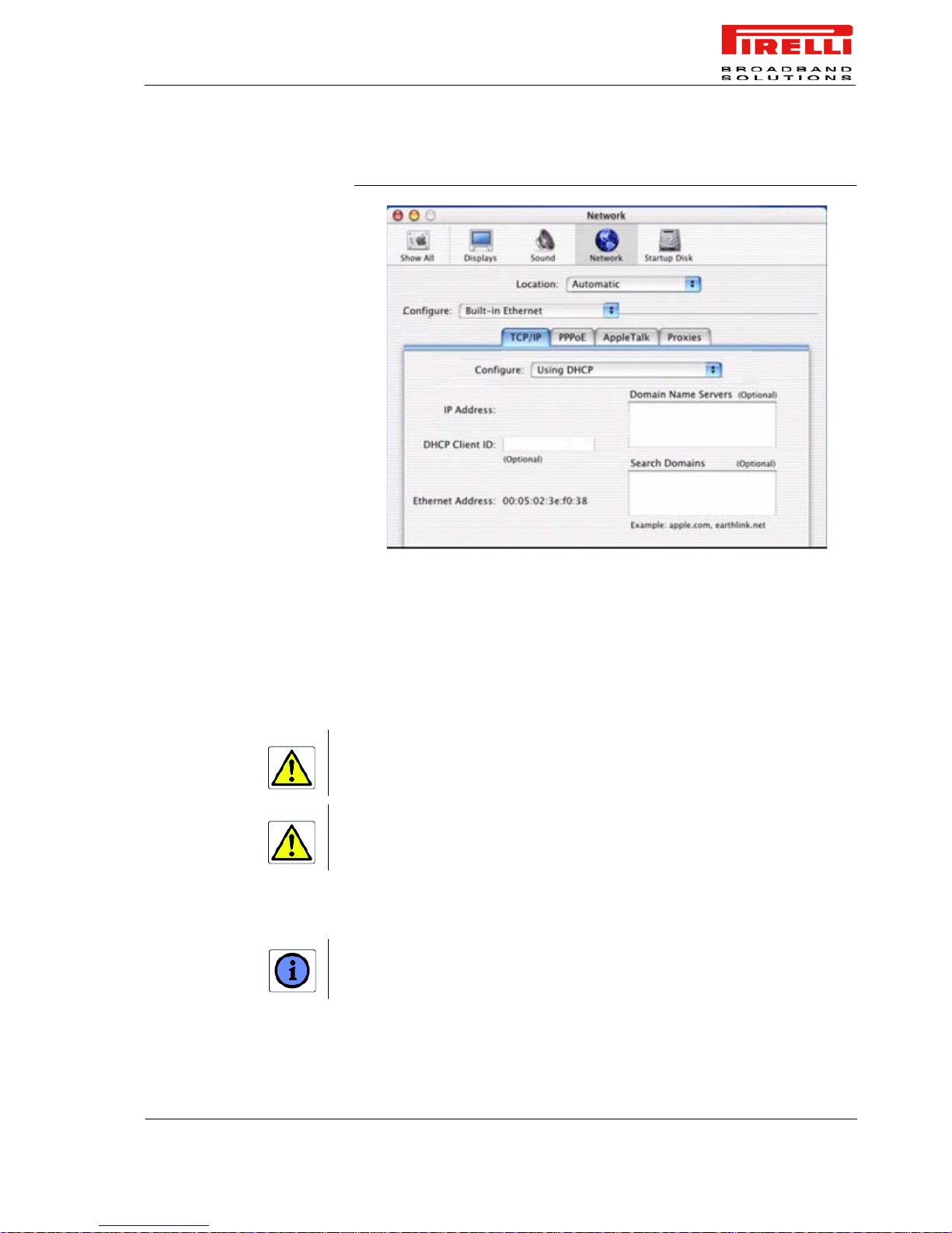
1. Open the Apple Menu -> System Preferences and select Network.
2. From the Show drop down list, according to the type of connection used,
select Built-in Ethernet.
3. Select the TCP/IP tab.
4. Select DHCP from the Configure pop-up menu to have a dynamic IP
address.
Page 27
DISCUS™ Router
(C) (2006) Pirelli Broadband Solutions S.p.A. All Rights Reserved. Proprietary Use Pursuant to Cover Page Instructions.
21
OGU 930500118-A1
FIGURE 5. Network panel on MAC OS 10.x
5. Click Apply Now.
6. Click on the Register button to save the changes in the Control Panel.
7. Enter http://192.168.1.1/ in the address bar of your browser to open the
DISCUS™ Router Home Page.
USB CONNECTION To connect your first Computer to the DISCUS™ Router using USB port, you
have to install the Router’s USB driver on your computer.
USB CONNECTION >> MS
WINDOWS
Before connecting the USB Cable to the USB Port of the DISCUS™ Router you have to run
the setup software and to follow the instructions. Connect the USB Cable only when required
from the installation software.
Only one Windows or Macintosh computer can be directly connected to the DISCUS™
Router using the USB connection. Additional computers can be added to your network using
the Ethernet connections.
Using Windows 98SE the system could require the Operating System installation CD-ROM.
Page 28
DISCUS™ Router
(C) (2006) Pirelli Broadband Solutions S.p.A. All Rights Reserved. Proprietary Use Pursuant to Cover Page Instructions.
22
OGU 930500118-A1
1. Browse the Setup CD-ROM and install the USB Windows driver selecting
the folder x:\driver\windows (where x is the CD-ROM driver unit).
2. Make a double click on setup.exe file to start driver setup procedure.
3. When the message “NOW CONNECT THE USB CABLE” should appear,
connect the USB cable from a free USB port of the computer to the
DISCUS™ Router USB port.
4. Enter http://192.168.1.1/ in the address bar of your browser to open the
DISCUS™ Router Home Page.
USB CONNECTION >> MAC
OS 10.X
1. Browse the CD-ROM and install the USB MAC OS 10.x selecting the folder
x:\driver\macosx (where x is the CD-ROM drive unit).
2. Make a double click on the Package.sit zipped file to start the unzip.
3. Select the folder Macintosh HD:osxdrv:Install USB ADSL.
4. Make a double click on the install script file.
5. Restart the computer clicking on the Restart button.
6. When appear the message “NOW CONNECT THE USB CABLE”, connect
the USB cable from a free USB port of the computer to the DISCUS™
Router USB port.
7. Verify that your co mputer is configur ed to obtain an IP address au tomatically
via DHCP mode, following the next steps.
8. Open the Apple Menu -> System Preferences and select Network.
9. From the Show drop down list, according to the type of connection used,
select Built-in USB ADSL.
10. Select the TCP/IP tab.
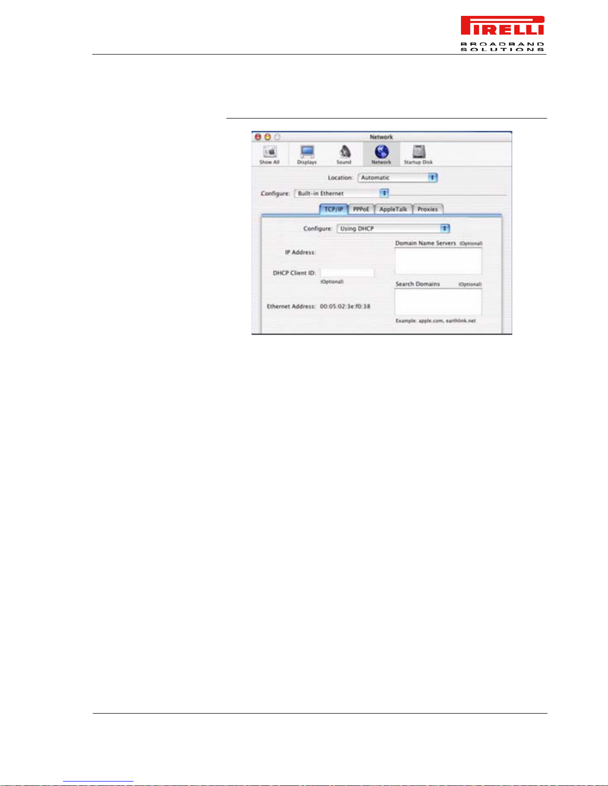
11. Select Using DHCP from the Configure pop-up menu to have a dynamic IP
address.
If the system requires the path, select the hard disk main folder, normally named Macintosh
HD.
Page 29
DISCUS™ Router
(C) (2006) Pirelli Broadband Solutions S.p.A. All Rights Reserved. Proprietary Use Pursuant to Cover Page Instructions.
23
OGU 930500118-A1
FIGURE 6. Network Pa nel
12. Click Apply Now.
13. Click on the Register button to save the changes in the Control Panel.
14. Enter http://192.168.1.1/ in the address bar of your browser to open the
DISCUS™ Router Home Page.
Page 30

DISCUS™ Router
(C) (2006) Pirelli Broadband Solutions S.p.A. All Rights Reserved. Proprietary Use Pursuant to Cover Page Instructions.
24
OGU 930500118-A1
Page 31

(C) (2006) Pirelli Broadband Solutions S.p.A. All Rights Reserved. Proprietary Use Pursuant to Cover Page Instructions.
25OGU 930500118-A1
Router
Configuration
INTRODUCTION The Router setup program is web based, which means that it is
accessed through your web browser.
To access to Router’s web server:
1. Launch your web browser on the computer
2. Enter the following URL in the location or address field of your
browser: http://192.168.1.1
Access to DSL router configuration pages is controlled through three
user accounts: admin, support and user:
1. “admin" has unrestricted access to change and view configuration
of the DSL Router.
2. "support" is used to allow an ISP technician to access DSL Route r
for maintenance and to run diagnostics.
3. "user" can access the DSL Router, view configuration settings
and statistics, as well as, update the router's software.
You will be asked to insert a username and a password (according to
the above listed user accounts): insert them to access to Router’s
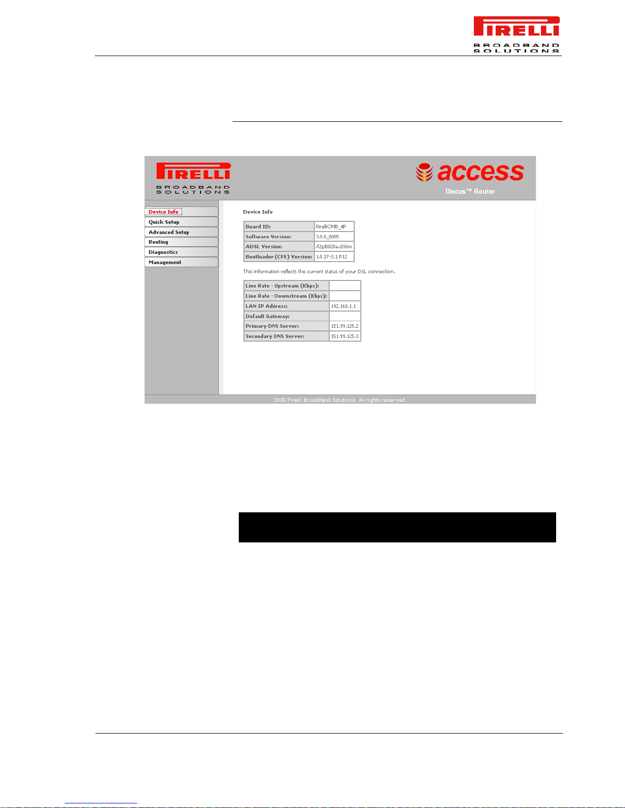
configuration panels. The main page, upon Router access, will be
opened as shown in Figure 1.
The Router comes with a default IP address (192.168.1.1). If you change it, please take note
of the new Router’s IP address, otherwise a “Reset Configuration to Factory Default” operation should be done to be able to access again to the Router.
Page 32

DISCUS™ Router
(C) (2006) Pirelli Broadband Solutions S.p.A. All Rights Reserved. Proprietary Use Pursuant to Cover Page Instructions.
26
OGU 930500118-A1
The main page contains a menu on the left - always available in all the web
pages which is the starting point for any Router’s configuration.
The complete menu has the following main items:
1. Device Info: it allows to access to Device Information and Statitics.
2. Quick Setup: if no WAN interface does exist, this menu will be available.
3. Advanced Setup: it allows the access to the advanced configuration pan-
els.
4. NAT: it allows to configure NAT parameters (available only if a WAN inter-
face already available)
5. Security: it configures IP filtering parameters (available only if a WAN
interface already available)
6. Routing: it allows to configure the default gateway or the static routings
7. DNS: to configure the DNS server parameters (available only if a WAN
interface already available)
8. Diagnostics: a menu to show and run diagnostic test for t roub lesho oting or
system behaviour analysis.
9. Management: it allows to define Router parameters devoted to user
access, log management, Router’s time, Backup Router’s configuration,
etc.
In order to submit the changes of most of device parameters you have to click the Save/
Apply button to save permanently your changes. In some cases, the reboot of the Router is
required.
Page 33
DISCUS™ Router
(C) (2006) Pirelli Broadband Solutions S.p.A. All Rights Reserved. Proprietary Use Pursuant to Cover Page Instructions.
27
OGU 930500118-A1
FIGURE 1. Router’s Main Page
ACCESS CONTROL TO THE
WEB SITE SECTIONS
According to your profile permission (admin, support or user) some information
cannot be available. In case no WAN inter face is already confugured, the Quick
Setup menu with its own dedicated options will be available .
Table 1 shows a map of panels according to user rights and WAN state.
TABLE 1. Access control to web site sections
Section / Sub Section admin user
no WAN
configured
Device Info
Summary x x x
WAN x x x
Statistics
LAN x x x
WAN x x x
ATM x x x
ADSL x x x
Route x x x
Page 34

DISCUS™ Router
(C) (2006) Pirelli Broadband Solutions S.p.A. All Rights Reserved. Proprietary Use Pursuant to Cover Page Instructions.
28
OGU 930500118-A1
ARP x x x
DHCP x x x
Quick Setup x x
Advanced Setup
WAN x x
LAN x x
DSL x x
Port Mapping x
NAT x
Virtual Servers x
Port Triggering x
DMZ Host x
Security x
IP Filtering x
Outgoing x
Incoming x
Routing x
Default Gateway x x
Static Route x x
DNS x
DNS Server x
Diagnostics x x x
Management
Settings x
Settings Backup x x
Settings Update x x
Settings Restore x x
System Log x x x
Access Control x
Services x x
IP Addresses x x
Passwords x x
Update Software x x x
Save/Reboot x x
TABLE 1.
Access control to web site sections
Section / Sub Section admin user
no WAN
configured
Page 35
(C) (2006) Pirelli Broadband Solutions S.p.A. All Rights Reserved. Proprietary Use Pursuant to Cover Page Instructions.
29OGU 930500118-A1
Device Info
Section
This chapter will describe the Device Info Section accessible from
the Home Page of the DISCUS™ Router upon user au then tication t o
the Router.
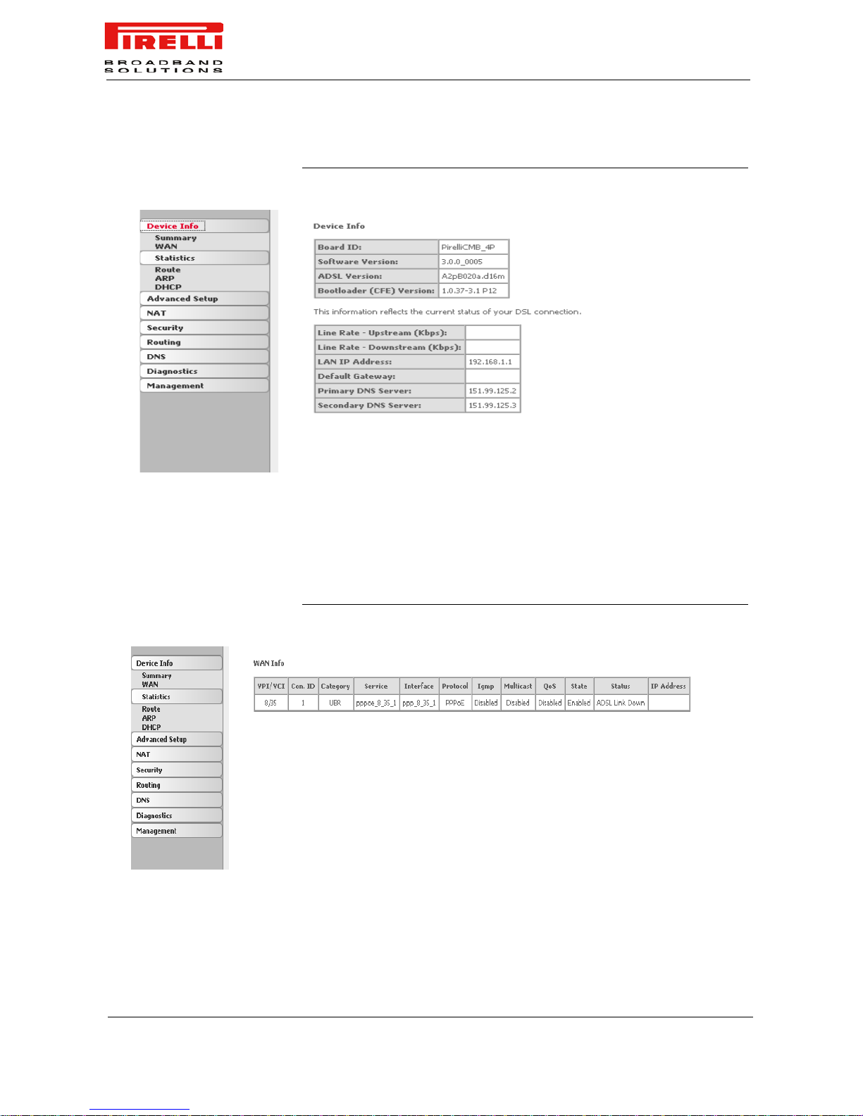
SUMMARY The Summary (see Figure 1), accessible through Device Info >>
Summary item selection, is a read-only page and contains details of
the router such as Hardware, Firmware and Software information,
LAN IP address, the current status of your DSL connection etc.
Be aware that any configuration change could compromise your connectivity.
Page 36
DISCUS™ Router
(C) (2006) Pirelli Broadband Solutions S.p.A. All Rights Reserved. Proprietary Use Pursuant to Cover Page Instructions.
30
OGU 930500118-A1
FIGURE 1. Summary Device Info Panel
WAN WAN Info section can be accessed by clicking on Device Info >> WAN. Since
a WAN connection has not been set up yet, there is no information to view.
After completing the configurations for a WAN connection, you can return to
this screen to view the information on you r WAN status.
FIGURE 2. WAN Info Panel
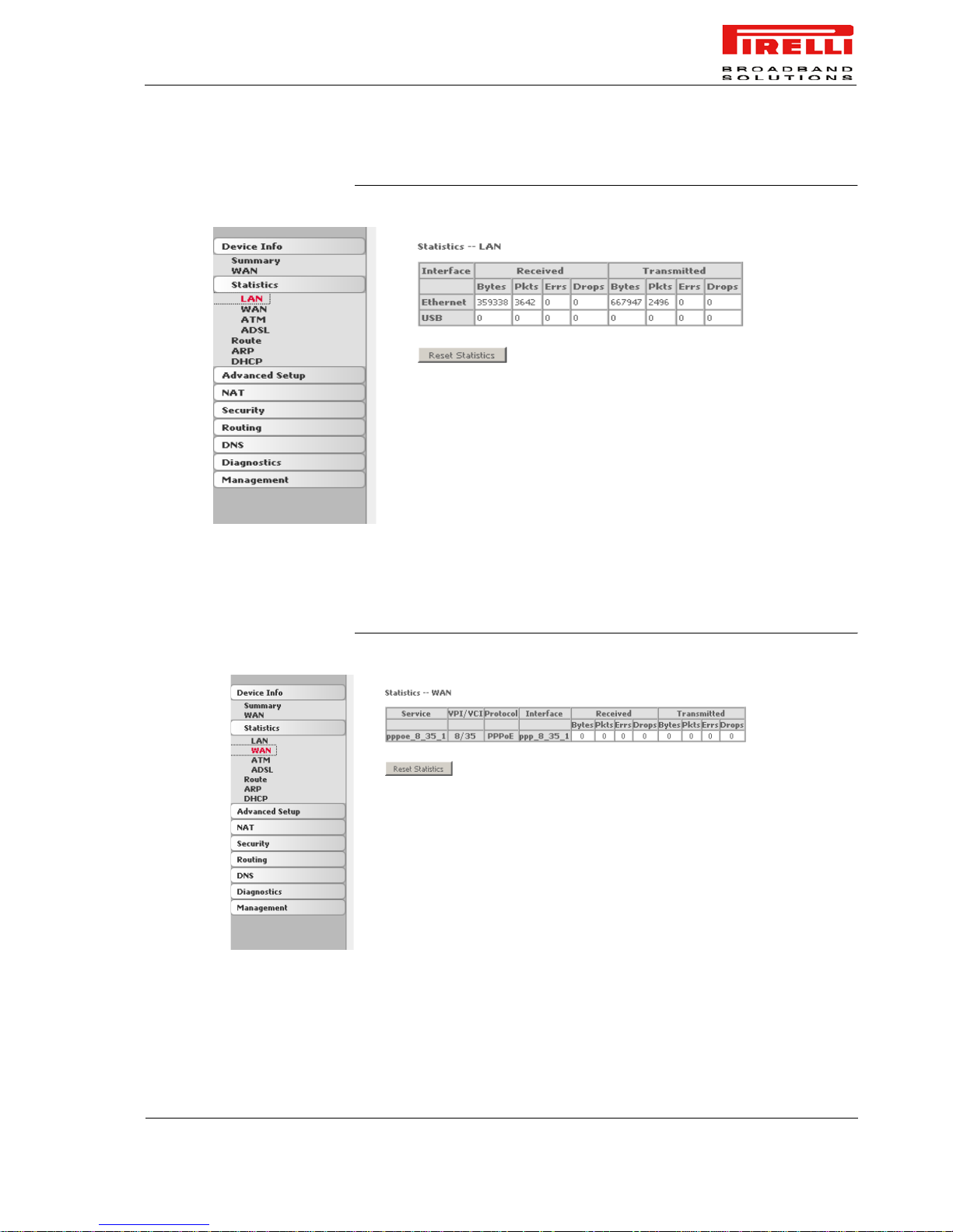
STATISTICS >> LAN Access the LAN statistics from the router by clic king on St atistic >> LAN. The
Reset Statistics button, will reset statistic counters.
Page 37
DISCUS™ Router
(C) (2006) Pirelli Broadband Solutions S.p.A. All Rights Reserved. Proprietary Use Pursuant to Cover Page Instructions.
31
OGU 930500118-A1
FIGURE 3. Statistics LAN Panel
STATISTICS >> WAN Access the WAN stat istics fr om the rou ter b y clic king on Statistic >> WAN. The
Reset Statistics button, will reset statistic counters.
FIGURE 4. Statistics WAN Panel
Page 38
DISCUS™ Router
(C) (2006) Pirelli Broadband Solutions S.p.A. All Rights Reserved. Proprietary Use Pursuant to Cover Page Instructions.
32
OGU 930500118-A1
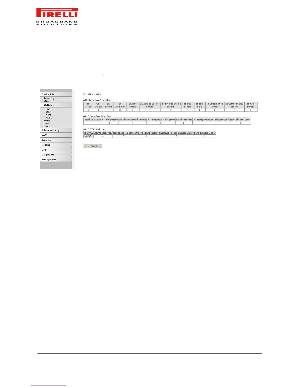
STATISTICS >> A T M Access the ATM statistics from the router by clicking on Statistic >> ATM. The
Reset Statistic button, will reset statistic ATM counters.
FIGURE 5. Statistics >> ATM Panel
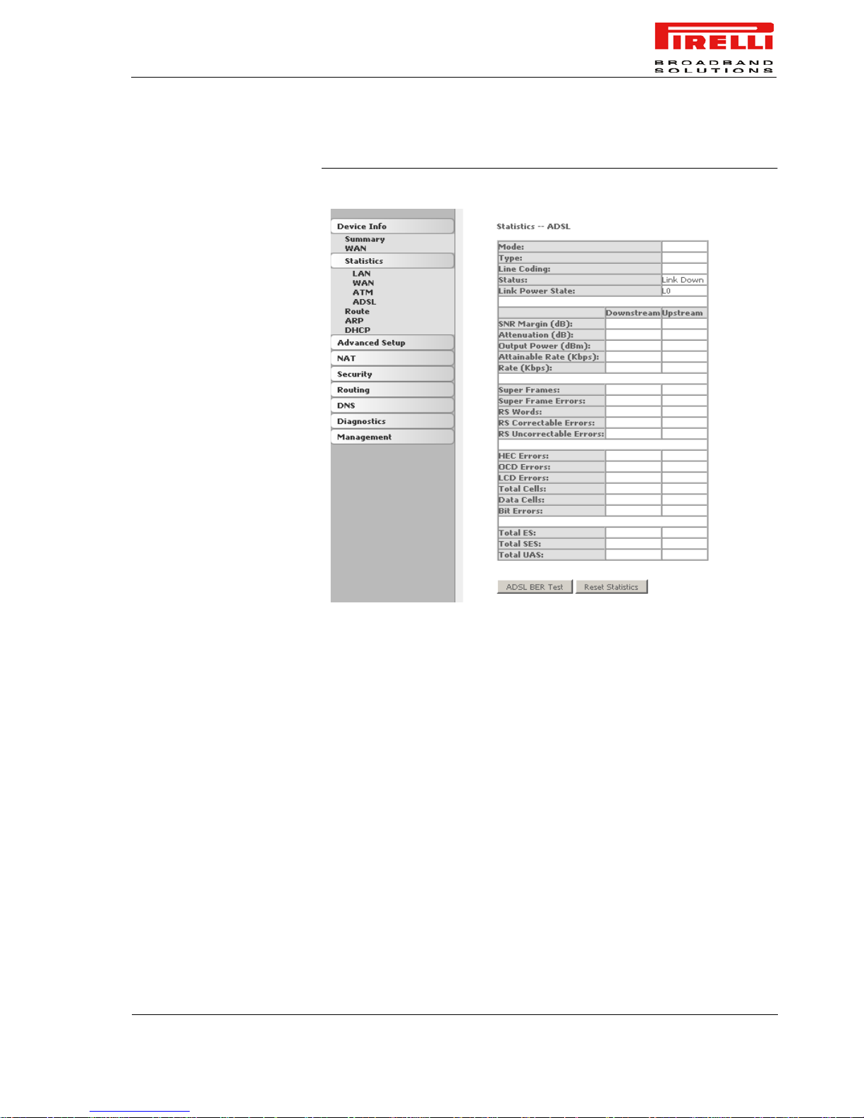
STATISTICS >> ADSL Access the DSL statistics from the router by clicking on Statistic >> ADSL.
Information contained in this screen is useful for troubleshooting and diagnostics of connection problems.
The Reset Statistics button, will reset statistic ADSL counters.
Page 39
DISCUS™ Router
(C) (2006) Pirelli Broadband Solutions S.p.A. All Rights Reserved. Proprietary Use Pursuant to Cover Page Instructions.
33
OGU 930500118-A1
FIGURE 6. Statistics >> ADSL Panel
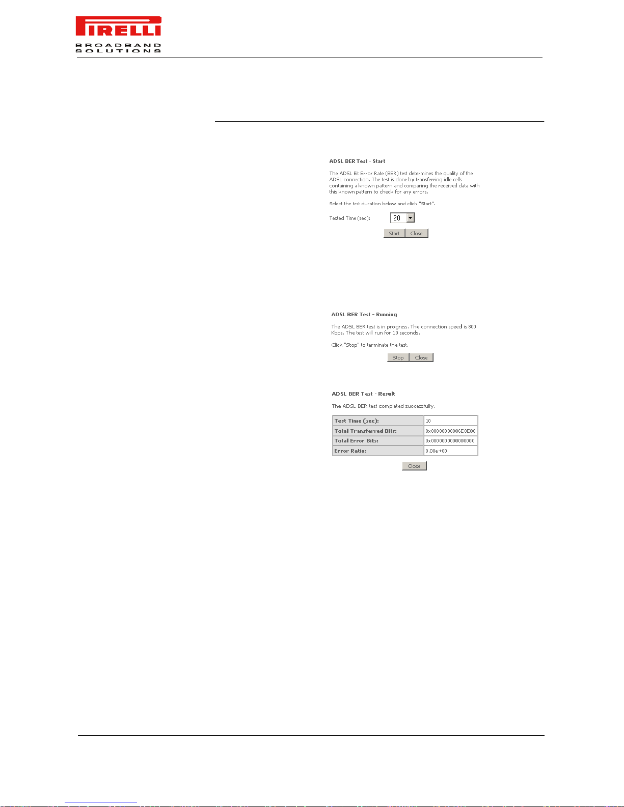
ADSL BER Test. A Bit Error Rate Test (BER Test) is a test that reflects the ratio
of error bits to the total number transmitted. If you click on the ADSL BER Test
button at the bottom of t he ADSL St atistics scr ee n, t he po p- up window shown in
Figure 7 will appear. Upon test duration choice (in seconds), and by pressing
the Start button, the test will start running. At its end a result page will be
shown. Do close this page by selecting the Close button.
Page 40
DISCUS™ Router
(C) (2006) Pirelli Broadband Solutions S.p.A. All Rights Reserved. Proprietary Use Pursuant to Cover Page Instructions.
34
OGU 930500118-A1
FIGURE 7. ADSL BER Test Panels
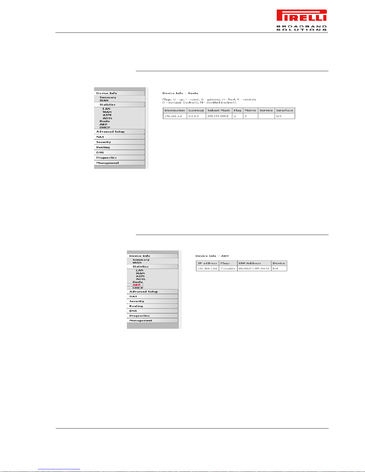
ROUTE Access the Routing Status report from the router by clicking on Route butt on
(see Figure 8).
Start phase
Run phase
Result phase
Page 41
DISCUS™ Router
(C) (2006) Pirelli Broadband Solutions S.p.A. All Rights Reserved. Proprietary Use Pursuant to Cover Page Instructions.
35
OGU 930500118-A1
FIGURE 8. Route Panel
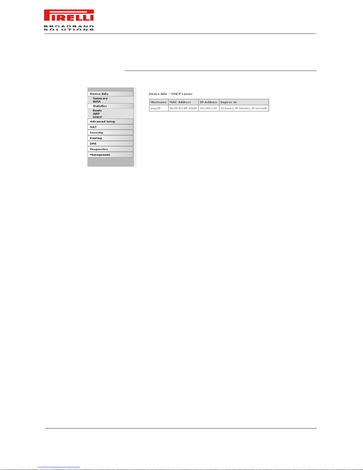
ARP Access the Routing Status repor t fr om the router by clicking on Device Info >>
ARP.
ARP (Address Resolution Protocol) maps the IP address to the physical
address, labeled HW Address (the MAC address) and helps to identify computers on the LAN.
FIGURE 9. ARP Panel
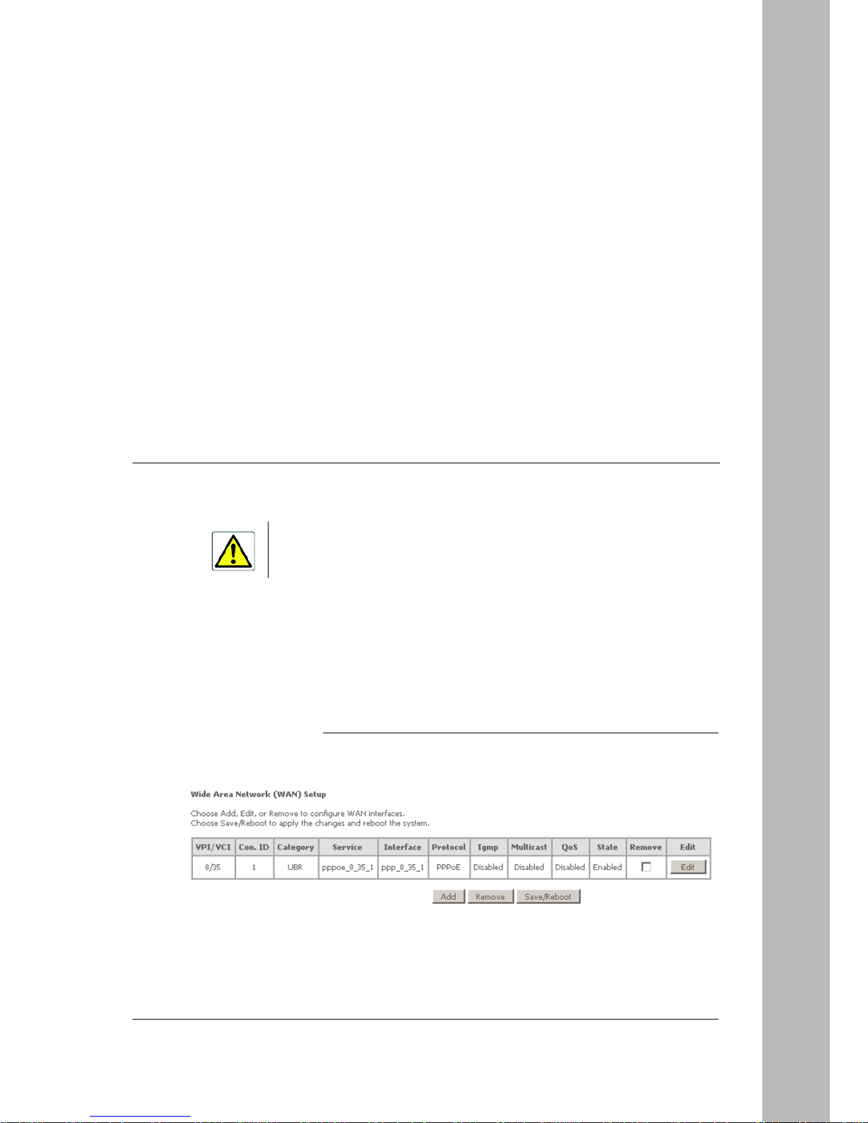
DHCP Access the DHCP leases from the router by clicking on Device Info >> DHCP.
It shows the computers, identified by the hostname and MAC address that have
acquired IP addresses by the DHCP server with the time that the lease for the
IP address is up.
Page 42
DISCUS™ Router
(C) (2006) Pirelli Broadband Solutions S.p.A. All Rights Reserved. Proprietary Use Pursuant to Cover Page Instructions.
36
OGU 930500118-A1
FIGURE 10. DHCP Panel
Page 43
(C) (2006) Pirelli Broadband Solutions S.p.A. All Rights Reserved. Proprietary Use Pursuant to Cover Page Instructions.
37OGU 930500118-A1
Advanced
Setup Section
This chapter will describe the Advanced Setup Section accessible
from the Home Page of the DISCUS™ Router. This section is only
accessible to a user with admin profile and is intended to collect most
of the advanced configuration functions.
WAN By selecting Advanced Setup >> WAN, the page, shown in
Figure 1, appears. It is used to configure the WAN settings as provided by your ISP.
FIGURE 1. WAN Setup Panel
Be aware that any configuration change could compromise your connectivity.
Page 44
DISCUS™ Router
(C) (2006) Pirelli Broadband Solutions S.p.A. All Rights Reserved. Proprietary Use Pursuant to Cover Page Instructions.
38
OGU 930500118-A1
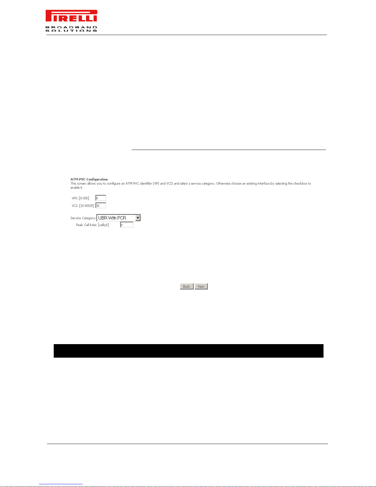
Click on the Add button if you want to add a new connection for the WAN
interface. The ATM PVC Configuration screen is shown in Figure 2. The ATM
PVC Configuration screen allows you to configure an ATM PVC identifier (VPI
and VCI) and select a service category.
Check the Remove check-box and select the Remove button to delete a
WAN configuration.
After an Add or Remove job, select the Save/Reboot button and the router will
reboot thus saving the changes.
FIGURE 2. Adding a WAN interface - Step 1
By clicking on the Add button, this screen allows you to configure an ATM
PVC identifier (VPI and VCI) and select a service category. Find out the va lues
listed in Table 1 from your ISP before you change them.
TABLE 1. ATM PVC Configuration parameters
Parameter Value Description
VPI 0-255 Virtual Path Identifier
VCI 32-65535 Virtual Channel Identifier
Page 45

DISCUS™ Router
(C) (2006) Pirelli Broadband Solutions S.p.A. All Rights Reserved. Proprietary Use Pursuant to Cover Page Instructions.
39
OGU 930500118-A1
Service Category UBR without PCR
UBR with PCR
CBR
Non Realtime VBR
Realtime VBR
- UBR Without PCR (Unspecified Bit Rate without Peak
Cell Rate). UBR service is suitable for applications that
can tolerate variable delays and some cell losses. Applications suitable for UBR service include text/data/image
transfer, messaging, distribution, and retrieval and also for
remote terminal applications such as telecommuting.
- UBR With PCR (Unspecified Bit Rate with Peak Cell
Rate)
- CBR (Constant Bit Rate) used by applications that
require a fixed data rate that is continuously available during the connection time. It is commonly used for uncompressed audio and video information such as
videoconferencing, interactive audio (telephony), audio /
video distribution (e.g. television, distance learning, and
pay-per-view), and audio / video retrieval (e.g. video-ondemand and audio library).
- Non Realtime VBR (Non-Real-time Variable Bit Rate)
can be used for data transfers that have critical responsetime requirements such as airline reservations, banking
transactions, and process monitoring.
- Realtime VBR (Real-time Variable Bit Rate) used by
time-sensitive applications such as real-time video. RtVBR service allows the network more flexibility than CBR.
Enable Quality of service true/false Enabling packet level QoS for a PVC improves perfor-
mance for selected classes of applications.
QoS cannot be set for CBR and Realtime VBR. QoS con-
sumes system resources; therefore the number of PVCs
will be reduced. Use Advanced Setup/Quality of Service
to assign priorities for the applications.
Peak Cell Rate [cells/sec] 1-255000 Can be set for all Service Categories with the exception of
“UBR without PCR“ Service Category
Sustainable Cell Rate [cells/s] Can be set only for Realtime and Non Realtime VBR.
Sustainble Cell Rate must be lower than Peak Cell Rate.
Maximum Burst Size: [cells] 1-1000000 Can be set only for Realtime and Non Realtime VBR.
Parameter Value Description
Page 46
DISCUS™ Router
(C) (2006) Pirelli Broadband Solutions S.p.A. All Rights Reserved. Proprietary Use Pursuant to Cover Page Instructions.
40
OGU 930500118-A1
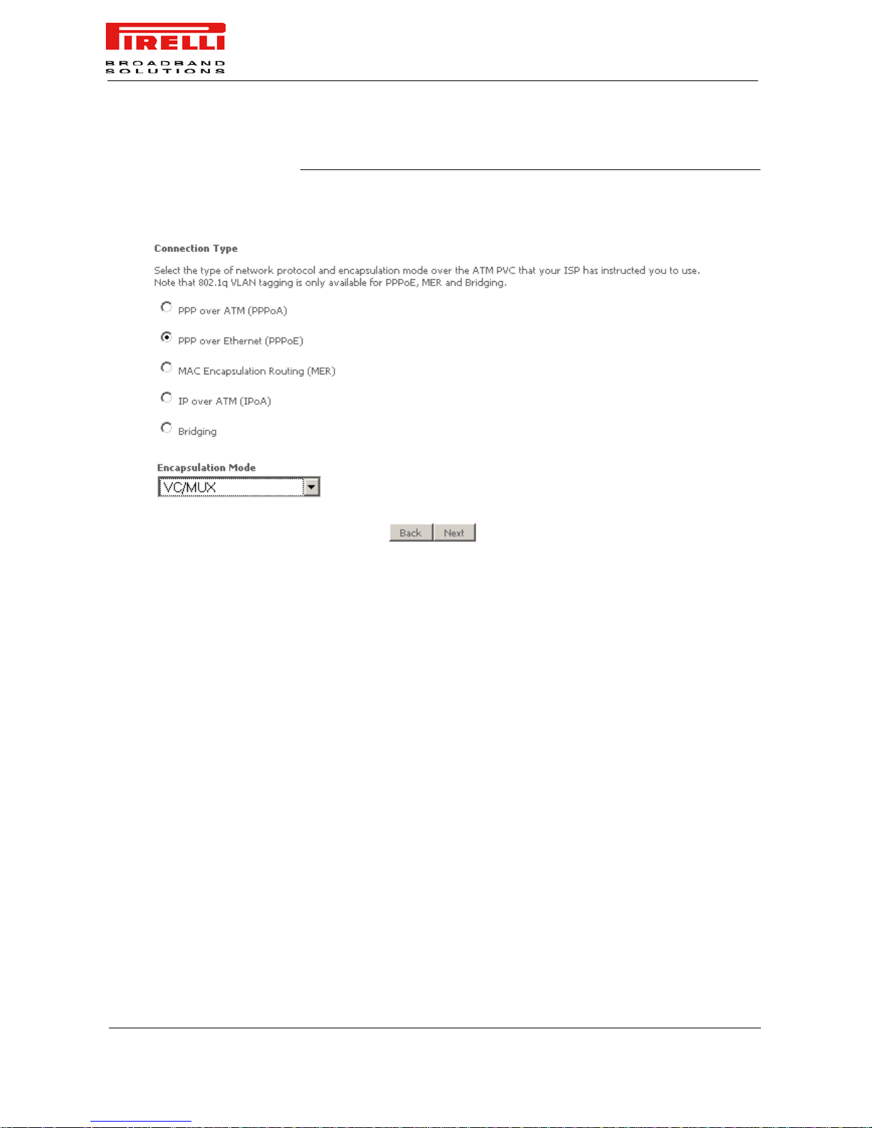
FIGURE 3. Adding a WAN interface - Step 2
Select the type of network protocol and encapsulation mode over the ATM PVC
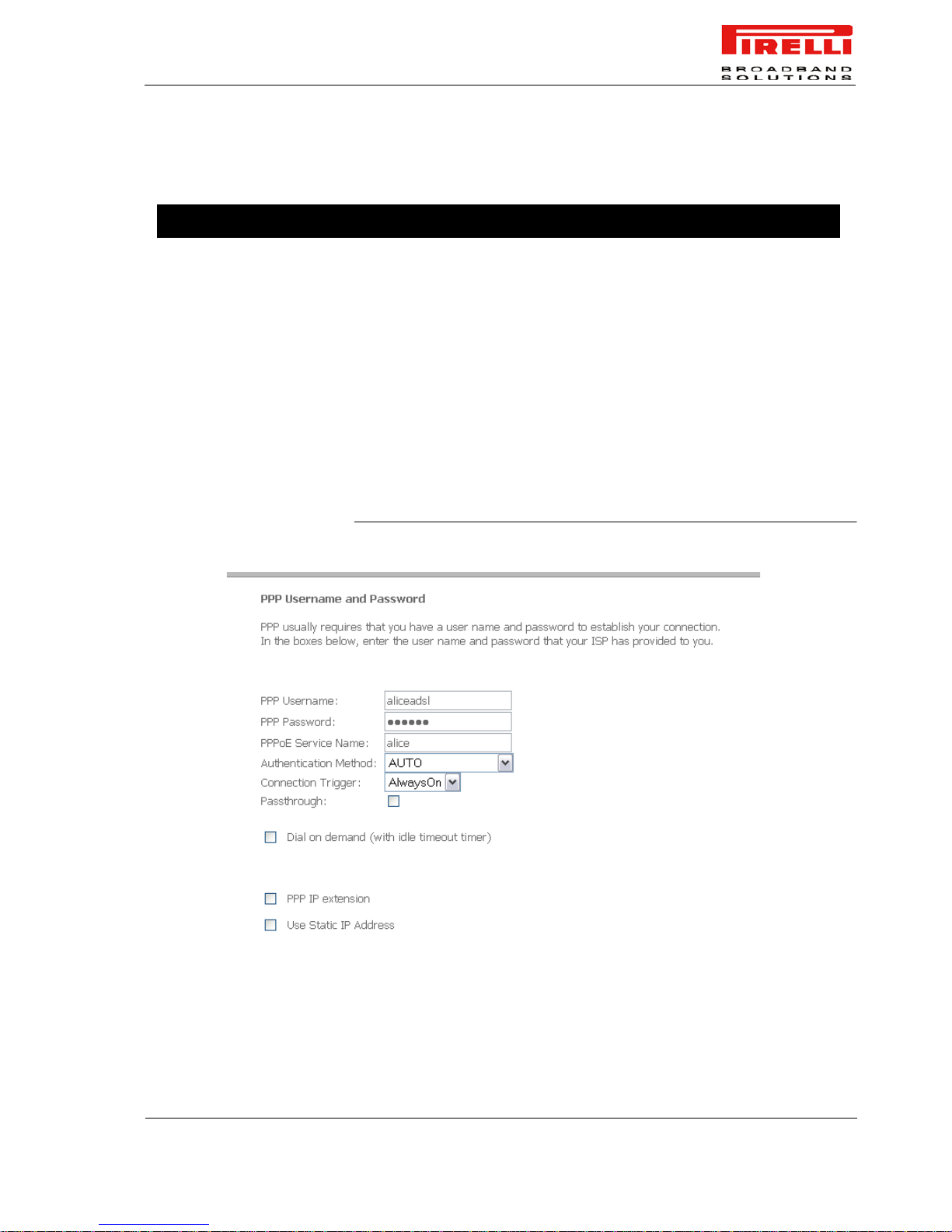
that your ISP has instructed you to use. Since this example uses a PPPoE con-
nection, the next screen (Figure 4) requires you to enter a PPP username and
password. After filling in the page and making any selections your ISP has
instructed you to , click on Next button to continue.
Page 47
DISCUS™ Router
(C) (2006) Pirelli Broadband Solutions S.p.A. All Rights Reserved. Proprietary Use Pursuant to Cover Page Instructions.
41
OGU 930500118-A1
TABLE 2. Connection Type Configuration Parameters
FIGURE 4. Adding a WAN interface - Step 3 (PPPoE case)
Parameter Value Description
Connection Type PPP over ATM (pppoA)
PPP over Ethernet (pppoE)
MAC Encapsulation Routing
(MER)
IP over ATM (IPoA)
Bridging
Encapsulation Mode VC/MUX
LLC/ENCAPSULATION
LLC/SNAP-BRIDGING
LLC/SNAP-ROUTING
- VC/MUX encapsulation is available to all connection
types
- LLC/ENCAPSULATION is available to PPPoA connection type
- LLC/SNAP-BRIDGING is available to PPPoE, MER and
Bridging connection types
- LLC/SNAP-ROUTING is available to IPoA connection
type
Page 48
DISCUS™ Router
(C) (2006) Pirelli Broadband Solutions S.p.A. All Rights Reserved. Proprietary Use Pursuant to Cover Page Instructions.
42
OGU 930500118-A1
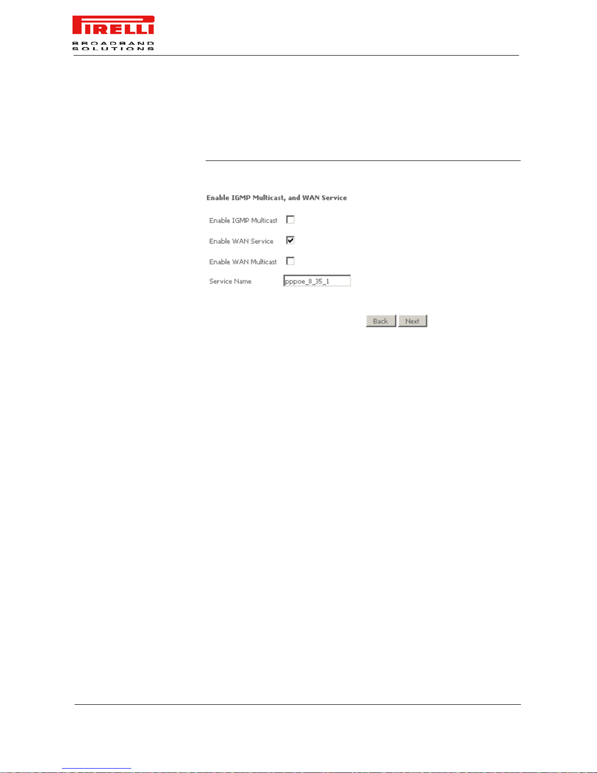
The next screen (Figure 5) allows you to configure NAT either by enabling or
disabling it. Other services include IGMP multicast and WAN se rvice. After making your selections, click on Next button to go on to the next page.
FIGURE 5. Adding a WAN interface - Step 4
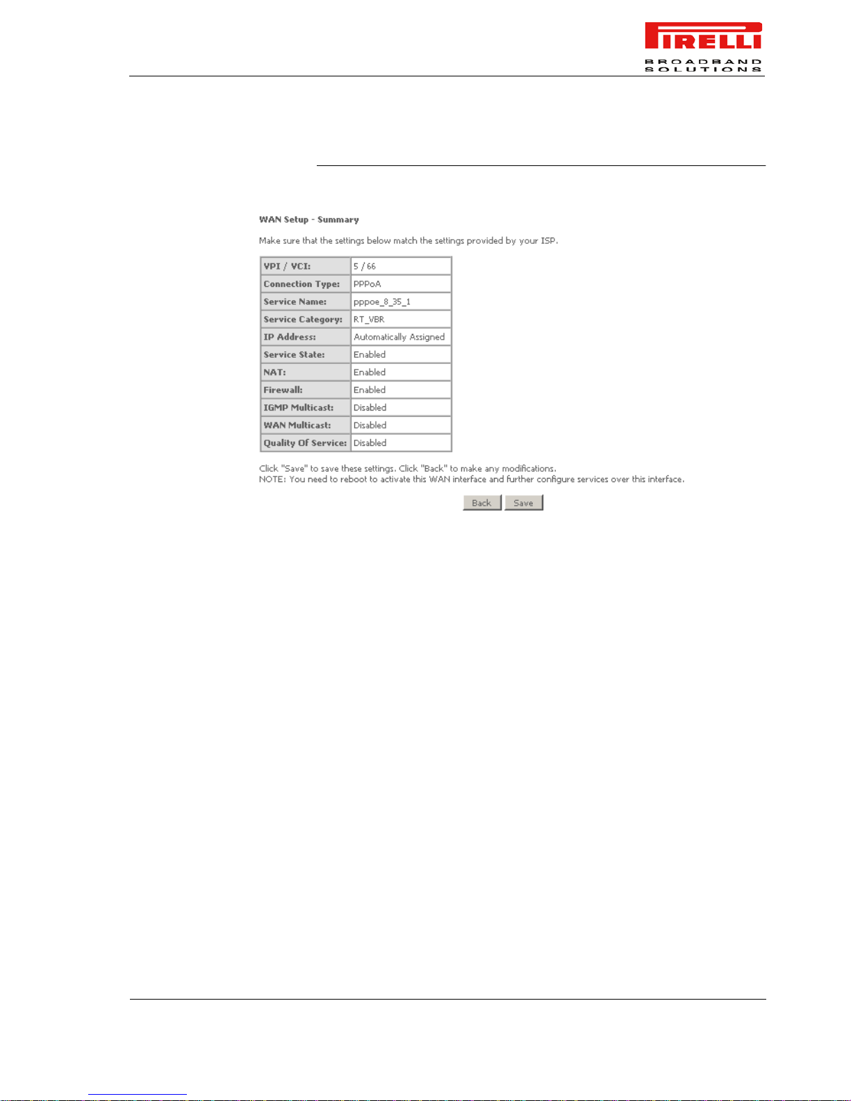
When the settings are complete, the screen in Figure 6 appears showing a
WAN Setup – Summary screen to display the WAN configurations. Click on
Save button to save the settings.
Page 49
DISCUS™ Router
(C) (2006) Pirelli Broadband Solutions S.p.A. All Rights Reserved. Proprietary Use Pursuant to Cover Page Instructions.
43
OGU 930500118-A1
FIGURE 6. Adding a WAN interface - Step 5: Summary
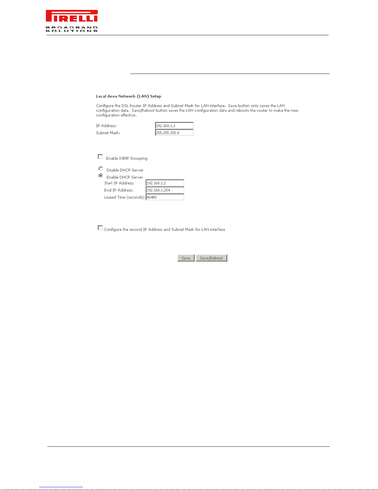
LAN You can configure the DSL Router IP address and Subnet Mask for the LAN
interface to correspond to your LAN’s IP Subnet. If you want the DHCP server
to automatically assign IP addresses, then enable the DHCP server and enter
the range of IP addresses that the DHCP server can assign to your computers.
Disable the DHCP server if you prefer to manually assign IP addresses. Click
on Next button to continue.
The Save button only saves the LAN configuration data, but does not apply the
configurations. Select the Save/Reboot button to save the LAN configuration
data and reboot the router applying the new configurations.
Page 50
DISCUS™ Router
(C) (2006) Pirelli Broadband Solutions S.p.A. All Rights Reserved. Proprietary Use Pursuant to Cover Page Instructions.
44
OGU 930500118-A1
FIGURE 7. LAN Panel
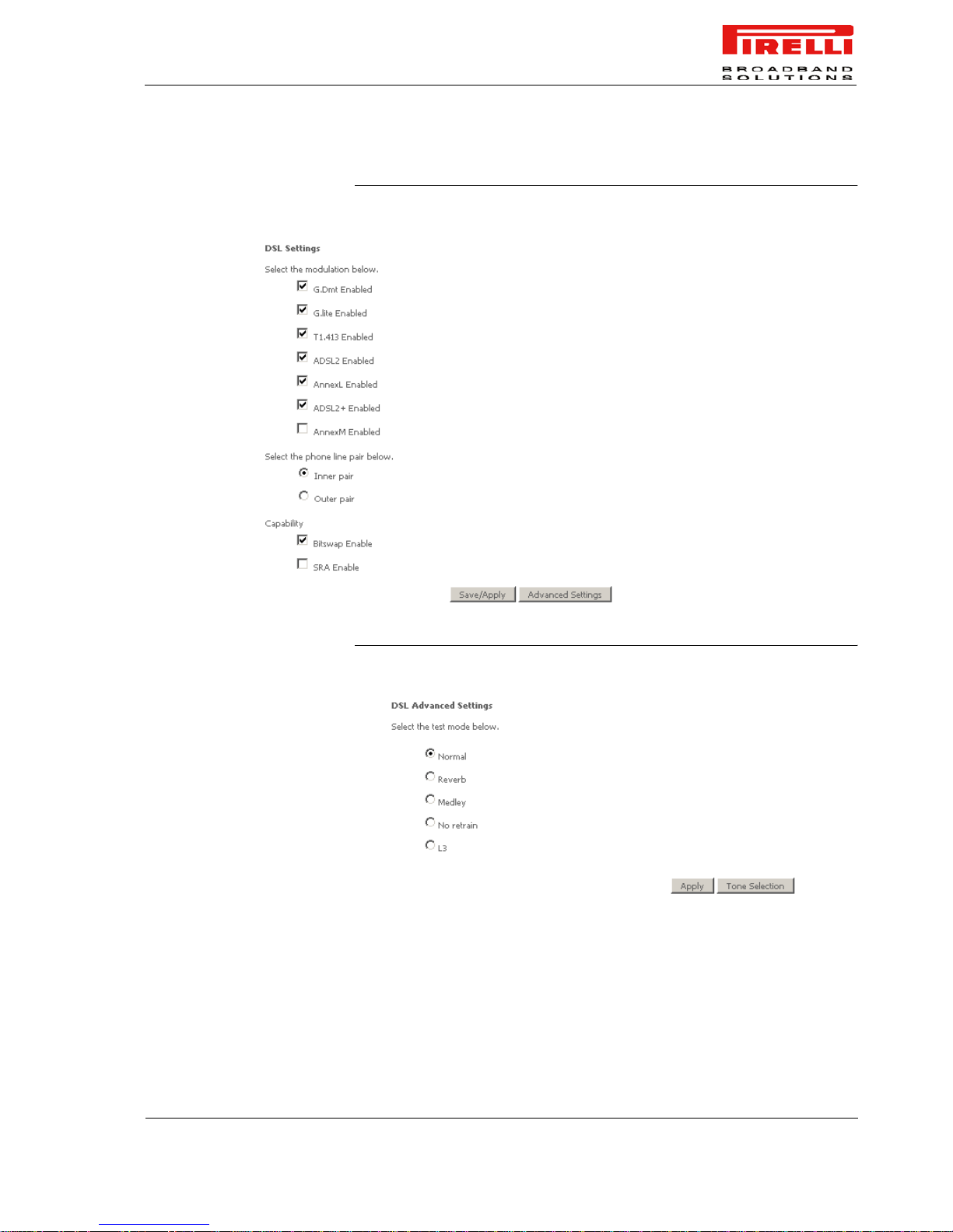
DSL The DSL settings screen contains three sections: mo dulation, phone line, and
capability that should be specified by your ISP.
Consult with your ISP to select the correct settings for each. Then click on
Save/Apply if you are finished or click on Advanced Settings button if you
want to configure more advanced settings.
Page 51
DISCUS™ Router
(C) (2006) Pirelli Broadband Solutions S.p.A. All Rights Reserved. Proprietary Use Pursuant to Cover Page Instructions.
45
OGU 930500118-A1
FIGURE 8. DSL Settings Panel
FIGURE 9. DSL Advanced Settings Panel
The test mode can be selected from the DSL Adva nced Settings screen. Test
modes include—normal, reverb, medley, no retrain, and L3.
Page 52
DISCUS™ Router
(C) (2006) Pirelli Broadband Solutions S.p.A. All Rights Reserved. Proprietary Use Pursuant to Cover Page Instructions.
46
OGU 930500118-A1
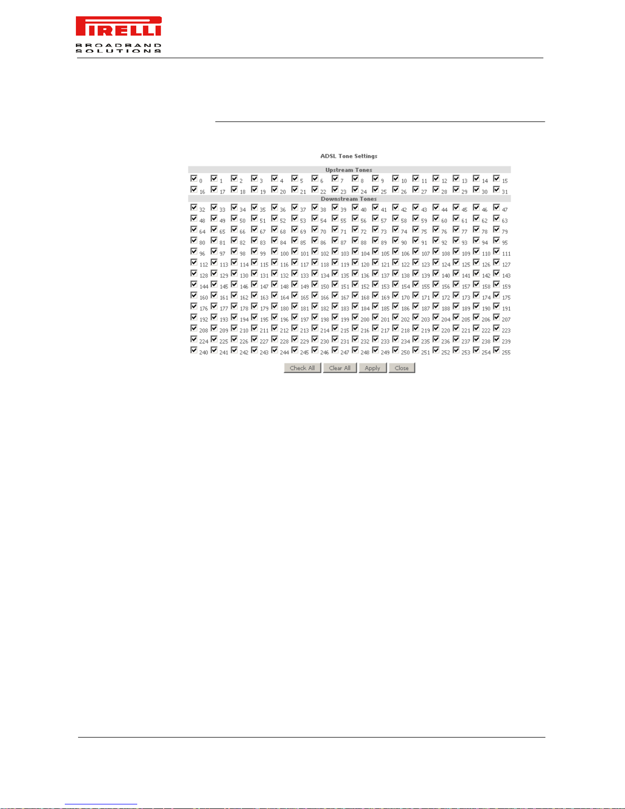
FIGURE 10. DSL Advanced Settings - Tone Selection Panel
The frequency band of ADSL is split up into 256 separate tones, each spaced
4.3125 kHz apar t. With each tone carrying separate data, the technique oper-
ates as if 256 separate modems we re running in par allel. The t one r ange is fro m
0 to 31 for upstream and from 32 to 255 for downstream. Do not change these
settings unless so directed by your ISP.
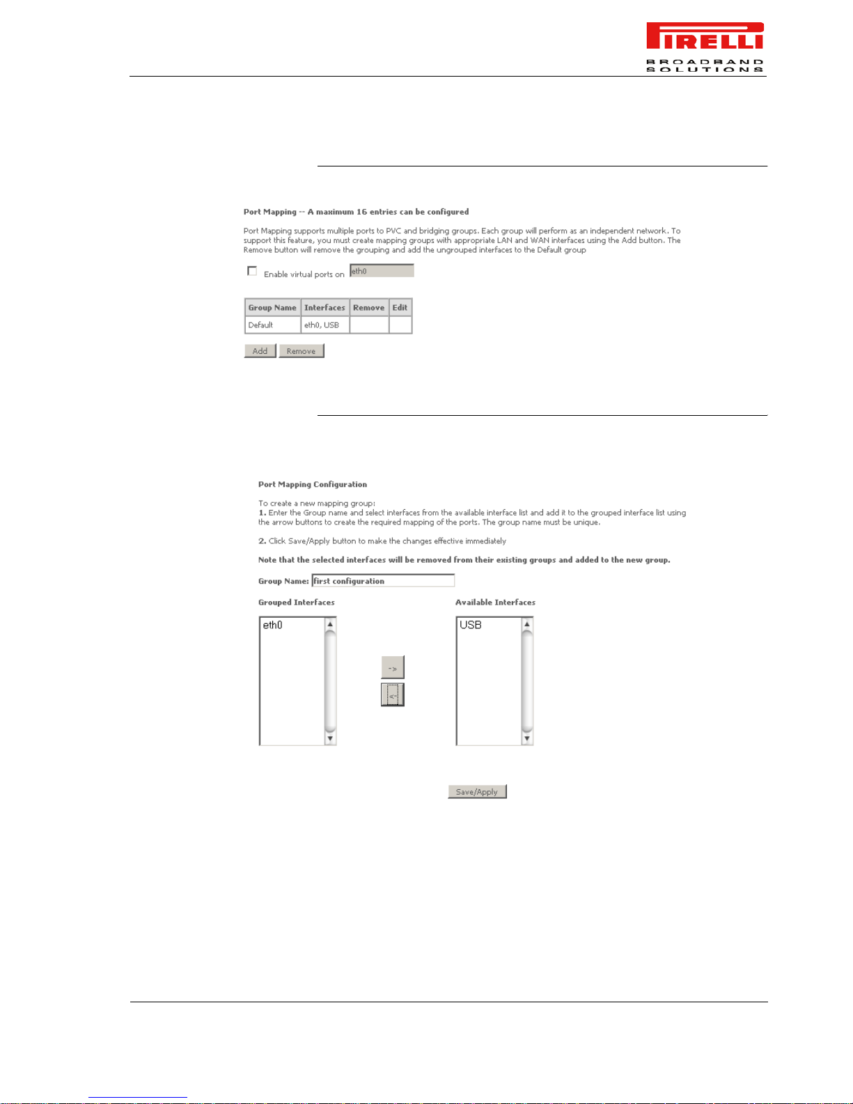
PORT MAPPING Port mapping is a feature that allows you to open ports to allow certain Internet
applications on the WAN side to pass through the firewall and enter your LAN.
To use this feature, mapping groups need to be created by clicking on the Add
button.
Port Mapping supports multiple ports to PVC and bridging groups. Each group
will perform as an independent network. The Remove button will remove the
grouping and add the ungrouped interfaces to the Default group. Only the
default group has IP interface.
Page 53
DISCUS™ Router
(C) (2006) Pirelli Broadband Solutions S.p.A. All Rights Reserved. Proprietary Use Pursuant to Cover Page Instructions.
47
OGU 930500118-A1
FIGURE 11. Port Mapping Panel
FIGURE 12. Port Mapping - Add Panel
After clicking the Add button (see Figure 12), the below configuration screen
appears, allowing you to enter the groups and the interfaces they are associated with.
Page 54

DISCUS™ Router
(C) (2006) Pirelli Broadband Solutions S.p.A. All Rights Reserved. Proprietary Use Pursuant to Cover Page Instructions.
48
OGU 930500118-A1
Page 55
(C) (2006) Pirelli Broadband Solutions S.p.A. All Rights Reserved. Proprietary Use Pursuant to Cover Page Instructions.
49OGU 930500118-A1
NAT Section
This chapter will describe the NAT Section accessible from the
Home Page of the DISCUS™ Router. This section is only accessible
to a user with admin profile and is intended to configure NAT functionalities.
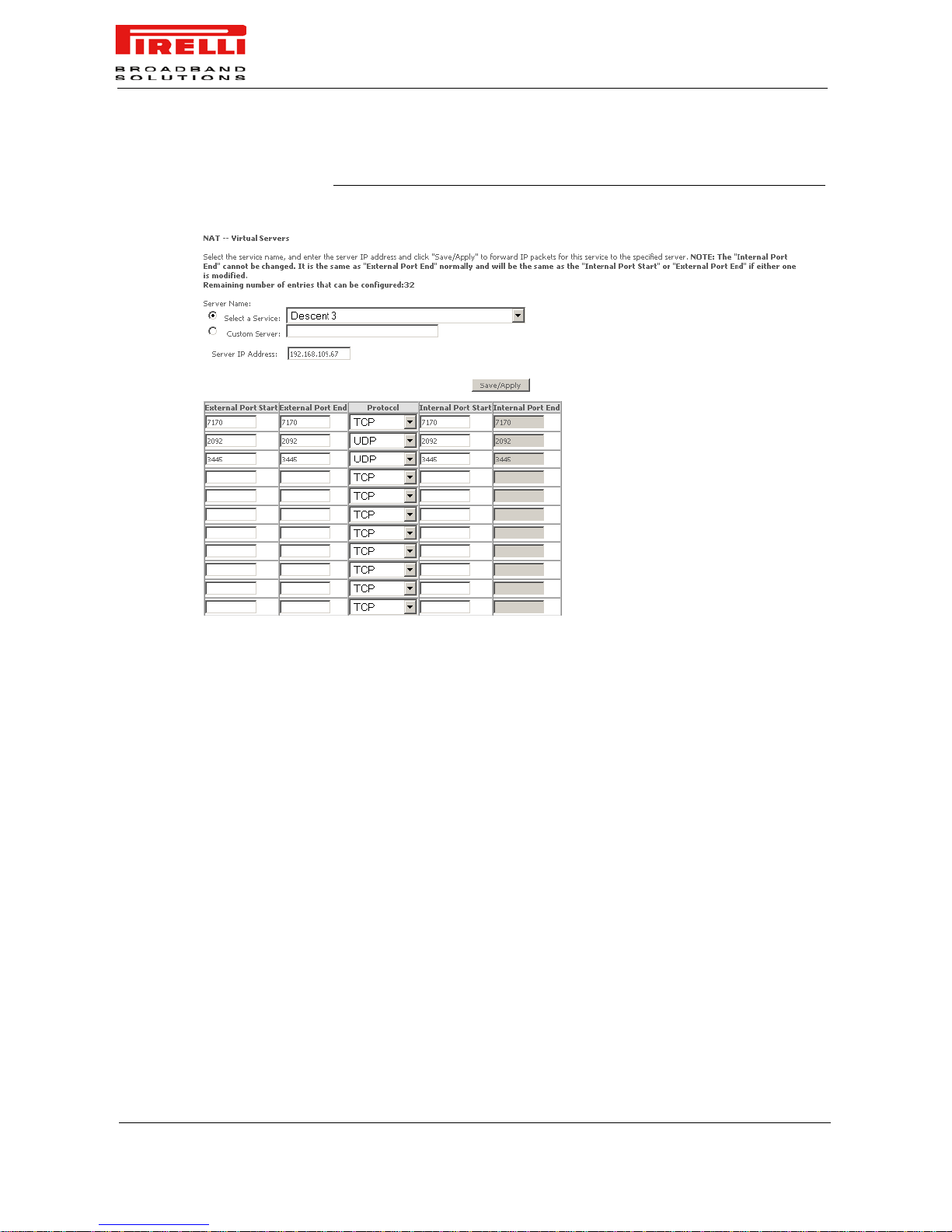
VIRTUAL SERVERS If you enable NAT (Network Address Translation), you can configure
the Virtual Server, Port Triggering and DMZ Host.
Virtual Server allows you to direct incoming traffic from WAN side
(identified by Protocol and External port) to the Internal server with
private IP address on the LAN side. The Internal port is required only
if the external port needs to be converted to a different port number
used by the server on the LAN side. A maximum of 32 entries can be
configured.
To add additional virtual servers, click on the Add button. If you
need to remove any of the server names, select the check box and
click on the Remove button.
Be aware that any configuration change could compromise your connectivity.
Page 56
DISCUS™ Router
(C) (2006) Pirelli Broadband Solutions S.p.A. All Rights Reserved. Proprietary Use Pursuant to Cover Page Instructions.
50
OGU 930500118-A1
FIGURE 1. NAT - Virtual Servers Setup Panel
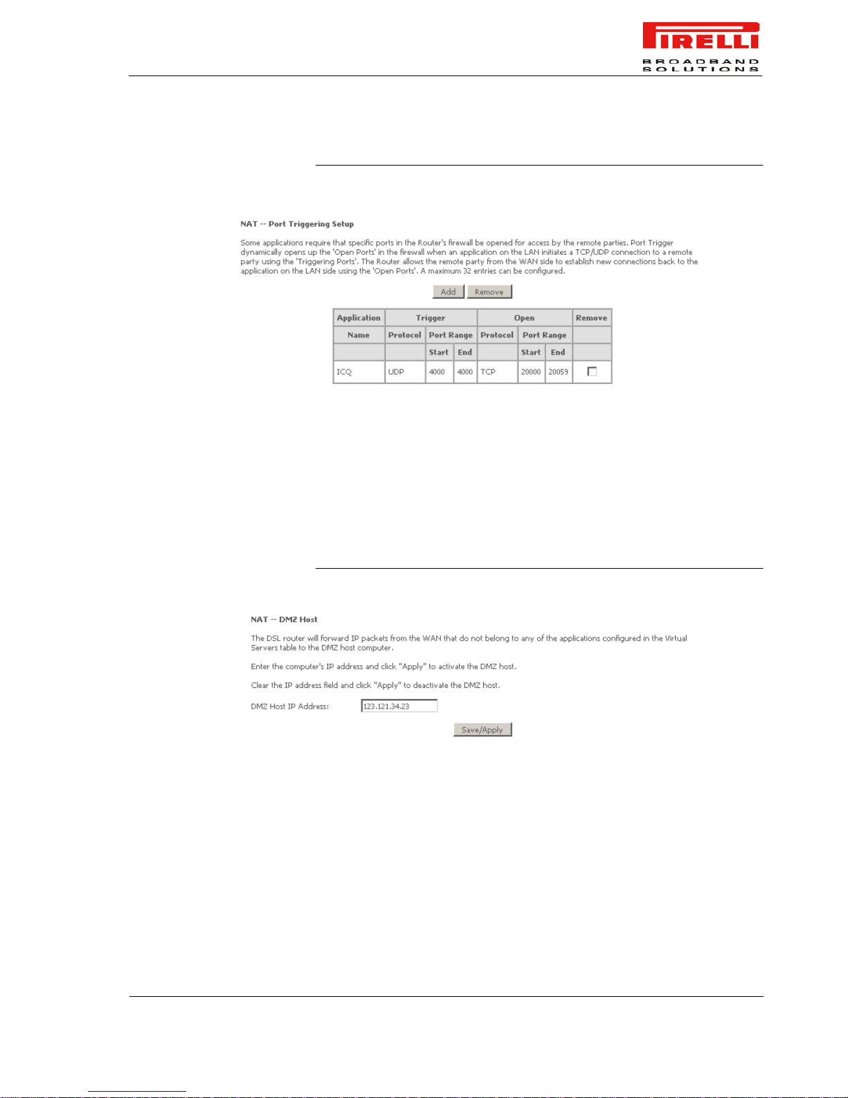
PORT TRIGGERING Some applications require that specific ports in the Router's firewall be opened
for access by the remote parties. Port Trigger dynamically opens up the 'Open
Ports' in the firewall when an application on the LAN initiates a TCP/UDP connection to a remote party using the 'Triggering Ports'. The Router allows the
remote party from the WAN side to establish new connections back to the
application on the LAN side using the 'Open Ports'. A maximum of 32 entries
can be configured.
Page 57
DISCUS™ Router
(C) (2006) Pirelli Broadband Solutions S.p.A. All Rights Reserved. Proprietary Use Pursuant to Cover Page Instructions.
51
OGU 930500118-A1
FIGURE 2. NAT - Port Triggering Setup Panel
DMZ HOST The DSL router will forward IP packets from the WAN that do not belong to any
of the applications configured in the Virtual Servers table to the DMZ host computer.
Enter the IP address and click on Save/Apply button.
FIGURE 3. NAT - DMZ Host Panel
Page 58

DISCUS™ Router
(C) (2006) Pirelli Broadband Solutions S.p.A. All Rights Reserved. Proprietary Use Pursuant to Cover Page Instructions.
52
OGU 930500118-A1
Page 59
(C) (2006) Pirelli Broadband Solutions S.p.A. All Rights Reserved. Proprietary Use Pursuant to Cover Page Instructions.
53OGU 930500118-A1
Security
Section
This chapter will describe the Security Section accessible from the
Home Page of the DISCUS™ Router. This section is only accessible
to a user with admin profile and is intended to collect most of the
security configuration functions.
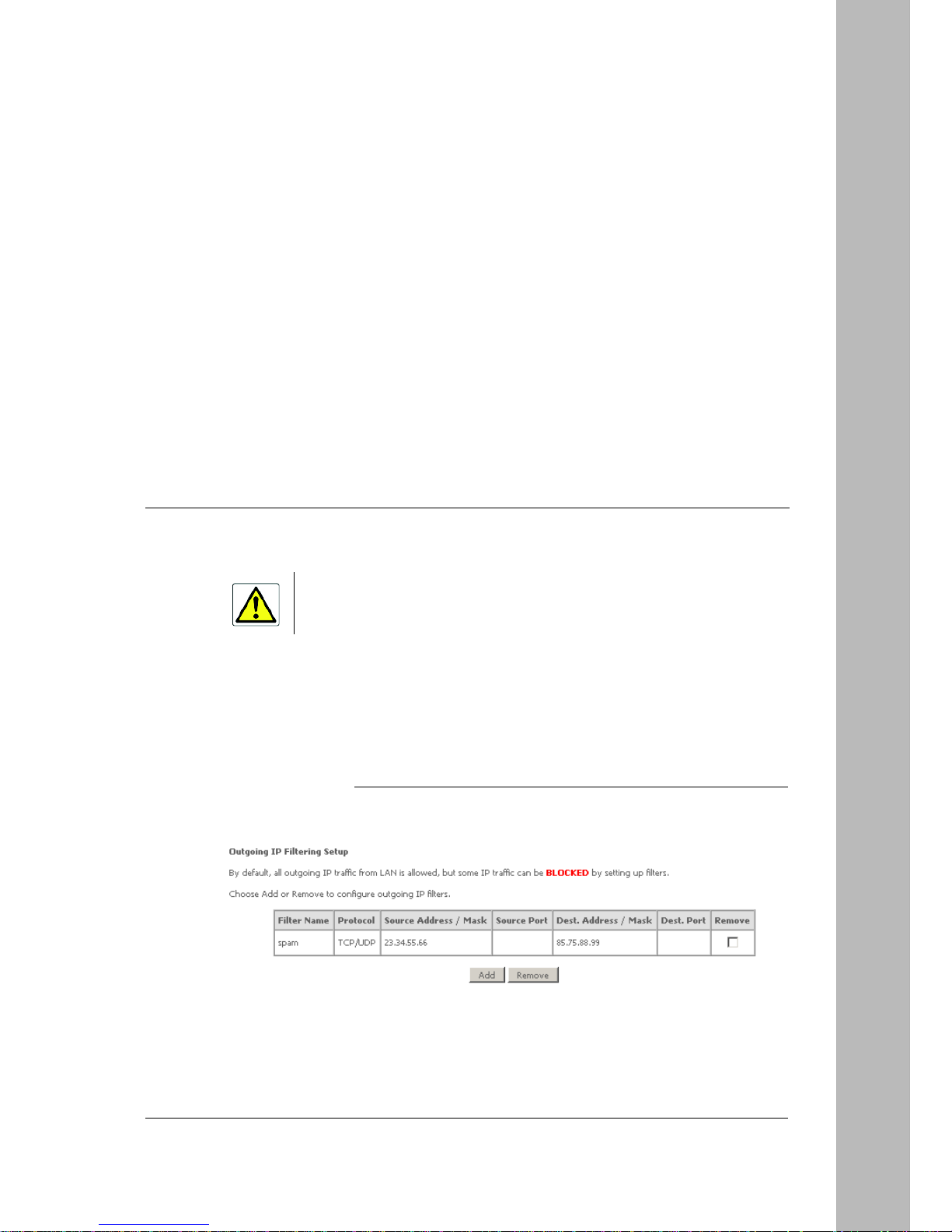
IP FILTERING >> OUTGOING The outgoing filter will block the LAN traffic from entering the WAN
side.
FIGURE 1. Outgoing IP Filtering Setup Panel
Be aware that any configuration change could compromise your connectivity.
Page 60
DISCUS™ Router
(C) (2006) Pirelli Broadband Solutions S.p.A. All Rights Reserved. Proprietary Use Pursuant to Cover Page Instructions.
54
OGU 930500118-A1
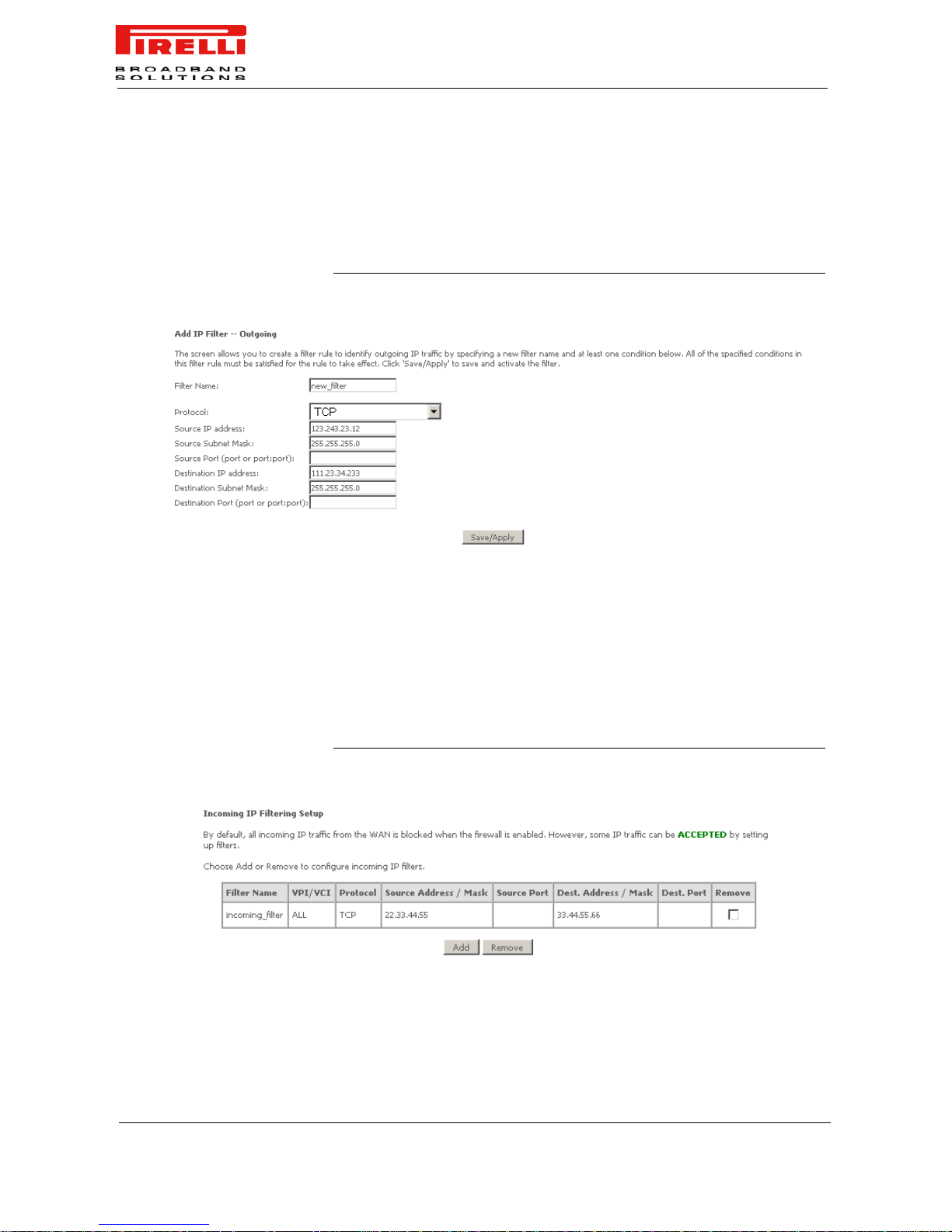
Figure 1 lists the IP filters that were added. Click on the Add button to create
new filters. Input the filter name, source information (from the LAN side), and
destination information (from the WAN side). Then click on Save/Apply (see
Figure 2).
FIGURE 2. Outgoing IP Filtering Setup - Add Panel
IP FILTERING >> INCOMING By default, all incoming IP traffic from the WAN is blocked when the firewall is
enabled. However, some IP traffic can be ACCEPTED by setting up filters.
Click on the Add button to add incoming filter settings.
Enter a filter name, information about the source address (from the WAN
side), and information about the destination ad dress (to th e LAN side). Select
the protocol and WAN interface, then click on Save/Apply to add the setting
FIGURE 3. IP Filtering - Incoming Panel
Page 61
(C) (2006) Pirelli Broadband Solutions S.p.A. All Rights Reserved. Proprietary Use Pursuant to Cover Page Instructions.
55OGU 930500118-A1
Routing Section
This chapter will describe the Routing Section accessible from the
Home Page of the DISCUS™ Router. This section is only accessible
to a user with admin profile and is intended to collect most of the
Routing configuration functions.
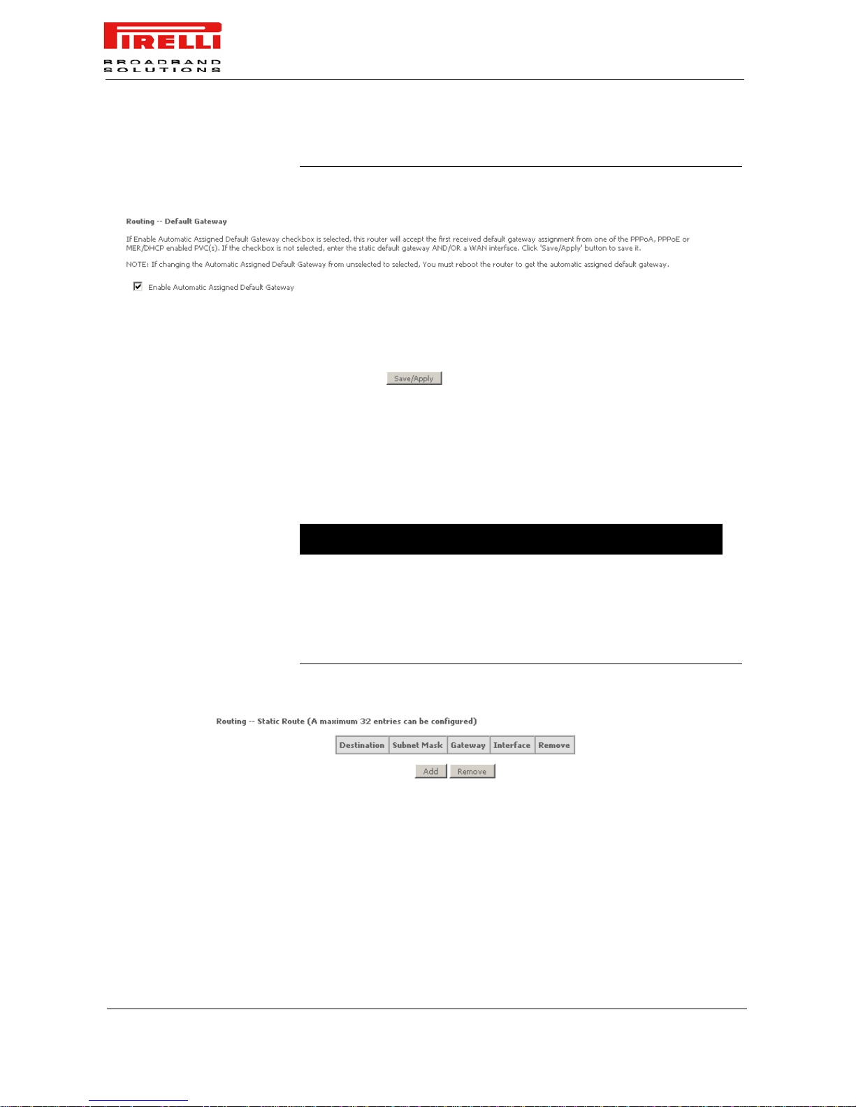
DEFAULT GATEWAY If Enable Automatic Assigned Default Gateway checkbox is selected,
this router will accept the first received default gateway assignment
from one of the PPPoA, PPPoE or MER/DHCP enabled PVC(s). If
the checkbox is not selected, enter the static default gateway AND/
OR a WAN interface. Click Save/Apply button to save it.
Be aware that any configuration change could compromise your connectivity.
If changing the Automatic Assigned Default Gateway from unselected to selected, You must
reboot the router to get the automatic assigned default gateway.
Page 62
DISCUS™ Router
(C) (2006) Pirelli Broadband Solutions S.p.A. All Rights Reserved. Proprietary Use Pursuant to Cover Page Instructions.
56
OGU 930500118-A1
FIGURE 1. Default Gateway Panel
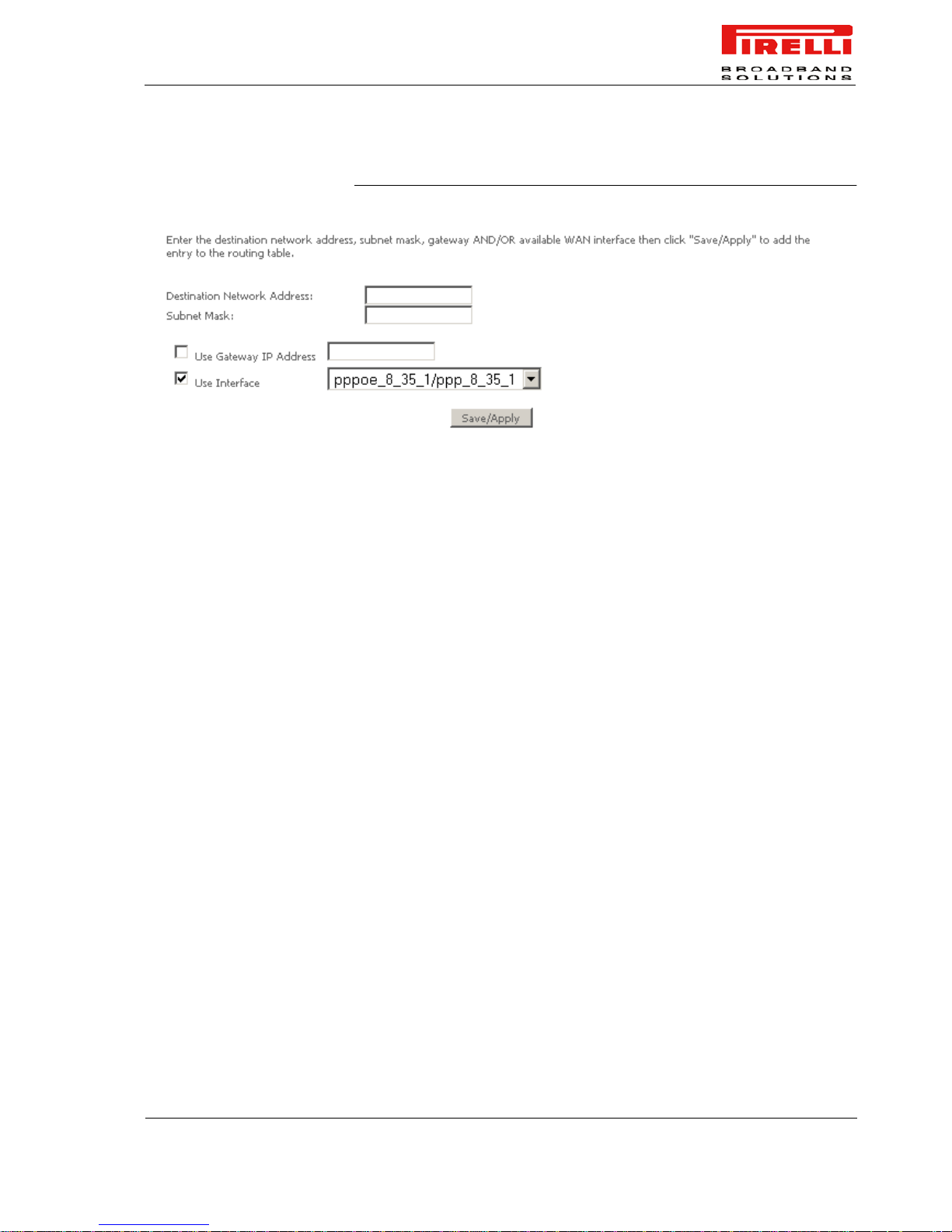
STATIC ROUTE The Static Route screen can be used to add a routing tab le (a maxim um of 32
entries can be configured). Click on Add button to add a static route and, at
the end of parameters’ configuration, press the Save/Apply button. The
Remove button, upon a route selection, will delete existing static routes.
TABLE 1. Static Route Parameters
FIGURE 2. Static Route Panel
Parameter Description Example
Destination Destination Network address 20.0.0.0
Subnet Mask Subnet mask 255.255.255.0
Gateway Gateway IP address
Interface Available WAN interfaces br0
Page 63
DISCUS™ Router
(C) (2006) Pirelli Broadband Solutions S.p.A. All Rights Reserved. Proprietary Use Pursuant to Cover Page Instructions.
57
OGU 930500118-A1
FIGURE 3. Add - Static Route Panel
Page 64

DISCUS™ Router
(C) (2006) Pirelli Broadband Solutions S.p.A. All Rights Reserved. Proprietary Use Pursuant to Cover Page Instructions.
58
OGU 930500118-A1
Page 65
(C) (2006) Pirelli Broadband Solutions S.p.A. All Rights Reserved. Proprietary Use Pursuant to Cover Page Instructions.
59OGU 930500118-A1
DNS Section
This chapter will describe the DNS Section accessible from the
Home Page of the DISCUS™ Router. This section is only accessible
to a user with admin profile and is intended to collect most of the
DNS configuration functions.
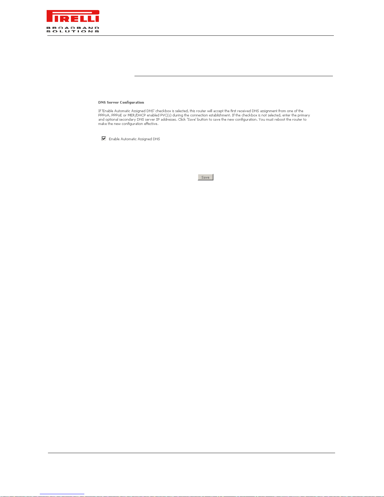
DNS SERVER Use the DNS Server screen to enable automatic assignment of a
DNS or to specify a primary and secondary DNS.
If Enable Automatic Assigned DNS checkbox is selected, this
router will accept the first received DNS assignment from one of the
PPPoA, PPPoE or MER/DHCP enabled PVC(s) during the connection establishment. If the checkbox is not selected, enter the primary
and optional secondary DNS server IP addresses. Click Save button
to save the new configuration. You must reboot the router to make
the new configuration effective.
Be aware that any configuration change could compromise your connectivity.
Page 66
DISCUS™ Router
(C) (2006) Pirelli Broadband Solutions S.p.A. All Rights Reserved. Proprietary Use Pursuant to Cover Page Instructions.
60
OGU 930500118-A1
FIGURE 1. DNS Server Panel
Page 67
(C) (2006) Pirelli Broadband Solutions S.p.A. All Rights Reserved. Proprietary Use Pursuant to Cover Page Instructions.
61OGU 930500118-A1
Diagnostics
Section
This chapter will describe the Diagnostics Section accessible from
the Home Page of the DISCUS™ Router.
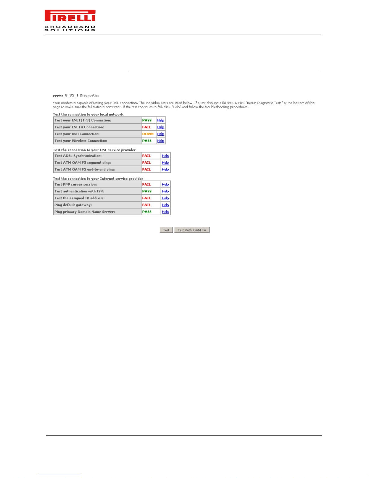
By selecting Diagnostics, the page, shown in Figure 1, is shown. By
means of this page it will be possible to run diagnostic tests to check
your DSL connection. The results will show test results of three connections:
1. Connection to your local network
2. Connection to your DSL service provider
3. Connection to your Internet service provider
There are two buttons at the bottom of the screen: Test and Test
with OAM F4, which will allow y ou to execute the test again, if neces-
sary.
Be aware that any configuration changes could compromise your connectivity.
Page 68
DISCUS™ Router
(C) (2006) Pirelli Broadband Solutions S.p.A. All Rights Reserved. Proprietary Use Pursuant to Cover Page Instructions.
62
OGU 930500118-A1
FIGURE 1. Diagnost ics Panel
Page 69
(C) (2006) Pirelli Broadband Solutions S.p.A. All Rights Reserved. Proprietary Use Pursuant to Cover Page Instructions.
63OGU 930500118-A1
Management
Section
This chapter will describe the Management Section accessible from
the Home Page of the DISCUS™ Router.
The Management section gives you access to cer tain setups for the
purpose of maintaining the system, including backing up the configurations, viewing system log, maintaining access control, updating
software, etc.
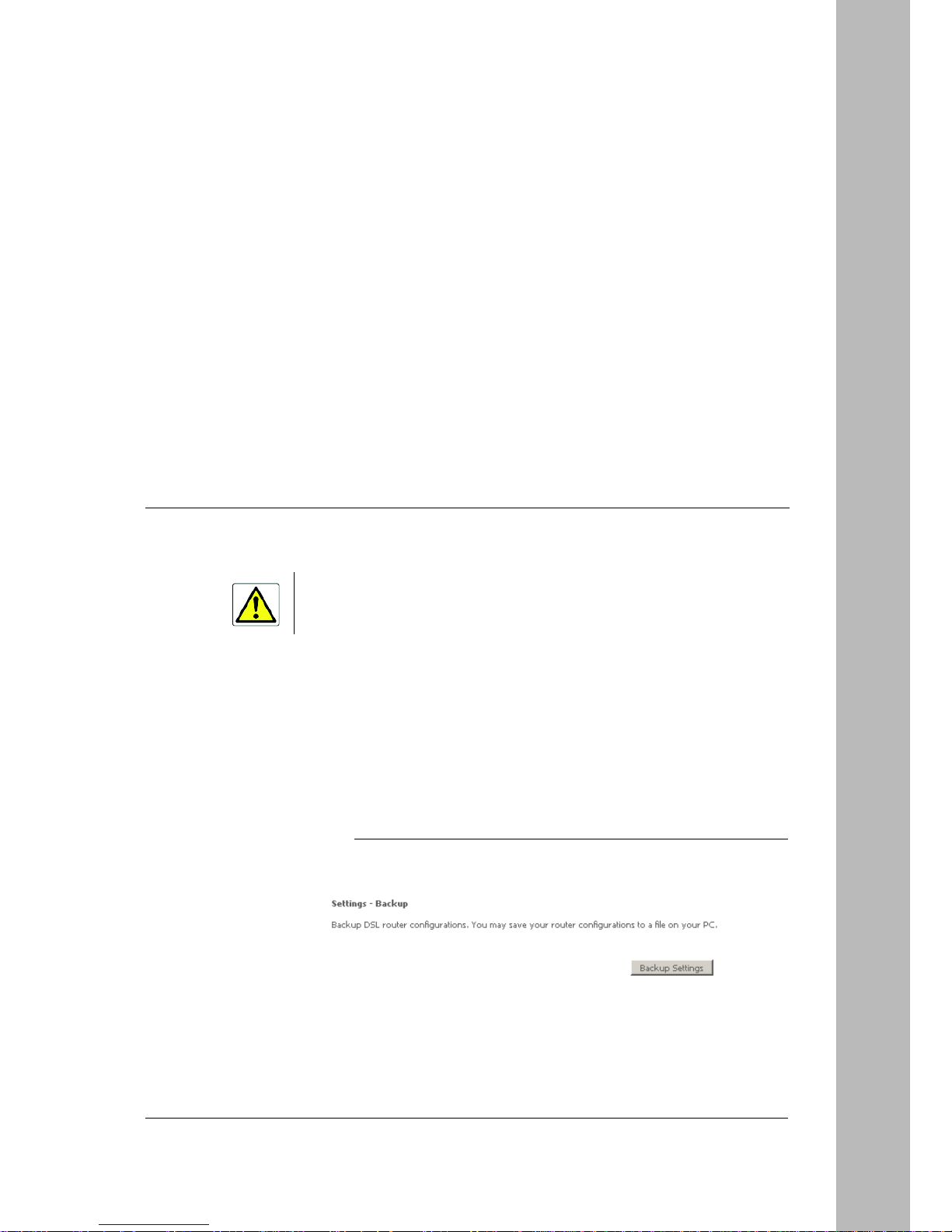
SETTINGS BACKUP By selecting Settings Backup, the page, shown in Figure 1, is
shown. By means oif this page it will be possible to backup DSL
router configuration.
FIGURE 1. Backup Panel
Be aware that any configuration change could compromise your connectivity.
Page 70
DISCUS™ Router
(C) (2006) Pirelli Broadband Solutions S.p.A. All Rights Reserved. Proprietary Use Pursuant to Cover Page Instructions.
64
OGU 930500118-A1
A pop-up screen will appear with a prompt to open or save the file to your computer.
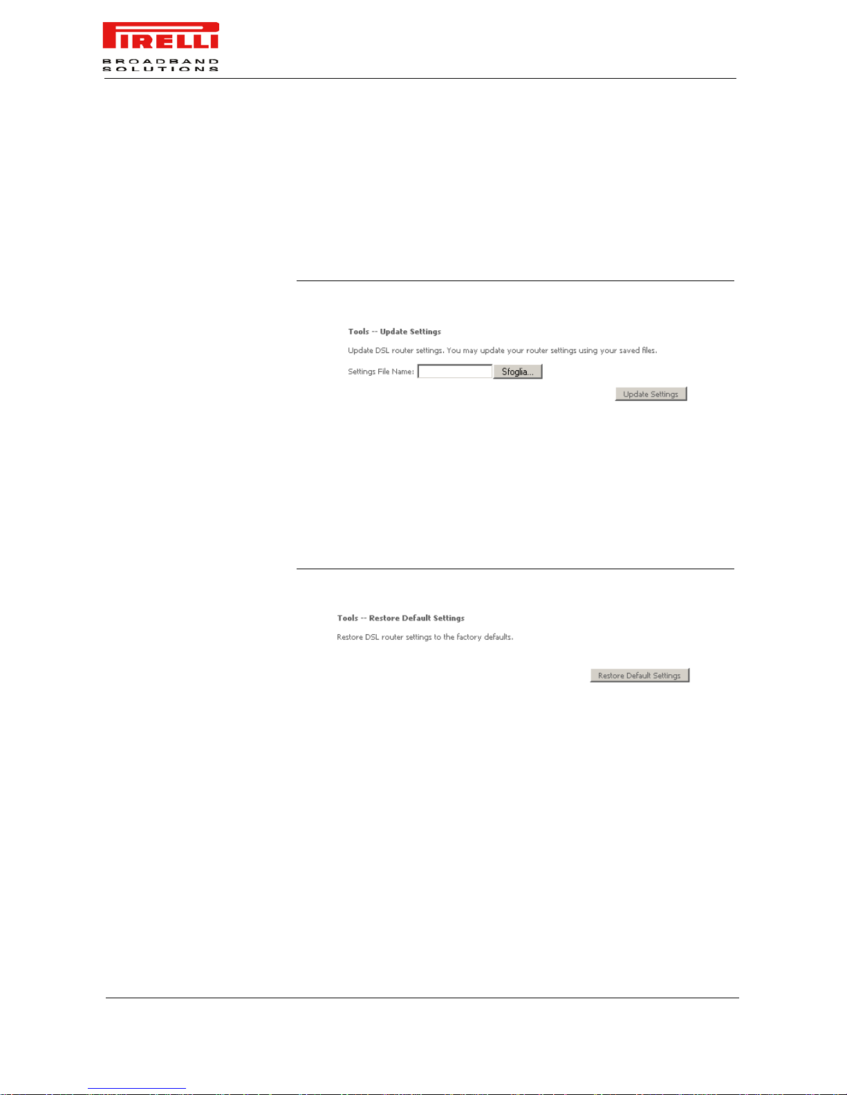
SETTINGS UPDATE To update DSL Router settings, do select the Settings >> Update item (see
Figure 2) and select a previously saved file. Then click on Update Settings
button.
FIGURE 2. Update Settings Panel
SETTINGS RESTORE Settings >> Restore Default Settings item will delete all current settings and
restore the router to factory default settings (see Figure 3). Click on the
Restore Default Settings button. Click on OK when the pop-up window
appears confirming that you want to restore factory default settings to your
router. The router will restore the default settings and reboot.
FIGURE 3. Restore Default Panel
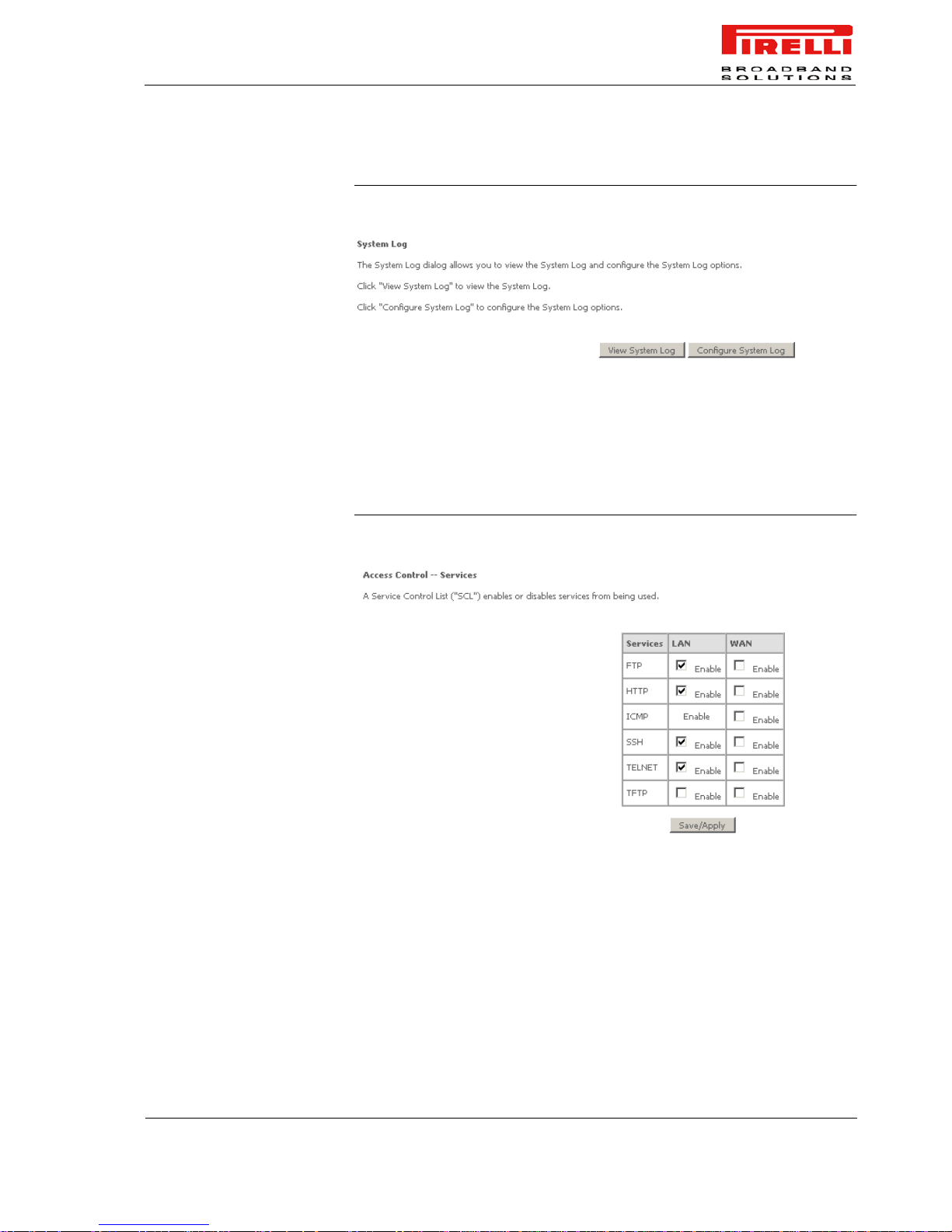
SYSTEM LOG The System Log item allows you to view the System Log and configure the
System Log options. To view the System Log click on the View System Log
button and check the log file.
Page 71
DISCUS™ Router
(C) (2006) Pirelli Broadband Solutions S.p.A. All Rights Reserved. Proprietary Use Pursuant to Cover Page Instructions.
65
OGU 930500118-A1
FIGURE 4. System Log Panel
ACCESS CONTROL >>
SERVICES
It is possible to enable or disable some services of your router by LAN or WAN.
If no WAN connection is defined, then only the LAN side can be configured.
Services that can be enabled include FTP, HTTP, ICMP, SSH, TELNET, and
TFTP. Click on Apply when finished.
FIGURE 5. Services Panel
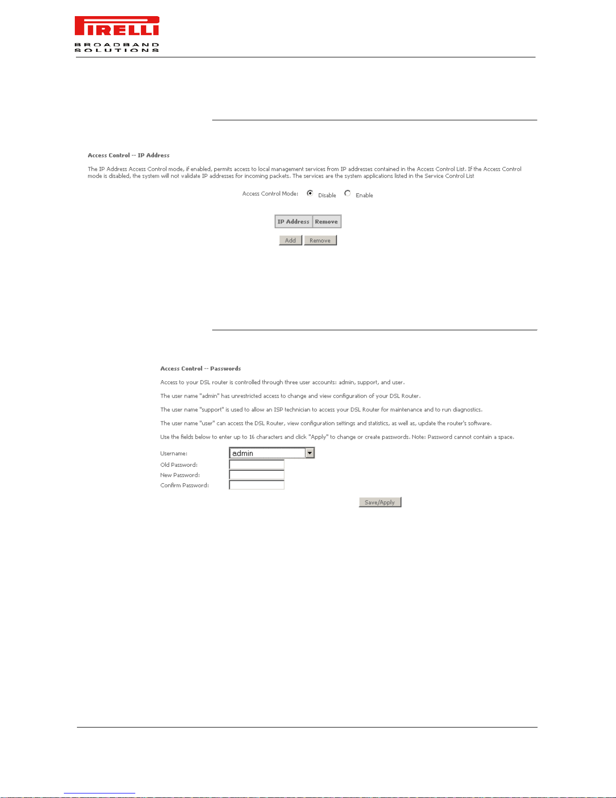
ACCESS CONTROL >> IP
ADDRESSES
Web access to the router can be limited when Access Control Mode is enabled.
The IP addresses of allowed hosts can be added using Access Control >> IP
Address.
Add the IP address to the IP address list by clicking on the Add button, then
select “Enabled” to enable Access Control Mode. To assign the IP address of
the management station that is per mitted to ac cess the local manag ement services, enter the IP address in the box and click on the Save/Apply button.
Page 72
DISCUS™ Router
(C) (2006) Pirelli Broadband Solutions S.p.A. All Rights Reserved. Proprietary Use Pursuant to Cover Page Instructions.
66
OGU 930500118-A1
FIGURE 6. IP Addresses Panel
ACCESS CONTROL >>
PASSWORDS
Access the Passwords screen under the Access Control section to change a
password. Select an account and ente r the cu rren t password and the new password and then click on the Save/Apply button.
FIGURE 7. Passwords Panel
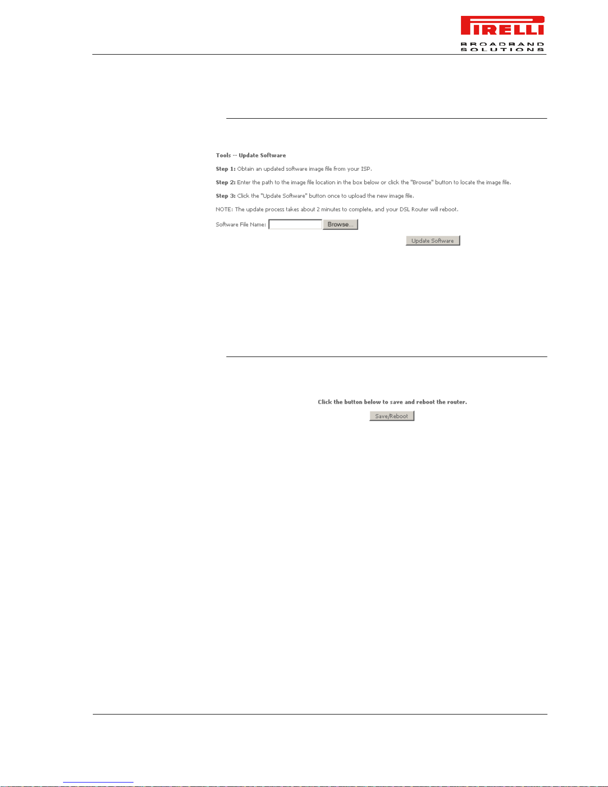
UPDATE SOFTWARE If your ISP releases new software for this router, follow these steps to perform
an upgrade.
1. Obtain an updated software image file from your ISP.
2. Enter the path to the image file location or click on the Browse button to
locate the image file.
3. Click the Update Software button once to upload the new image file.
Page 73
DISCUS™ Router
(C) (2006) Pirelli Broadband Solutions S.p.A. All Rights Reserved. Proprietary Use Pursuant to Cover Page Instructions.
67
OGU 930500118-A1
FIGURE 8. Update Software
SAVE / REBOOT Click the Save/Reboot button to reboot the router using the web interface. The
router will save the current configuration and reboot itself using the new configuration.
FIGURE 9. Save / Reboot Panel
Page 74

DISCUS™ Router
(C) (2006) Pirelli Broadband Solutions S.p.A. All Rights Reserved. Proprietary Use Pursuant to Cover Page Instructions.
68
OGU 930500118-A1
Page 75

(C) (2006) Pirelli Broadband Solutions S.p.A. All Rights Reserved. Proprietary Use Pursuant to Cover Page Instructions.
69OGU 930500118-A1
Troubleshooting
BASIC CONNECTION
CHECKS
• Check that the Router is connected to your computers and to the telephone line,
and that all the equipment is powered on. Check that the ETH or USB Status
(according to your connection type) and DSL LEDs on the Router are illuminated,
and that any corresponding LEDs on the NIC are also illuminated.
• Ensure that the computers have completed their start-up procedure and are ready
for use. Some network interfaces may not be correctly initialized until the start-up
procedure has completed.
• If the link status LED does not illuminate for a port that is connected, check that
you do not have a faulty cable. Try a different cable.
BROWSING TO THE
ROUTER CONFIGURATION
SCREENS
If you have connected your Router and computers together but cannot browse to the Router configuration screens, check the following:
•
Confirm that the physical connection between your computer and the Router is
OK, and that the ETH Status LEDs on the Router and NIC are illuminated. Some
NICs do not have status LEDs, in which case a diagnostic program may be available that can give you this information.
• Ensure that you have configured your computer as described in “Setting Up Your
Computer” on page 15. Restart your computer while it is connected to the Router
to ensure that your computer receives an IP address.
• When entering the address of the Router into your web browser, ensure that you
use the full URL including the “http://” prefix (e.g. http://192.168.1.1).
• Ensure that you do not have a Web proxy enabled on your computer. Go to the
Control Panel and click on Internet Options. Select the Connections tab and click
on the LAN Settings button at the bottom. Make sure that the Proxy Server option
is unchecked.
• If you cannot browse to the Router, use the winipcfg utility in Windows 98/ME to
verify that your computer has received the correct address information from the
Router. Fr om the Start menu, choose Run and then enter winipcfg. Check that the
computer has an IP address of the form 192.168.1.xxx (where xxx is in the range
2-254), the subnet mask is 255.255.255.0, and the default Router is 192.168.1.1
Page 76
DISCUS™ Router
(C) (2006) Pirelli Broadband Solutions S.p.A. All Rights Reserved. Proprietary Use Pursuant to Cover Page Instructions.
70
OGU 930500118-A1
(the address of the Router). If these are not correct, use the Release and Renew functions to
obtain a new IP address from the Router. Under Windows 2000 and Windows XP, use the
ipconfig command-line utility to perform the same functions.
CONNECTING TO THE
INTERNET
If you can browse to the Rout e r configuration screens but cannot access sites
on the Internet, check the following:
•
Confirm that the physical connection between the Router and the telephone line is OK, and
that the DSL LED on the Router is GREEN on.
• Ensure that you have entered the correct information into the Router configuration screens as
required. Use the “Internet Settings” screen to verify this.
• Check that the user name and password are correct.
• Check that the INTERNET LED is green on
• Ensure that your computers are not configured to use a Web proxy. On Windows computers,
this can be found under Control Panel >Internet Options > Connections.
FORGOTTEN PASSWORD
AND RESET
CONFIGURATION TO
FACTORY DEFAULTS
If you can browse to the Router configuration screen but cannot log on
because you do not know or have forgotten the password, follow the steps
below to reset the Router to it’s factory default configuration.
1. Switch off the Router.
2. Disconnect all your computers and the telephone line from the Router.
3. Re-apply power to the Router, and wait for it to finish booting up.
4. Press the Reset Configuration to Factory Default button on the rear panel for a
while.
5. The Router will restart, and when the start-up sequence has completed, browse to:
http://192.168.1.1 and configure your network.
6. Reconnect your network as it was before.
FREQUENTLY ASKED
QUESTIONS
How do I reset the Router to Factory Defaults? Press the Restore Configu-
ration to Factory Default button for more than 10 seconds.
How many computers on the LAN does the Router support? Up to a max-
imum of 256 computers on the LAN are supported.
How are additional computers connected? You can expand the number of
connections available on your LAN by using hubs, switches and wireless
access points connected to the Router. Wireless access points and hubs and
switches provide a simple, reliable means of expanding your network; contact
your supplier for more information, or visit: http://www.pirelli.com/
All your configuration changes will be lost, and you will need to configure again your network before you
can re-establish your Router connection to the Internet. Also, other computer users will lose their network connections whilst this process is taking place, so choose a time when this would be convenient.
The Quality of Service (QoS) is related to the guaranteed level of throughput (the amount of
data transferred from the Router to the clients). As many clients are connected as lower is
the Quality as Service.
Page 77

DISCUS™ Router
(C) (2006) Pirelli Broadband Solutions S.p.A. All Rights Reserved. Proprietary Use Pursuant to Cover Page Instructions.
71
OGU 930500118-A1
I connected the modem before installing the USB Drivers. How should I
proceed? You must unplug the USB cable, r estart your computer and start over
following the procedure described at chapter “USB Connection >> MS Windows”
Why sometimes the Internet Connection is slo w? It happens th at sometimes
a network congestion may produce a slower connection. Try again in a different
day period: if you experience many times this fact, contact your network provider.
Page 78
72
OGU 930500118-A1
Safety Information
Important Safety Information
This appendix contains directions that you must follow for your personal safety.
Follow all directions carefully. You must read the following safety information carefully before you install or
remove the unit.
- Use only the power adapter that is supplied with the unit. The use of an alternative
adapter can damage the Router and invalidate the warranty.
- Use an electrical outlet within easy distance and do not damage the power cable.
- To avoid electrical shock, do not open the Router.
- To prevent fire or shock hazard, do not expose your Router to rain or moisture, liquid
and toxic substances.
- Particular care must be taken during installation and removal of cables and telephone line.
- Never touch uninsulated telephone wire or terminals unless the telephone line has
been disconnected at the network interface.
- Ensure the correct ventilation to the Router. Do not obstruct the air conducts and do
not lean anything over.
- V erify to place the Router out of direct sunlight and away from sources of heat.
- Avoid using your Router during an electrical storm.
- The Router generates and uses Radio Frequency (RF) energy. In some environments, the use of RF energy is not permitted. The user should seek local advice on
whether or not RF energy is permitted within the area of intended use.
A
Page 79

73
OGU 930500118-A1
The crossed-out wheeled bin symbol on this electr ic or electro nic eq uipme nt, or on its
packaging, indicates that, at the end of its life, it must not be disposed of as unsorted
household waste. Instead it must be separately collected.
As a consumer you must, therefore, us e th e s peci fic col lection schemes and, in particular, the municipal collection schemes provided for waste electrical and electronic
equipment.
The separate collection and appropria te treatment of the equipment at the time of disposal helps to conserve natural resources and to ensure that it is recycled in a manner
that protects human health and the environment from materials, components and substances that can be dangerous to the environment and harmful to human health.
Further more, the separate collection and appropriate treatment of the equipment, at
the time of disposal, facilitates its possible reuse or possible materials recovery.
Page 80

74
OGU 930500118-A1
IP Addressing
The Internet Protocol Suite
The Internet protocol suite consists of a well-defined set of communications protocols and several standard
application protocols. Transmission Control Protocol/Internet Protocol (TCP/IP) is probably the most widely
known and is a combination of two of the protocols (IP and TCP) working together. TCP/IP is an internationally
adopted and supported networking standard that provides connectivity between equipment from many vendors
over a wide variety of networking technologies.
Managing the Router over the NetworK
To manage a device over the network, the Router must be correctly configured with the following IP information:
• An IP address
• A Subnet Mask
IP Addresses and Subnet Masks
Each device on your network must have a unique IP address to operate correctly. An IP address identifies the
address of the device to which data is being sent and the ad dress of th e destination net work. IP addr esses ha v e
the format n.n.n.x where n is a decima l number between 0 and 255 and x is a number between 1 and 254 inclusive.
However, an IP Address alone is not enough to make your device operate. In addition to the IP address, you
need to set a subnet mask. All networks are divided into smaller sub-networks and a subnet mask is a number
that enables a device to identify the sub-network to which it is connected.
For your network to work correctly, all devices on the network must have:
• The same sub-network address.
• The same subnet mask.
The only value that will be different is the specific host device number. This value must always be unique .
An example IP address is ‘192.168.10.8’. However, the size of the network determines the structure of this IP
Address. In using the Router, you will probably only encounter two types of IP Address and subnet mask structures.
Type One
In a small network, the IP address of ‘192.168.10.8’ is split into two parts:
• Part one (‘192.168.10’) identifies the network on which the device resides.
• Part two (‘.8’) identifies the device within the network.
This type of IP Address operates on a subnet mask of ‘255 .255.255.0’.
Type Two
B
Page 81

75
OGU 930500118-A1
In larger networks, where there are more d evices, the IP address of ‘192.168.10.8’ is, ag ain, split int o tw o parts
but is structured differently:
• Part one (‘192.168’) identifie s the network on which the device resides.
• Part two (‘.10.8’) identifies the device within the network.
This type of IP Address operates on a subnet mask of ‘255.255.0.0’.
How does a Device Obtain an IP Address and Subnet Mask?
There are three different ways to obtain an IP address and the subnet mask. These are:
• Dynamic Host Configuration Protocol (DHCP) Addressing
• Static Addressing
• Automatic Addressing (Auto-IP Addressing)
DHCP Addressing
The Router contains a DHCP server , which allows computers on your network to obtain an IP address and subnet mask automatically. DHCP assigns a temporary IP address and subnet mask which gets reallocate d once
you disconnect from the network.
DHCP will work on any client Operating System. Also , using DHCP means that the same IP address and subnet
mask will never be duplicated for devices on the network. DHCP is particularly useful for networks with large
numbers of users on them.
Static Addressing
You must enter an IP Address and the subnet mask manually on every device. Using a static IP and subnet
mask means the address is permanently fixed.
Auto-IP Addressing
Network devices use automatic IP addressing if they are configured to acquire an address using DHCP but are
unable to contact a DHCP server. Automatic IP addressing is a scheme where devices allocate themselves an
IP address at random from the industry standard subnet of 169.254.x.x (with a subnet mask of 255.255.0.0). If
two devices allocate themselves the same address, the conflict is detected and one of the devices allocates
itself a new address. A uto matic IP addressing support was introduced b y Microsoft in the Windows 98 oper ating
system and is also supported in Windows 2000 and Windows XP.
Page 82

76
OGU 930500118-A1
Technical Specifications
This section lists the technical specifications for the DISCUS™ Router.
WAN Interface
N°1 Line port (RJ-11plug, inner pair) supporting the following standards:
- ADSL (G.992.1, G992.2, T1.413, G994.1, G.997.1)
- ADSL2 (G.992.3)
- ADSL2+ (G992.5)
Annex A/Annex B are available in different product version
LAN Interface
- N° 4 10/100BASE-T Ethernet ports (RJ-45 plug), compliant IEEE 802.3, with auto MDIX
and auto-negotiation. Ports can be configured in order to be dedicated to video traffic to/from
a STB
- N° 1 USB Device v1.1
DSL (ATM)
Features
AAL5 (ITU-T I.363.5)
UBR, VBR-nrt, VBR-rt, CBR traffic classes
Multiple VC/PPP connections
Classic IP (CLIP) and ARP over ATM, RFCs 1577, 2225
Multiple PPPoE connections on a single VC
Multi-protocol encapsulation over AAL5 bridging and routing, RFCs 1483, 2684
PPP over AAL5 (PPP oATM), RFC 2364
OAM (ITU-T I.610)
- F4, F5
- Loop-back
Encapsulation modes in ATM stack: LLC and VC-Mux
Routing/Bridging
Features
Routing:
- Static routing
- RIPv1, RIPv2
- IP Multicasting – IGMP v2, v3
Bridging:
- WAN-LAN transparent bridging
- Transparent bridging between LAN devices
- Automatic discovery of MAC addresses
- Spanning tree protocol
NAT
NAT
- NAT-NAPT, RFCs 3022
- Static NAT
- Static NAPT
C
Page 83

77
OGU 930500118-A1
QoS
- ATM QoS: UBR, VBR-nrt, VBR-rt, CBR.
- 802.1P/Q prioritization
- Diffserv (RFC2474, RFC2475) marking and queuing according to connection type, network
interface, MAC, IP, hostname, DSCP/ToS value, port number and application
- Port based QoS
Security
- Stateful Packet Inspection (SPI) Firewall
- IP protocol filtering
- Access Control
- Parental control
Remote
Management
DSL Forum TR-069 CPE Management Protocol:
- Auto- configuration and dynamic service provisioning
- Software/firmware image management
- Status and performance monitoring
- WEB GUI (HTTP-S web server
- TFTP, RFC 1350
- Telnet server
Environmental
Specifications
Temperature:
- Operating: +10° to 40° C
- Non Operating: -20° to 65°C
Relative Humidity:
- Operating: 10 to 85% non condensing
- Non Operating:5 to 95% non condensing
Power Adapter
- European Plug
- Primary: nominal voltage 220V-230V, 50 Hz;
- Secondary: 15V 0.8A.
Declaration of
Conformance
The product conforms to the relevant standards according to the regulation in Article 3.1.a
and 3.1.b of the R&TTE Directive 1999/5/EEC of the European Community
Standards applied:
- EN 55022
- EN 55024
- EN 61000-3-2
- EN 61000-3-3
- EN 60950-1
Page 84

78
OGU 930500118-A1
Glossary
802.11b
The IEEE specification for wireless Ethernet which allows speeds of up to 11 Mbps. The standard pro vides f or 1,
2, 5.5 and 11 Mbps data rates. The rates will switch automatically depending on range and environment.
802.11g
The IEEE specification for wireless Ethernet which allows speeds of up to 54 Mbps. The standard pro vides f or 6,
12, 24, 36, 48 and 54 Mbps data rates. The rates will s witch automatically depending on range and environment.
10BASE-T
The IEEE specification for 10 Mbps Ethernet over Category 3, 4 or 5 twisted pair cable.
100BASE-TX
The IEEE specification for 100 Mbps Fast Ethernet over Category 5 twisted-pair cable.
Access Point
An Access Point is a device through which wireless clients connect to other wireless clients and which acts as a
bridge between wireless clients and a wired network, such as Ethernet. Wireless clients can be moved anywhere within the coverage area of the access point and still connect with each other . If connected to an Ethernet
network, the access point monitors Ethernet traffic and forwards appropriate Ethernet messages to the wireless
network, while also monitoring wireless client radio traffic and forwarding wireless client messages to the Ethernet LAN.
Ad Hoc mode
Ad Hoc mode is a configuration supported by most wir eless clien ts. It is used to connect a peer to peer network
together without the use of an access point. It offers lower performance than infrastructure mode, which is the
mode the router uses. (see also Infrastructure mode.
Auto-negotiation
Some devices in the range support auto-negotiation. Auto-negotiation is where two devices sharing a link, automatically configure to use the best common speed. The order of preference (best first) is: 100BASE-TX full
duplex, 100BASE-TX half duplex, 10BASE-T full duple x, and 10BASE-T half duple x. Auto-negotiation is defined
in the IEEE 802.3 standard for Ethernet and is an operation that takes place in a few milliseconds.
Bandwidth
The information capacity, measured in bits per second, that a channel can transmit. The bandwidth of Ethernet
is 10 Mbps, the bandwidth of Fast Ethernet is 100 Mbps. The bandwidth for 802.11b wireless is 11Mbps.
D
Page 85

79
OGU 930500118-A1
Category 5 Cables
One of five grade s of Twisted Pair (TP) cabling defined b y the EIA/TIA-58 6 stand ard. Cate gory 5 can be used in
Ethernet (10BASE-T) and Fast Ethernet networks (100BASE-TX) and can transmit data up to speeds of 100
Mbps. Category 5 cabling is better to use for network cabling than Category 3, because it supports both Ethernet (10 Mbps) and Fast Ethernet (100 Mbps) speeds.
Channel
Similar to any radio device, the Wireless Cable/DSL router allows you to choose different radio channels in the
wireless spectrum. A channel is a particular frequency within the 2.4GHz spectrum within which the Router
operates.
Client
The term used to described the desktop PC that is connected to your network.
DHCP
Dynamic Host Configuration Protocol. This protocol automatically assigns an IP address for every computer on
your network. Windows 95, Windows 98 and Windows NT 4.0 contain software that assigns IP addresses to
workstations on a network. These assignments are made by the DHCP se rver software that runs on Windows
NT Server, and Windows 95 and Windows 98 will call the server to obtain the address . Windo ws 98 will allocate
itself an address if no DHCP server can be found.
DMZ
DMZ (Demilitarized Zone) is an area outside the fir ew all, to le t remote users t o ha v e access to items on y our network (Web site, FTP download and upload area, etc.).
DNS Server Address
DNS stands for Domain Name System, which allows Internet host computers to have a domain name (such as
pirelli.com) and one or more IP addresses (such as 192.168.10.8). A DNS server keeps a database of host computers and their respective domain names and IP addresses, so that when a domain name is requested (as in
typing “pirelli.com” into your Internet browser), the user is sent to the proper IP address. The DNS server
address used by the computers on your home network is the location of the DNS server your ISP has assigned.
DSL
Short for digital subscriber line, but is commonly used in reference to the asymmetric version of this technology
(ADSL) that allows data to be sent o v er e xisti ng copper te lephone lines a t data r ates of from 1.5 to 9 Mbps when
receiving data (known as the downstream rate) and from 16 to 640 Kbps when sending data (known as the
upstream rate). ADSL requires a special ADSL modem. ADSL is growing in po pularity as more areas around the
world gain access.
DSL modem
DSL stands for digital subscriber line . A DSL mo dem uses your existing phone lines to send and receiv e dat a at
high speeds.
Page 86

80
OGU 930500118-A1
Encryption
A method for providing a level of security to wireless data transmissions . The Rout er use s tw o levels of encryption; 40/64 bit and 128 bit. 128 bit is a more powerful level of encryption than 40/64 bit.
Ethernet
A LAN specification dev eloped jointl y by Xero x, Intel and Digital Equipment Corporation. Ethernet networks use
CSMA/CD to transmit packets at a rate of 10 Mbps over a variety of cables.
Ethernet Address
See MAC address.
Fast Ethernet
An Ethernet system that is designed to ope rate at 10 0 Mbp s.
Firewall
Electronic protection that prevents anyone outside of your network from seeing your files or damaging your
computers.
Full Duplex
A system that allows packets to be transmitted and received at the same time and, in effect, doubles the potential throughput of a link.
IEEE
Institute of Electrical and Electronics Engineers. This American organization was founded in 1963 and sets
standards for computers an d communications.
IETF
Internet Engineering Task Force. An organization responsible for providing engineering solutions for TCP/IP
networks. In the network management area, this group is responsible for the development of the SNMP protocol.
IGMP
The Internet Group Management Protocol (IGMP) is an Internet protocol that provides a way for an Internet
computer to report its multicast group membership to adjacent routers . Multicasting allo ws one computer on the
Internet to send content to multiple other computers that have identified themselves as interested in receiving
the originating computer's content. Multicasting can be used for such applications as updating the address
books of mobile computer users in the field, sending out company newsletters to a distribution list, and "broadcasting" high-bandwidth programs of streaming media to an audience that has "tuned in" by setting up a multicast group membership.
Page 87

81
OGU 930500118-A1
Infrastructure mode
Infrastructure mode is the wireless configuration supported by the Router. You will need to ensure all of your clients are set up to use infrastructure mode in order for them to communicate with the Access Point built into your
Router. (see also Ad Hoc mode)
IP
Internet Protocol. IP is a layer 3 network protocol that is the standard for sending data through a network. IP is
part of the TCP/IP set of protocols that describe the routing of packets to addressed de vices . An IP address consists of 32 bits divided into two or three fields: a network numbe r and a host number or a network number, a subnet number, and a host number.
IP Address
Internet Protocol Address. A unique identifier for a device attached to a network using TCP/IP. The address is
written as four octets separated with periods (full-stops), and is made up of a network section, an optional subnet section and a host section.
ISP
Internet Service Provider. An ISP is a busin ess that provides con nectivity to the Internet f or individuals and oth er
businesses or organizations.
LAN
Local Area Network. A network of end stations (such as PCs, printers, servers) and network devices (hubs and
switches) that cover a relatively small geographic area (usually not larger than a floor or building). LANs are
characterized by high transmission speeds over short distances (up to 1000 metres).
MAC
Media Access Control. A protocol specified by the IEEE for determining which devices hav e access to a network
at any one time.
MAC Address
Media Access Control Address. Also called the hard ware or ph ysical address . A la y er 2 a ddress associated with
a particular network device. Most de vices th at conn ect t o a L AN have a MAC address assigned to them as th ey
are used to identify other devices i n a network. MAC addresses are 6 bytes long.
Mbps
Megabits per second.
MDI/MDIX
In cable wiring, the concept of transmit and rece ive are from the perspective of the PC, which is wired as a
Media Dependant Interface (MDI). In MDI wiring, a PC transmits on pins 1 and 2. At the hub, switch, router, or
Page 88

82
OGU 930500118-A1
access point, the perspective is reversed, and the hub receives on pins 1 and 2. This wiring is referred to as
Media Dependant Interface - Crossover (MDI-X).
NAT
Network Address Translation. NAT enables all the computers on your network to share one IP address . The
NAT capability of the Router allows you to access the Internet from any computer on your home network without having to purchase more IP addresses from your ISP.
Network
A Network is a collection of computers and other computer equipment that are connected for the purpose of
exchanging information or sharing resources. Networks vary in size, some are within a single room, others
span continents.
Network Interface Card (NIC)
A circuit board installed into a piece of computing equipment, f or e x ample , a computer, that enables you to co nnect it to the network. A NIC is also known as an adapter or adapter card.
Protocol
A set of rules for communication betw een devices on a network. The rules dictate format, timing, sequencing
and error control.
PSTN
Public Switched Telephone Network.
PPPoA
Point-to-Point Protocol over ATM. PPP over ATM is a protocol for connecting remote hosts to the Internet over
an always-on connection by simulating a dial-up connection.
PPPoE
Point-to-Point Protocol over Ethernet. Point-to-Point Protocol is a method of data transmission originally created for dial-up connections; PPPoE is for Ethernet connections.
RJ-45
A standard connector used to connect Ethernet networks. The “RJ” stan ds for “registered jack”.
Router
A device that acts as a central hu b by connecting to each computer's network interface card and man aging t he
data traffic between the local network and the Internet.
Server
Page 89

83
OGU 930500118-A1
A computer in a network that is shared by multiple end stat ions. Servers provide end stations with access to
shared network services such as computer files and printer queues.
SSID
Service Set Identifier. Some vendors of wireless products use SSID interchangeably with ESSID.
Subnet Address
An extension of the IP addressing scheme that allows a site to use a single IP network address for multiple p h ysical networks.
Subnet mask
A subnet mask, which may be a part of the TCP/IP information provided by your ISP, is a set of four numbers
configured like an IP address. It is used to create IP address numbers used only within a par ticular network (as
opposed to valid IP address numbers recognized by the Internet, which must assigned by InterNIC).
Subnets
A network that is a component of a larger network.
Switch
A device that interconnects se veral LANs to form a single logical LAN that comprises of several LAN segment s.
Switches are similar to bridges, in that they connect LA Ns of a different type; however they connect more LANs
than a bridge and are generally more sophisticated.
TCP/IP
Transmission Control Protocol/Internet Protocol. This is the name for two of the most well-known protocols
developed for the interconnection of networks. Originally a UNIX standard, TCP/IP is now supported on almost
all platforms, and is the protocol of the Internet .
TCP
It relates to the content of the data travelling through a network — ensuring that the information sent arrives in
one piece when it reaches its destination. IP relates to the address of the end station to which data is being sent ,
as well as the address of the destination networ k.
Traffic
The movement of dat a packets on a network.
Universal plug and play
Universal plug and play is a system which allows compatible app lications t o read some of thei r settin gs fr om the
Router. This allows them to automatically configure some, or all, of their settings and need less user configuration.
Page 90

84
OGU 930500118-A1
URL Filter
A URL Filter is a feature of a firewall that allows it to stop its clients form browsing inappropriate Web sites.
UTP
Unshielded twisted pair is the cable used by 10BASE-T and 100BASE-Tx Ethernet networks.
VCI
VCI - Virtual Channel Identifier. The identifier in the ATM (Asynchronous Transfer Mode) cell header that identifies to which virtual channel the cell belongs.
VPI
VPI - Virtual Path Identifier. The field in the ATM (Asynchronous Transfer Mode) cell header that identifies to
which VP (Virtual Path) the cell belongs.
WAN
Wide Area Network. A network that connects computers located in geo graphically sepa rate areas (f or e xample ,
different buildings, cities, or countries). The Internet is an example of a wide area netwo rk.
WEP
Wired Equivalent Privacy. A shared key encryption mechanism for wireless networking. Encryption strength is
40/64 bit or 128 bit.
Wi-Fi
Wireless Fidelity. This is the certification granted by WECA to products that meet their inter operability criteria.
(see also 802.11b, WECA)
Wi-Fi Alliance
Wireless Client
The term used to describe a desktop or mobile PC that is wirelessly connected to your wireless network
Wireless LAN Service Area
Another term for ESSID (Extended Service Set Identifier)
Wizard
A Windows application that automates a procedure such as installation or configuration.
Page 91

85
OGU 930500118-A1
WLAN
Wireless Local Area Network. A WLAN is a group of comp uters and d e vices connected together b y wir eless in a
relatively small area (such as a house or offi ce).
WPA
Wi-Fi Protected Access. A dynamically changing encryption mechanism for wirele ss networking. Encryption
strength is 256 bit.
Page 92

86
OGU 930500118-A1
Page 93

 Loading...