

Flight manual and
Maintenance manual
applies to Taurus ELECTRO G2
WARNING!
This booklet MUST be present inside the cockpit at all times!
Should you be selling the aircraft make sure this manual is handed over to the new owner.
REV. 0
(9 March, 2011)
This is the original manual of Pipistrel d.o.o. Ajdovščina
Should third-party translations to other languages contain any discreptancies,
Pipistrel d.o.o. Ajdovščina denies all responsibility.

2
TAURUS ELECTRO
www.pipistrel.si
REV. 0
Taurus model:
Factory serial number:
Date of manufacture:
Aircraft empty weight (kg):
Available crew weight (no front ballast):
Available crew weight (9 kg front ballast):
Available luggage weight:
List of equipment included in aircraft empty weight:
Date and place of issue: Ajdovščina,
To log into the Owner’s section, receive updates and Service Bulletins, go to: www.pipistrel.si and log in
the top right corner of the page with:
Username: owner1
Password: ab2008
THANK YOU!
3
TAURUS ELECTRO
www.pipistrel.si
REV. 0
Flight manual and
Maintenance manual for
Model: Taurus ELECTRO
Data Sheet:
Factory serial number:
Registration number:
Date of Issue: March, 2011
Pages signed under “Approval” in section Index of revisions and List of valid pages
(pages 4 and 5 of this manual) are approved by:
Authority: SLO.DOA.002
Signature:
Stamp:
Original date of Approval: March, 2011
This aircraft is to be operated in compliance with information and limitations contained herein.
The original English Language edition of this manual has been approved as operating instruction
according to “Pravilnik o ultralahkih letalnih napravah” of Republic of Slovenia.
Approval of translation has been done by best knowledge and judgement.
Pipistrel d.o.o. Ajdovščina, Goriška cesta 50a, SI- 5270 Ajdovščina, Slovenija
tel: +386 (0)5 3663 873, fax: +386 (0)5 3661 263, e-mail: info@pipistrel.si
www.pipistrel.si
Taurus ELECTRO

4
TAURUS ELECTRO
www.pipistrel.si
REV. 0
Index of revisions
Enter and sign the list of revised pages in the manual into the spaces provided below. All revised pages
should be clearly designated in the upper right corner of the page, also, any changes in page content
should be clearly visible (e.g. marked with a bold black vertical line).
Name of
revision
Reason for
Revision:
Revision no.,
date:
Description:
Affected
pages:
Approval,
signature:
Original /
Rev. 0
9 March, 2011
First original release. / Tomazic

5
TAURUS ELECTRO
www.pipistrel.si
REV. 0
List of valid pages
This manual contains 96 original and revised pages listed below.
Pages
State
(Revision)
Approval:
Cover
REV. 0
Page numbering
REV. 0
Authority approval sheet
3 REV. 0
Index of revisions
4 REV. 0
List of valid pages
5 REV. 0
Table of contents
7 REV. 0
General
9 - 12 REV. 0
Limitations
13 - 20 REV. 0
Emergency procedures
21 - 28 REV. 0
Normal procedures
29 - 42 REV. 0
Performance
43 - 51 REV. 0
Weight and balance
53 - 59 REV. 0
Aircraft and systems on board
61 - 73 REV. 0
Handling and maintenance
75 - 84 REV. 0
Appendix
85 - 93 REV. 0
CAUTION!
This manual is valid only if it contains all of the original and revised pages listed above.

6
TAURUS ELECTRO
www.pipistrel.si
REV. 0
This page is intentionally left blank.

7
TAURUS ELECTRO
www.pipistrel.si
REV. 0
Table of contents
General
Limitations
Emergency procedures
Normal procedures
Performance
Weight and balance
Aircraft and systems on board
Handling and maintenance
Appendix

8
TAURUS ELECTRO
www.pipistrel.si
REV. 0
This page is intentionally left blank.

9
TAURUS ELECTRO
www.pipistrel.si
REV. 0
Introduction
Notes and remarks
Technical data
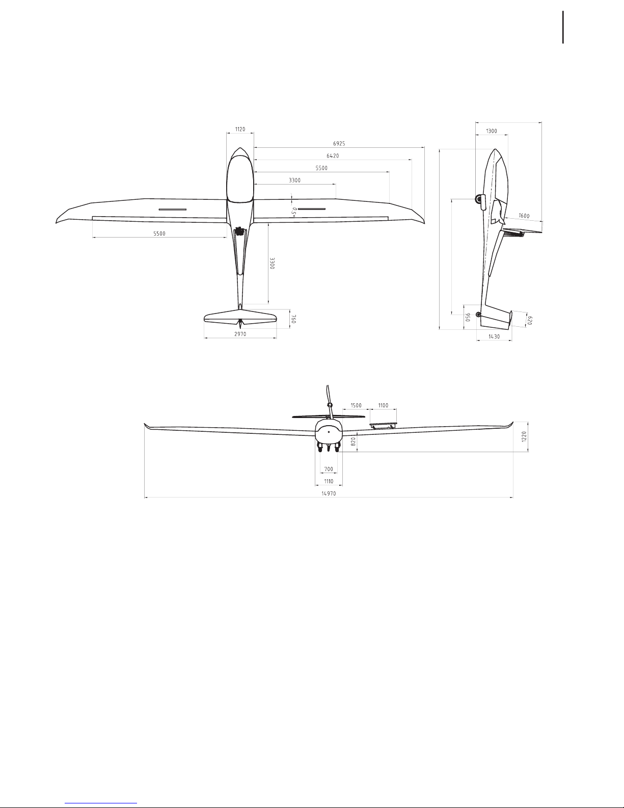
3-view drawing
General
General

TAURUS ELECTRO
www.pipistrel.si
Introduction
This manual contains all information needed
for appropriate and safe use of Taurus Electro
IT IS MANDATORY TO CAREFULLY
STUDY THIS MANUAL PRIOR TO USE
OF AIRCRAFT
In case of aircraft damage or people injury
resulting form disobeying instructions in the
manual PIPISTREL d.o.o. Ajdovscina denies all
responsibility.
All text, design, layout and graphics are
owned by PIPISTREL d.o.o. Ajdovscina
Therefore this manual and any of its contents
may not be copied or distributed in any manner (electronic, web or printed) without the
prior consent of PIPISTREL d.o.o. Ajdovscina
Notes and remarks
Safety definitions used in the manual:
WARNING! DISREGARDING THE FOLLOWING INSTRUCTIONS WILL LEAD TO SEVERE
DETERIORATION OF FLIGHT SAFETY AND HAZARDOUS SITUATIONS, INCLUDING SUCH
RESULTING IN INJURY AND LOSS OF LIFE.
CAUTION! DISREGARDING THE FOLLOWING INSTRUCTIONS WILL LEAD TO SERIOUS
DETERIORATION OF FLIGHT SAFETY.
Technical data
PROPORTIONS ELECTRO
wing span 14.97 m
length 7.30 m
height (propeller extended)
2.7 m
wing area
12.26 m
2
vertical tail area 0.86 m
2
horizontal stabilizer and elevator area 1.275 m
2
aspect ratio 18.30
positive flap deflection (down)
5°, 9 °, 18 °
negative flap deflection (up)
-5°
centre of gravity (% of MAC)
23% - 45%
General
TAURUS ELECTRO
www.pipistrel.si
3-view drawing
General

TAURUS ELECTRO
www.pipistrel.si
This page is intentionally left blank.

TAURUS ELECTRO
www.pipistrel.si
Introduction
Operational velocities
Motor, fuel, oil
Weight limits
Centre of gravity limits
Manoeuvre limits
G-load factors
Cockpit crew
Types of operations
Minimum equipment list
Other restrictions
Warning placards
Limitations

TAURUS ELECTRO
www.pipistrel.si
Operational velocities
Speed limits
Velocity
Velocity never to be
exceeded
Never exceed this speed. Should the VNE be
exceeded, land as soon as possible and have
the aircraft verified for airworthiness by authorised service personnel.
extended.
VPO
or retract powerplant
this speed.
VRA
Also known as Vb. Turbulence penetration
speed.
VA
VFE
extended
extended.
airbrake extention
speed. Once fully extended, VNE is the limit.
VLO
above this speed
Airspeed indicator markings
white arc
Speed range where flaps may be extended. Lower end is de-
fined as 110% of VS (stall speed in landing configuration at
green arc
Speed range of normal operation. Lower end is defined as
sition), upper end is limited by VRA (see above).
yellow arc
Y
)
Introduction
This chapter provides information about operational restrictions, instrument markings and basic
knowledge on safe operation of aircraft, motor and on-board appliances.
WARNING! ABOVE PRESSURE ALTITUDE OF 1000 METERS 3300 FT ALL SPEED LIM
ITS MUST BE TREATED AS TRUE AIRSPEED TAS.
INDICATED AIRSPEED IAS MUST BE REDUCED ACCORDINGLY!

TAURUS ELECTRO
www.pipistrel.si
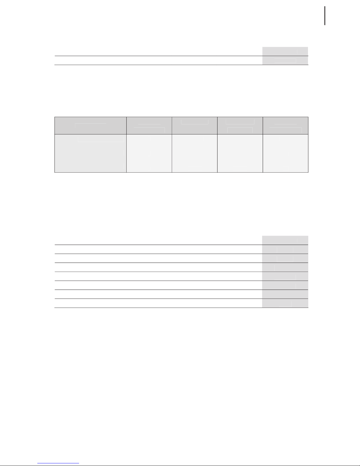
VNE at altitude (standard ICAO atmosphere)
The tables below indicate IAS to TAS relation for an altitude span of 0 - 5000m (0 - FL165) in different
atmospheres (variable is temperature). TAS is a constant of 225 km/h (122 kts) - VNE for the entire tables.
Altitude (meters)
Altitude (meters)
0
500
2000
2500
3000
3500
4000
4500
5000
Altitude (flight level)
0
VNE IAS (km/h)
VNE IAS (km/h)
225
225
223
218
213
209
203
VNE IAS (kts)
Altitude (meters)
Altitude (meters)
0
500
2000
2500
3000
3500
4000
4500
5000
Altitude (flight level)
0
VNE IAS (km/h)
225
219
209
205
VNE IAS (kts)
98
Altitude (meters)
Altitude (meters)
0
500
2000
2500
3000
3500
4000
4500
5000
Altitude (flight level)
Altitude (flight level)
0
VNE IAS (km/h)
225
220
215
210
205
201
VNE IAS (kts)
98
96
Altitude (meters)
Altitude (meters)
0
500
2000
2500
3000
3500
4000
4500
5000
Altitude (flight level)
0
VNE IAS (km/h)
220
215
206
202
VNE IAS (kts)
999794
:
Altitude (meters)
Altitude (meters)
0
500
2000
2500
3000
3500
4000
4500
5000
Altitude (flight level)
0
VNE IAS (km/h)
216
207
202
VNE IAS (kts)
999794
92
Note how VNE decreases at higher altitudes!
WARNING! RESPECT THE LISTED VALUES AT ALL TIMES, NOT TO EXCEED FLUTTER CRITI
CAL SPEED.
Indicated airspeed (IAS) to true airspeed (TAS) relation
Airspeed indicator measures the difference between total and static pressure (also called dynamic
pressure), which does not only change as speed increases, but is also linked with altitude. Flying at
high altitudes, where the air is getting thinner, results in misinterpreting airspeed which is being
indicated. The indicated airspeed value is actually lower than the true airspeed to which the aircraft
is exposed. The higher you fly, the bigger the difference between IAS and TAS. Be aware of this effect
especially when flying at high altitude at high speeds, not to exceed VNE unawarely. Bear in mind
this can happen even with the indicator still pointing within the yellow arc!
TAURUS ELECTRO
www.pipistrel.si
Motor/controller, Battery System
Motor types: ELECTRO40/30
WARNING! The motor is not certified for aviation use, therefore, there is no assur-
ance it cannot fail in its operation at any given moment, without prior notice.
The motor
TEMPERATURE °C / ELECTROMOTOR
40 kW
30 kW
40° C
2200
take-off rpm (typical)
2150
climb rpm (typical)
Controller
45-55° C
WARNING! DO NOT, UNDER ANY CIRCUMSTANCES, ATTEMPT TO USE ANY OTHER
BATTERIES, OTHER THAN PIPISTREL FACTORY ORIGINAL BATTERY SYSTEM, WITH THIS MOTOR/
CONTROLLER
Battery system
Standard
270 V
230 V - 250 V
5° C
Allowable temperature range for storage
CAUTION! TEMPERATURES BELOW 10°C WILL RESULT IN DECREASE OF BATTERY CAPACITY.
PLAN YOUR FLIGHT ACCORDINGLY.
WARNING! DO NOT, UNDER ANY CIRCUMSTANCES, ATTEMPT TO CHARGE THE BATTERIES
WITH ANY THIRD PARTY CHARGERS. ONLY PIPISTREL ORIGINAL EQUIPMENT MUST BE USED.
WARNING! RESPECT OPERATING AND STORAGE TEMPERATURE LIMITS AT ALL TIMES.
FAILURE TO DO SO MAY RESULT IN BATTERY DAMAGE.
TAURUS ELECTRO
www.pipistrel.si
Propeller
TAURUS
fixed pitch (wooden or composite)
Motor instrument markings
WARNING! USER IS TO FILL IN MOTOR SPECIFIC VALUES.
Green arc
Yellow arc
Tachometer (RPM)
Controller temp. (°C)
/
/
5
0-2150
5-55
2150-2200
55-70
50-70
2200
Weight limits
Taurus electro basic model weights
WEIGHT
empty aircraft weight (incl. parachute rescue system), std battery system
306 kg
empty aircraft weight (incl. parachute rescue system), optional batteries sys.
323 kg
472.5 kg
see p. 55
see p. 55
water ballance reservoir (max weight)
9 kg
allowable luggage weight
WARNING! SHOULD ONE OF THE ABOVELISTED VALUES BE EXCEEDED, OTHERS MUST BE
REDUCED IN ORDER TO KEEP MTOM BELOW 472.5 KG. MAKE SURE MAXIMUM AND MINIMUM
COCKPIT CREW WEIGHT AS WELL AS AVAILABLE LUGGAGE WEIGHT ARE ALWAYS KEPT WITHIN
ALLOWABLE LIMITS. FAILING TO COMPLY WITH ANY OF THE WEIGHT LIMITATIONS MAY RESULT
IN AIRCRAFT BEING UNCONTROLLABLE ON GROUND AND/OR IN FLIGHT DUE TO EXTREME
CENTRE OF GRAVITY POSITION.
WARNING! CHECK THE WATER BALANCE RESERVOIR IN FRONTCABIN AND VERIFY
CREW’S WEIGHT BEFORE EVERY FLIGHT AS IT MAY INFLUENCE THE CENTRE OF GRAVITY OF
AIRCRAFT TO THE POINT WHERE IT IS NO LONGER CONTROLLABLE!

TAURUS ELECTRO
www.pipistrel.si
Centre of gravity limits
•
Aircraft's safe centre of gravity position ranges between 23% and 45% of MAC (Mean
Aerodynamic Chord)
•
C.G. point ranges between 238 mm and 429 mm aft of datum, datum is leading edge
of wing root.
Manoeuvre limits
Taurus Electro is certified as an Ultralight aircraft. Therefore, no aerobatic manoeuvers
are permitted.
WARNING! FLYING IN CONSIDERABLE SIDESLIP WHEN THE MOTOR IS EXTENDED AND
RUNNING MAY DAMAGE THE MOTORPROPELLER ASSEMBLY. YOU ARE STRONGLY DISCOUR
AGED FROM SIDESLIPPING WHEN MOTOR IS EXTENDED AND RUNNING!
G-load factors
at VA at VNE
max. positive wing load:
+ 5.3 G + 4.0 G
max. negative wing load:
– 2.65 G – 1.5 G
Cockpit crew
•
Actual minumum and maximum combined cockpit crew weight heavily depend on the
centre of gravity of an empty aircraft. Minumum and maximum combined cockpit crew
weight is determined after weighing the aircraft each time. Procedure for the determination of minimum and maximum combined cockpit crew weight can be found on
page 57 of this manual. Inside the cockpit, there must be a clearly visible placard stating
the minimum and maximum combined weight of the crew.
•
Maximum takeoff weight (MTOW) MUST NOT, under any circumstances, exceed 472.5
kg.
Types of operations
Taurus Electro is built to fly under day visual flight rules
(day VFR). Flight into known icing conditions or rain is prohibited.

TAURUS ELECTRO
www.pipistrel.si
WARNING! SHOULD YOU FIND WATER DROPS ON THE AIRFRAME DURING PREFLIGHT
CHECKUP AT TEMPERATURES CLOSE TO FREEZING, YOU MAY EXPECT ICING TO APPEAR IN
FLIGHT. AIRBRAKES ARE ESPECIALLY PRONE TO ICING UNDER SUCH CIRCUMSTANCES. AS
WATER MAY ACCUMULATE UNDERNEATH THE TOP PLATES, SPOILERS MAY FREEZE TO THE
WING SURFACE. SHOULD THIS OCCUR, YOU WILL MOST DEFINITELY BE UNABLE TO EXTEND
SPOILERS BEFORE THE ICE MELTS. THEREFORE, FLYING UNDER CIRCUMSTANCES MENTIONED
ABOVE, IT IS RECOMMENDED TO EXTEND AND RETRACT THE SPOILERS IN FLIGHT FREQUENT
LY TO PREVENT ITS SURFACE FREEZING TO THE AIRFRAME.
Minimum equipment list
• Airspeed indicator (functional)
• Altimeter (functional)
• Compass (functional)
• Electric System Manager instrument (ESYS-MAN)
• Battery Management System (BMS, functional)
• Parachute rescue system (where required legally)
Other restrictions
Due to flight safety reasons it is forbidden to:
•
fly in any rainfall;
•
fly during thunderstorm activity;
•
fly in a blizzard;
•
fly according to instrumental flight rules (IFR) or attempt to fly in zero visibility conditions (IMC);
•
fly when outside air temperature (OAT) reaches 40°C or higher;
•
perform any form of aerobatic flying;
•
take off and land with flaps retracted or set to negative (-5°) position;
•
take off with spoilers extended.
•
store the aircraft outside in the rain.
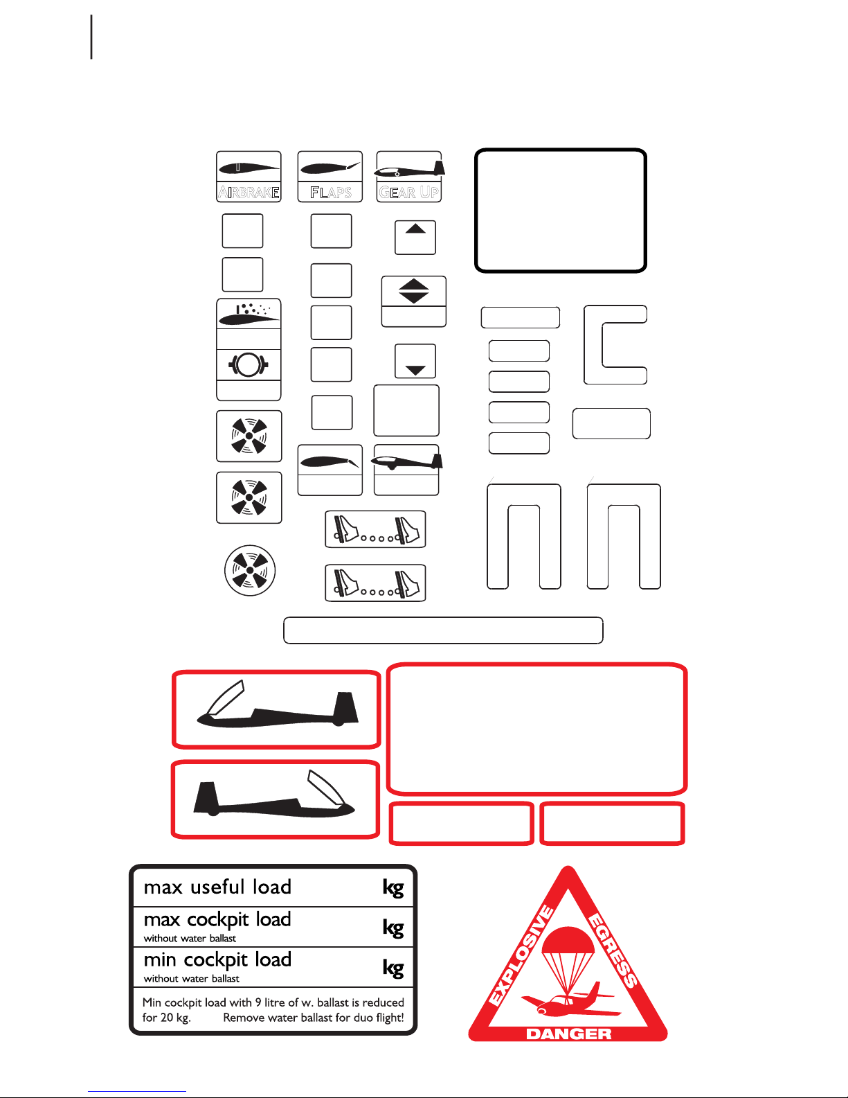
Warning placards
Taurus Electro is categorised as an Ultralight aircraft and must wear a
warning placard as such. The placard indicates the
aircraft is not certified according to EASA standards and is therefore flown
completely at pilot’s own risk
.
20
TAURUS ELECTRO
www.pipistrel.si
Placards
G
E
A
R
U
P
A
I
R
B
R
A
K
E
GEAR DN
F
L
A
P
S
FLAPS
TRIM
UP
DN
OUT
IN
0°
+5°
L
-5°
AIRBRAKE
GEAR BRK
pilot min. kg
pilot max. kg
EN GI N E RE TR A C T IO N
1. throttle idle, ignition off
2. reduce IAS to 75 km/h
3. after prop. stops IAS 90 km/h,
- engine DOWN
4. when prop. retracted
- master switch I
VARIO
RADIO AUX
XPDR
12V
socket
ENG
INST
ENG
SYSTEM
T
INTERCOM
ON
OFF
L MAGNETOS R
P
R
I
M
E
R
ON
OFF
THROTTLE
ON
OFF
F
U
E
L
SC MODE
ON
OFF
with 9kg nose ballast kg
with 9kg nose ballast kg
pilot min. kg
WARNING!
If battery is removed
M I C
HEADSET
ON
OFF
F
U
E
L

21
TAURUS ELECTRO
www.pipistrel.si
Introduction
Stall recovery
Spin recovery
Motor failure
Landing out
Motor fire
Smoke in cockpit
ESYS-MAN failure
Landing gear failure
Flutter
Exceeding VNE
Parachute rescue system

22
TAURUS ELECTRO
www.pipistrel.si
Introduction
This chapter provides information on how to react when confronted with typical flight hazards.
Stall recovery
First reduce angle of attack by easing-off on the control stick, then
1. If the motor is running, add full power.
2. Resume horizontal flight.
Spin recovery
Taurus Electro is constructed in such manner that it is difficult to be flown into a spin. However, once
spinning, react as follows:
1. If the motor is running, set throttle to idle (lever in full back position).
2. Apply full rudder deflection in the direction opposite the spin.
3. Lower the nose towards the ground to build speed (stick forward).
4. As the aircraft stops spinning neutralise rudder deflection.
5. Slowly pull up and regain horizontal flight.
Taurus Electro tends to re-establish rightened flight by itself usually after having spun for a mere 90°.
WARNING! KEEP THE CONTROL STICK CENTRED ALONG ITS LATERAL AXIS NO AILERON
DEFLECTIONS THROUGHOUT THE RECOVERY PHASE! DO NOT ATTEMPT TO STOP THE AIR
CRAFT FROM SPINNING USING AILERONS INSTEAD OF RUDDER!
WARNING! AFTER HAVING STOPPED SPINNING, RECOVERING FROM THE DIVE MUST BE
PERFORMED USING GENTLE STICK MOVEMENTS PULL, RATHER THAN OVERSTRESSING THE
AIRCRAFT. HOWEVER, VNE MUST NOT BE EXCEEDED DURING THIS MANOEUVRE.
When the aircraft is straight and level resume normal flight.
Motor failure
Motor failure during takeoff or initial climb
Ensure proper airspeed by lowering the nose and land the aircraft in runway heading, avoiding eventual obstacles in your way. Set master switch to OFF position (key full left).
Land straight ahead.
WARNING! DO NOT CHANGE COURSE OR MAKE TURNS IF THIS IS NOT OF VITAL
NECESSITY! AFTER HAVING LANDED SAFELY, ENSURE PROTECTION OF AIRCRAFT AND VACATE
THE RUNWAY TO KEEP THE RUNWAY CLEAR FOR ARRIVING AND DEPARTING TRAFFIC.
DO THIS CALMLY AND CAREFULLY NOT TO CAUSE DAMAGE TO YOURSELF AND EQUIPMENT.

23
TAURUS ELECTRO
www.pipistrel.si
Motor failure in climb
First ensure proper airspeed by lowering the nose, then start scanning the terrain underneath and
choose the most appropriate site for landing out.
WARNING! THE DECISION WHERE TO LAND WHEN LANDING OUT IS FINAL! CHANGING
YOUR MIND EVEN IF YOU HAPPEN TO COME ACROSS A DIFFERENT, PERHAPS MORE APPROPRI
ATE LANDING SITE, SHOULD BE YOUR LAST RESORT.
Provided the motor fails aloft, first retract the propulsion unit and prepare for an
emergency landing if the conditions prevent you from gliding to the airport.
Emergency landing
Propulsion unit retracted
1. Master switch OFF (key in full left position).
2. Fasten your seat belts tightly.
3. Approach and land with extreme caution with +10 km/h (+5 kts) airspeed reserve if
the chosen landing terrain lenght permits.
4. After having landed abandon the aircraft immediately.
Propulsion unit extended or refusing to retract
1. Your first priority is to fly the aircraft! Atempt to retract the propulsion unit by
setting the retraction switch up and back down IF your height is 300 m or higher.
Otherwise, proceed with emergency landing.
2. Fasten your seat belts tightly.
3. Master switch OFF (key in full left position).
4. Should the propulsion unit remain extended or partially retracted land the aircraft
onto the main wheels first in order to minimise vertical impact onto the propeller arm.
5. Fly no faster than minimum sink speed (94 km/h - 51 kts) during the approach as
more speed will only increase your rate of descent and use up to+10 km/h (+5 kts) airspeed reserve only before touchdown if the chosen landing terrain lenght permits.
The landing out manoeuvre MUST be preformed with regard to all normal flight parameters.

24
TAURUS ELECTRO
www.pipistrel.si
Fire
WARNING! USE ONLY WATERLESS FIRE EXTINGUISHING AGENTS TO EXTINGUISH ANY
FIRE ON THE AIRCRAFT!
Motor fire on ground
Should you encounter motor fire on ground, react as follows:
1. Come to a complete standstill, master switch OFF immediately and pull out the red
connector on the battery box behind the cockpit to disconnect the battery system.
Keep powerplant extended.
3. Abandon the aircraft and start fire extinguishing with a waterless agent.
WARNING! AFTER THE FIRE HAS BEEN EXTINGUISHED DO NOT ATTEMPT TO RESTART THE
MOTOR.
Motor fire in flight
1. Swich System enable swith off.
2. Open slide windows and set all ventilation devices to ON.
3. Perform side-slip (crab) manoeuvre in direction opposite the fire.
4. Perform emergency landing procedure and abandon the aircraft immediately.
Battery system fire
Land and abandon the aircraft as soon as possible.
WARNING! USE ONLY WATERLESS FIRE EXTINGUISHING AGENTS TO EXTINGUISH ANY
FIRE ON THE AIRCRAFT!
Smoke in cockpit
1. Leave the motor extended and set master switch to OFF.
2. Open slide windows and set all ventilation devices to ON for adequate breathing.
3. Land as soon as possible.
ESYS-MAN failure
With the motor retracted: Continue flying as a sailplane.
With the motor extended and not running: Look for a landing field to do a safe outlanding.
With the motor extended and running: Do not stop the motor. Fly to the next airfield and land.

25
TAURUS ELECTRO
www.pipistrel.si
Landing gear failure
Should the landing gear fail to lower, fasten your seatbelts tightly and perform a landing procedure
as normal. Use full flaps to have the minimum possible speed at touch-down.
Flare at the same altitude like you would normally and in the same manner. Avoid eventual obstacles
(bumps, fences etc. on the runway or strip where you are landing.
Flutter
Flutter is described as the oscillation of control surfaces. In most cases it is caused by abrupt control
deflections at speeds close or in excess of VNE. As it occurs, the ailerons, elevator or even the whole
aircraft start to vibrate violently.
Should flutter occur, pull on the stick (and reduce power immediately)!
WARNING! FLUTTERING OF AILERONS OR TAIL SURFACES MAY CAUSE PERMANENT
STRUCTURAL DAMAGE AND/OR INABILITY TO CONTROL THE AIRCRAFT.
AFTER A SAFE LANDING, THE AIRCRAFT MUST UNDERGO A SERIES OF CHECKUPS PER
FORMED BY AUTHORISED SERVICE PERSONNEL TO VERIFY AIRWORTHINESS.
Exceeding VNE
Should the VNE be exceeded, reduce airspeed slowly and continue flying using gentle control deflections. Land safely as soon as possible and have the aircraft verified for airworthiness by
authorised service personnel.
Parachute rescue system
Upon pulling the rescue system handle, the whole electrical system, including the propulsion
system, of the aircraft is disengaged immediately. See next page for further instructions.

26
TAURUS ELECTRO
www.pipistrel.si
Parachute rescue system
System description
Depending on the canopy size, the main canopy system is open and fully inflated above the aircraft
between 1.5 - 6.0 seconds after being fired with regard to the flight speed. This means that a rescue
can be successful from as little as 30 m to 150m over the ground, depending on the installation, position of the aircraft, its speed and trajectory. The necessary height needed for a rescue is deduced
from measured figures in horizontal flight up to the stated VNE of aircraft in its MTOW. These figures
are stated in the technical parameters of the system. It is possible to aim the rocket in any direction
but, the best direction is vertical to the lengthwise axis of the plane in an upward or slightly oblique
aft direction. The rocket system has been designed with sufficient power reserve so that it can pull
out the chute even under extreme conditions ranging in temperatures from -40°C up to +60°C.
WARNING! ACTIVATION HANDLE SAFETY PIN SHOULD BE INSERTED WHEN THE
AIRCRAFT IS PARKED OR HANGARED TO PREVENT ACCIDENTAL DEPLOYMENT.
HOWEVER, AS SOON AS THE PILOT BOARDS THE AIRCRAFT, SAFETY PIN MUST BE REMOVED!
Use of parachute rescue system
In situations such as:
•
structural failure
•
mid-air collision
•
loss of control over aircraft
•
motor failure over hostile terrain
•
pilot incapacitation (incl. heart attack, stroke, temp. blindness, disorientation...)
the parachute SHOULD be deployed.
Prior to firing the system:
•
shut down the motor and set master switch to OFF (key in full left position)
•
fasten safety harnesses tightly
•
protect your face and body.
To deploy the parachute jerk the activation handle (located above and between pilots)
hard for a length of at least 30 cm towards the instrument panel.
Once you have pulled the handle and the rocked is deployed, it will be less than two seconds before
you feel the impact produced by two forces. The first force is produced by stretching of all the system. The force follows after the inflation of the canopy from opening impact and it will seem to you
that the aircraft is pulled backwards briefly. The airspeed is reduced instantly and the aircraft now
starts do descent to the ground underneath the parachute.
As a pilot you should know that the phase following parachute deployment may be a great unknown and a great adventure for the crew. You will be getting into situation for the first time, where

27
TAURUS ELECTRO
www.pipistrel.si
a proper landing and the determination of the landing site are out of your control.
CAUTION! SHOULD YOU END UP IN POWER LINES CARRYING ELECTRICAL CURRENT, DO
NOT UNDER ANY CIRCUMSTANCES TOUCH ANY METAL PARTS INSIDE OR OUTSIDE THE COCK
PIT. THIS ALSO APPLIES TO ANYONE ATTEMPTING TO HELP OR RESCUE YOU. BE AWARE THAT
ANYONE TOUCHING A METAL PART WHILE STANDING ON THE GROUND WILL PROBABLY SUF
FER MAYOR INJURY OR DIE OF ELECTROCUTION. THEREFORE, YOU ARE STRONGLY ENCOUR
AGED TO CONFINE YOUR MOVEMENTS UNTIL QUALIFIED PERSONAL ARRIVE AT THE SITE TO
ASSIST YOU.
After the parachute rescue system has been used or if you suspect any possible damage to the system, do not hesitate and immediately contact the manufacturer!
Handling and maintenance of Parachute rescue system
Prior to every flight all visible parts of the system must be checked for proper condition. Special attention should be paid to eventual corrosion on the activation handle inside the cockpit. Also, main
fastening straps on the inside of the fuselage must remain undamaged at all times.
Furthermore, neither the system, nor any of its parts should be exposed to moisture, vibration and
UV radiation for long periods of time to ensure proper system operation and life.
CAUTION! IT IS STRONGLY RECOMMENCED TO THOROUGHLY INSPECT AND GREASE THE
ACTIVATION HANDLE, PREFERABLY USING SILICON OIL SPRAY, EVERY 50 FLIGHT HOURS.
All major repairs and damage repairs MUST be done by the
manufacturer or authorised service personnel.
For all details concerning the GRS rescue system, please see the “GRS - Galaxy Rescue System Manual
for Assembly and Use”.

28
TAURUS ELECTRO
www.pipistrel.si
This page is intentionally left blank.
29
TAURUS ELECTRO
www.pipistrel.si
Introduction
Assembling and
disassembling the
aircraft
Daily check-up
Preflight check-up
Normal procedures and
recommended speeds

30
TAURUS ELECTRO
www.pipistrel.si
Introduction
This chapter provides information on everything needed to fly Taurus Electro safely.
Assembling and disassembling the aircraft
CAUTION! PRIOR TO EACH ASSEMBLING OR DISASSEMBLING ACTION THE TAURUS Electro
SHOULD NOT BE PLACED UNDER STRONG SUNSHINE, AS COMPOSITE PARTS EXPAND AND
CONTRACT AND YOU MAY NOT BE ABLE TO ASSEMBLE OR DISASSEMBLE THE AIRFRAME. UNDER
NO CIRCUMSTANCES ATTEMPT TO ASSEMBLE OR DISASSEMBLE ANY PARTS OF THE AIRCRAFT
FURCEFULLY!
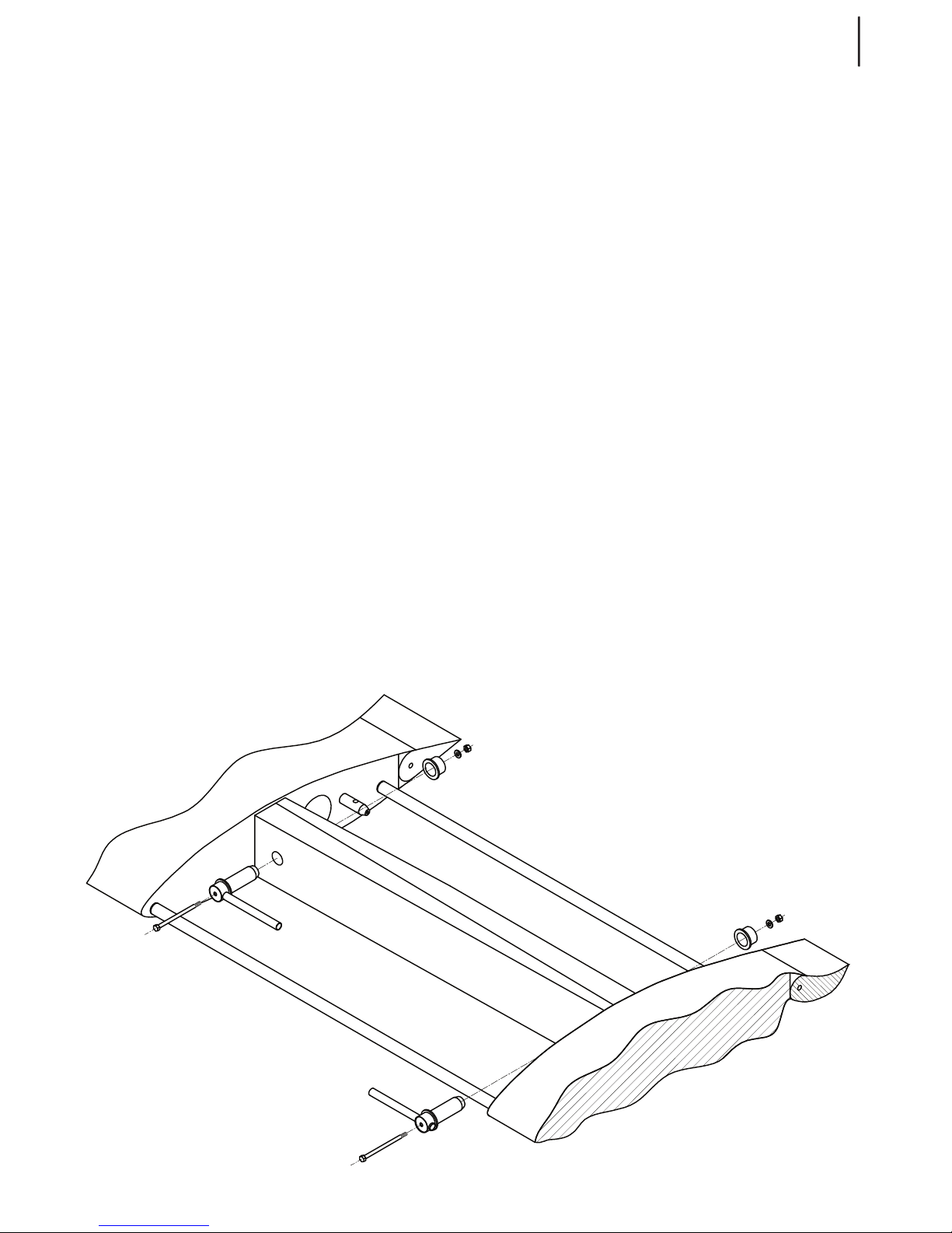
Assembling the wings
Three people (or two with a stand) are needed
to assemble the wings to the fuselage.
First block all three wheels for the fuselage to
stay in position.
Clean and grease the main wing pins and insertion openings. Open the canopy. Inside the
cockpit set the flap handle to neutral position
and unlock the spoilers’ handle. Make sure
you have all bolts, nuts, washers and spanners
needed within reach of a hand.
Lift one wing-half (one person at each end)
and bring it closer to the fuselage. While the
two are holding the wing-half high up, the
third person directs their movement to put the
wing’s main spar into the opening on the adjacent side of the fuselage.
Now push the wing-half into its final position
slowly. The person closest to the fuselage must
make sure the spoiler and flap connectors have
fitted into adequate fuselage fittings properly. At the same time, the person holding the
wingtip must start with slight circular movements (1cm each direction) in order to assure a
tight fit of the wing and its adequate bushings.
As this is done the person at the wingtip must
remain in positon holding the wing, whereas
the other two move over to the other winghalf, lift it and bring it closer to the fuselage.
Do not forget to make sure the spoiler and flap
connectors have fitted into adequate fittings
properly on this wing-half as well.
Both wing-halfs should now be in their final
position but still being held at wingtips. The
person not holding the wings must now insert
both pre-greased spar pins. First insert the pin
on the right-hand side of the cockpit because
of easier insersion (thinner spar infront), then
the pin on the lefe-hand side of the cockpit.
If necessary, the two at the wingtips can assist
by rocking the wings a couple of
millimeters up and down.
Only when both spar pins have been inserted
and secured, wingtips may be released.
Now check all control deflections as well as
flap and spoilers’ extensions for smooth,
unobstructed movement.
Insert all bolts and pins and secure them with
self-locking nuts. Do not forget to put aluminium washers underneath the nuts!
Connect all electical clables and fuel hoses to
their correct fittings.
Finally tape the gap between the fuselage and
the wing using self-adhesive tape.
31
TAURUS ELECTRO
www.pipistrel.si
Three people again are needed to disassemble
the wings.
First block all three wheels for the fuselage to
stay in position.
Disassemble the horizontal tail surfaces, disconnect all eventual electrical cables, then unscrew and remove both pin bolts.
WARNING! Do not remove spar pins yet!
Two people must now lift the wingtips (one
wingtip each) and the person in the cockpit remove the main spar pins, one by one,
smoothly.
Forcing pins out of their position may result
in structural damage, therefore the wingtip
holders must hold the wing-halfs precisely at
certain height!
Using slight circular movement at the wingtip,
the wing-halfs must now be pulled out of the
fuselage slowly. On pulling, each wing-half
must be held by two, one at the wingtip and
one near the spar.
As the wing-halfs have been pulled out, place
them onto a soft surface to prevent their
damage.
Schematic of wing (dis)assembly
Disassembling the wings
32
TAURUS ELECTRO
www.pipistrel.si
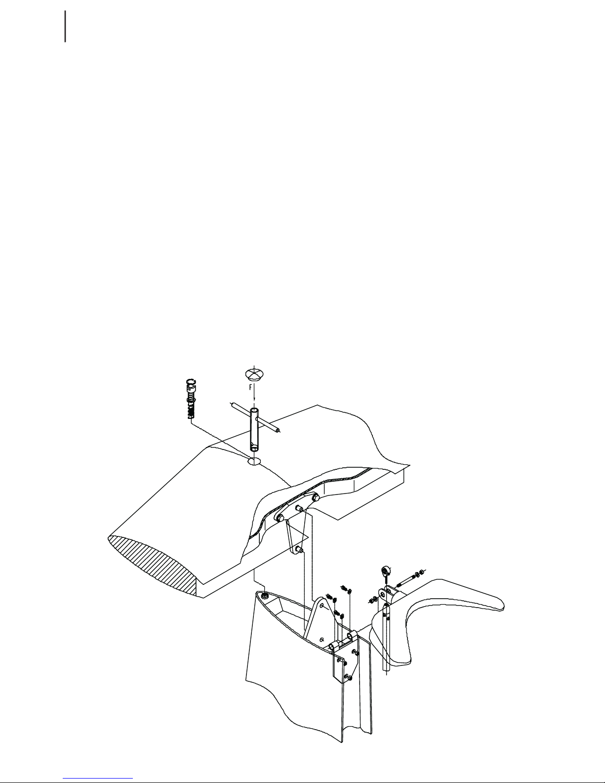
Set the trim handle to full forward position and remove the safety sticker covering the hole on top of
the horizontal stabilizer and the tape covering the gab between horizontal and vertical tail surfaces.
Now use the enclosed “T” key to push the safety pin screw down while spinning it counter-clockwise
until it is completely loose. To detach the horizontal tail unit push it forward using firm palm strokes
until the unit pops out.
When detached, always place the horizontal tail unit onto a soft surface to prevent damage.
Fitting the horizontal tail surfaces
Horizontal stabilizer and elevator MUST be united during the following procedure. To fit the horizontal tail surfaces first set the trim handle inside the cockpit to full forward position. Make sure the pins,
their holes and bushings have been cleaned and greased!
Lift the joint stabilizer and elevator and slide them into position by pushing them backwards. Now
use the enclosed “T” key to push the security screw down while spinning it clockwise until the screw
is completely tightened. Pull the “T” key out and make sure the safety pin holds the head of the
screw, so that eventual unscrewing will not occur.
At the end tape the gap between horizontal and vertical tail surfaces and cover the hole on top of
the vertical stabilizer with a sticker. Check control deflections for smooth, unobstructed movement.
Detaching the horizontal tail surfaces
Schematic of horizontal tail surfaces (dis)assembly

33
TAURUS ELECTRO
www.pipistrel.si
Bring the rudder close to fuselage and fit it first onto the top and then to the bottom hinge.
The rudder must then be fully deflected to one side to provide access to the rudder bolts. Use a selfsecuring, pre-glued M6 nut together with a washer and gently screw them onto the bolt using size
10 spanner. To reach the other rudder bolt deflect the rudder to the opposite direction and repeat
the up-stated procedure.
With both nuts tightened check full rudder deflections for smooth, unobstructed movement.
Detaching the rudder
Deflect the rudder to one side fully and unscrew the nut of the bolt with which the rudder is attached to the bottom hinge. This is the bolt located in-between the central bolt (axis of rotation) and
the bolt holding the metal ropes. DO NOT touch these two bolts - unscrew the nut of the middle bolt
ONLY. Now deflect the rudder to the opposite direction and repeat the up-stated procedure.
After both bolts have been unscrewed, lift the rudder and detach it first from the bottom, then from
the top hinge.
Schematic of rudder (dis)assembly
Attaching the rudder
34
TAURUS ELECTRO
www.pipistrel.si
Daily check-up
The daily check-up matches the preflight check-up.
Preflight check-up
WARNING! EVERY SINGLE CHECKUP MENTIONED IN THIS CHAPTER MUST BE PER
FORMED PRIOR TO EVERY FLIGHT, REGARDLESS OF WHEN THE PREVIOUS FLIGHT TOOK PLACE!
THE PERSON RESPONSIBLE FOR THE PREFLIGHT CHECKUP IS THE PILOT FROM
WHOM IT IS REQUIRED TO PERFORM THE CHECKUP IN THE UTMOST THOROUGH
AND PRECISE MANNER.
PROVIDED THE STATUS OF ANY OF THE PARTS AND/OR OPERATIONS DOES NOT COMPLY WITH
CONDITIONS STATED IN THIS CHAPTER, THE DAMAGE MUST BE REPAIRED PRIOR TO MOTOR
STARTUP. DISOBEYING THIS INSTRUCTIONS MAY RESULT IN SERIOUS FURTHER DAMAGE TO
THE PLANE AND CREW, INCLUDING INJURY AND LOSS OF LIFE!
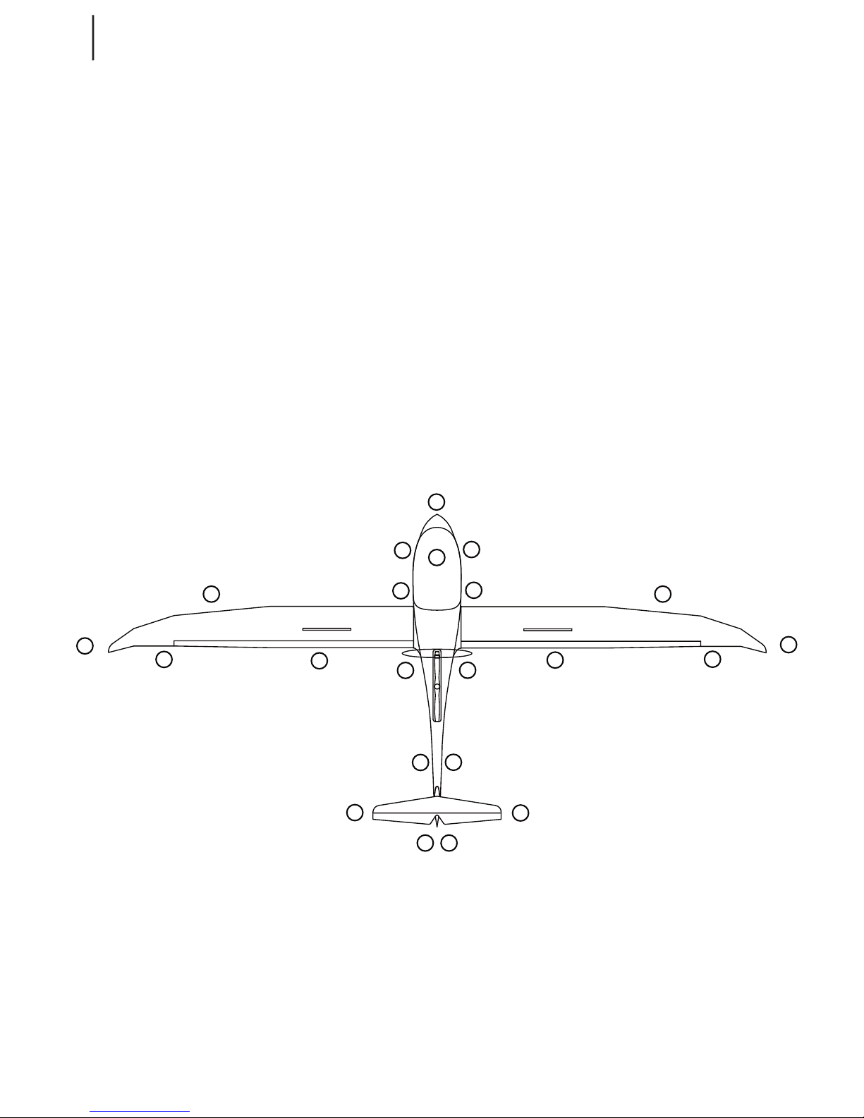
Schematic of preflight check-up
12
1
2
3
4
5
6
7
8
9
10
11
13
14
15
16
17
18
19
20
21
22
1 Glass cannopy 8 Right wing - trailing edge 15 Hor. tail surfaces (left)
2 LH flank 9 Right airbrake 16 Fuselage, continued (left)
3 Nose tip 10 Motor, propeller (RH side) 17 Motor, propeller (LH side)
4 RH flank 11 Fuselage, continued (right) 18 Left spoiler
5 Undercarriage, RH wheel 12 Hor. tail surfaces (right) 19 Left wing - trailing edge
6 Right wing - leading edge 13 Vert. tail surfaces (right) 20 Left wingtip
7 Right wingtip 14 Vert. tail surfaces (left) 21 Left wing - leading edge
22 Undercarriage, LH wheel
35
TAURUS ELECTRO
www.pipistrel.si
Glass cannopy
Surface condition: clear, no cracks, no wavy patterns, impact spots
Attachment fork: perfect closure, no deformations
De-fogging frame holes: clear for adequate airflow
Locking levers: check for correct and smooth operation, locking pin and bushing clean and greased
Water ballast reservoir: inserted and filled-up as required
LH flank
Surface condition: clear, no cracks, no wavy patterns, impact spots
Fuselage - cannopy frame joint: equal spacing, perfect closure
Nose tip
Pitot tube: firmly attached, no mechanical damage or bendings. Remove protection cover and make
sure it is not blocked or full of water.
Ventilation ring: firmly attached
Fuselage - cannopy frame joint: equal spacing, perfect closure
RH flank
Surface condition: clear, no cracks, no wavy patterns, impact spots
Fuselage - cannopy frame joint: equal spacing, perfect closure
Undercarriage, wheels
Bolts: fastened
Wheel: no mechanical damage (e.g. cracks), clean
Wheel axis and nut: fastened
Oil line (hydraulic brakes): no mechanical damage and/or leakage
Tyre: no cracks, adequate pressure
Wheel fairing: undamaged, firmly attached, clean (e.g. no mud or grass on the inside)
Wheel-bay doors: undamaged, check rubber-rope tension
Retraction mechanism: no visible abnormalities, adequate grease on sliding parts, clean of larger
particles e.g. soil, dirt.
Gear bay: free of larger particles, soil, dirt etc.
Under-belly drain holes: make sure they are not blocked and clean accordingly.
Wings’ leading edge
Surface condition: pristine, no cracks, impact spots, no paint and/or edge separations
Wing drain holes: make sure they are not blocked and clean accordingly.
Wingtip
Surface condition: pristine, no cracks, impact spots or bumps, no paint separations
1
2
3
4
5
6
22
21
7
20

36
TAURUS ELECTRO
www.pipistrel.si
Wings’ trailing edge
Surface condition: pristine, no cracks, impact spots, no paint and/or edge separations
Sealing tape between wing and aileron: undamaged and in position
Aileron: pristine surface, no cracks and/or impact spots, no paint abnormalities and edge separa-
tions, no vertical or horizontal free play, smooth and unobstructed deflections
Airbrakes
Airbrake: firm, smooth, equal and unobstructed extension, tightly fitted when retracted, springs stiff
and intact.
Motor, propeller, rescue parachute hood
Check for smooth propeller rotation, check for motor axle free play. No free play is permitted.
Check for any water or condensation inside the motor compartment, remove it accordingly.
Check battery boxes, connectors (all connected firmly) and exposed wiring.
Check the battery boxes behind the cockpit as well.
Propeller must be clean and undamaged.
Parachute rescue system cover: intact and firmly in place. No deformations whatsoever.
Fuselage, continued
Under-belly drain holes: make sure they are not blocked and clean accordingly
Vertical fin bottom part: no cracks, impact spots or paint separations along main chord
Surface condition: pristine, no cracks, impact spots or bumps, no paint and/or edge separations
Horizontal tail surfaces
Surface condition: pristine, no cracks, impact spots or bumps, no paint and/or edge separations
Hinges: no free play in any direction
Central securing screw on top or the horizontal stabilizer: fastened and secured
Self-adhesive tape covering the gap between horizontal and vertical tail surfaces: in position
Elevator: smooth and unobstructed up-down movement, no side-to-side free play
Vertical tail surfaces
Vertical fin bottom part: no cracks, impact spots or paint separations along main chord
Surface condition: pristine, no cracks, impact spots or bumps, no paint separations
Hinges: no free play in any direction
Rudder metal rope endings: intact, bolts in position
Tail wheel
Shock absorbing rubber: no cracks, firm and clean, check for no deformations
Tire: no cracks, adequate pressure
Wheel fork, fork base and bolt: nut tightened, no abnormalities, bearing in position, bolt attached,
straight and fastened
Lift the tail high enough so that the tail wheel is not touching the ground and make sure the
wheel side-to-side deflections are smooth and unobstructed
CAUTION! Preflight check-up should be performed following stations 1 through 22!
8
19
9
18
10
17
11
16
12
15
13
14

37
TAURUS ELECTRO
www.pipistrel.si
In-cockpit preflight check-up
Instrument panel and instruments: checked, Fuses: pushed in position
Master switch OFF (key in full left position): no control lights and/or electronic instrument activity
Master switch ON (key in full right position): control lights and electronic instrument active
Make sure you have set all instruments to correct initial setting.
Water ballast reservoir (front-cabin): check for water quantity and make sure it is appropriate for
your planned flight. Remove or ad water as necessary to keep the c.g. within limits.
WARNING! CHECK THE WATER BALANCE RESERVOIR IN FRONTCABIN AND VERIFY
CREW’S WEIGHT BEFORE EVERY FLIGHT AS IT MAY INFLUENCE THE CENTRE OF GRAVITY OF
AIRCRAFT TO THE POINT WHERE IT IS NO LONGER CONTROLLABLE!
Main wing spars and connectors: no visible abnormalities of metal parts, spars, pins and bolts; all
bolts and nuts in position and tightened
Electrical cables: correctly connected and in position
Seat belts: undamaged, verify unobstructed harness opening; fastening points intact
Glass cannopy: perfect closing at all points, smooth opening, hinges firmly attached; glass immacu-
lately clean with no cracks.
Flap handle: button spring firm, locking mechanism working properly, smooth movement along full
deflections, no free play or visible damage.
Spoilers (Airbrakes) handle: full forward and locked
Ventilation lever: as required
Radio wiring: test the switches, check connectors and headset, perform radio check
Battery: firmly in position, fittings clean with wires connected
Cockpit mirror: in position and adjusted
Emergency parachute release handle: safety pin removed. Make sure unobstructed access is
provided.
Adjust the rudder pedals according to your required legroom. Sit inside the cockpit and release the
pressure o the pedals. Pull the black knob in front of the control stick to bring the pedals closer to
you. To move the pedals further away, rst release the pressure of the pedals, then pull on the knob
slightly (this will release the lock in the mechanism). Now push the pedals forward using with your
feet, while keeping the black adjusment knob in your hand.

38
TAURUS ELECTRO
www.pipistrel.si
Normal procedures
and recommended speeds
To enter the cabin first unlock the cannopy frame and lift the glass canopy all the way by lifting the
lock levers or lifting pads on each side of the cabin. Sit onto the cabin’s edge and support your body
by placing hands onto this same cabin edge and middle cockpit console. Drag yourself into the seat
lifting first the inner and then the outer leg over the control stick. Immediately after having sat into
the seat, check rudder pedals’ position to suit your size and needs. Bring the pedals closer or further
away by pulling the handle behing the control stick and slide them to the desired position.
To lower the canopy gently hold and pull the metal levers on the side of the cocpit. To lock the cannopy once closed, push the levers forward so that they become parallel to the surface of the glass
frame. Verify that the cannopy is closed by applying upward-pressuse to the cannopy.
Fasten the safety harnesses according to your size.
WARNING! THE SAFETY HARNESS MUST HOLD YOU IN YOUR SEAT SECURELY. THIS IS ES
PECIALLY IMPORTANT WHEN FLYING IN ROUGH AIR, AS OTHERWISE YOU MAY BUMP INTO THE
CANOPY OVERHEAD.
Motor start-up
Before motor start-up
CAUTION! TO ENSURE PROPER AND SAFE USE OF AIRCRAFT IT IS ESSENTIAL FOR ONE TO
FAMILIARISE WITH MOTOR’S LIMITATIONS AND MOTOR MANUFACTURER’S SAFETY WARN
INGS. BEFORE MOTOR STARTUP MAKE SURE THE AREA AROUND THE PROPELLER IS CLEAR.
YOU CAN ALSO CHECK THIS IN THE INSTRUMENT PANEL MIRROR. IT IS RECOMMENDED TO
STARTUP THE MOTOR WITH AIRCRAFT’S NOSE POINTING AGAINST THE WIND.
Make sure the battery charge status will suffice for the planned flight duration.
Make sure the pitot tube is not covered and rescue parachute safety pin removed.
Engage wheel brakes. Hold the control stick in full aft position always when on the ground.
CAUTION! SHOULD YOU NOT BE HOLDING THE CONTROL STICK IN FULL AFT POSITION,
YOU MAY TIP THE NOSE OF THE AIRCRAFT AS THE CENTRE OF PROPULSION IS HIGH ABOVE
THE FUSELAGE.
Motor start
Make sure the master switch is in ON position (key full right).
Extend the propulsion unit (master-on-board-computer: right switch to UP position).
After the propustion unit is extended (indication green), set system enable ON (left switch ON).
The motor is now engaged and the propeller should be stationary in its vertical position. Verify this
in the miror.
CAUTION! THE RPM KNOB IS SENSITIVE, BE CAREFULL WHEN ROTATING IT.
Motor warm-up procedure
The motor does not require any warm-up procedure.

39
TAURUS ELECTRO
www.pipistrel.si
Taxi
Taxing technique does not differ from other taildragging aircrafts. Prior to taxiing it is essential to
check wheel brakes for proper braking action.
CAUTION! TAXI AT AT MOST 10KM/H / 5 KTS, AS THERE ARE NO DIFFERENTIAL BRAKES
AVAILABLE. STEERING IS PROVIDED BY A STEARABLE TAIL WHEEL THROUGH RUDDER INPUT.
Holding point
Make sure the temperatures, particulary battery system temperature is within operational limits.
Make sure the safety harnesses are fastened and canopy closed and secured at both sides.
Set flaps to T position. Power idle.
CAUTION! SHOULD THE MOTOR START TO OVERHEAT BECAUSE OF LONG TAXI AND HOLD
ING, SHUT DOWN THE MOTOR AND WAIT FOR THE MOTOR TEMPERATURES DROP TO REASON
ABLE VALUES. IF POSSIBLE, POINT THE AIRCRAFT’S NOSE TOWARDS THE WIND. THIS WILL PRO
VIDE COOLING MEANS WITH AIRFLOW TO COOL DOWN THE MOTOR FASTER.
Take-off and initial climb
Before lining-up verify the following:
Spoilers: retracted and secured
Battery charge status and health: sufficient and OK
Safety belts: fastened
Cabin: closed securely
Trim handle: in neutral position or slightly backward
Flap handle: T position
Runway:
clear
Now pull the stick to full aft position, line up and add full power.
Verify motor for sufficient RPM at full power.
CAUTION! KEEP ADDING POWER GRADUALLY.
WARNING! SHOULD MOTOR RPM NOT REACH SUFFICIENT RPM WHEN AT FULL THROT
TLE, ABORT TAKEOFF IMMEDIATELY, COME TO A STANDSTILL AND VERIFY THE PROPUSTION
UNIT.
Start the takeoff roll pulling the elevator full aft, then slowly ease on the sitck the lift the tail wheel of
the ground as you accelerate. Reaching Vr (between 70 -75 km/h; 38-42 kts), pull on the stick to get
the aircraft airborne.
CAUTION! CROSSWIND MAX 28 KM/H 15 KTS TAKEOFF SHOULD BE PERFORMED WITH
AILERONS DEFLECTED OPPOSITE THE DIRECTION OF THE WIND. SPECIAL ATTENTION SHOULD
BE PAID TO MAINTAINING RUNWAY HEADING AND NOT LOWERING THE WINGTIP TOO MUCH!

40
TAURUS ELECTRO
www.pipistrel.si
Climb
When airborne, accelerate at full power. As you reach 90 km/h (52kts) at a height above 50 meters
(165 ft), retract flaps to neutral position. and retract the landing gear. Reduce power to 30 kW.
WARNING! ALWAYS MOVE THE LANDING GEAR COCKPIT HANDLE STRONGLY, WITHOUT
HESITATION AND WITH ONE SINGLE CONTINUOUS MOVEMENT TOWARDS THE DESIRED
POSITION.
Adjust the trim to neutralise the stick force if necessary.
Remember to keep the temperatures and RPM within operational limits during this manoeuvre.
WARNING! FULL POWER CAN BE UTILISED FOR A MAXIMUM 1 MINUTE. AFTER THIS, RE
DUCE POWER TO 30 KW AND VERIFY THIS WITH ESYSMAN.
Level flight
Taurus Electro is not desinged to be a cruising aircraft, however you may be able to maintain level
cruise flight should this be required. To cover distances, saw-tooth flight with interchanging climbs
and glides are an established common practice. When saw-toothing, plan your flight well and always
restart the motor over a landable terrain.
Flights in rough atmosphere
Should you experience turbulence, reduce airspeed and continue flying with flaps set to neutral
position.
CAUTION! IN ROUGH AIR EXTEND AIRBRAKES UNPOWERED FLIGHT FOR SHORT TIME IF
NECESSARY TO KEEP AIRSPEED BELOW VRA.
Descent and final approach
Landing the Taurus Electro with the motor out should be strongly avoided due stress on the propeller mast. It will decrease the life-time of critical component as well. Therefore it is recommended
that you conduct the approach and landing like a glider - with the propulsion unit in its retracted
(DOWN) position.
On downwind (150-200 m, 500-700 ft), maintain a speed of 100 km/h (55 kts) and lower and secure
the landing gear. Before turning base, set the flaps to T stage, and reduce your speed to 90-95 km/h
(48-51 kts). Set trim to neutralise stick force if necessary.
CAUTION! WHEN DESCENDING, MAKE SURE THE PROPULSION UNIT IS RETRACTED.
CAUTION! WITH FLAPS IN L POSITION ONLY HALF WAY AILERON DEFLECTIONS ARE
PERMITTED.
On final, set flaps to L position only if the runway is very short and a steep angle of arrival is
required. Align with the runway and extend airbrakes while maintaining an airspeed of 90-95 km/h
(48-51 kts). Use airbrakes to control your approach glide path.
CAUTION! CROSSWIND LANDINGS REQUIRE HIGHER FINAL APPROACH SPEEDS TO ENSURE
AIRCRAFT’S SAFE MANOEUVRABILITY.

41
TAURUS ELECTRO
www.pipistrel.si
Roundout and touchdown
CAUTION! See chapter “Performance” for landing performance.
Final roundout (flare) and touchdown should be performed at following airspeeds:
Calm air, aircraft at MTOM 75 km/h (40 kts) IAS
Rough air, aircraft at MTOM (incl. strong crosswinds up to 28 km/h
(15 kts)) 78 km/h (42 kts) IAS
CAUTION! LAND THE AIRCRAFT IN SUCH A MANNER THAT ALL THREE WHEELS TOUCH THE
GROUND AT EXACTLY THE SAME TIME. WHEN TOUCHING DOWN, RUDDER MUST NOT BE DE
FLECTED IN ANY DIRECTION RUDDER PEDALS CENTRED.
When on ground, start braking action holding the control stick in full back position. Stear the aircraft
by using rudder inputs. Provided the runway length is sufficient, come to a complete standstill without engaging the brakes to ensure their long life.
WARNING! AFTER TOUCHDOWN, DO NOT RETRACT SPOILERS IMMEDIATELY, AS THIS
CAUSES SUDDEN LIFT INCREASE AND THE AIRCRAFT MAY REBOUND OFF THE GROUND.
SHOULD THIS OCCUR, HOLD THE ELEVATOR STEADY; UNDER NO CIRCUMSTANCES ATTEMPT
TO FOLLOW AIRCRAFT’S MOVEMENT WITH ELEVATOR DEFLECTIONS, SINCE TAURUS ELECTRO
TENDS TO ATTENUATE REBOUNDING BY ITSELF. HOWEVER, IT IS IMPORTANT TO MAINTAIN
RUNWAY HEADING USING THE RUDDER AT ALL TIMES. TO PREVENT THIS, RETRACT SPOILERS
ONLY AFTER THE AIRCRAFT HAS COME TO A COMPLETE STANDSTILL.
WARNING! TOUCH AND GOES ARE NOT POSSIBLE!
Having reached a complete standstill, extend the motor (Motor start-up) and taxi (Taxi) off the runway.
Crosswind approach and roundout
CAUTION! CROSSWINDS PROLONG LANDING RUNWAY LENGTH SEE CHAPTER
“PERFORMANCE”.
Performing a crosswind landing, the wing-low method should be used. When using the wing-low
method it is necessary to gradually increase the deflection of the rudder and aileron to maintain the
proper amount of drift correction.
WARNING! IF BY CHANCE THE CRAB METHOD OF DRIFT CORRECTION HAS BEEN USED
THROUGHOUT THE FINAL APPROACH AND ROUNDOUT, THE CRAB MUST BE REMOVED THE
INSTANT BEFORE TOUCHDOWN, BY APPLYING RUDDER TO ALIGN THE AIRCRAFT’S LONGITU
DINAL AXIS WITH ITS DIRECTION OF MOVEMENT.

42
TAURUS ELECTRO
www.pipistrel.si
Parking
Come to a complete standstill by engaging brakes. Set the system enable switch OFF, then master
switch OFF. Unlock airbrakes (handle lifted slightly) and insert paracute rescue system handle’s safety
pin. Open the cannopy, unfasten safety belts and exit the cockpit. Close and lock the cannopy after
you have left the aircraft. When closing the canopy, make sure that the lock-handles are in OPEN position not to damage the locking pins. Also, block the wheels if parking on a slope.
CAUTION! WHENEVER YOU LEAVE THE AIRCRAFT MAKE SURE THE CANNOPY IS CLOSED
AND LOCKED. SHOULD YOU FORGET TO DO THIS THE CANNOPY FRAME MAY NOT FIT THE FU
SELAGE FRAME ANY MORE WHEN YOU RETURN, SINCE THE STRETCH COEFFICIENT OF FIBRE
GLASS AND PLEXIGLASS ARE SIGNIFICANTLY DIFFERENT. ALSO, COVER THE CANNOPY WITH A
FABRIC COVER, TO PREVENT THE CABIN FROM OVERHEATING PROTECTOIN TO INSTRUMENTS
AND SYSTEMS.
Retracting & Extending propulsion unit in flight
This procedure applies only for retracting/extending the propulsion unit as an intentional event, be
aware you may lose up to 100m (300ft) of altitude during this procedure.
If under power, set rpm to minimum (rotate knob left) and select engine DOWN. Reduce speed to 80
km/h (43 kts) and set flaps to 1st stage. Continue decellerating towards 70 km/h (40 kts).
The system will complete the retraction/extension by itself. Once retracted (confirmed by green
LED status light), select System enable OFF. For more details please consult the ESYS-MAN section in
chapter Aircraft and Systems on board in this manual.
To restart the motor in-flight follow the same procedure as for Motor startup (page 34) while maintaing level flight at 80 km/h (43 kts) with flaps in 1st stage.
WARNING! ALWAYS WAIT BEFORE THE SYSTEM CONFIRMED IN FULL EXTENDED OR FULL
RETRACTED POSITION BEFORE OPERATING THE MASTER SWITCH OR THE SYSTEM ENABLE
SWITCH! THE PROPELLER BRAKE IS ELECTRIC AND DOES NOT WORK WITHOUT POWER IN
FLIGHT AND WITH THE SYSTEM IN THE MIDDLE OF RETRACTION, CUTTING THE POWER WILL
RESULT IN PROPELLER DAMAGE!
WARNING! BEFORE YOU ENABLE THE MOTOR, MAKE SURE THE PROPELLER IS IN
THE FULLY EXTENDED AND UPRIGHT POSITION GREEN LIGHT INDICATION!
Should the batteries cool down during unpowered flight, use up to 1000 RPM until the battery temperature recovers to operating range.
CAUTION! DO NOT ADD FULL POWER WHILE THE BATTERIES ARE STILL COLD. KEEP FLYING
AT 80 KM/H 43 KTS WITH FLAPS IN L STAGE AND NOT MORE THAN 1000 RPM TO WARMUP
THE BATTERIES FIRST IF COLDER THAN 5°C.
NOTE: IT IS NOT REQUIRED TO COOL DOWN THE SYSTEM BEFORE RETRACTION.
43
TAURUS ELECTRO
www.pipistrel.si
Introduction
Airspeed indicator
calibration
Take-off performance
Climb performance
Cruise
Descent
Landing performance
Maneuver & gust
envelope
Speed polar
Additional technical data
Performance

TAURUS ELECTRO
www.pipistrel.si
Introduction
This chapter provides information on aircraft’s airspeed calibration, stall speeds and general performance. All data published was obtained from test flight analysis. Test pilots were instructed to
control the plane simulating average pilot’s flying skills.
Airspeed indicator calibration (IAS to CAS)
Pitot tube’s ingenious mounting and construction makes IAS to CAS correction values insignificant.
Therefore pilots should regard IAS to be same as CAS. IAS = CAS.
Stall speeds
Stall speeds at MTOM are as follows:
flaps in negative position; -5° (up): 75 km/h (40.5 kts)
flaps in neutral position; 0° (neutral): 71 km/h (38.3 kts)
flaps in 1st position; +5° (down): 68 km/h (36.7 kts)
flaps in T position; +9° (down): 65 km/h (35.0 kts)
flaps in L position: +18° (down): 63 km/h (34,0 kts)
Take-off performance
All data published in this section was obtained under following conditions:
aircraft at MTOM
runway elevation: 100 meters (330 feet)
wind: calm
runway: dry grass runway with low-cut grass, no significant up- or downslope
ICAO standard atmosphere
Taurus Electro
takeoff runway length at MTOM
160 m (530 ft)
takeoff runway length (over 15m (50 ft) obstacle) 245 m (800 ft)
Note: in order to meet the data for takeoff runway lenght over 15 m obstacle maintain Vx
after take-off.
Takeoff runway length may vary depending on the wind, temperature, elevation and
wing & propeller surface condition.

45
TAURUS ELECTRO
www.pipistrel.si
Effect of elevation
The table below provides data about the effect of elevation on takeoff runway length.
elevation (m) 0 500 1000 1500
atmosph. pressure (hPa)
1012 954 898 845
outside temperature (°C)
15.0 11.7 8.5 5.2
Takeoff runway length [m
(ft)]
Electro
160 (530) 185 (610) 232 (765) 275 (910)
WARNING: If the outside temperature is higher than the standard value it is mandatory to
consider the takeoff runway length prolongs as follows:
L = 1,10 • (Lh + Lt - L0).
Abbreviations are as follows:
Lh = takeoff runway length at present elevation,
Lt = takeoff runway length at sea level at same atmospheric conditions,
L0 = takeoff runway length at 15°C.
The graph below indicates how takeoff runway length changes as altitude increases.
Effect of the wind
Wind (head, cross or downwind - also called tailwind) affects aircraft’s ground speed (GS).
Headwind on takeoff and landing causes the Takeoff and Landing runway length to shorten as the
GS is smaller during these two flight stages. The opposite stands for tailwind on takeoff and landing
as tailwind prolongs Takeoff and Landing runway length significantly.
The data on the next page was obtained through testing and therefore serve as informative values
only.
Headwind shortens Takeoff and Landing runway length by 8 meters (25 feet) with every 5 km/h
(3 kts) of wind increase (e.g. provided there is a 10 km/h (6 kts) headwind on takeoff and landing, dis-
tances will be approximately 16 meters (50 feet) shorter then ones published in the manual).
150 500
200 650
250 820
takeoff runway length
elevation (m)
elevation (ft)
650
1300
2000
2600
3200
4000
4600
m f
t
0
200 400
600 800 1000 1200
1400

46
TAURUS ELECTRO
www.pipistrel.si
Tailwind prolongs Takeoff and Landing runway length by 18-20 meters (60-65 feet) with every 5
km/h (3kts) wind increase (e.g. provided there is a 10 km/h (6kts) tailwind on takeoff and landing, distances will be approximately 36-40 meters (120-130 feet) longer then ones published in the manual).
3x
WARNING! TAILWIND AFFECTS TAKEOFF AND LANDING PERFORMANCE BY MORE THAN
TWICE AS MUCH AS HEADWIND DOES.
The table below provides data about the effect of headwind (+) and tailwind (-) on takeoff runway
length.
windspeed (m/s) -3 -2 -1 0 2 4 6
windspeed (kts) -6 -4 -2 0 4 8 12
Takeoff runway length [m (ft)]
Electro
297 (975) 243 (800) 205 (670) 160 (520) 154 (505) 147 (480) 122 (400)
The graph below indicates how takeoff runway length changes when affected by wind.
Effect of outside temperature
The table below provides data about the effect of outside temperature on takeoff runway length.
temperature (°C) 13 20 25 30 35
Takeoff runway length [m (ft)]
Electro
180 (590) 197 (645) 215 (705) 237 (780) 255 (836)
50 160
150 500
200 650
100 330
250 820
m
ft
0
-4
0
4
8
12
16
-8
kts
takeoff runway length
m/s
-4 -2
0
2
4
6
8

47
TAURUS ELECTRO
www.pipistrel.si
The graph below shows how takeoff runway length changes when affected by temperature chances.
Climb performance
Taurus Electro
best climb speed Vy 100 km/h
(54 kts)
best climb rate at MTOM 2.9 m/s (580 fpm)
Effect of elevation
The table below provides data about the effect of elevation on climb rate at best climb speed Vy.
Taurus Electro
0 m (0 ft) 3.1 m/s (620 fpm)
500 m (1600 ft) 2.9 m/s (580 fpm)
1000 m (3300 ft) 2.7 m/s (540 fpm)
1500 m (5000 ft) 2.5 m/s (500 fpm)
The graph below indicates how climb rate changes as altitude increases.
outside temperature (°C)
5
10
15
20
25
30
35
0
50 160
150 500
200 650
100 330
250 820
m f
t
takeoff runway length
0
m/s fpm
650
1300
2000
2600
3300
4000
4600
m
ft
4 800
2 400
climb rate
200
400 600 800
1000
1200 1400
elevation

48
TAURUS ELECTRO
www.pipistrel.si
Descent
The rate of descent and glide path are adjusted using airbrakes (spoilers).
Typical sink rate, with flaps set to L position and spoilers fully extended, measures
4,5 m/s (900 fpm) at 90 km/h (48 kts) and 6,0 m/sec (1200 fpm) at 100 km/h (62 kts).
Taurus Electro
max. sink rate, spoilers extended, flaps at L and at flap speed limit
5.8 m/sec
(1160 fpm)
Landing performance
PRECISE DATA WILL BE PUBLISED AFTER DEDICATED TEST FLIGHTS! PRESENT DATA IS
SUBJECT TO CHANGE WITHOUT NOTICE!!!
Landing length will vary depending on the elevation, gross weight, touchdown velocity, wind direction and how aggressive the braking action is. In following conditions: aircraft at MTOM, airport
elevation 100 meters
(300 feet), wind calm; the landing length measures 110 meters (330 feet). Should
you be flying solo, the length shortens by another 10 meters (30 feet).
WARNING! RUNWAY PROPORTIONS MUST BE IN EXCESS OF 400 X 30 METERS (1300 X 100
FEET) WITH NO OBSTACLES IN A 4° RANGE OFF RUNWAY HEADING IN ORDER ENSURE SAFE
FLYING ACTIVITY. USE OF SHORTER STRIPS SHOULD BE CONSIDERED A MAJOR EXCEPTION AND
SHOULD ONLY BE ATTEMTED BY EXPERIENCED PILOTS AND AT OWN RISK.
Crosswind landing limitations
Maximum allowed crosswind speed for landing with flaps in L position as well as take-off with flaps
in T position is 28 km/h (15 kts).
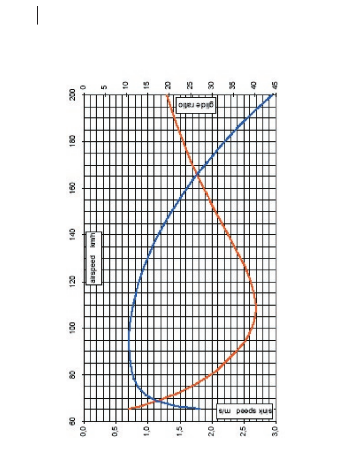
Gliding performance
The glide is defined as unpowered straight and level flight at a speed providing best lift over
drag ratio or minimum sink rate.
Should the motor become inoperative in flight, as a result of either intended or unintended action,
and it cannot be restarted, react as follows:
establish straight and level flight at the speed providing best lift over drag ratio, if you desire
to overcome greatest distance at reach from initial altitude.
establish straight and level flight at speed providing minimum sink rate, if you desire do stay
airborne the longest. This may come in handy in case you are forced to give way to other aircraft or if
you simply need time to determine the most appropriate site to land.
Taurus Electro
minimum sink speed 94 km/h (51 kts)
minimum sink rate (prop.unit., gear retracted) 0.70 m/s (140 fpm)
minumum sink rate(prop.unit extended.) 1.52 m/s (270 fpm)
best lift/drag ratio speed 108 km/h (58 kts)
best lift/drag ratio (prop.unit., gear retracted) 1:41
best lift/drag ratio (prop.unit extended.)
1:25
L/D ratio at 150 km/h
(80 kts) 1:32

49
TAURUS ELECTRO
www.pipistrel.si
Maneuver & gust envelope
manouever and gust
TAURUS 472,5kg flap 0
5,30
4,00
-1,50
-2,65
-2,04
4,81
-2,81
4,04
-4
-3
-2
-1
0
1
2
3
4
5
6
0 20 40 60 80 100 120 140 160 180 200 220 240 260 280 300
EAS km/h
load factor
manouever and gust
TAURUS 360kg flap 0
6,96
5,25
-1,97
-3,48
-2,68
5,61
4,68
-3,61
-4
-3
-2
-1
0
1
2
3
4
5
6
7
0 20 40 60 80 100 120 140 160 180 200 220 240 260 280 30
0
EAS km/h
load factor
50
TAURUS ELECTRO
www.pipistrel.si
Speed polar
(472 kg, prop.unit & landing gear retracted, optimal flap settings)

51
TAURUS ELECTRO
www.pipistrel.si
Additional technical data
Taurus Electro
stall speed (flaps extended) 63 km/h
(34.0 kts)
stall speed (flaps retracted)
71 km/h
(38.3 kts)
max. speed of spoiler extension 163 km/h (188 kts)
max. speed with flaps in +5° position 130 km/h (70 kts)
max. speed with flaps in T position 130 km/h (70 kts)
max. speed with flaps in L position 110 km/h (59 kts)
manoeuvring velocity Va 163 km/h (88 kts)
maximum rough air speed Vb (gusts 15 m/s) 163 km/h (88 kts)
max. speed with powerplant extended 120 km/h
(65 kts)
max. speed in tow (where permitted legally) 150 km/h (80 kts)
VNE 225 km/h (121 kts)
Vx - best climb-over-distance ratio speed 85 km/h (46 kts)
Vy - best climb rate speed 100 km/h (54 kts)
max. climb rate at MTOM 3.1 m/s (620 fpm)
minimum sink speed 94 km/h (51 kts)
minimum sink rate 0.70 m/s (140 fpm)
max. sink rate with spoilers extended 5.8 m/s (1160 fpm)
best glide ratio speed 108 km/h (58 kts)
takeoff runway length at MTOM 160 m (525 ft)
takeoff runway length at MTOM over 15 m obst. 245 m (800 ft)
best glide ratio 1:41
glide ratio at 150 km/h
1:32
45° left to 45° right - bank to bank time
3.5 s
battery capacity (standard configuration) 4.75 kWh
battery capacity (optional configuration) 7.10 kWh
useful battery capacity (recommended, standard) 3.8 kWh
useful battery capacity (recommended, optional) 5.7 kWh
max. wing load factors
+5.3 G -2.65 G
WARNING! Wing and propeller surfaces must be immaculately clean, dry and undamaged at
all times. As all airfoils are laminar any impact spots, bumps and even a dirty (incl. water, snow...)
surface may significantly lower flight performance. Stall speed, takeoff and landing runway
length, sink rates and energy consumption increase, while climb rates, ceiling, lift-over-drag ratio
and endurance decrease by as much as 30%. Please consult a Pipistrel representative for
high-altitude performance ratings.

52
TAURUS ELECTRO
www.pipistrel.si
This page is intentionally left blank.

53
TAURUS ELECTRO
www.pipistrel.si
Weight and balance
Introduction
Weighing and centre of
gravity calculation for
empty mass
Weight and Balance
report - including:
Useful load distribution
Definitions and
explanations

54
TAURUS ELECTRO
www.pipistrel.si
Weight and balance
Introduction
This section contains the payload range within which the aircraft may be safely operated.
Weighing procedure and procedure for calculating the in-flight c.g. are also provided.
Refer to equipment list for the installed equipment and accessories.
Weighing and c.g. calculation - empty mass
1. Completely assemble the aircraft, in closed space without any wind disturbance, and with:
- gear down
- motor, flaps and airbrakes retracted,
- control surfaces neutral,
- equipment and accessories in accordance with equipment list.
2. Remove all foreign objects, e.g. tools, maps, ...
3. Empty the water ballast tank, remove baggage.
4. Insert scales under main and a scale with support under tail wheel in order to level the
airplane as follows:
- the slope of upper and lower contour of fuselage tailcone in front of fin must be equal, check
with water scale,
- wings level.
5. Read scale readings, subtract eventual tare weight in order to get net weight.
NOTE: IF ACCURATE HIGH RANGE SCALES FOR MAIN WHEELS ARE NOT AVAILABLE, AIR
CRAFT EMPTY MASS MAY BEDETERMINED BY ADDING UP MASSES OF ALL COMPONETS: LEFT
HAND WING, RIGHTHAND WING, FUSELAGE, HORIZONTAL TAIL.
6. Measure distances »a« and »b« between verticals through axis of main wheels, tail wheel
and datum.
Use plumb line to mark verticals at the floor.
For main wheels and wing leading edges take average of Left-hand and Right-hand verticals.
NOTE: DISTANCES A AND B MAY CHANGE WITH AIRCRAFT WEIGHT DUE TO DEFLEC
TION OF LANDING GEAR THEY MUST BE MEASURED AT EACH WEIGHING.
7. Calculate c.g. of empty mass as follows:
X
CG.empty
= (G2.b) / G
empty
- a
G
empty
[kg] Empty mass (with equipment and accessories in accordance with equipment
list, but without occupant(s), baggage and water ballast).
G
2
[kg] Load on tailwheel.
X
CG.empty
[mm] Location of empty mass c.g., positive aft of datum.
a
[mm] Distance between main wheel axis and datum, positive for main wheel forward
of datum.
b
[mm] Distance between main and tail wheel axis, always positive.
Datum
Leading edge of wing root section..
55
TAURUS ELECTRO
www.pipistrel.si
Weight and balance
NOTE: WEIGHING AND C.G. CALCULATION OF FLIGHT MASS CAN BE DONE AS ABOVE, BUT
WITH THE FOLLOWING REMARKS:
FLIGHT MASS INCLUDES EMPTY MASS, OCCUPANTS, BAGGAGE AND WATER BALLAST.
RUDDER PEDALS AND SEATING POSITION MUST BE ADJUSTED AS IN FLIGHT.
However, flight mass and c.g. are normally calculated as shown in “Flight mass and c.g.”.
Weight and balance report
(including: Useful load distribution)
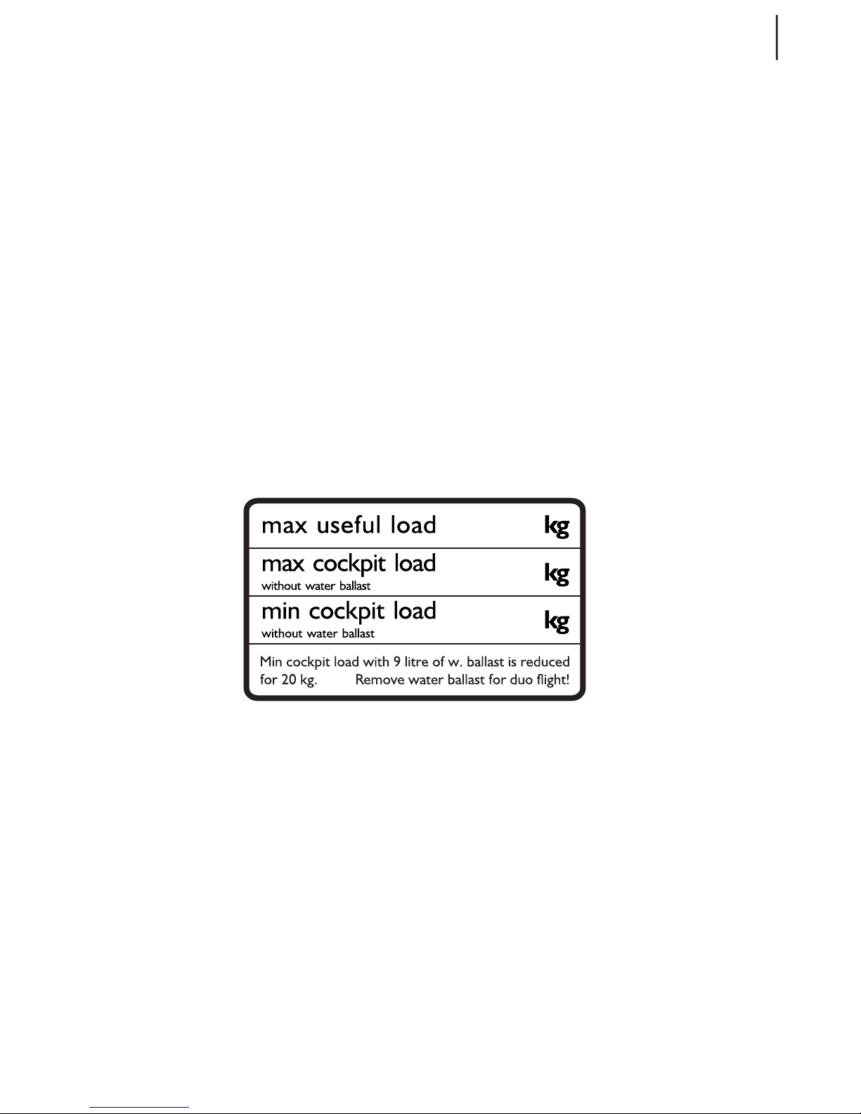
Fill-up »Weight and Balance« report on the next page.
“Empty mass c.g. limits” diagram is used to find out maximum and minimum cockpit load with
respect to mass and centre of gravity of empty aircraft.
Each weighing and centre of gravity calculation has to be entered in the »Weight and Balance«.
If minimum and maximum cockpit load change with respect to last weighing, cockpit placard must
be changed or corrected as well.
After installation or removal of equipment or accessories, repair, painting, or any change which
affects weight and balance, a new »Weight and Balance« (weighed or calculated, whatever is more
appropriate) must be accomplished.

56
TAURUS ELECTRO
www.pipistrel.si
Pipistrel d.o.o.
Ajdovš
čina
Weight and Balance -
Serial Number Registration
Weighing and C.G. calculation - empty mass
1
date of weighing /
1. example 2. example 3. example
2
acomplished by /
3
date of "Equipment list" /
4
main wheel Lh G
1 Lh
kg 123,0 123,4 122,0
5
main wheel Rh G
1 Rh
kg 124,4 124,8 123,5
6
main wheel total G
1
kg 247,4 248,2 245,5
7
tail wheel G
2
kg 49,6 48,8 47,5
8
distance a mm 22 24 23
9
distance b mm 4402 4406 4400
10
empty mass =(6+7) G
empty
kg 297,0 297,0 293,0
11
empty mass C.G. X
CG.empty
mm 713 700 690
12
max cockpit load
without w.ballast
(from "Empty mass c.g. lim its" diagram)
kg 180,0 175,5 169,0
Component
mass
kg kg kg kg
Lh wing
incl.flaperon
Rh wing
incl.flaperon
Fuselage -
complete
Horiz. tail
Empty mass
Empty mass is with equipment and accesories per equipment list, and without occupants, fuel, baggage and water ballast.
X
CG.empt
y
= (G2.b)/G
empt
y
- a
Useful load distribution
13
5,2745,2745,2745,2745,2745,2745,274gkssamxam
14
max useful load = (13-10) kg 175,5 175,5 179,5
15
max cockpit load
without w.ballast
(declared, see Notes)
kg
175,5
less fuel
less bagage
175
,5
less fuel
less bagage
169,0
16
min cockpit load
without w.ballast
(from "Empty mass c.g. lim its" diagram)
kg 86,0 82,0 78,0
17
Inspector
signature & stamp
/
Notes:
● Declared max cockpit load without water ballast is: 14 - fuel - baggage, if 14 is less than, or equal to, 12.
12, if 14 is more than 12.
● Water ballast is installed for solo flight with lightweight pilot for not to exceed aft c.g. limit.
Min cockpit load may be reduced for 2,3 kg per each litre of water ballast.
● If water ballast is left in the tank for duo flight, max cockpit load must be reduced for 2,3kg per each litre of water ballast.
● Influence of fuel and baggage on aircraft c.g. (and corresponding cockpit load) is neglectable.
● Max mass of single occupant (due to structural load per seat) is 110kg.
● Fuel [kg] = 0,76 kg/litre × litres.
a
X
cg
b
Weight and balance
TAURUS ELECTRO

57
TAURUS ELECTRO
www.pipistrel.si
Definitions and explanations
Empty mass and c.g.
Empty mass is mass of empty aircraft with equipment and accessories in accordance with equipment list. Refer to Weight and Balance report for actual value.
»Empty mass c.g. limits« diagram provides empty mass c.g. limits within which flight mass c.g. is kept
in limits. Or differently, the diagram is used to find out cockpit load with respect to mass and c.g. of
empty aircraft.
Minimum cockpit load is obtained as follows:
1. Locate c.g. of empty mass X
CG.empty
[mm] at the Left-hand vertical axis and draw a horizontal line
through it.
2. Locate empty mass G0 [kg] at the bottom horizontal axis and draw a vertical line through it.
3. The intersection of two lines drawn determines minimum cockpit load. Interpolate between lines
of constant minimum cockpit load (RED - 65, 70, 75 kg, ...), if necessary.
NOTE: MIN. COCKPIT LOAD MAY BE REDUCED FOR 2.3 KG PER EACH LITRE OF W. BALLAST.
Empty mass c.g. limits
Cockpit load in kg with respect to
mass and c.g. of empty aircraft
90
65
70
75
80
85
95
lines of constant
min cockpit load
- aft CG limits
lines of constant
max cockpit load
- front CG limits
140
15
0
16
0
17
0
18
0
19
0
20
0
55
60
540
55
0
56
0
57
0
58
0
59
0
60
0
61
0
62
0
63
0
64
0
65
0
66
0
67
0
68
0
69
0
70
0
71
0
72
0
73
0
74
0
75
0
76
0
77
0
78
0
79
0
80
0
81
0
82
0
83
0
84
0
28
0 282 284 286 288 290 292 294 296 298 300 302 304 306 308 310 312 314 316 318 320
empty mass kg
CG of empty mass -
distance aft of datum in mm .
Weight and balance

58
TAURUS ELECTRO
www.pipistrel.si
Maximum cockpit load is obtained as follows:
1. Intersection point from the previous step 3. determines maximum cockpit load with respect to
maximum permitted front c.g. of aircraft. Interpolate between lines of constant maximum cockpit
load (BLUE - 140, 150, 160 kg, ...), if necessary.
NOTES:
IF WATER BALLAST IS LEFT IN TANK FOR DUO FLIGHT, MAXIMUM COCKPIT LOAD MUST BE
REDUCED FOR 2.3 KG PER EACH LITRE OF WATER BALLAST.
MAXIMUM COCKPIT LOAD WITH RESPECT TO AIRCRAFT MAXIMUM MASS IS OBTAINED BY
SUBTRACTING EMPTY MASS, BAGGAGE AND WATER BALLAST FROM MAXIMUM MASS. DECLARED
MAXIMUM COCKPIT LOAD IS THE LOWEST OF TWO VALUES
Maximum mass
Maximum mass = 472.5 kg fot aircraft with parachute rescue system.
Useful load distribution
Useful load items are cockpit load, baggage, water ballast.
Cockpit load = occupants (pilot + passenger).
The sum of useful load items must not exceed max useful load.
Max useful load = max.mass - empty mass.
Aircraft flight mass and c.g. depend on quantity and distribution of useful load. Quantity and
distribution of useful load items are explained below. However, the influence of useful load items is
briefly expressed in the condition that, if for a given empty mass and c.g. the max useful, max and
min cockpit load from »Weight and Balance« or cockpit placard are respected, aircraft max mass
and in-flight c.g. will also be kept within limits. Refer to »Weight and Balance« or cockpit placard for
actual value of max useful load and its distribution.
Cockpit load
Refer to »Weight and Balance« or cockpit placard for max and min cockpit load.
Max mass of single occupant (due to structural load per seat) is 110 kg.
Baggage
Max baggage = 10kg.
Baggage quantity depends on useful load, cockpit load and water ballast. The sum of cockpit load,
baggage and water ballast must not exceed max useful load.
Baggage compartment behind the seat is close to aircraft c.g. – the influence on aircraft c.g. is
neglectable.
Water ballast
Water ballast in fuselage nose is installed for solo flight with lightweight pilot for not to exceed aft
c.g. limit. For duo flight it is normally removed, because it reduces useful and max cockpit load.
Max water ballast = 9 litre (9kg). Refer to the note of »Weight and Balance« or cockpit placard for
detailed instruction.
Weight and balance

59
TAURUS ELECTRO
www.pipistrel.si
Flight mass and c.g.
Flight mass is the sum of empty mass, cockpit load, baggage and water ballast. Flight mass c.g. calculation is done in a table as shown by example below:
- multiply mass by distance from datum (positive for items aft of datum) to get moment [kg.mm] of
each item,
- add up moments of all items,
- add up masses of all items,
- divide the sum of moments [kg.mm] by the sum of masses [kg] to obtain flight mass c.g. [mm].
Reference masses and c.g.’s of different items
masses and c.g.’s
of different items
mass distance from datum,
positive = aft
kg mm
pilot only -550
pilot + passenger -541
water ballast
max 9 -1800
baggage max 10 150
instruments
-1140
parachute rescue system
550
tail wheel 4380
empty mass motor retracted ref. value
297 713 77.7 % MAC
empty mass motor extended ref. value
297 709 77.2 % MAC
Weight and balance

60
TAURUS ELECTRO
www.pipistrel.si
This page is intentionally left blank.

61
TAURUS ELECTRO
www.pipistrel.si
Introduction
Cockpit levers
Instrument panel
Undercarriage
Seats and safety belts
Pitot-static lining
Air brakes (spoilers)
Flap settings
Power plant, propeller
Energy storage & charging
Electrical system
Cooling system
Wheel brake system
Aircraft and systems on board
Aircraft and systems on board
Aircraft and systems on board
Aircraft and systems on board
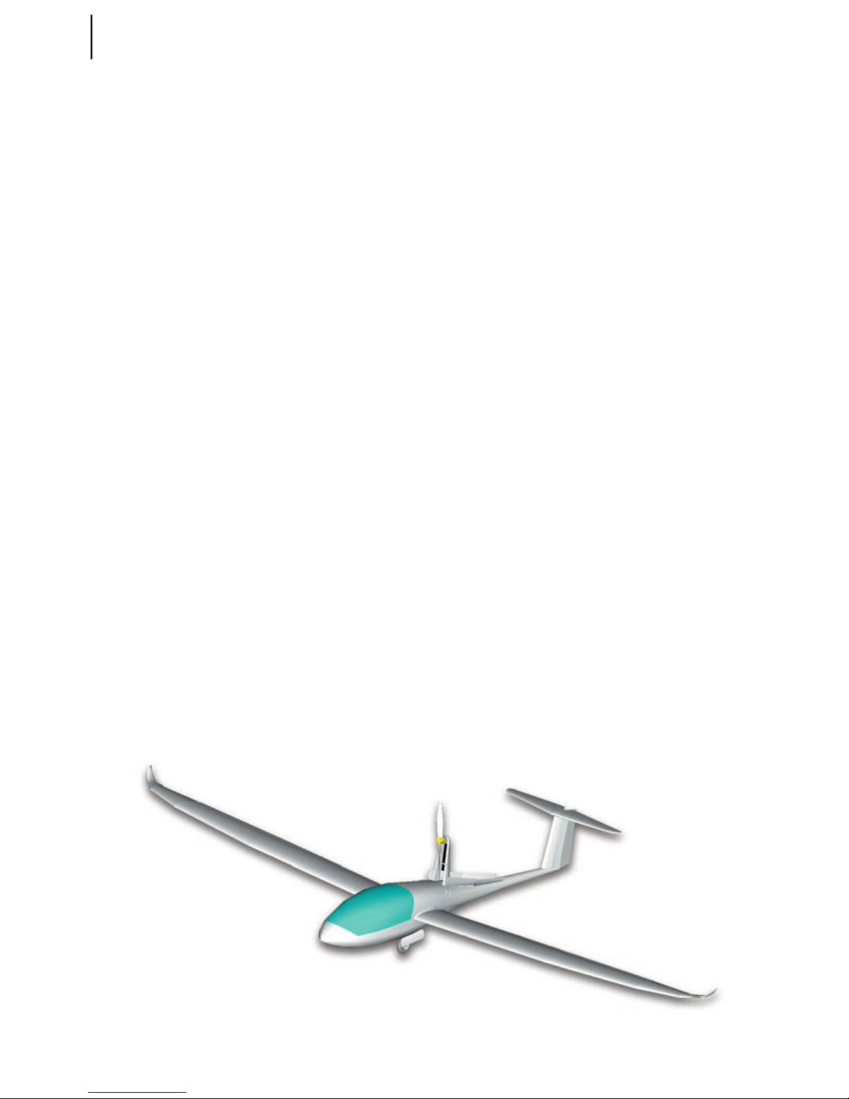
62
TAURUS ELECTRO
www.pipistrel.si
Aircraft and systems on board
Taurus is a 15-meter-wingspan, side by side
T-tail motorglider made almost entirely of
composite materials. The wing is mid-mounted
cantilever type, propulsion system is fully retractable to enhance gliding performance
The undercarriage is a taildragger type with
two main, brake equipped wheels, which are
fully retractable. Tail wheel stearable through
rudder input.
Taurus features flaperons, which are interconnected flaps and ailerons presented in the
same deflecting surface. Flaps offer 5 settings:
neutral, 1st, T , L and the negative position of
which none have any impact on aileron deflections whatsoever. What is more, individual
main flight control levers make Taurus ideal for
initial as well as for advanced flight training.
All aileron, elevator and flap controls are connected to the cabin controls using self-fitting
push-pull tubes. Rudder deflects via cables.
The elevator trim is mechanical, spring type.
All aircraft ship with H type safety belts attached to the fuselage at three mounting
points. Rudder pedals can be adjusted to suit
your size and needs.
The batteries are in the fuselage, placed in
four metal boxes with dedicated connectors.
Charging must be carried out only with original Pipistrel dedicated chargers.
The motor/controller system Electro40/30 is
standard and the aircraft features the Master
On-board Computer (MOC) that provides
throttle-by-wire capability.
The cannopy is either transparent or bluetinted plexy-glass.
Main wheel brakes are hydraulicly driven disc
type. The hydraulic brake fluid used is DOT 4.
Cabin ventilation is achieved through special
ducts fitted onto the cannopy frame and may
be adjusted for crew’s comfort.
To enhance aerodynamics for gliding, Taurus
fully retracts the propulsion unit. This procedure is fully automated and invoked by only a
flip of a switch on the instrument panel.
Electric circuit enables the pilot to test individual circuit items. Navigational (NAV), and anti
collision (AC) lights are an option. The motor/
propeller compartment is fully enclosed and
separated from the cockpit.
Basic instruments come installed with operational limits pre-designated. EYS-MAN is standard equipment.
A ballistic parachute rescue system can be
installed as an option (in some countries e.g.
Germany the ballistic rescue system must be
installed).
Introduction

63
TAURUS ELECTRO
www.pipistrel.si
Composite parts are made of:
fabric: AFK 170, GG90, GG 120, GG160, GG200,
90070, 92110, 92125, 92140, 92145, KHW200
continous fibres: Tenax STS 5631
foam:
75 kg/m3 PVC 3mm, PVC 5 mm, PVC 8mm
honeycomb: kevlar 3mm
GFK: 3 mm, 5 mm, 7 mm of thickness
paint: acrylic
heat resistant protection glass-aluminium sandwich
Medal parts used are:
tubes: materials: Fe0146, Fe 0147, Fe0545, Fe1430, AC 100, CR41 in LN9369
sheet metal: materials: Fe0147 in Al 3571
rods: materials: Fe 1221, Fe 4732, Č4130, Al 6082, CR41 in Al 6362
cable: AISI 316
bolts and nuts: 8/8 steel
All composite parts are made of glass, carbon and kevlar fiber manufactured by Interglas GmbH.
All composite parts have been tested at a safety factor of 1.875.
All parts are made in moulds, therefore, no shape or structural differences can occur.
All design, manufacturing and testing complies with following regulations:
• Lufttüchtigkeitsforderungen für aerodynamisch gesteuerte Ultraleichtflugzeuge (LTF-UL) vom
30. Januar 2003, herausgegeben vom Luftfarht-Bundesamt
• JAR-1 microlight definition
• JAR-22 - certain sections
• JAR-VLA -certain sections
for Slovenian market also: Pravilnik o ultralahkih napravah Republike Slovenije.
All parts and materials present in Taurus Electro are also being used
in glider and general aviation industry and all comply with aviation standards.
Aircraft and systems on board
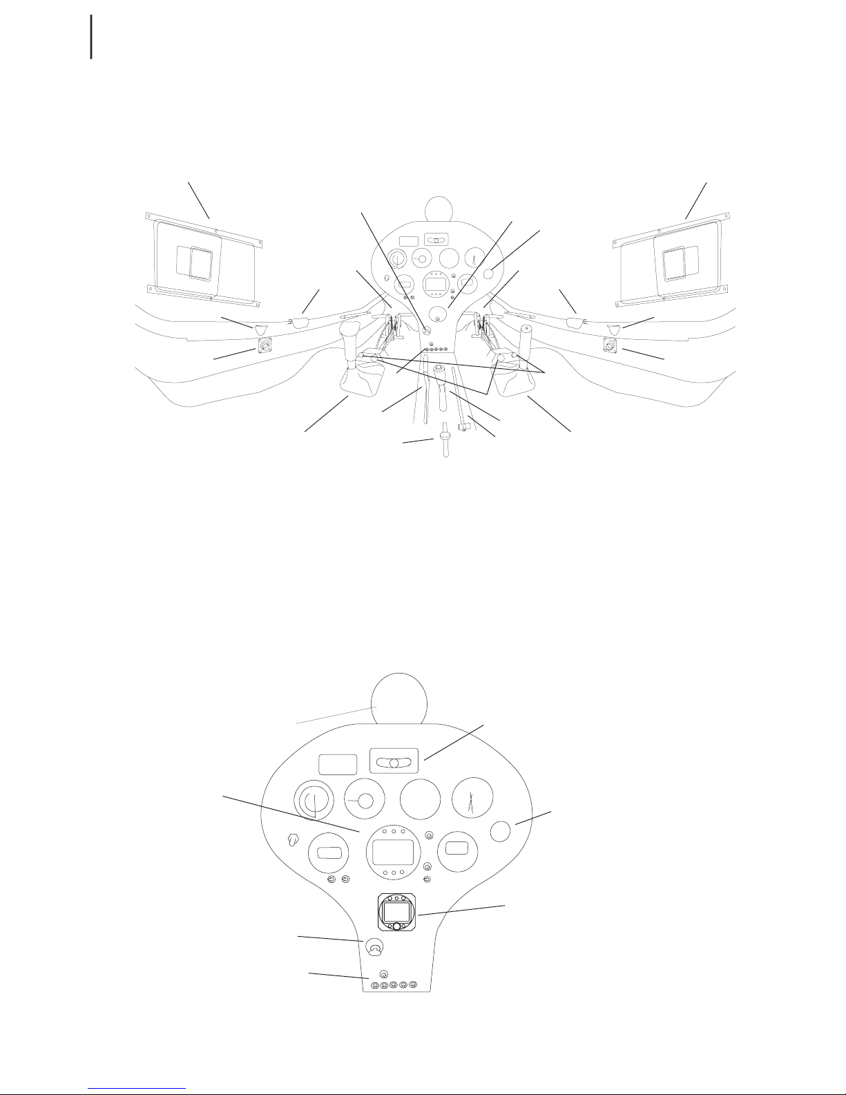
64
TAURUS ELECTRO
www.pipistrel.si
Cockpit levers
Taurus Electro’s cockpit levers are divided into two groups:
Individual control levers: pilot stick, rudeer pedals with belonging length adjustment levers
Shared control levers: ESYS-MAN (throttle control), flap lever, gear retraction lever, trim lever, air-
brakes lever, canopy lock levers, ventilation lever and emergency parachute release handle.
Instrument panel
Aircraft and systems on board

65
TAURUS ELECTRO
www.pipistrel.si
Taurus Electro comes standard with a modern, electronic instrument panel. The panel utilizes the
power of the ESYS-MAN control and monitoring instrument, which includes throttle control, system
enable, as well as motor retraction management. Besides the conventional instruments the panel includes a magnetic compass, a side-slip indicator, 12 V socket, cockpit ventilation lever, throttle lever,
master switch, fuses, CHT/EGT gauge and primary flight instruments.
Undercarriage
The undercarriage is a taildragger type with two main, brake equipped, retractable wheels and a
rudder-guided tail wheel. Main gear is retcracted / lowered by operating a lever located between
both seats, accessible to both crew. Once main gear is lowered it is locked into position automatically. Wheel brakes are both engaged simultaneusly when the airbrakes are fully extended and the
pilot continues to pull on the airbrake lever.
distance between main wheels: 0,68 m
distance between main and tail wheel axis:
4,403 m
tire:
4,00'' x 6'' (main wh.), 2,50'' x 4'' (tail wh.)
tire pressure
1,5 - 1,6 bar / 21-23 PSI (main wheels),
0,6 bar / 9 PSI (tail wheel)
brakes: disk type, engaged simultaneously upon full airbrake extension
brake fluid: DOT 4
Aircraft and systems on board
Main gear lowered and locked (side view)
Main gear retracted (side view)
Main gear lowered and locked
(front view)

66
TAURUS ELECTRO
www.pipistrel.si
Seats and safety belts
Seats have no stiff internal structure and do not offer different settings. All Taurus ultralight
motorgliders ship with H type safety belt attached to the fuselage at three mounting points.
Pitot-Static lines
The pitot tube is inside the nose-tip. Pitot lines made of plastic materials lead from there to the instrument panel and are secured from non-intentional damage. Static ports are located on both sides
of the nose below the middle line and are marked with red circles. Static lines are led from the static
ports to the instrument panel, are of composite materials and secured.
Air brakes (spoilers)
Spoilers are most commonly used to increase drag and steepen the final approach.
During takeoff, climb and cruise spoilers MUST be retracted and locked (handle in cockpit in full
forward position). To unlock and extend spoilers, pull the handle upwards.
Flap settings
Taurus Electro is equipped with flaperons which offer five (5) different flap settings. Apart from the
limitations for extesion of +9° and +18° flaps, there are recommendations for the use of flaps with
different speed-ranges and types of flight operation.
Recommended speed ranges for certain flap settings in when gliding:
flaps in negative position; -5° (up): faster than 150 km/h km/h (80 kts)
flaps in neutral position; 0° (neutral): 120 - 150 km/h (65 - 80 kts)
flaps in 1st position; +5° (down): 90 - 120 km/h (50 - 65 kts)
flaps in T position; +9° (down): 80 - 90 km/h (43 - 50 kts)
flaps in L position: +18° (down): FINAL APPROACH - LANDING
Water ballast reservoir
Taurus Electro is equipped with a water ballast reservoir to provide for better control over the aircraft’s centre of gravity. The reservoir is placed in front-cabin and secured with two (2) fastening
butterfly screws with as the retaining mechanism. The quantity of the reservoir is 9 litres (9 kg). Lever
arm for centre of gravity calculations is -1800 mm. There are placards on the instrument panel indicating minimum and maximum allowable crew weight with and without (9 kg) water ballast. The
mentioned figures are to be respected at all times!
WARNING! CHECK THE WATER BALANCE RESERVOIR IN FRONTCABIN AND VERIFY
CREW’S WEIGHT BEFORE EVERY FLIGHT AS IT MAY INFLUENCE THE CENTRE OF GRAVITY OF
AIRCRAFT TO THE POINT WHERE IT IS NO LONGER CONTROLLABLE!
Aircraft and systems on board
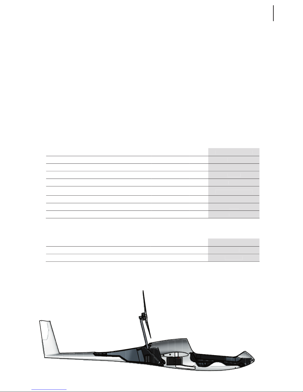
67
TAURUS ELECTRO
www.pipistrel.si
Power plant, propeller and energy storage
Taurus Electro has a out-runner motor mounted on top of the motor arm and provides direct-drive
to the propeller. The motor is a 3-phase synchonus motor with permanent magnets, exibits high
torque and above average efficiency ratings. The cooling is provided via incident air. The power controller is mounted inside the fuselage in an IP54 casing and is aircooled via a dedicated cooling duct.
The system is controlled via the color-display EYSY-MAN cockpit interface instrument. It indicates the
drive mode and important parameters to the pilot and provides the interface for engine retraction
and extension. Everything is operated via two (2) toggle switches and a rotatable knob. The first toggle switch is the system enable (on/off) switch while the second toggle switch is the motor position
selector »up/down« i.e. extended or retracted. This process is fully automated – the propeller is positioned and held in place while the motor extends or retracts. The pilot only selects the desired mode
with the toggle switch. The rotary encoder acts as the throttle selector. The ESYS-MAN also communicates with the Battery-Management-System and delivers information about the state of charge
, battery health information and monitors the charging. All components communicate via the CAN
interface with a proprietary communication protocol.
Motor:
TEMPERATURE °C / ELECTROMOTOR
40 kW
30 kW
40° C
2200
take-off rpm (typical)
2150
climb rpm (typical)
Controller:
45-55° C
WARNING! DO NOT, UNDER ANY CIRCUMSTANCES, ATTEMPT TO USE ANY OTHER
BATTERIES, OTHER THAN PIPISTREL FACTORY ORIGINAL BATTERY SYSTEM, WITH THIS MOTOR/
CONTROLLER.
Aircraft and systems on board

68
TAURUS ELECTRO
www.pipistrel.si
Aircraft and systems on board
ESYS-MAN
electric system control control & monitoring instrument
In order to simplify aircraft handling, the ESYS-MAN system takes complete control over the propulsion unit except, including the “throttle” . The system is very light and reliable as all switches and
sensors used to monitor the operations are inductive type and as such not sensitive to vibration,
mechanical damage and/or dirt. ESYS-MAN provides protections to system and is networked to the
power controller, motor arm controller, BMSs and charger via CAN bus.
System enable switch (ON/OFF) – This is the switch that enables the power to the system. When
set to ON (up), the status of the system will be confirmed with the System Status LED. This is the first
switch to be enabled and last to be disabled during the operation of the propulsion system.
System Status LED – Green means ON (OK), permanent RED is ERROR (see screen for error
message). Only active when System enable is set to ON.
Position selector (UP/DOWN) – use this switch to extend or retract the motor. The procedure is
fully automated (see next page!).
Throttle (RPM selector) – rotary knob that acts as the throttle command. Rotate right for
incremental RPM increase and left for incremental RPM decrease. The throttle bar (orange) below the
RPM and PWR fields on the display corresponds to current throttle level. Depressing the button for 2
seconds will overrun the current throttle setting and initiate full power immediately (should only be
used in emergency).
Bottom status LEDs - indication of motor position (extended or retracted). See above schematic
for explanation. Simultaneous flashing of both LEDs in RED indicates that the system is in transition
between the Extended and Retracted position (normal operation). Permament red indicates error.

69
TAURUS ELECTRO
www.pipistrel.si
Aircraft and systems on board
Extending the propeller arm:
WARNING! BEFORE EXTENDING THE PROPELLER ARM IN-FLIGHT, SET FLAPS TO T STAGE AND
REDUCE SPEED TO 80 KM/H (450KTS) OR BELOW.
1. Switch the System enable to ON (pull switch and move up).
This activates the system. Wait for System Status LED to turn GREEN (typically less than 5 sec).
2. Switch the Position selector switch to UP (pull switch and move up).
The electric brake will hold the propeller steady when it is moving towards the extended position.
Do not touch the unit until the LEFT status LED turns GREEN.
Running the motor (continued from Extending the propeller arm):
CAUTION! BEFORE STARTING-UP THE ENGINE, VERIFY THE PROPELLER ARM IS EXTENDED AND
PROPELLER IN VERTICAL POSITION BY CHECKING THE COCKPIT MIRROR.
1. Confirm the “PROP CLEAR” message on the ESYS-MAN display.
Confirm by clicking (pressing) the throttle knob. This is a safety precaution.
2. Rotate the throttle knob to select RPM (add power)
When the motor is running, the display will show motor RPM.
Also notice the throttle bar indicator.
Retracting the propeller arm:
WARNING! BEFORE RETRACTING THE PROPELLER ARM IN-FLIGHT, SET FLAPS TO T STAGE
AND REDUCE SPEED TO 80 KM/H (45 KTS). A COOLING PERIOD IS NOT REQUIRED.
1. Reduce RPM to zero (rotate throttle knob left) and monitor the throttle bar.
Monitor the RPM dropping towards zero.
2. Switch the Position selector switch to DOWN (pull switch and move down).
The electric brake will initiate propeller positioning. Once propeller is positioned, the retraction will continue automatically. Do not touch the unit and wait until the RIGHT status LED turns
GREEN!
3. Switch the System enable switch to OFF (pull switch and move down).
This deactivates the system.
Shutting-down the motor IN FLIGHT:
WARNING! WHEN IN FLIGHT, SHUTTING DOWN THE SYSTEM IS ONLY PREMITTED WHEN
THE PROPELLER IS IN THE RETRACTED POSITION. ON GROUND, THIS PRECAUTION IS NOT
VALID.
1. Retract the propeller arm
2. Switch the system enable switch to OFF (down)
WARNING! ALWAYS WAIT BEFORE THE SYSTEM IS CONFIRMED IN FULL EXTENDED OR
FULL RETRACTED POSITION BEFORE OPERATING THE MASTER SWITCH OR THE SYSTEM
ENABLE SWITCH! THE PROPELLER BRAKE IS ELECTRIC AND DOES NOT WORK WITHOUT POW
ER. IN FLIGHT AND WITH THE SYSTEM IN THE MIDDLE OF RETRACTION, CUTTING THE POWER
WILL RESULT IN PROPELLER DAMAGE!
TAURUS ELECTRO
www.pipistrel.si
Energy storage & charging
description: 4 metal boxes which include battery cells,
BMS and communication modules,
power and signal connectors
battery capacity:
(standard configuration)
4.75 kWh
battery capacity:
(optional configuration)
7.10 kWh
useful bat. capacity (recommended, std) 3.8 kWh
useful bat. capacity (recommended, optional) 5.7 kWh
CAUTION! IN ORDER TO KEEP THE BATTERY LIFE, IT IS NOT RECOMMENDED TO DISCHARGE
THE BATTERY BELOW 20% CHARGE. USEFUL RANGE IS CONSIDERED TO BE BETWEEN 20%-100%
OF SYSTEM CHARGE.
CAUTION! FOR BATTERY PROTECTION, THE ESYS-MAN WILL CUT THE POWER (AFTER A
WARNING) AT 10% BATTERY CHARGE. THE REMAINING IS USED FOR MOTOR RETRACTION AND
POWER SUPPLY TO AVIONICS.
The batteries are organised in 4 metal boxes, which include the battery cells, the Battery
Management System, communication modules as well as power and signal connectors. Two of the
boxes are positioned behind the fuselage bulkhead, two are in front of the same bulkhead.
Make sure that all the conectors (2x power connectors, 1x CAN BUS connector per box) are fastened
properly before each flight.
For storage, it is recommended to disconnect the RED (+) power connector on the box behind the
cockpit section. This will physically disconnect the high-voltage part of the propulsion system. Make
sure you reconnect the battery before next flight.
Battery management system
Each of the battery boxes have an independent BMS, monitoring and ballancing system voltage. All
units communicate to the ESYS-MAN and log data from each individual battery cell. In case of an
error, ESYS-MAN will display a message (error code). Contact manufacturer if this happens. Under
normal circumstandes the BMS requires no human intervention and is a fully automated system that
takes care of itself.
Standard
270 V
230 V - 250 V
5° C
Allowable temperature range for storage
CAUTION! TEMPERATURES BELOW 10°C WILL RESULT IN DECREASE OF BATTERY CAPACITY.
PLAN YOUR FLIGHT ACCORDINGLY.
WARNING! DO NOT, UNDER ANY CIRCUMSTANCES, ATTEMPT TO CHARGE THE BATTERIES
WITH ANY THIRD PARTY CHARGERS. ONLY PIPISTREL ORIGINAL EQUIPMENT MUST BE USED.
WARNING! RESPECT OPERATING AND STORAGE TEMPERATURE LIMITS AT ALL TIMES.
FAILURE TO DO SO MAY RESULT IN BATTERY DAMAGE.
Aircraft and systems on board

TAURUS ELECTRO
www.pipistrel.si
Aircraft and systems on board
Electrical system
Cockpit electrical system
power supply: DC/DC converter converts high voltage to usable 12 V cockpit voltage
master switch: key type, position 1 - Avionics, position 2 - ALL ON
maximum continous
power load:
20 A
NOTE: THE ENERGY TO POWER THE AVIONICS COMES FROM THE MAIN ENERGY STORAGE
BATTERIES. THERE IS NO SEPARATE BATTERY FOR AVIONICS. IT IS ALMOST IMPOSSIBLE FOR
THE AVIONICS TO DISCHARGE THE BATTERIES FULLY, HOWEVER BE AWARE THAT LONG FLIGHTS
UNDER INTENSIVE AVIONICS USE (TRANSPONDER, RADIO, GPS, ETC.) WILL DISCHARGE THE
BATTERY AND RESULT IN SHORTER MOTOR-ON ENDURANCE.
Battery box with connectors
Charging
The charger is a dedicated charger with approximately 1 kW charging power. Charge time will vary
upon battery charge status and may be between 30 minutes to up to 7 hours. The charger is a worldwide chager, which can be connected to any 110 V and 240 V, 50 Hz or 60 Hz electrical grid or the
Solar Trailer.
Once connected, monitor the system charge status on the ESYS-MAN. You can disconnect the charger at any point, even if the batteries are not completely full.
CAUTION! DURING PERIODS OF NOT USING THE AIRCRAFT, IT IS REQUIRED TO PERFORM A
KEEP-ALIVE (MAINTENENCE) CHARGE ONCE EVERY 30 DAYS. TO DO SO, CONNECT THE CHARGER
FOR A MINIMUM OF 2 HOURS. THIS WILL REFRESH THE BATTERIES AND KEEP THE SYSTEM IN A
HEALTHY STATE. ALSO, AFTER A PERIOD OF NO-FLYING ACTIVITY, PERFORM A FILL-UP CHARGE 24
HOURS BEFORE THE ACTUAL FLIGHT.
WARNING! IF YOU HAVE PURCHASED ANOTHER SET OF BATTERIES, MAKE SURE YOU DO
NOT MIX THE BOXES BETWEEN SETS. THE GROUP OF SAME 4 BOXES MUST ALWAYS BE USED! THE
BOXES COME DESIGNATED WITH COLOUR DOTS. USE ONLY THE BOXES WITH SAME COLOR DOTS.

TAURUS ELECTRO
www.pipistrel.si
Aircraft and systems on board
Schematic of complete electrical system

TAURUS ELECTRO
www.pipistrel.si
Aircraft and systems on board
Cooling system
All propulsion system components are air-cooled. The motor receives the incident stream of air
whereas the power controller has dedicated ducting to deliver air to the heatsink.
Wheel brake system
Wheel brake system features common braking action for both main wheels. Wheel brakes are hydraulicly driven disc type.
Wheel brakes are operated by extending the airbrake lever past the full extension point.
Hydraulic brake fluid used for hydraulic type brakes is DOT 4.
If the braking action on your aircraft is poor even while the full backward pressure is applied on the
airbrake handle, please see chapter on Handling and Maintenance of this manual to learn how to
rectify this problem.

TAURUS ELECTRO
www.pipistrel.si
Aircraft and systems on board
This page is intentionally left blank.
TAURUS ELECTRO
www.pipistrel.si
Introduction
Inspection periods
Repairs and
spare part replacements
Preventative maintenance
Special check-ups
Draining and refuelling
Tie down
Storage
Cleaning
Keeping your aircraft in
perfect shape
Handling
and maintenance

TAURUS ELECTRO
www.pipistrel.si
Introduction
This chapter determines handling and (preventative) maintenance terms. Also, recommended
ground handling is presented.
THE FOLLOWING ARE PROVISIONAL VALUES SUBJECT TO CHANGE WITHOUT NOTICE!
Inspection periods
See “Service manual”.
Repairs, spare part replacements and
preventative maintenance
All major repairs and spare part replacements MUST be done by
authorised service personnel.
However, you are encouraged to take care of preventative maintenance yourself. This includes:
tire and wheel bearings replacements, safety wire replacements, door and safety harness replacement, light bulb replacements, spark plugs replacements and air filter replacements.
The table below indicates recommended maintenance periods (see Service manual for detailed information).
Table legend:
C
Check-up - visual only, check for free play and whether everything is in position - DO IT YOURSELF
CL
Cleaning - DO IT YOURSELF
LO
Lubricating, oiling - lubricate all designated parts and spots using proper lubricant -
DO IT YOURSELF
R
Replacement - replace designated parts regardless of state and condition.
You are encouraged to DO undemanding replacements YOURSELF, otherwise have replacements
done by AUTHORISED SERVICE PERSONNEL
SC
Special check-up - measuring, verifying tolerances and functionality - DONE BY AUTHORISED
SERVICE PERSONNEL ONLY
O
Overhaul
EACH
daily
first 5
50
250
500
WING AND TAIL SURFACES
WING AND TAIL SURFACES
SC
O
surface and structure condition
C
SC
deflections without free play
deflections without free play
C
SC
C
SC
C
self-adhesive sealing tape
self-adhesive sealing tape
C
C
CCSC
drain holes
drain holes
CL

TAURUS ELECTRO
www.pipistrel.si
EACH
daily
fist 5
hours
50
hours
100
hours
250
hours
500
hours
1.000
hours
10.000
hours
FUSELAGE
SC O
surface and structure condition
C SC
elevator control tube bearing
C SC
doors, hinges
C C SC LO
rudder control wires and hinges
C C SC
drainage holes
C CL
CABIN
SC O
control levers, instr. panel, seats
C SC
control levers’ free play
C C SC
intstruments and pitot-static
C SC test
glass surfaces: clean, attached
C C SC
rivet condition
C SC
safety harnesses and attach. points
C SC
parachute rescue sys. activation handle
C SC
wing connectors: electrical
C C SC
bolts and spar pins
C C SC
wing main bushings, control connectors
SC
UNDERCARRIAGE
O
tires
C C R
wheel axis and wheels
C
wheel bearings
C SC R
wheel fairings
C C C
tail wheel mounting bolt
check and fasten every 50 landings
CONTROLS
R
general free play
C C SC
control stick
C LO SC
rudder pedals (damage, centered, paral.)
C C C LO
rudder wire rope
C SC
bolts, visible bearings (tail, fuselage)
SC LO
difficult-to-reach bearings (wings, under cabin floor)
LO
aileron, elevator and rudder hinges
SC LO
equal spoiler extension, undisrupted m.
C SC LO
spoiler plate springs stiffness
C
flap handle
C SC LO
elevator trim
C LO
springs: flaps, rudder, el. trim, stablizer main fastening bolt
LO
C R
airbrakes internal connector rod (if flown or stored where possibilty for
corrosion is increased (oceanside, wet regions...)
replace every 2 years
spoilers’ (airbrakes’) drive fine adjustment
see page 73 for detailed description
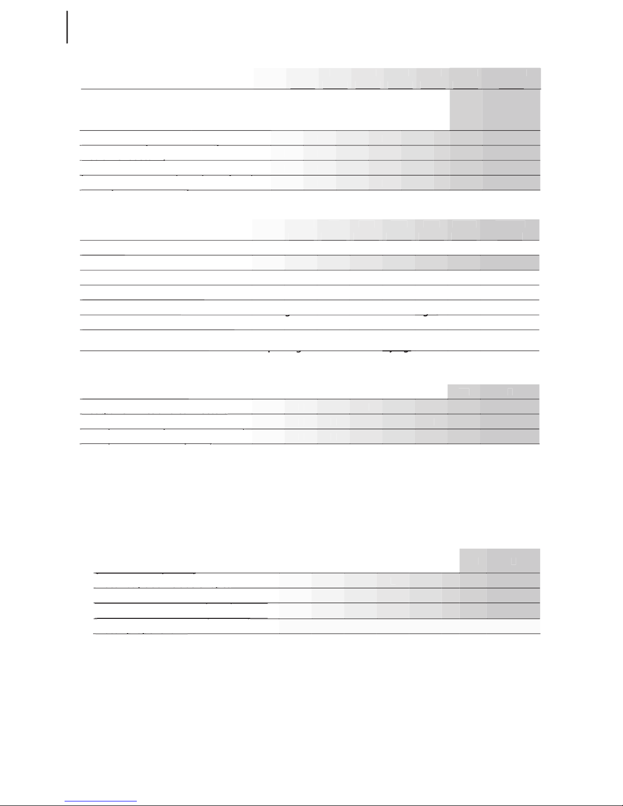
TAURUS ELECTRO
www.pipistrel.si
EACH
daily
first 5
50
300
500
SC
O
C
C
C
C
C
C
whole pitot-static lining
whole pitot-static lining
C
C
EACH
daily
first 5
50
300
500
visual inspection, clean
C SC
Check driveshaft axial free play, tighten main bearing every 10 hours of motor operation.
Check and clean cooling duct/heatsink before each flight
Check and clean cooling duct/heatsink before each flight
Check and clean cooling duct/heatsink before each flight
Check and clean cooling duct/heatsink before each flight
SC
C
C
fuses (instrument panel - automatic)
fuses (instrument panel - automatic)
C
C
C C
C
C C
fuses (motor electrical panel)
fuses (motor electrical panel)
C
C
Current maintenence schedule for the powertrain is preliminary and determined according to
Pipistrel’s best knowledge and expertise. As such, the maintenence schedule for the powertrain is
subject to change.W hen in doubt, contact a Pipistrel representative with any questions.
SC
C
C R
C R
CHECK CONDITION EVERY DAY
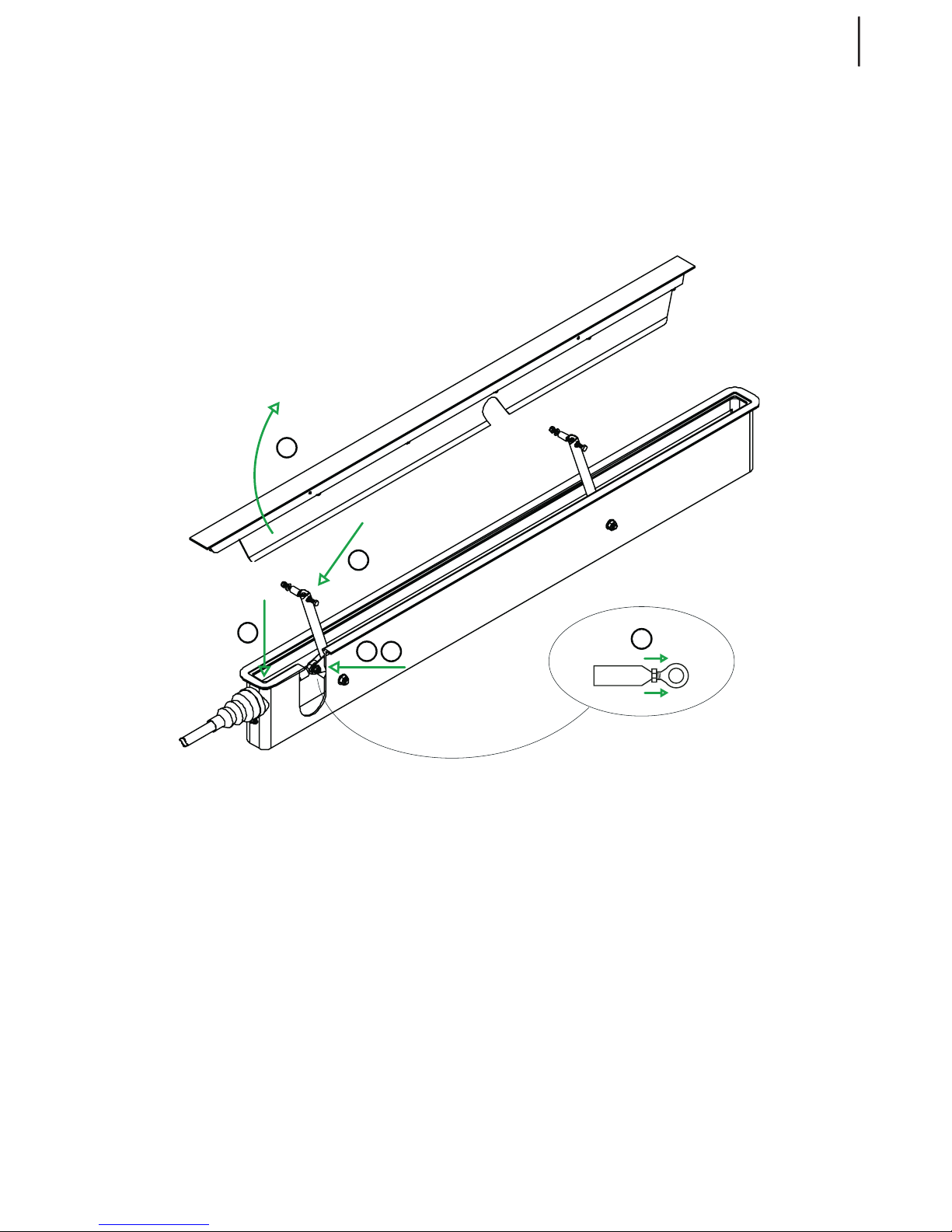
TAURUS ELECTRO
www.pipistrel.si
Spoilers (airbrakes) drive fine adjustment
CAUTION! PERFORM THIS OPERATION ONLY ONCE AFTER FIRST 50 FLIGHT HOURS!
CHECK SPOILERS THOROUGHLY FOR UNOBSTRUCTED, SMOOTH AND EVEN EXTENTION
BEFORE EVERY FLIGHT!
Schematic of spoilers’ (airbrakes’) drive fine adjustment
(see next page for detailed description)
1
2
3
4
5
4

80
TAURUS ELECTRO
www.pipistrel.si
Perform the adjustment as follows:
Unscrew and remove the inner horizontal bolt of the airbrake’s plate. Do not lose any parts!
Lift the airbrake in order to make room for further operation.
Unscrew and remove the bolt attaching the rod-end bearing to the airbrake’s plate lever.
Do not lose any parts!
Rotate the rod-end bearing fine-setting nut 360° so that the rod end moves towards the
other end of the airbrake’s box (length of rod increases). Make sure you secure this nut
after turning it for 360°!
Grease the drive around the rubber sleave inside the airbrake’s box using rubber-nonagressive lubricant spray.
Once you have accomplished this, repeat steps 1-3 in opposite order (3,2,1). Make sure you apply adhesive (e.g. Loctite) on all screws when reattaching!
Perform the procedure at the other airbrake as well.
When finished, verify airbrakes for equal extension.
WARNING! SHOULD THE AIRBRAKES NOT RETRACT EVENLY, APPLY STEP 4 ACTION AGAIN
FOR THE AIRBRAKE, WHICH REMAINS HIGHER WHEN RETRACTING.
Clicking noise behind the cockpit
The wings are factory fitted to the fuselage to make a tight fit at approximately 20° Celsius. When exposed to low temperatures, materials shrink. Therefore, flying in the winter or in cold temperatures,
you may encounter “click-clack” like noises above your head. The remedy for this unpleasant noise
is to add washers, tipically of 0,5 mm thickness in-between wing and fuselage. Washers must be
added both at rear and front bushings on one side of the fuselage only!
WARNING! IT IS MANDATORY TO CONSULT THE MANUFACTURER OR AUTHORISED SERVICE
PERSONNEL BEFORE APPLYING WASHERS!
Bleeding the hydraulic brake system
Two persons are needed to perform the hydraulic brake system bleeding in the traditional way.
First, fill up the hydraulic fluid reservoir, mounted on the bottom of the fuselage behind the cockpit,
with DOT 4 fluid. Then, one person should pump the hydrulic oil towards the main landing wheels
using pumping motion on the airbrake handle. After 5-10 complete forward-aft movements, hold
the airbrakes handle in fully engaged position. Now, the second person must open the bleed valve
on one of the main wheels to bleed the air pockets from the hydraulic lines. Close the bleed valve
each time before continuing with the pumping motion on the airbrake handle.
Repeat this procedure until no more air is bled out of the bleed valve.
Then perform the same procedure for the other main wheel.
WARNING! SHOULD YOU ENCOUNTER ANY DIFFICULTIES DURING THIS PROCEDURE OR
THE AIR POCKETS WOULD NOT VENT, PLEASE CONSULT THE MANUFACTURER OR AUTHORISED
SERVICE PERSONNEL FOR FURTHER INSTRUCTIONS.
1
2
3
4
5
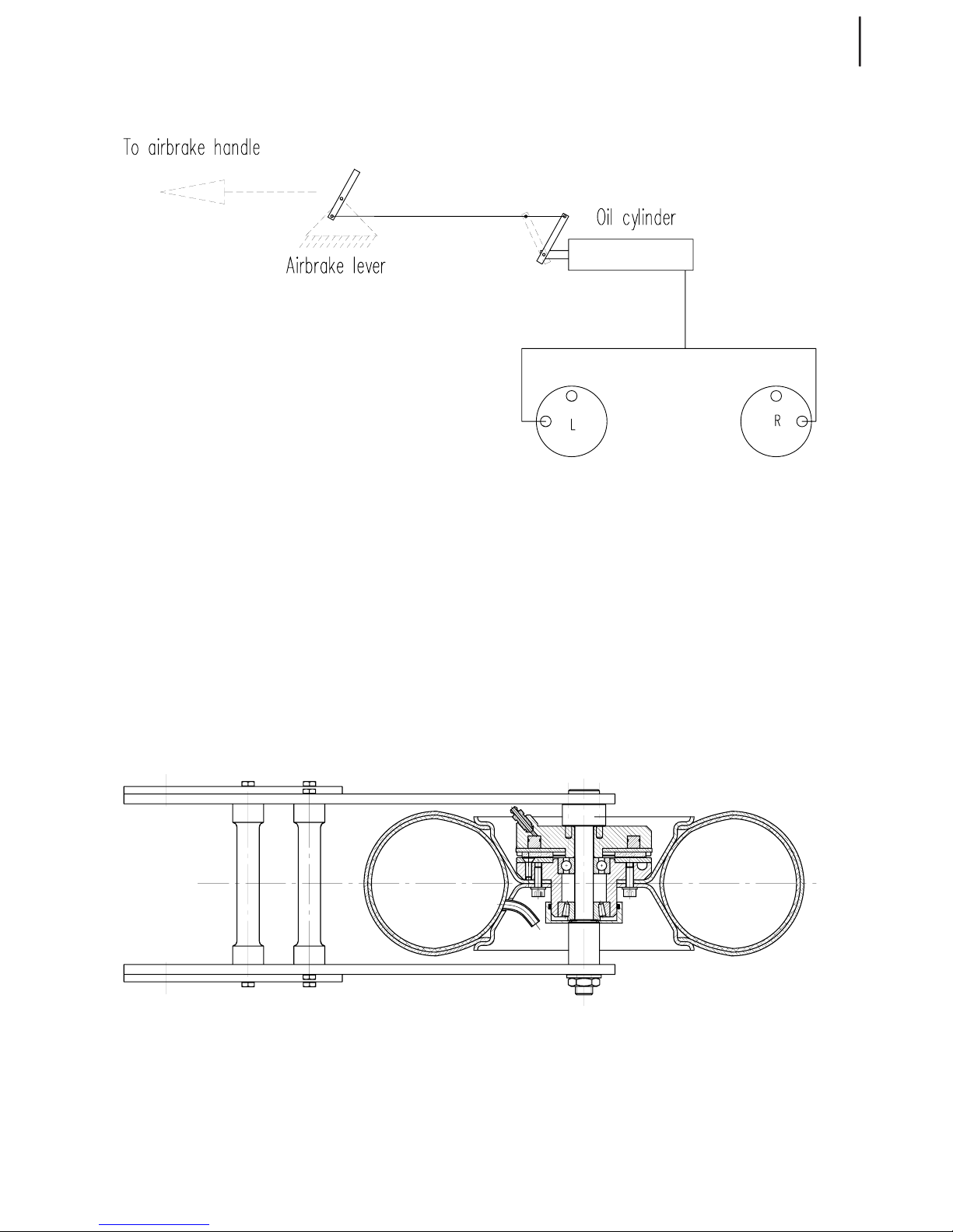
81
TAURUS ELECTRO
www.pipistrel.si
Poor braking action
In case you notice poor braking action even when hydraulic brakes are fully engaged (airbrake lever
full back), it is not necessary the air bubbles in the hydraulic lining, which is causing the problem.
The main wheel’s main axis’ nut (especially after a wheel and/or axis replacementnut) may be tightened incorrectly so that the brake shims do not make contact with the brake plate. Please consult
the manufacturer or authorised service personnel for further information.
Schematic of wheel and wheel brakes
Schematic of hydraulic brakes’ lining

82
TAURUS ELECTRO
www.pipistrel.si
Special check-ups
After having exceeded VNE or landed in a rough manner:
check the undercarriage, fuselage & wing surfaces and main spars for abnormalities. It is highly
recommended to have the aircraft verified for airworthiness by authorised service personnel.
Tie down
Tie down the Taurus using dedicated screw-in rings which attacth to the adequate threads on the
bottom side of the wing. Alternatively you may also tie down the wings using a rope over the winglet area, however, make sure you place a soft piece of foam or equivalent between the wing surface
and the rope, so as not to cause surface and structural damage in case of over-tightening the rope.
Tie down the tail by leading the rope over the fuselage just where the vertical tail surface meets the
fuselage. Tighten this rope in backwards (45°) direction.
Parking and Storage
The aircraft is ideally stored in a hangar. For increased in-hangar manouvrability use of original pushcart or free turning tail wheel adapter is recommended.
Even for over-night storage it is recommended to leave the spoiler (airbrake) handle
unlocked in order to reduce pressure on plate springs in order to maintain their original stiffness.
As for the parachute rescue system make sure the activation handle safety pin is inserted every time
you leave the aircraft.
CAUTION! SHOULD THE AIRCRAFT BE STORED AND/OR OPERATED IN AREAS WITH HIGH AT
MOSPHERIC HUMIDITY PAY SPECIAL ATTENTION TO EVENTUAL CORROSION OF METAL PARTS,
ESPECIALLY INSIDE THE WINGS. UNDER SUCH CIRCUMSTANCES IT IS NECESSERY TO REPLACE
THE SPOILERS AIRBRAKES CONNECTOR ROD EVERY 2 YEARS.
CAUTION! MAKE SURE THE CABIN IS CLOSED AND LOCKED EVERYTIME YOU LEAVE THE AIR
CRAFT. OTHERWISE THE CANOPY FRAME MAY NO LONGER FIT THE FUSELAGE AFTER A WHILE
AS PLEXIGLASS AND FIBER HAVE SIGNIFICANTLY DIFFERENT STRETCH COEFICIENTS.
CAUTION! WHENEVER LEAVING THE AIRCRAFT PARKED UNDER SUNSHINE, ALWAYS COVER
THE CANOPY WITH A LIGHTCOLOURED CLOTH TO PREVENT OVERHEATING. DO THIS AFTER
YOU HAVE CLOSED AND LOCKED THE CANOPY USING BOTH LATCHES.
Cleaning
Use pure water and a soft piece of cloth to clean the aircraft exterior. If you are unable to remove certain spots, consider using mild detergents. Afterwards, rinse the entire surface thoroughly.
Always use pure water only to clean the glass surfaces, so as not to damage their protection
layers and coatings.
To protect the aircraft surface (excluding glass surfaces) from the environmental contaminants,
use best affordable car wax. (e.g. Sonax Extreme WAX Full Protection no.1)
The interior is to be cleaned with a vacuum cleaner.

83
TAURUS ELECTRO
www.pipistrel.si
Keeping your aircraft in perfect shape
Precautions
1) DO NOT USE ANY aggressive cleaning solutions and organic solvents, also the window cleaning
spray, benzene, acetone, aggressive shampoos etc.
2) If you must use an organic solvent (acetone) on small areas to remove certain glue leftovers
or similar, the surface in question MUST be polished thereafter. The only section where polishing
should be avoided is the edge on the wing where the sealing gasket is applied.
3) When flying in regions with a lot of bugs in the air, you should protect the leading edges of the
airframe before flight (propeller, wings, tail) with Antistatic furniture spray cleaner: “Pronto (transparent), manufacturer: Johnson Wax (or anything equivalent) – Worldwide”, approximate price is only $3
USD / €3 EUR for a 300 ml spray bottle. Using such spray, do not apply it directly onto the wing but
into a soft cloth instead (old T-shirts are best).
4) After having finished with flight activity for the day, clean the leading edges of the airframe as
soon as possible with a lot of water and a drying towel (chamois, artificial leather skin). This will be
very easy to do if you applied a coat of Pronto before flight.
Detailed handling (Airframe cleaning instructions)
Every-day care after flight
Bugs, which represent the most of the dirt to be found on the airframe, are to be removed with clean
water and a soft mop (can be also drying towel, chamois, artificial leather skin).
To save time, soak all the leading edges of the airframe first. Make sure to wipe ALL of the aircraft
surface until it is completely dry at the end.
Clean the propeller and the areas with greasy spots separately using a mild car shampoo with wax.
CAUTION! DO NOT, UNDER ANY CIRCUMSTANCES ATTEMPT TO USE AGGRESSIVE CLEANING
SOLUTIONS, AS YOU WILL SEVERELY DAMAGE THE LACQUER, WHICH IS THE ONLY PROTECTIVE
LAYER BEFORE THE STRUCTURAL LAMINATE.
When using the aircraft in difficult atmospheric conditions (intense sunshine, dusty winds, coastline,
acid rains etc.) make sure to clean the outer surface even more thoroughly.
If you notice you cannot remove the bug-spots from the leading edges of the aircraft, this means the
lacquer is not protected any more, therefore it is necessary to polish these surfaces.
CAUTION! DO NOT, UNDER ANY CIRCUMSTANCES ATTEMPT TO REMOVE SUCH BUGSPOTS
WITH ABRASIVE SPONGES AND/OR ROUGH POLISHING PASTES.

84
TAURUS ELECTRO
www.pipistrel.si
Periodical cleaning of all outer surfaces with car shampoo
Clean as you would clean your car starting at the top and working your way downwards using a soft
sponge. Be careful not to use a sponge that was contaminated with particles e.g. mud, fine sand)
not to grind the surface. While cleaning, do soak the surface and the sponge many, many times. Use
a separate sponge to clean the bottom fuselage, as is it usually more greasy than the rest of the airframe. When pouring water over the airframe, be careful not to direct it over the wing-fuselage joining section, parachute rescue system straps and cover, pitot tube, tail static probe and motor covers.
Always water the shampooed surfaces again before they become dry! Thereafter, wipe the whole of
the aircraft dry using a drying towel, chamois or artificial leather skin.
Also, clean the Mylar wing and tail control surfaces gaskets. Lift the gaskets gently and insert ONE
layer of cloth underneath, then move along the whole span of the gasket. Ultimately, you may wish
to apply Teflon grease (in spray) over the area where the gaskets touch the control surfaces.
Polishing by hand
Use only the highest quality polishing pastes WITHOUT abrasive grain, such as Sonax Extreme no.1
or similar. Start polishing on a clean, dry and cool surface, never in the sunshine!
Machine polishing requires more skills and has its own particularities, therefore it is recommended
to leave it to a professional.
Cleaning the Plexy-glass transparent surfaces
It is most important to use really clean water (no cleaning solutions are necessary) and a really clean
drying towel (always use a separate towel ONLY for the glass surfaces). Should the glass surfaces be
dusty, remove the dust first by puring water (not spraying!) and gliding your hand over the surface.
Using the drying towel, simply glide it over the surface, then squeeze it and soak it before touching the glass again. If there are bugs on the windshield, soak them with plenty of water first, so less
wiping is necessary. Ultimately, dry the whole surface and apply JT Plexus Spray ($10 USD / €10 EUR
per spray) or at least Pronto antistatic (transparent) spray and wipe clean with a separate soft cotton
cloth.

85
TAURUS ELECTRO
www.pipistrel.si
Conversion tables
Preflight check-up pictures
Appendix
Appendix
Appendix
Appendix

86
TAURUS ELECTRO
www.pipistrel.si
Conversion tables
kilometers per hour (km/h) - knots (kts) - metres per sec. (m/s)
km/h kts m/s km/h kts m/s km/h kts m/s
1,853 1 0,37 63,00 34 18,34 124,16 67 36,15
3,706 2 1,07 64,86 35 18,88 126,01 68 36,69
5,560 3 1,61 66,71 36 19,42 127,87 69 37,23
7,413 4 2,15 68,56 37 19,96 129,72 70 37,77
9,266 5 2,69 70,42 38 20,50 131,57 71 38,31
11,11 6 3,23 72,27 39 21,04 133,43 72 38,86
12,97 7 3,77 74,12 40 21,58 135,28 73 39,39
14,82 8 4,31 75,98 41 22,12 137,13 74 39,93
16,67 9 4,85 77,83 42 22,66 198,99 75 40,47
18,53 10 5,39 79,68 43 23,20 140,84 76 41,01
20,38 11 5,93 81,54 44 23,74 142,69 77 41,54
22,23 12 6,47 83,39 45 24,28 144,55 78 42,08
24,09 13 7,01 85,24 46 24,82 146,40 79 42,62
25,94 14 7,55 87,10 47 25,36 148,25 80 43,16
27,79 15 8,09 88,95 48 25,90 150,10 51 43,70
29,65 16 8,63 90,80 49 26,44 151,96 82 44,24
31,50 17 9,17 92,66 50 26,98 153,81 83 44,78
33,35 18 9,71 94,51 51 27,52 155,66 84 45,32
35,21 19 10,25 96,36 52 28,05 157,52 85 45,86
37,06 20 10,79 98,22 53 28,59 159,37 86 46,40
38,91 21 11,33 100,07 54 29,13 161,22 87 46,94
40,77 22 11,81 101,92 55 29,67 163.08 88 47,48
42,62 23 12,41 103,77 56 30,21 164,93 89 48,02
44,47 24 12,95 105,63 57 30,75 166,78 90 48,56
46,33 25 13,49 107,48 58 31,29 168,64 91 49,10
48,18 26 14,03 109,33 59 31,83 170,49 92 49,64
50,03 27 14,56 111,19 60 32,37 172,34 93 50,18
51,80 28 15,10 113,04 61 32,91 174,20 94 50,12
53,74 29 15,64 114,89 62 33,45 176,05 95 51,26
55,59 30 16,18 116,75 63 33,99 177,90 96 51,80
57,44 31 16,72 118,60 64 34,53 179,76 97 52,34
59,30 32 17,26 120,45 65 35,07 181,61 98 52,88
61,15 33 17,80 122,31 66 35,61 183,46 99 53,42
Appendix

87
TAURUS ELECTRO
www.pipistrel.si
knots (kts) - metres per second (m/s)
0
2
4
568
9
0
0
0,51
2,05
2,57
4,11
4,63
0,51
5,65
6,17
6,66
8,23
8,74
9,26
9,77
20
25,43
20,06
40
20,57
21,09
21,60
22,12
22,63
23,15
23,66
24,17
24,69
25,20
50
25,72
26,23
26,75
27,26
27,76
28,29
28,80
29,32
29,83
60
40,12
40,64
80
41,15
41,67
42,18
42,69
43,21
43,72
44,24
44,75
45,27
45,78
90
46,30
46,81
47,32
47,84
48,35
48,87
49,38
49,90
50,41
50,90
metres per second (m/s) - feet per minute (100 ft/min)
ft/min
ft/min
ft/min
0,502141,33
20,82
41
80,70
2
22
43,30
21,33
42
82,67
5,902345,27
21,84
43
84,64
2,03
47,24
22,35
86,61
2,5459,842549,21
22,86
45
88,58
6
26
51,18
23,36
46
90,53
27
53,15
23,87
47
92,52
4,06
8
28
55,11
24,38
48
94,48
4,57
9
29
57,08
24,89
49
96,45
5,08
59,05
25,45
50
98,42
5,58
21,65
61,02
25,90
51
6.09
23,62
62,92
26,41
52
6,60
25,51
64,96
26,92
53
27,55
66,92
27,43
54
29,52
68,89
27,94
55
8,12
28,44
56
8,63
28,95
57
9,14
29,46
58
9,65
29,97
59
20
20,32
40
60
Appendix

88
TAURUS ELECTRO
www.pipistrel.si
ICAN (international comitee for air navigation)
temperatures, relative pressure, relative density and
CAS to TAS correction factors as related to altitude
Altitude
Temperature
density
Cor. factors
feet
°C
-2.000
-610
66,13
0,971
-1
-305
62,56
0,985
0059
55,43
0,964
0,971
2.000
610
51,86
0,929
0,942
914
9,056
48,30
0,896
0,915
4.000
44,73
0,863
0,888
5.000
5,094
41,16
0,832
0,861
6.000
0,801
0,835
2134
0,771
0,810
8.000
2438
-0,850
0,742
0,785
9.000
2743
-2,831
26,90
0,714
0,761
-4,812
23,33
0,687
0,738
-6,793
0,661
0,715
-8,774
0,635
0,693
-10,75
0,611
0,671
4267
-12,73
9,074
0,587
0,649
4572
-14,71
5,507
0,564
0,629
4877
-16,69
0,541
0,608
5182
-18,68
-1,625
0,520
0,589
Appendix

89
TAURUS ELECTRO
www.pipistrel.si
Appendix
metres (m) to feet (ft) conversion table
feet
feet
(ft)
feet
0,304
20,42
67
219,81
0,609
2
6,562
20,72
68
223,09
0,914
9,843
21,03
69
226,37
21,33
229,65
5
21,64
232,94
6
21,91
236,22
2,133
22,96
40
22,25
239,50
2,438
8
26,24
22,55
242,78
2,743
9
29,52
42
22,86
246,06
43
23,16
249,34
23,46
252,62
45
23,77
255,90
42,65
46
24,07
259,18
4,267
45,93
47
24,38
80
262,46
4,572
49,21
48
24,68
81
265,74
4,876
52,49
49
24,99
82
269,02
5,181
55,77
50
25,29
83
272,31
5,48
59,05
51
25,60
84
275,59
5,791
62,33
52
25,90
85
278,87
6,096
20
65,61
53
26,21
86
282,15
6,400
21
68,89
54
26,51
87
285,43
6,705
55
26,82
88
288,71
23
56
27,12
89
291,99
24
57
27,43
90
295,27
25
82,02
58
27,73
91
298,55
26
85,30
59
28,04
92
8,220
27
88,58
60
28,34
93
8,530
28
91,86
61
200,1
28,65
94
8,830
29
95,14
62
203,4
28,90
95
9,144
98,42
63
206,6
29,26
96
9,448
64
209,9
29,56
97
9,750
65
213,2
29,87
98
20,12
66
216,5
99

90
TAURUS ELECTRO
www.pipistrel.si
Appendix
air pressure as related to altitude
altitude (m)
altitude (m)
-1000
866,5
25,6
-950
861,2
25,4
-900
855,9
25,3
-850
850,7
25,1
-800
845,5
25,0
-750
840,3
24,8
-700
835,2
24,7
-650
830
24,5
-600
824,9
24,4
-550
819,9
24,2
-500
814,8
24,1
-450
809,8
23,9
-400
804,8
23,8
-350
23,6
-300
2000
23,5
-250
2050
23,3
-200
2100
23,2
-150
2150
23,0
-100
2200
22,9
-50
2250
22,8
0
29,9
2300
22,6
50
29,7
2350
22,5
29,6
2400
22,3
995,4
29,4
2450
22,2
200
989,4
29,2
2500
22,1
250
983,6
29,0
2550
21,9
977,7
28,9
2600
21,8
971,9
28,7
2650
21,6
400
966,1
28,5
2700
21,5
450
960,3
28,4
2750
21,4
500
954,6
28,2
2800
21,2
550
948,9
28,0
2850
21,1
600
943,2
27,9
2900
21,0
650
937,5
27,7
2950
20,8
931,9
27,5
20,7
926,3
27,4
696,5
20,6
800
920,0
27,2
692,1
20,4
850
915,2
27,0
687,7
20,3
900
909,0
26,9
683,3
20,2
950
904,2
26,7
679,0
20,1
898,7
26,5
674,6
893,3
26,4
670,3
91
TAURUS ELECTRO
www.pipistrel.si
ICAO standard atmosphere
(m)
(ft)
(°C)
(°K)
T/T
0
p
(mmHg)
p
(kg/m
)
p/p
0
r
(kgs
/m
)
g
(kg/m4)
d
V
s
n*10
6
(m2/s)
-1000
-3281
21,5
294,5
854,6
0,137
0,957
-900
-2953
20,8
293,8
844,7
0,136
0,958
-800
-2625
20,2
293,2
835
0,134
0,962
-700
-2297
292,5
825,3
0,133
0,967
-600
-1969
291,9
815,7
0,132
0,971
-500
-1640
291,2
806,2
0,131
0,976
400
-1312
290,6
0,129
0,981
-984
289,9
0,128
0,985
200
-656
289,3
0,127
0,990
-328
288,6
0,126
0,995
00288
760
0,125
287,3
0,997
0,988
0,123
0,990
200
656
286,7
0,995
0,976
0,122
0,980
984
286,0
0,993
9970
0,964
0,121
-1,191
0,971
400
285,4
0,991
9852
0,953
0,120
0,962
500
284,7
0,988
9734
0,942
0,119
0,952
600
284,1
0,986
9617
0,930
0,117
0,943
700
2297
283,4
0,984
699,0
9503
0,919
0,116
0,934
800
2625
9,8
282,8
0,981
690,6
9389
0,908
0,115
0,925
900
2953
9,1
282,1
0,979
682,3
9276
0,897
0,114
0,916
8,5
281,5
0,977
674,1
9165
0,887
0,113
0,907
7,8
280,8
0,975
665,9
9053
0,876
0,112
0,898
7,2
280,2
0,972
657,9
8944
0,865
0,111
0,889
4265
6,5
279,5
0,970
649,9
8835
0,855
0,110
0,880
4593
5,9
278,9
0,968
642,0
8728
0,844
0,109
0,872
4921
5,2
278,2
0,966
634,2
8621
0,834
0,107
0,863
5249
4,6
277,6
0,963
626,4
8516
0,824
0,106
0,855
5577
276,9
0,961
618,7
8412
0,814
0,106
0,846
5905
276,3
0,959
611,2
8309
0,804
0,104
0,838
6234
2,6
275,6
0,957
603,7
8207
0,794
0,103
0,829
2000
6562
2
275
0,954
596,2
8106
0,784
0,102
0,821
2100
6890
274,3
0,952
588,8
8005
0,774
0,101
0,996
0,813
2200
7218
0,7
273,7
0,950
581,5
0,765
0,100
0,986
0,805
2300
7546
0,0
273,0
0,948
574,3
0,755
0,099
0,976
0,797
2400
7874
-0,6
272,4
0,945
576,2
0,746
0,098
0,967
0,789
2500
8202
-1,2
271,7
0,943
560,1
0,736
0,097
0,957
0,781
2600
8530
-1,9
271,1
0,941
553,1
0,727
0,096
0,947
0,773
2700
8858
-2,5
270,4
0,939
546,1
0,718
0,095
0,937
0,765
2800
9186
-3,2
269,8
0,936
539,3
0,709
0,094
0,928
0,757
2900
9514
-3,8
269,1
0,934
532,5
0,700
0,093
0,918
0,749
Appendix

92
TAURUS ELECTRO
www.pipistrel.si
1
2
5
6
3
5
Wing root
Wing root
Wing root
2
4
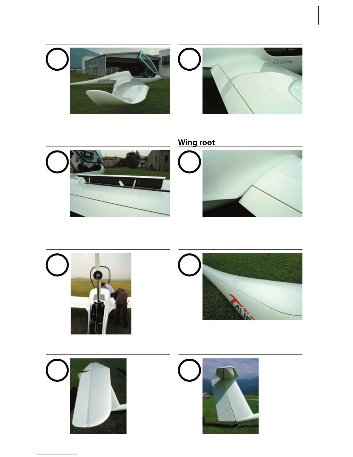
93
TAURUS ELECTRO
www.pipistrel.si
7
8
Starboard airbrake
9
10
Wing root
Horizontal tail surfaces
12
13
Vertical tail surfaces
10
11

94
TAURUS ELECTRO
www.pipistrel.si
This page is intentionally left blank.

95
TAURUS ELECTRO
www.pipistrel.si
Warranty statement
Warranty applies to individual parts and components only.
The warranty does not include costs related to the transport of the product, goods and spare parts as
well as costs related to the merchandise’ temporary storage. Pipistrel d.o.o. does not offer guarantee for
the damage caused by every day use of the product or goods. Pipistrel d.o.o. does not guarantee for the
Warranty voids:
- in case that the customer has not ratified the General Terms of ownership with his/her signature;
- in case the aircraft or the equipment is not used according to the Pipistrel d.o.o.’s instructions or
aircraft’s manual and eventual supplemental sheets;
- in case when the original additional and/or spare parts are replaced with non-original parts;
- in case additional equipment is built-in without Pipistrel d.o.o.’s prior knowledge;
- in case the purchased goods were changed or modified in any way;
- in case when the defect is caused by user’s deficient maintenance, inappropriate care and/or cleaning,
components in inadequate conditions, due to prolonged use of the product or goods, due to product
and/or parts’ over-stressing (even for a short duration), due to the fact a repair was not carried out
- in case parts that become worn out by every day use (e.g. the covers, pneumatics, electric instruments,
electric installation, bonds and bindings, cables, brake plates, capacitors, cooling devices, various pipes,
spark-plugs, exhaust systems…)
- the owner must ensure regular motor check-outs and maintenance.

Pipistrel d.o.o. Ajdovščina
podjetje za alternativno letalstvo
Goriška cesta 50a
SI-5270 Ajdovščina
Slovenija
tel: +386 (0)5 3663 873
fax: +386 (0)5 3661 263
e-mail: info@pipistrel.si
www.pipistrel.si
www.pipistrel.eu
 Loading...