

WARNING!
This document MUST be present inside the cockpit at all times.
Should you sell this aircraft make sure this document is given to the new owner.
© Copyright Pipistrel LSA s.r.l., Via Aquileia 75, 34170 Gorizia, Italy, EU
This publication includes the material required to be furnished to the pilot
by ASTM F2564, F2279 & F2295.
applies to LSA-GLIDER version of Sinus 912 LSA
own at 550 kgs MTOM
equipped with Rotax 912 UL (80 HP) engine
Tail-wheel version owners see
Supplemental sheet at the back of this manual
Pilot’s Operating Handbook
and Flight Training Supplement
REVISION 3
(24th April, 2015)
Aircraft Registration Number:
Aircraft Serial Number:

Sinus 912 LSA Glider 550 MTOW
www.pipistrel.eu
REV. 3
This page is intentionally left blank.
i-1

Sinus 912 LSA Glider 550 MTOW
www.pipistrel.eu
REV. 3
Performance - Specications
Sinus 912 LSA 80 hp Rotax 912
stall speed (aps extended) 34 kts (64 km/h)
stall speed (aps zero) 40 kts (74 km/h)
cruise speed (5300 RPM) 110 kts (205 km/h)
maximum speed at sea level 118 kts (218 km/h)
VNE 120 kts (222 km/h)
usable fuel capacity standard tanks 14.5 US gal/55 L, endurance 4.6 hours
usable fuel capacity long-range tanks 24.5 US gal/93 L endurance 7.7 hours
fuel ow at cruise speed 2.9 gph (11.2 l/h )
range at cruise speed (excl reserve, standard tanks) 505 NM
range at cruise speed (excl reserve, long range tanks) 850 NM
takeo - ground roll - at MTOM 430 ft (132 m)
takeo total distance over 50 ft obst. at MTOM 760 ft (232 m)
landing distance over 50 ft obst. (airbrakes) 885 ft (270 m)
absolute ceiling at MTOM (with engine running) 23,600 ft (7200 m)
NOTE Airbrakes are standard equipment and recommended for operations on runways short-
er than 2500 ft. The above performance gures are based on airplane weight at 1210 lbs (550 kg),
standard atmospheric conditions, level hard-surfaced dry runways and no wind. They are calculated valued derived from ight test conducted by Pipistrel LSA s.r.l. under carefully documented
conditions and will vary with individual airplanes and numerous factors (surface condition, temperature, water on wing, etc).
Sinus 912 LSA 80 hp Rotax 912
maximum weight takeo 1210 lbs (550 kg)
maximum weight landing 1210 lbs (550 kg)
standard empty weight 643 lbs (292 kg)
maximum useful load 568 lbs (258 kg)
baggage allowance 55 lbs (25 kg)
fuel capacity, usable 14.5/24.5 US gal
fuel capacity, usable 55 L/93 L
oil capacity (oil bottle) 3.1 quarts
engine Rotax 912 80 hp
propeller
xed pitch* dia. 63’’
1620 mm
*Propeller is a ground adjustable, two-blade composite propeller with metal hub, see chapter
Airplane and Systems Description for more details. Optional is Vario feathering propeller.
Noise levels
According to independent testing performed by German LBA-LTF noise regulations the aeroplanes,
the equivalent exhibited noise measures less than 60 dBa.
i-2

Sinus 912 LSA Glider 550 MTOW
www.pipistrel.eu
REV. 3
Coverage
The Pilot’s Operating Handbook (POH) in the airplane at the time of delivery from Pipistrel LSA s.r.l.
contains information applicable to the Sinus 912 LSA aircraft and to the airframe designated by the
serial number and registration number shown on the Title Page. All information is based on data
available at the time of publication.
This POH consists of ten sections that cover all operational aspects of a standard equipped airplane.
Section 10 contains the supplements which provide amended operating procedures, performance
data and other necessary information for airplanes conducting special operations and/or are
equipped with both standard and optional equipment installed in the aeroplane. Supplements are
individual documents and may be issued or revised without regard to revision dates which apply
to the POH itself. The Log of Eective Pages should be used to determine the status of each supplement.
Revision tracking, ling and identifying
Pages to be removed or replaced in the Pilot’s Operating Handbook are determined by the Log of
Eective pages located in this section. This log contains the page number and revision level for each
page within the POH. As revisions to the POH occur, the revision level on the eected pages is updated. When two pages display the same page number, the page with the latest revision shall be used
in the POH. The revision level on the Log Of Eective Pages shall also agree with the revision level of
the page in question. Alternative to removing and/or replacing individual pages, the owner can also
print out a whole new manual in its current form, which is always available from www.pipistrel.eu.
Revised material is marked with a vertical double-bar that will extend the full length of deleted, new,
or revised text added to new or previously existing pages. This marker will be located adjacent to the
applicable text in the marking on the outer side of the page. The same system is in place when the
header, gure, or any other element inside this POH was revised. Next to the double-bar, there is also
a number indicative to which revision the change occurred in. A list of revisions is located at the beginning of the Log Of Eective Pages
Warnings, Cautions and Notes
Safety denitions used in the manual:
WARNING! Disregarding the following instructions leads to severe deterioration of ight
safety and hazardous situations, including such resulting in injury and loss of life.
CAUTION! Disregarding the following instructions leads to serious deterioration of ight
safety.
NOTE An operating procedure, technique, etc., which is considered essential to emphasize.
Online updates, service notice tracking
To log into the Owner’s section, receive relevant updates and information relevant to Service/
Airworthiness, go to: www.pipistrel.eu and log in the top right corner of the page with:
Username: owner1
Password: ab2008
i-3

Sinus 912 LSA Glider 550 MTOW
www.pipistrel.eu
REV. 3
Index of revisions
The table below indicated the Revisions, which were made from the original release to this date. Always
check with your registration authority, Pipistrel USA (www.pipistrel-usa.com) or Pipistrel LSA s.r.l (www.
pipistrel.eu) that you are familiar with the current release of the operation-relevant documentation,
which includes this POH.
Designation
Reason for
Revision
Release date
Affected
pages
Issuer
Original / 25 October, 2010 /
Tomazic,
Pipistrel LSA
s.r.l.
Revision 1
ASTM Reference
14 December 2012 Cover
M Coates,
Pipistrel LSA
s.r.l.
Revision 2
Reordering of chapters
to comply with ASTM
F2746-12
31 January, 2014 All
M Coates,
Pipistrel LSA
s.r.l.
Revision 3
Operating temperature
change
24th April, 2015 2-7
M Coates,
Pipistrel LSA
s.r.l.
i-4

Sinus 912 LSA Glider 550 MTOW
www.pipistrel.eu
REV. 3
Log of Effective Pages
Use to determine the currency and applicability of your POH. Pages are affected by the current
revision are marked in bold text in the Page Number column.
Page number Page Status Rev. number Page number Page Status Rev. number
Cover Revised 2 5-1 Revised 2
i-1 Revised 2 5-2 Revised 2
i-2 Revised 2 5-3 Revised 2
i-3 Revised 2 5-4 Revised 2
i-4 Revised 2 5-5 Revised 2
i-6 Revised 2 5-6 Revised 2
i-7 Revised 2 6-1 Revised 2
0-1 Revised 2 6-2 Revised 2
0-2 Revised 2 6-3 Revised 2
1-1 Revised 2 6-4 Revised 2
1-2 Revised 2 6-5 Revised 2
1-3 Revised 2 6-6 Revised 2
1-4 Revised 2 7-1 Revised 2
1-5 Revised 2 7-2 Revised 2
1-6 Revised 2 7-3 Revised 2
2-1 Revised 2 7-4 Revised 2
2-2 Revised 2 7-5 Revised 2
2-3 Revised 2 7-6 Revised 2
2-4 Revised 2 7-7 Revised 2
2-5 Revised 2 7-8 Revised 2
2-6 Revised 2 7-9 Revised 2
2-7 Revised 3 7-10 Revised 2
2-8 Revised 2 7-11 Revised 2
3-1 Revised 2 7-12 Revised 2
3-2 Revised 2 7-13 Revised 2
3-3 Revised 2 7-14 Revised 2
3-4 Revised 2 8-1 Revised 2
3-5 Revised 2 8-2 Revised 2
3-6 Revised 2 8-3 Revised 2
4-1 Revised 2 8-4 Revised 2
4-2 Revised 2 8-5 Revised 2
4-3 Revised 2 8-6 Revised 2
4-4 Revised 2 9-1 Revised 2
4-5 Revised 2 9-2 Revised 2
4-6 Revised 2 9-3 Revised 2
4-7 Revised 2 9-4 Revised 2
4-8 Revised 2 9-5 Revised 2
4-9 Revised 2 9-6 Revised 2
4-10 Revised 2 9-7 Revised 2
i-5

Sinus 912 LSA Glider 550 MTOW
www.pipistrel.eu
REV. 3
Log of Effective Pages (continued)
Page number Page Status Rev. number Page number Page Status Rev. number
9-8 Revised 2
9-9 Revised 2
9-10 Revised 2
9-11 Revised 2
9-12 Revised 2
9-13 Revised 2
9-14 Revised 2
9-15 Revised 2
9-16 Revised 2
9-17 Revised 2
9-18 Revised 2
9-19 Revised 2
9-20 Revised 2
10-1 Revised 2
10-2 Revised 2
10-3 Revised 2
10-4 Revised 2
10-5 Revised 2
10-6 Revised 2
Checklist Revised 2
CAUTION!
This manual is valid only if it contains all of the original and revised pages listed above.
Each page to be revised must be removed, shredded and later replaced with the new, revised page in
the exact same place in the manual.
i-6

Sinus 912 LSA Glider 550 MTOW
www.pipistrel.eu
REV. 3
This page is intentionally left blank.
i-7

Sinus 912 LSA Glider 550 MTOW
www.pipistrel.eu
REV. 3
Table of contents
1 General
2 Limitations
3 Emergency procedures
4 Normal procedures
5 Performance
6 Weight and balance
7 Description of aircraft & systems
8 Handling and service
9 Appendix
10 Supplements
0-1

Sinus 912 LSA Glider 550 MTOW
www.pipistrel.eu
REV. 3
This page is intentionally left blank.
0-2

Sinus 912 LSA Glider 550 MTOW
www.pipistrel.eu
REV. 3
Introduction (1-2)
Technical brief (1-2)
3-view drawing (1-3)
Powerplant, fuel, oil (1-4)
Weights (1-6)
Centre of gravity range (1-6)
G-load factors (1-6)
1 General
General
1-1

Sinus 912 LSA Glider 550 MTOW
www.pipistrel.eu
REV. 3
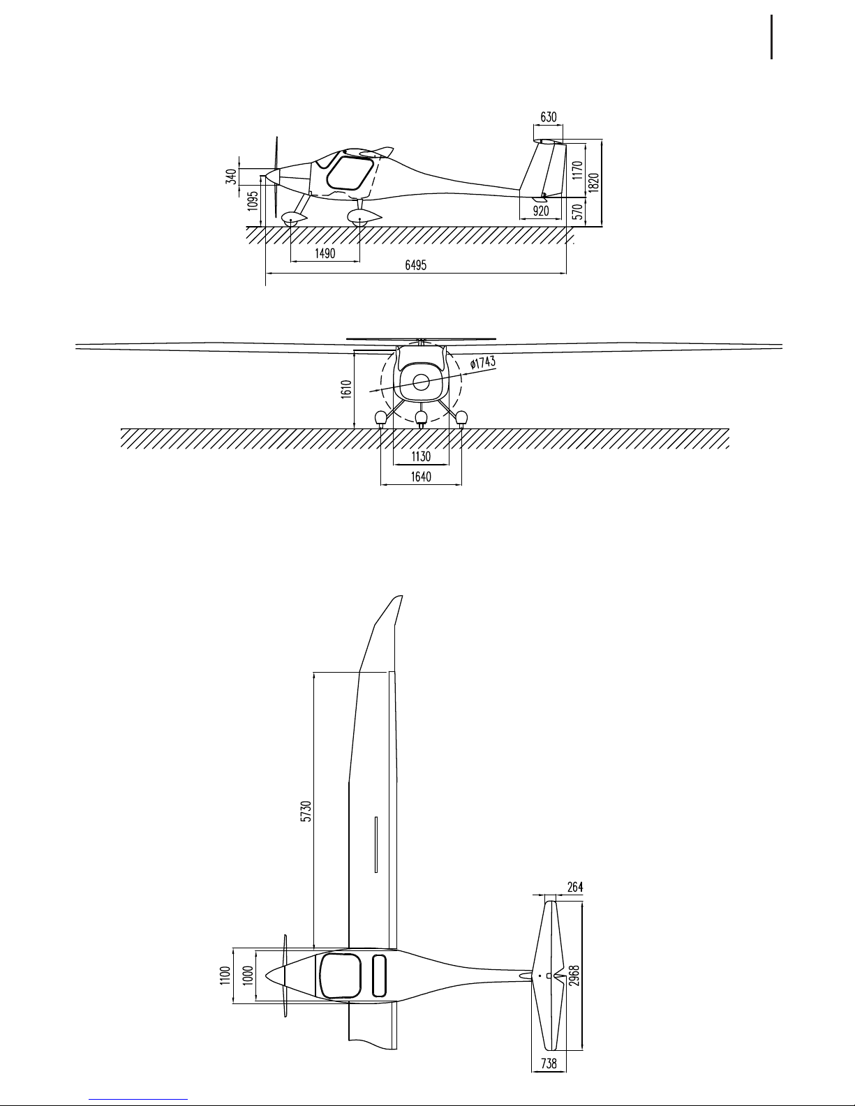
Technical brief
PROPORTIONS Sinus 912 LSA (all models)
wing span 49 ft 1 inch (14.97 m)
length 21 ft 3 inch (6.50 m)
height 6 ft (1.82 m)
wing surface 132 sqft (12.26 m2)
vertical n surface 12 sqft (1.1 m2)
horizontal stabilizer and elevator surface 17.5 sqft (1.63 m2)
aspect ratio 18.3
positive ap deection (down) 9 °, 18 °
negative ap deection (up) 5°
centre of gravity (MAC) 20% - 39%
General
Introduction
This manual contains all information needed for appropriate and safe use of Sinus 912 LSA.
IT IS MANDATORY TO CAREFULLY STUDY THIS MANUAL PRIOR TO USE OF AIRCRAFT
In case of aircraft damage or people injury resulting form disobeying instructions in the manual
PIPISTREL LSA s.r.l. denies all responsibility.
All text, design, layout and graphics are owned by PIPISTREL LSA s.r.l. Therefore this manual and any
of its contents may not be copied or distributed in any manner (electronic, web or printed) without
the prior consent of PIPISTREL LSA s.r.l. unless they are directly related to the operation of our aircraft
by an owner or his appointed maintenance authority.
1-2
Sinus 912 LSA Glider 550 MTOW
www.pipistrel.eu
REV. 3
3-view drawing
General
1-3

Sinus 912 LSA Glider 550 MTOW
www.pipistrel.eu
REV. 3
Powerplant, fuel, oil
Engine manufacturer: ROTAX
Engine type: ROTAX 912 UL (80 HP)
Data below is data relevant for pilot. Consult the original Rotax engine manual for all other details.
The engine
TEMPERATURE °C / ROTAX ENGINE 912 UL 80 HP
cylinder head temp. (CHT); minimum, working, highest 80; 110; 120
max. CHT dierence /
exhaust gas temperature (EGT); normal, max. 650-885; 900
max. EGT dierence 30
cooling uids temperature (WATER); minimum, highest 50; 120
oil temperature (OIL TEMP); minimum, normal, highest 50; 90-110; 140
RPM, PRESSURE 912 UL 80 HP
oil pressure (OIL PRESS); lowest, highest bar (psi)
1.0; 6.0
(14.5; 87.0)
engine revolutions (RPM); on ground recommended 5500
RPM on ground; max. allowable 5800
magneto check at (RPM) 4000
max. single magneto drop (RPM) 300
Fuel and oil
ROTAX ENGINE 912 UL 80 HP
recommended fuel
unleaded super,
grade 87 and
up, no alcohol
content
also approved fuels
leaded* or
AVGAS 100LL*
recommended oil
API SJ SAE
10W-50
oil capacity typical 3 quarts (3 liters) check dipstick
*Engine life is reduced. Should you be forced to used this kind of fuel, change of engine oil every
50 ight hours is crucial. Please consult the manufacturer on which type of oil to use.
IMPORTANT!
Four-stroke engines should only be powered by unleaded fuel, for lead sedimentation inside the engine shortens its life. Provided you are unable to use unleaded fuel, make sure engine oil and the oil
lter are replaced every 50 ight hours.
WARNING! Use of fuel with alcohol content and/or other additives is not permitted.
1-4
General

Sinus 912 LSA Glider 550 MTOW
www.pipistrel.eu
REV. 3
NOTES
To ensure maximum fuel capacity and minimise cross feeding when refuelling, always park the
airplane in a wings level, normal ground attitude.
The visual fuel indicator is equipped with marking for fuel status in US gal and liters. Due to the
wing dihedral the fuel indicator tops before the fuel tank is full. Pilot caution is advised.
Maximum full capacity is indicated only through the fuel ller on the wing, by visual check. At
the same time, verify that the vent tubes remain unobstructed from contamination.
Propeller
Sinus 912 LSA Propeller
Sinus 912 LSA with Rotax 912 UL (80 HP) Pipistrel F2-80
Sinus 912 LSA with Rotax 912 UL (80 HP) Pipistrel Vario
Engine instrument markings
Instrument
Red line
(minimum)
Green arc
(normal)
Yellow arc
(caution)
Red line
(maximum)
Tachometer (RPM)
Oil temperature
Cylinder head temp.
Oil pressure
1600
50°C
(122°F)
/
1.0 bar (14.5 psi)
1600-5500
90-110°C
(194-230°F)
5500-5800110-
140°C
(230-284°F)
110-120°C
(230-248°F)
5800
140
(284°F)
120°C
(248°F)
6.0 bar (87.0 psi)
1-5
General

Sinus 912 LSA Glider 550 MTOW
www.pipistrel.eu
REV. 3
Weights
Sinus 912 LSA weights
WEIGHT 912 LSA 80 HP
standard empty weight 643 lbs (292 kg)
max. takeo weight (MTOM) 1210 lbs (550 kg)
fuel capacity (full) 2 x7.25/13 US gal
fuel capacity (usable) 14.5/24.5 US gal (55/93 L)
max. fuel weight allowable 101/167 lbs (46/76 kg)
maximum useful load 568 lbs (258 kg)
minimum combined cockpit crew weight 119 lbs (54 kg)
maximum combined cockpit crew weight 519 lbs (236 kg)
luggage weight
typically 55 lbs (25
kg), see page p.51
for exact values.
Allowance depends on
conguration, see weight
and balance.
WARNING! Should one of the above-listed values be exceeded, the other MUST be reduced
in order to keep MTOM below 1210 lbs (550 kg). Pay special attention to luggage weight as this
is the only applicable mass on the airframe that has an inuence on centre of gravity. Exceeding
baggage weight limits can shift aircraft’s balance to the point when the ight becomes uncontrollable! More information on baggage allowance can be found in chapter “Weight and Balance”.
Luggage access if via the optional side access door, for larger items the seat folds and the luggage
compartment becomes reachable.
Centre of gravity range
•
Aircraft's safe centre of gravity position ranges between 20% and 39% of mean aerodynamic chord.
•
Centre of gravity point ranges between 243 mm (9.5'') and 408 mm (16.0'') backwards
of datum. Datum is wing's leading edge at the fuselage root.
G-load factors
max. positive wing load: + 4 G
max. negative wing load: – 2 G
These values correspond to ASTM standards for LSA’s. All parts have been tested to a safety factor of
a minimum 1.875, meaning they were subjected to at least a load of 7.5 G
1-6
General

Sinus 912 LSA Glider 550 MTOW
www.pipistrel.eu
REV. 3
Introduction (2-2)
Airspeed limitations (2-2)
Powerplant limitations (2-3)
Weight limits (2-4)
Cockpit crew (2-4)
Centre of gravity limits (2-4)
Load factors (2-5)
Service ceiling and airspeed reductions (2-5)
Manoeuvre limits (2-5)
Kinds of operations (2-6)
Minimum equipment list (2-6)
Other restrictions (2-7)
Placards (2-8)
2 Limitations
Limitations
2-1

Sinus 912 LSA Glider 550 MTOW
www.pipistrel.eu
REV. 3
Airspeed limitations
Velocity
IAS
[kts (km/h)]
Remarks
VS
Stall speed
Clean
40 (74)
Stall speed ap up.
VS0
Stall speed
Landing conguration
34 (64)
Stall speed aps full.
VFE
Max. velocity aps
extended
70 (130)
Do not exceed this speed with aps
extended (+9, +18 degrees).
VA
Design maneuvering
speed
76 (141)
Do not make full or abrupt control movements above this speed.
VNE
Velocity never to be
exceeded
120 (222)
Never exceed this speed in any operation.
VNE is dened as TAS above 3000 ft MSL,
see »Service ceiling and airspeed reductions«.
VNO
Maximum safe velocity
in rough air
76 (141)
Maximum speed in turbulent air.
VAE
Maximum velocity of
airbrake extension
86 (160)
Do not extend spoilers above this
speed.
VES
Maximum velocity for
engine restart in ight
50 (90)
Applicable only for the Vario feathering
propeller version! Do not restart the engine in ight beyond this speed.
Airspeed indicator markings
MARKING IAS [kts (km/h)] Denition
White band
34 -70
(64 - 130)
Full Flap Operating Range. Lower limit is the maximum
weight VS0 in landing conguration. Upper limit is maximum speed permitted with aps extended.
Green band
40 -76
(74 - 141)
Normal Operating Range Lower end is maximum weight
VS1 at most forward C.G. with aps retracted. Upper limit is
maximum structural cruising speed.
Yellow band
76 - 120
(141 - 222)
Manoeuvre the aircraft with caution in calm air only.
Red line
120
(222)
Maximum speed for all operations
Blue line
62 (115)
Best climb rate speed (VY)
Introduction
This section includes operating limitations, instrument markings and basic placards necessary for
the safe operation of the airplane, it’s engine, standard system and standard equipment.
The limitations included in this section have been approved. Observance of these operating limitations is required by Federal Aviation Regulations.
Sinus 912 LSA is approved under ASTM standard F2564.
Limitations
2-2

Sinus 912 LSA Glider 550 MTOW
www.pipistrel.eu
REV. 3
Limitations
Powerplant limitations
Engine manufacturer: ROTAX
Engine type: ROTAX 912 UL (80 HP)
Data below is data relevant for the pilot. Consult the original Rotax engine manual for all other details.
The engine
TEMPERATURE °C / ROTAX ENGINE 912 UL 80 HP
cylinder head temp. (CHT); minimum, working, highest 80; 110; 120
max. CHT dierence /
exhaust gas temperature (EGT); normal, max. 650-885; 900
max. EGT dierence 30
cooling uids temperature (WATER); minimum, highest 50; 120
oil temperature (OIL TEMP); minimum, normal, highest 50; 90-110; 140
RPM, PRESSURE 912 UL 80 HP
oil pressure (OIL PRESS); lowest, highest 1.0; 6.0
engine revolutions (RPM); on ground recommended 5500
RPM on ground; max. allowable 5800
ignition check at (RPM) 4000
max. single ignition drop (RPM) 300
Fuel and oil
ROTAX ENGINE 912 UL 80 HP
recommended fuel
unleaded super,
grade 87 and
up, no alcohol
content
also approved fuels
leaded* or
AVGAS 100LL*
recommended oil
API SJ SAE
10W-50
*Shorter maintenance intervals are imposed. Should you be forced to used this kind of fuel,
change of engine oil every 50 ight hours is crucial. Please consult the manufacturer on which
type of oil to use.
IMPORTANT!
Four-stroke engines should only be powered by unleaded fuel, for lead sedimentation inside the engine shortens its life. Provided you are unable to use unleaded fuel, make sure engine oil and the oil
lter are replaced every 50 ight hours.
WARNING! Use of fuel with alcohol content and/or other additives is not permitted.
2-3

Sinus 912 LSA Glider 550 MTOW
www.pipistrel.eu
REV. 3
Limitations
Propeller
Sinus SW Propeller
Sinus 912 LSA with Rotax 912 UL (80 HP)
Pipistrel F2-80 - diameter 63 inch (1620 mm)
Pipistrel Vario feathering propeller 63 inch (1620mm)
Engine instrument markings
Instrument
Red line
(minimum)
Green arc
(normal)
Yellow arc
(caution)
Red line
(maximum)
Tachometer (RPM)
Oil temperature
Cylinder head temp.
Oil pressure
1600
50°C
(122°F)
/
1.0 bar (14.5 psi)
1600-5500
90-110°C
(194-230°F)
5500-5800
110-130°C
(230-266°F)
110-120°C
(230-248°F)
5800
130
(266°F)
120°C
(248°F)
6.0 bar (87.0 psi)
Weights
Sinus 912 LSA weights
WEIGHT 912 LSA 80 LSA
max. takeo weight (MTOM) 1210 lbs (550 kg)
minimum combined cockpit crew weight 119 lbs (54 kg)
maximum combined cockpit crew weight 519 lbs (236 kg)
baggage area
85 lbs absolute limit, where the load is to
be distributed and loading not exceed
8 pounds per square foot. Always verify
baggage allowance with a
Centre of Gravity calculation!
WARNING! Should one of the above-listed values be exceeded, other MUST be reduced in
order to keep MTOM below 1210 lbs (550 kg). Pay special attention to luggage weight as this is
the only applicable mass on the airframe that has an inuence on centre of gravity. Exceeding
baggage weight limits can shift aircraft’s balance to the point when the ight becomes uncontrollable! More information on baggage allowance can be found in chapter “Weight and Balance”.
Centre of gravity range
•
Centre of gravity point ranges between 210 mm and 374 mm (8.3 inch and 14.7 inch)
aft of datum. Datum is wing's leading edge at fuselage root.
2-4

Sinus 912 LSA Glider 550 MTOW
www.pipistrel.eu
REV. 3
Limitations
G-load factors
max. positive wing load: + 4 G
max. negative wing load: – 2 G
These values correspond to ASTM standards for LSA’s. All parts have been tested to a safety factor of
a minimum of 1.875, meaning they were subjected to at least a load of 7.5 G
Service ceiling and airspeed reductions
Service ceiling is not limited, however due to the glider-type construction and aerodynamics, the
VNE must be regarded as TAS when ying higher than 9000 ft. VNE limits are also provided on the
cockpit placard.
WARNING! Above pressure altitude of 3000 ft, the VNE MUST be treated as True
Air Speed (TAS). Indicated Air Speed (IAS) MUST be reduced accordingly! Table with
IAS, TAS relation for the VNE of 120 kts is provided below:
Altitude 0 ft 6000 ft 12000 ft 18000 ft
TAS 120 kts 120 kts 120 kts 120 kts
VNE
(IAS)
120 kts 111 kts 100 kts 92 kts
Maneuver limits
Sinus 912 LSA is approved under ASTM standard F2564 and is intended for recreational
and instructional ight operations. In the acquisition of various pilot certicates certain
maneuvers are required and these maneuvers are permitted in this airplane.
Following NON Aerobatic manoeuvres are permitted as dened:
•
Power-on and -o stalls not below 1500 feet (450 meters) above ground level.
•
Power on and o lazy eights not below 1500 feet (450 meters) above ground level,
entry speed 90 kts
•
Steep turns with initial speed of 80 kts.
•
Chandelle maneuvers not below 500 feet (150 meters) above ground level, entry
speed 105 kts.
•
Spin initiation and recovery (at most 180° in actual spinning manoeuvre).
WARNING! Aerobatic maneuvers, including full developed spins, are prohibited.
CAUTION! Intentional ying with both cabin doors open is prohibited. Flying with one door
open in ight is approved with airspeeds up to 60 kts, ying with one door removed is approved
without changes to the limitations of the normal operational envelope.
2-5

Sinus 912 LSA Glider 550 MTOW
www.pipistrel.eu
REV. 3
Kinds of operations
Sinus 912 LSA is approved for DAY - NIGHT - VFR operations only. Flight
into known icing conditions is prohibited.
WARNING! Should you nd water drops on the airframe during preight check-up at
temperatures close to freezing, you may expect icing to appear in ight. Optional airbrakes are
especially prone to icing under such circumstances. As water may accumulate underneath the
top plate(s), spoilers may freeze to the wing surface. Should this occur, you will most denitely be
unable to extend spoilers before the ice melts. Therefore, ying under circumstances mentioned
above, it is recommended to extend and retract the spoilers in ight frequently to prevent its surface freezing to the airframe.
Minimum equipment list (DAY - VFR)
• Placards, checklist
• Airspeed indicator (functional), Altimeter (functional), Compass (functional)
• Tachometer (RPM), EGT indication (functional), CHT indication (functional), OIL temp. indication (functional), OIL press. indication (functional)
• 12 V Main battery (functional), Alternator (functional) Safety belts (2x), Visual fuel indication
(L/R functional), Fuel shut-o valves (L/R, functional)
Minimum equipment list (NIGHT - VFR)
In addition to the MEL for DAY - VFR:
• Articial horizon (functional)
• NAV/STROBE/LDG lights (functional), Cockpit light (functional)
• Stand-by battery (12 V), VHF COM/TRANSPONDER/ALTITUDE ENCODER/GPS - as required for
the operation
• Night operations are only allowed if the aircraft complies with your local regulations and
you hold the required pilot endorsements.
Fuel limitations
FUEL Sinus 912 LSA
fuel capacity (full standard tanks) 2 x 8 US gal (2x30 L)
fuel capacity (full long range tanks) 2 x 13 US gal (2x50)
fuel capacity (usable - all ight conditions, standard/long range)
14.5 / 24.5 US gal
55 / 93 L
unusable fuel
1.5 US gal
(0.75 US gal per tank)
max. fuel weight allowable 167 lbs (76 kg)
2-6
Limitations

Sinus 912 LSA Glider 550 MTOW
www.pipistrel.eu
REV. 3
WARNING! Takeo is prohibited if either visual fuel indicator indicates in the red area (less
than 1.3 US gal) or when unsure about the fuel quantity on board.
NOTES
To ensure maximum fuel capacity and minimise cross feeding when refuelling, always park the
airplane in a wings level, normal ground attitude.
The visual fuel indicator is equipped with marking for fuel status in US gal and liters. Due to the
wing dihedral the fuel indicator tops before the fuel tank is full. Pilot caution is advised.
Maximum full capacity is indicated only through the fuel ller on the wing, by visual check. At
the same time, verify that the vent tubes remain unobstructed from contamination.
Other restrictions
Due to ight safety reasons it is forbidden to:
•
y in heavy rainfalls;
•
y during thunderstorm activity;
•
y in a blizzard;
•
y according to instrumental ight rules (IFR) or attempt to y in zero visibility conditions (IMC);
•
y when outside air temperature (OAT) reaches 50°C (122°F) or higher;
•
perform aerobatic ying;
•
take o and land with aps retracted or set to negative (-5°) position
(landing with -5° is permitted only in case of very strong winds,
but is not to be performed as a normal procedure)
•
take o with airbrakes extended.
•
the 12 Volt power outlet is not approved to supply power to ight-critical communication or navigation devices.
2-7
Limitations
Sinus 912 LSA Glider 550 MTOW
www.pipistrel.eu
REV. 3
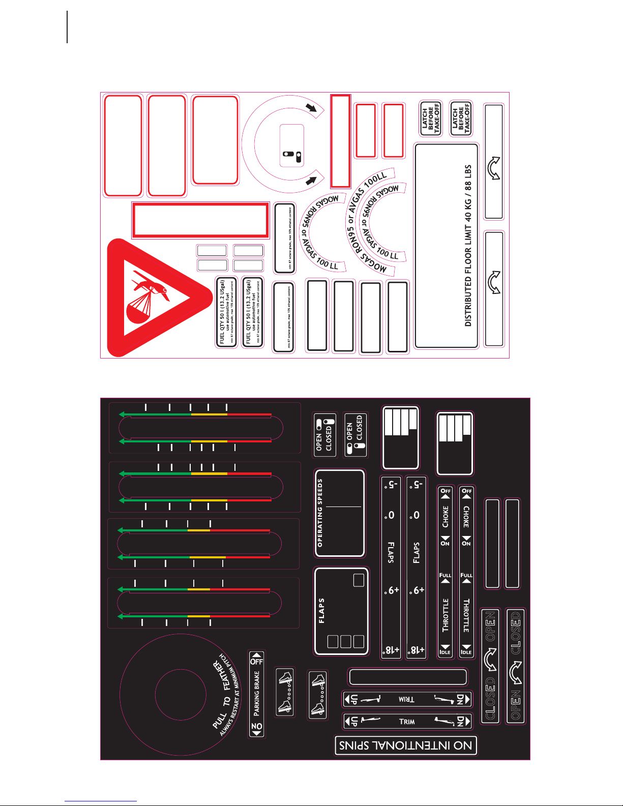
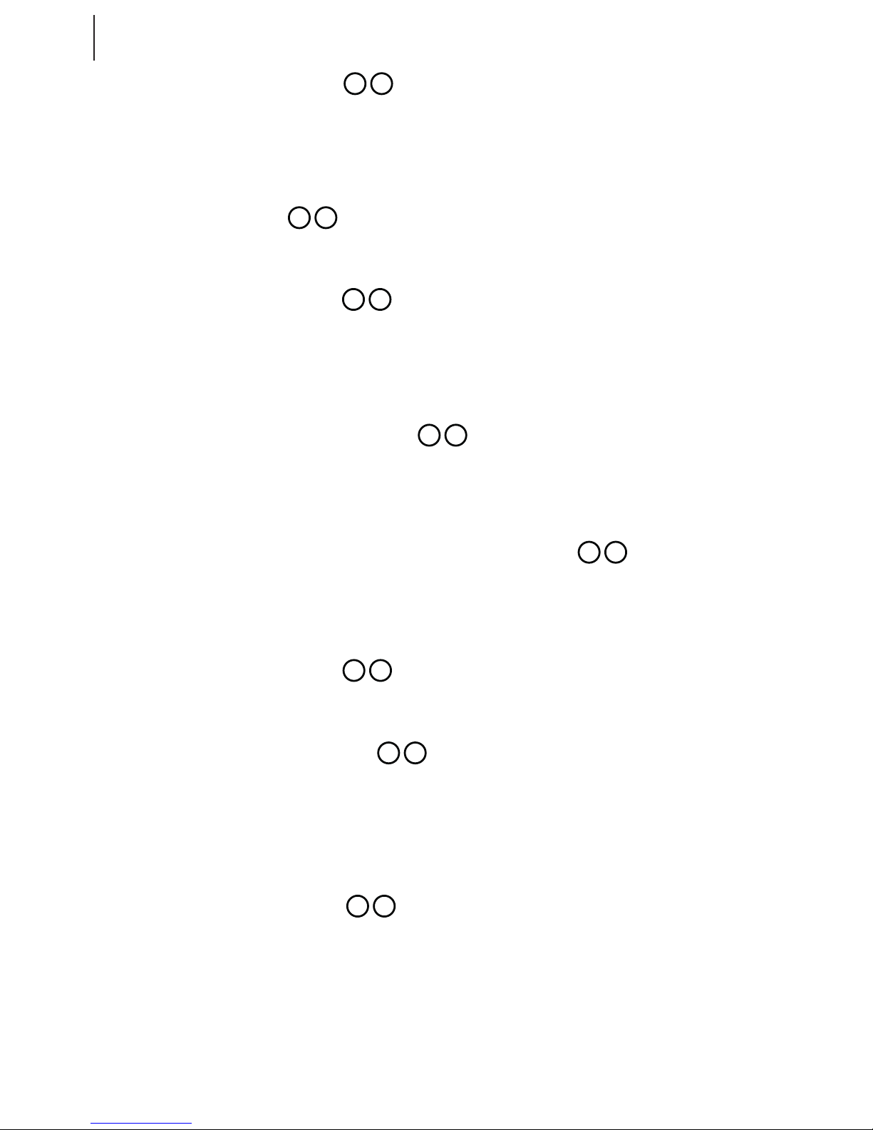
Placards
This aircraft is approved to fly in visual meteorological conditions (VMC) only
and flights in instrumental meteorological conditions (IMC) are prohibited!
This aircraft is equipped
with a rocket powered
ballistic rescue system.
PASSENGER WARNING
This aircraft was manufactured in
accordance with Light Sport Aircraft
airworthiness standards and does not
conform to standard category
airworthiness requirements
NO STEP
3,5 l OIL
Refer to ROTAX manual
NO STEP
80 % ANTIFREEZE
+ 20 % WATER
ROCKET GAS
EXHAUST
ATTENTION!
ROCKET INSIDE
MAX 1.8 bar
MAX 26 psi
MAX 1.2 bar
MAX 18 psi
MAX 0.8 bar
MAX 12 psi
MAX 1.8 bar
MAX 26 psi
OPEN
CLOSED
D
R
R
A
E
I
T
N
A
V
W
A
/
L
L
V
E
E
U
F
C
L
N
O
E
S
P
E
O
DANGER
EXPLOSIVE
EGRESS
EAW
MTOW
CREW WT
LUGGAGE WT
lbs
1212 lbs
min.121 lbs
55 lbs
FUEL QTY 30 l (7.9 USgal)
use automotive fuel
This aircraft is equipped
with a rocket powered
ballistic rescue system.
EAW
MTOW
CREW WT
LUGGAGE WT
kg
550 kg
min. 55 kg
25 kg
FUEL QTY 30 l (7.9 USgal)
use automotive fuel
USgal
Liter
USgal
Liter
Sv50 Sv50
1
3
4
5
6
2
30
5
10
15
20
1
3
4
5
6
2
5
10
15
20
30
5
10
15
20
USgal
Liter
USgal
Liter
1
4
6
2
Sv30 Sv30
5
10
15
20
5
10
15
20
1
4
6
2
PULL FOR PARACHUTE
DEPLOYMENT
WARNING
ROCKET FOR PARACHUTE
DEPLOYMENT INSIDE
+18
+9
0
34-60 kts
38-70 kts
40-86 kts, then
-5
Respect limits
from POH!
VSO
VS1
VFEVAVNO
34 kts
40 kts
70 kts
76 kts
76 kts
VNE
120 kts
Respect limits
from POH!
OPEN CLOSED
R L
R MIC L
OPEN CLOSED
OPEN CLOSED
OPEN CLOSED
HEADSET
SEE AIRCRAFT FLIGHT MANUAL FOR
BAGGAGE LIMITATIONS AND WEIGHT
AND BALANCE INFORMATION
2-8
Limitations

Sinus 912 LSA Glider 550 MTOW
www.pipistrel.eu
REV. 3
Introduction (3-2)
Stall recovery (3-2)
Spin recovery (3-2)
Engine failure (3-3)
Emergency landing /
Landing out (3-3)
Engine re (3-3)
Smoke in cockpit (3-4)
Carburetor icing (3-4)
Electrical system failure (3-5)
Flutter (3-5)
Exceeding VNE (3-5)
Ditching (3-5)
Icing/Pneumatic failure
(3-5)
3 Emergency procedures
Emergency procedures
3-1

Sinus 912 LSA Glider 550 MTOW
www.pipistrel.eu
REV. 3
Emergency procedures
Introduction
This sections provides information for coping with emergencies that may occur. Emergencies caused
by airplane or engine malfunctions are extremely rare if proper preight inspections and maintenance are practiced. Enroute weather emergencies can be minimized or eliminated by careful ight
planning and good judgment when unexpected weather is encountered. In any emergency, the
most important task is continued control of the airplane and manoeuvring to execute a successful
landing.
Stall recovery
First reduce angle of attack by pushing the control stick forward, then
1. Add full power (throttle lever in full forward position).
2. Resume horizontal ight.
Spin recovery
Sinus 912 LSA is constructed in such manner that it is dicult to be own into a spin, and even so
only at aft centre of gravity positions. However, once spinning, intentionally or unintentionally, react
as follows:
1. Set throttle to idle (lever in full back position).
2. Apply full rudder deection in the direction opposite the spin.
3. Lower the nose towards the ground to build speed (stick forward).
4. As the aircraft stops spinning neutralise rudder deection.
5. Slowly pull up and regain horizontal ight.
Sinus 912 LSA tends to re-establish normal ight by itself usually after having spinned for a mere
45°-90°.
WARNING! Keep the control stick centred along its lateral axis (no aileron deections
throughout the recovery phase! Do not attempt to stop the aircraft from spinning using ailerons
instead of rudder!
WARNING! After having stopped spinning, recovering from the dive must be performed
using gentle stick movements (pull), rather than overstressing the aircraft.
However, VNE must not be exceeded during this manoeuvre.
When the aircraft is wings-level and ies horizontally, add throttle and resume normal ight.
3-2

Sinus 912 LSA Glider 550 MTOW
www.pipistrel.eu
REV. 3
Engine failure
Engine failure during takeo
Ensure proper airspeed rst (55 kts) and land the aircraft on runway heading, avoiding eventual obstacles in your way. Shut both fuel valves and set master switch to OFF position (key full left).
WARNING! DO NOT CHANGE COURSE OR MAKE TURNS IF THIS IS NOT OF VITAL NECESSITY!
After having landed safely, ensure protection of aircraft and vacate the runway as soon as possible to keep the runway clear for arriving and departing trac.
Rough engine operation or engine failure in ight
First ensure proper airspeed (64 kts), then start analyzing terrain underneath and choose the most
appropriate runway or site for landing out.
Provided the engine failed aloft, react as follows:
Make sure the master switch is in the ON position, magneto switches both set to ON and both fuel
valves OPEN. Attempt to restart the engine. If unsuccessful, begin with the landing out procedure
immediately.
Emergency landing / Landing o airport
1. Shut both fuel valves.
2. Master switch OFF.
3. Approach and land with extreme caution, maintaining normal airspeeds.
4. After having landed leave the aircraft immediately.
The landing o airport manoeuvre MUST be preformed with regard to all normal ight parameters.
Engine re
Engine re on ground
This phenomenon is very rare in the eld of sport aviation. However, if an engine re on ground occurs, react as follows:
1. Shut both fuel valves.
2. Come to a full-stop, engage starter and set throttle to full power (lever full forward).
3. Disconnect the battery from the circuit (pull battery disc. ring on the switch column)
4. Master switch OFF immediately after the engine has stopped.
5. Abandon the aircraft and start extinguishing the re.
WARNING! After the re has been extinguished DO NOT attempt to restart the engine.
Emergency procedures
3-3

Sinus 912 LSA Glider 550 MTOW
www.pipistrel.eu
REV. 3
Engine re in ight
1. Shut both fuel valves and set magnetos to OFF.
2. Set full power (throttle lever in full forward position).
3. Disconnect the battery from the circuit (pull battery disc. ring on the switch column)
3b. Keep avionics ON and master ON as required, on approach set both OFF.
4. Set ventilation for adequate breathing. Keep in mind that oxygen intensies re.
5. Perform side-slip (crab) manoeuvre in direction opposite the re.
6. Perform emergency landing out procedure.
Smoke in cockpit
Smoke in cockpit is usually a consequence of electrical wiring malfunction. As it is most denitely
caused by a short circuit it is required that the pilot reacts as follows:
1. Master switch to I (key in central position). This enables unobstructed engine operation while
at the same time disconnects all other electrical devices from the circuit. Verify that the 12 V and
optional Pitot heat are OFF as well.
2. Disconnect the battery from the circuit (pull battery disconnection ring on the instrument
panel’s switch column).
3. Land as soon as possible.
In case you have trouble breathing or the visibility out of the cockpit has degraded severely due to
the smoke, open the cabin door and leave it hanging freely. Flying with the door open, do not, under
any circumstances exceed 60 kts (110 km/h).
Carburetor icing
First noticeable signs of carburetor icing are rough engine running and gradual loss of power.
Carburetor icing may occur even at temperatures as high as 50°F (10°C) , provided the air humidity is
increased.
The carburetor air-intake in the Sinus 912 LSA is preheated, running over the water cooling radiator
before entering the carburetors. Therefore the possibility of carburetor icing is minuet.
Should you be suspecting carburetor icing to take place, descend immediately into warmer and/
or less humid air!
In case of complete power loss perform emergency landing procedure.
Electrical system failure
The engine will continue to function due to the onboard alternator and battery. In case of battery failure, be aware that the engine can keep running, however a re-start will not be possible.
In event of alternator failure, the battery will support the onboard avionics. In event of double
power source failure, use analogue on-board instruments and land normally.
3-4
Emergency procedures

Sinus 912 LSA Glider 550 MTOW
www.pipistrel.eu
REV. 3
Flutter
Flutter is dened as the oscillation of control surfaces. It is most cases caused by abrupt control deections at speeds close or in excess of VNE. As it occurs, the ailerons, elevator or even the whole
aircraft start to vibrate violently.
Should utter occur, increase angle of attack (pull stick back) and reduce throttle
immediately in order to reduce speed and increase load (damping) on the structure.
WARNING! Fluttering of ailerons or tail surfaces may cause permanent structural damage
and/or inability to control the aircraft. After having landed safely, the aircraft MUST undergo a
series of check-ups performed by authorised service personnel to verify airworthiness.
Exceeding VNE
Should the VNE be exceeded, reduce airspeed slowly and continue ying using gentle control
deections. Land safely as soon as possible and have the aircraft veried for airworthiness by
authorised service personnel.
Ditching
Should you be forced to land in a body of water, use the same emergency procedure as above for
the “Emergency landing / Landing out” case. In addition, make sure to open both doors fully before hitting the water, disconnect the battery from the circuit (pull ring on electrical panel). Touch
the water with the slowest possible speed, possibly from a high-are situation.
Icing/Pneumatic instrument failures
Turn back or change altitude to exit icing conditions. Consider lateral or vertical path reversal to
return to last “known good” ight conditions. Maintain VFR ight!
Set cabin heating ON and Pitot heat (optional) ON. Watch for signs of icing on the pitot tube. In
case of pneumatic instrument failures, use the GPS (optional) information to reference to approximate ground speed. Plan the landing at the nearest airport, or a suitable o airport landing
site in case of an extremely rapid ice build-up.
Maneuverer the aeroplane gently and leave the wing aps retracted. When ice is built up at the
horizontal stabilizer, the change of pitching moment due to aps extension may result of loss of
elevator control. Approach at elevated speeds (70 kts, also if using the GPS as a reference).
WARNING! Failure to act quickly may result in an unrecoverable icing encounter.
3-5
Emergency procedures

Sinus 912 LSA Glider 550 MTOW
www.pipistrel.eu
REV. 3
This page is intentionally left blank.
3-6

Sinus 912 LSA Glider 550 MTOW
www.pipistrel.eu
REV. 3
Daily inspection (4-2)
Preight inspection (4-2)
Normal procedures and
recommended speeds (4-5)
4 Normal procedures
Normal procedures
4-1

Sinus 912 LSA Glider 550 MTOW
www.pipistrel.eu
REV. 3
Normal procedures
Daily Inspection
The daily check-up matches the preight inspection.
Preight inspection
WARNING! Every single inspection mentioned in this chapter must be performed prior to
EVERY FLIGHT, regardless of when the previous ight took place!
The person responsible for the preight inspection is the pilot, who is required to perform the check-up in the utmost thorough and precise manner.
Provided the status of any of the parts and/or operations does not comply with conditions stated
in this chapter, the damage MUST be repaired prior to engine start-up. Disobeying this instructions may result in serious further damage to the plane and crew, including injury and loss of life!
Schematic of preight inspection
1 Engine, engine cover 8 Right wing - trailing edge 15 Hor. tail surfaces (left)
2 Gascolator 9 Right air brake 16 Fuselage, continued (left)
3 Spinner, Nose wheel 10 Fuselage (RH side) 17 Fuselage (LH side)
4 Propeller 11 Fuselage, continued (right) 18 Left air brake
5 Undercarriage, RH wheel 12 Hor. tail surfaces (right) 19 Left wing - trailing edge
6 Right wing - leading edge 13 Vert. tail surfaces (right) 20 Left wingtip, lights
7 Right wingtip, lights 14 Vert. tail surfaces (left) 21 Left wing - leading edge
22 Undercarriage, LH wheel
4-2
12
1
2
3
4
5
6
7
8
9
10
11
13
14
15
16
17
18
19
20
21
22

Sinus 912 LSA Glider 550 MTOW
www.pipistrel.eu
REV. 3
Engine, engine cover
Cooling uid level: half way to the top
Oil quantity: within designated limits
Throttle, choke and oil pump wires: no mechanical damage, smooth and unobstructed movement
Radiators and hoses: no mechanical damage and/or leakage, air lters clean and intact
Exhaust pipes and muer: rmly in position, no cracks, springs intact and in position, rubber
dumpers intact
Fuel and/or oil leakage: no uid on hoses, engine housing or engine cover
Reduction gearbox: check for eventual oil leakage, all bolts and plugs attached rmly
Fasteners and engine cover screws: tightened, engine cover undamaged
Gascolator
Drain approximately 1 cup of fuel and check for contamination.
Spinner
Spinner: no mechanical damage (e.g. cracks, impact spots), screws tight
Bolts and nuts: secured
Nose wheel: grab aircraft’s propeller and push it towards the ground to verify proper nose wheel
suspension operation. Then lift the nose wheel o the ground and check for nose leg strut free play.
Bolts: fastened
Tire: no cracks, adequate pressure
Wheel fairing: undamaged, rmly attached, clean (e.g. no mud or grass on the inside)
Propeller
Hub and blades: no mechanical damage (e.g. cracks), both immaculately clean
Bolts and nuts: secured
Feathering mechanism (optional): smooth travel of propeller pitch, adequate spring tension
Undercarriage, wheels
Bolts: fastened
Landing gear strut: no mechanical damage (e.g. cracks), clean
Wheel: no mechanical damage (e.g. cracks), clean
Wheel axle and nut: fastened
Oil line (hydraulic brakes): no mechanical damage and/or leakage
Tire: no cracks, adequate pressure
Wheel fairing: undamaged, rmly attached, clean (e.g. no mud or grass on the inside)
1
2
3
4
5
Normal procedures
22
4-3
Sinus 912 LSA Glider 550 MTOW
www.pipistrel.eu
REV. 3
Wings’ leading edge
Surface condition: pristine, no cracks, impact spots, no paint and/or edge separations
Pitot tube: rmly attached, no mechanical damage or bending. Remove protection cover and make
sure it is not blocked or full of water.
Wing drain holes: make sure they are not blocked and clean accordingly.
Wingtip, lights
Surface condition: pristine, no cracks, impact spots or bumps, no paint separations
Wings’ trailing edge
Surface condition: pristine, no cracks, impact spots, no paint and/or edge separations
Mylar sealing tape between wing and aileron: undamaged and in position
Aileron: pristine surface, no cracks and/or impact spots, no paint abnormalities and edge separa-
tions, no vertical or horizontal free play, smooth and unobstructed deections
Airbrakes, fuel reservoir cap
Air brakes: rm, smooth, equal and unobstructed extension, tightly tted when retracted, springs
sti and intact.
Fuel reservoir cap: fastened. Make sure the vent pipe is completely clean.
Fuselage, antenna, rescue parachute cover
Self-adhesive tape: in position, no separations
Controls’ cap, antenna: rmly attached
Station 17 - optional side access door to the cargo compartment: closed and locked
Fuselage, continued
Surface condition: pristine, no cracks, impact spots or bumps, no paint separations
Horizontal tail surfaces
Surface condition: pristine, no cracks, impact spots or bumps, no paint and/or edge separations
Hinges: no free play in any direction
Central securing screw on top of the horizontal stabilizer: fastened and secured
Self-adhesive tape covering the gap between horizontal and vertical tail surfaces: in position
Elevator: smooth and unobstructed up-down movement, no side-to-side free play
Vertical tail surfaces
Vertical n bottom part: no cracks, impact spots or paint separations along main chord
Surface condition: pristine, no cracks, impact spots or bumps, no paint separations
Hinges: no free play in any direction
Rudder cable endings: intact, bolts in position
CAUTION! Preight inspection should be performed following stations 1 through 22!
7
20
8
19
9
18
10
17
11
16
12
15
13
14
Normal procedures
6 21
4-4

Sinus 912 LSA Glider 550 MTOW
www.pipistrel.eu
REV. 3
Normal procedures
Cockpit preight inspection
Instrument panel and instruments: checked
Fuses: checked
Battery disconnection lever: in position for battery operation (lever deected towards the rewall)
Master switch OFF (key in full left position): no control lights and/or electronic instrument activity
Master switch ON (key in full right position): control lights and electronic instrument active
Make sure you have set all instruments to correct initial setting.
Main wing spars and connectors: no visible abnormalities of metal parts, spars, pins and bolts; all
bolts and nuts in position and tightened
Fuel hoses, pitot-static lines and electrical cables: correctly connected and in position
Transparent plastic providing visual fuel quantity monitoring: clean with no cracks
Safety harness: undamaged, verify unobstructed harness opening; fastening points intact
Doors and windshield: perfect closing at all three points, smooth opening, hinges rmly attached;
immaculately clean with no cracks.
Flap handle: button spring rm, locking mechanism working properly, smooth movement along full
deections, no free play or visible damage.
Airbrakes handle: full-up and locked
Radio wiring: test the switches, check connectors and headset, perform radio check
Battery (some models): rmly in position, check water level (if not dry version), joints clean with
wires connected
Emergency parachute release handle (optional): safety pin removed.
Make sure unobstructed access is provided.
Normal procedures
and recommended speeds
To enter the cabin rst lift the door all the way to the bottom wing surface. The silver knob will grab
and secure the door in position. Sit onto the cabin’s edge and support your body by placing hands
onto this same cabin edge. Drag yourself into the seat lifting rst only one leg over the stick for best
position. Immediately after having sat into the seat, check rudder pedals’ position to suit your size
and needs. To lower the door DO NOT attempt to grab and pull door’s handle but gently pull the silver knob instead. To close the door securely, rotate the handle so that it locks and verify that all three
closing points are secured.
Fasten the safety harnesses according to your size.
Adjust the rudder pedals according to your required legroom. The aircraft is equipped with in-ight
adjustable rudder pedals, which adjust as follows:
Sit inside the cockpit and release the pressure o the pedals. Pull the black knob in front of the control stick to bring the pedals closer to you. To move the pedals further away, rst release the pressure
of the pedals, then pull on the knob slightly (this will release the lock in the mechanism). Now push
the pedals forward using with your feet, while keeping the black adjustment knob in your hand.
WARNING! The safety harness must hold you in your seat securely. This is especially impor-
tant when ying in rough air, as otherwise you may bump into the tubes and/or spars overhead.
Make sure you tighten the bottom straps rst, then shoulder straps.
4-5

Sinus 912 LSA Glider 550 MTOW
www.pipistrel.eu
REV. 3
Engine start-up
Before engine start-up
CAUTION! To ensure proper and safe use of aircraft it is essential for one to familiarise your-
self with engine’s limitations and engine manufacturer’s safety warnings. Before engine start-up
make sure the area in front of the aircraft is clear. It is recommended to start-up the engine with
aircraft’s nose pointing against the wind.
Make sure the fuel quantity is sucient for the planned ight duration.
Make sure the pitot tube is uncovered and rescue parachute safety pin removed.
Engage wheel brakes. If equipped with the parking brake, engage parking brake.
Engine start-up
Make sure both fuel valves are open and master switch in OFF position (key full left).
Should the engine be cold, apply choke (lever full back).
Set master switch ON (key in full right position). Set both magneto switches ON. Avionics OFF.
Engage engine starter and keep it engaged until the engine starts.
Set throttle to 2500 RPM.
Slide the choke lever forward gradually.
CAUTION! When the engine is very cold, the engine may refuse to start. Should this occur,
move the choke handle fully backwards and hold it there for some 20 seconds to make mixture
richer.
Engine warm-up procedure
The engine should be warmed-up at 2500 RPM up to the point working temperature is reached.
Warming-up the engine you should:
1 Point aircraft’s nose into the wind.
2 Verify the engine temperature ranges within operational limits.
CAUTION! Avoid engine warm-up at idle throttle as this causes the spark plugs to turn dirty
and the engine to overheat.
With wheel brakes engaged and control stick in full back position, rst set engine power to 4000
RPM in order to perform the ignition check. Set the ignition switches OFF and back ON one by one to
verify RPM drop of not more than 300 RPM.
When the ignition check has been completed, add full power (throttle lever full forward) and
monitor engine’s RPM. Make sure they range between maximum recommended and maximum
allowable RPM limits.
Note that engine does not reach 5800 RPM on ground. Engines are factory set to reach maximum
ground RPM of 5300 - 5500 at sea level at 68° F. Maximum ground RPM may vary depending on the
season and service elevation.
CAUTION! Should engine’s RPM be lower than the recommended on ground amount (min.
5100 RPM) or in excess of maximum allowable RPM on ground (5800) during this manoeuvre,
check engine and wiring for correct installation.
Normal procedures
4-6

Sinus 912 LSA Glider 550 MTOW
www.pipistrel.eu
REV. 3
Taxi
Release parking brake if tted. Taxing technique does not dier from other aircraft equipped with a
steerable nose wheel. Prior to taxiing it is essential to check wheel brakes for proper braking action.
In the case you expect o taxi a long way, take engine warm-up time into account and begin taxiing
immediately after engine start-up. Warm-up the engine during taxiing not to cause engine overheating because of prolonged ground operation.
Holding point
Make sure the temperatures at full power range are within operational limits.
Make sure the safety harnesses are fastened and doors closed and secured at all three closing points.
Set aps to 2
nd
position (ap handle full up).
Power idle.
CAUTION! Should the engine start to overheat because of long taxi and holding, shut down
the engine and wait for the engine temperatures drop to reasonable values. If possible, point
the aircraft’s nose into the wind. This will provide radiators with airow to cool down the engine
faster.
Take-o and initial climb
Before lining-up verify the following:
Parking brake (if applicable): disengaged (full forward)
Air brakes (if applicable): retracted and secured
Fuel valves: fully open
Fuel quantity: sucient
Safety harnesses: fastened
Cabin doors: closed securely
Trim handle: in neutral position or slightly forward
Flap handle: 2
nd
position (ap handle full up)
Runway: clear
Release brakes, line up and apply full power.
Verify engine for sucient RPM at full throttle (min 5100 RPM).
CAUTION! Keep adding power gradually.
WARNING! Should engine RPM not reach more than 5000 RPM when at full throttle, ABORT
TAKE-OFF IMMEDIATELY, come to a standstill and verify that the propeller is at minimum pitch
setting .
Start the takeo roll pulling the control stick one third backward and lift the nose wheel o the
ground as you accelerate. Reaching 40-43 kts, gently pull on the stick to get the aircraft airborne.
CAUTION! Crosswind (max 15 kts) takeo should be performed with the control stick pointed
into the wind. Special attention should be paid to maintaining runway heading!
Normal procedures
4-7

Sinus 912 LSA Glider 550 MTOW
www.pipistrel.eu
REV. 3
Normal procedures
Initial climb
When airborne, engage brakes momentarily to prevent in-ight wheel spinning.
Accelerate at full power and later maintain proper climbing speed.
As you reach 50 kts (90 km/h) at above 150 ft (50 m), set aps to 1st stage, reaching 60 kts (110 km/h)
at 300 ft (100 m) set aps to neutral position. Reduce RPM by 10% or below 5500 RPM and continue
climbing at 70 kts (130 km/h).
Adjust the trim to neutralize the stick force if necessary.
Remember to keep the temperatures and RPM within operational limits during climb out.
CAUTION! Reduce power and lower the nose to increase speed in order to cool the engine
down if necessary.
Should you be climbing for a cross-country ight, consider climbing at 100 kts (185 km/h) as this will
greatly increase your overall travelling speed.
Reaching cruise altitude, establish horizontal ight and set engine power to cruise (5300 RPM).
Cruise
When horizontal ight has been established, verify on-board fuel quantity again.
Keep the aircraft balanced while maintaining desired ight parameters.
Should you desire to cruise at low speed (up to 80 kts (150 km/h)), set aps to neutral position otherwise aps should be set to negative position (ap handle full down).
Check engine operation and ight parameters regularly! Recommended cruise is at 5300 RPM, with a
fuel burn of 3.3 US gal per hour.
CAUTION! It is not recommended to y the aircraft at speeds exceeding 80 kts (150 km/h) using
ap setting other than negative.
Flying in cruise, check fuel levels as well. Because of the fuel system design, the fuel tends to gradually cross-ow from the right tank to the left. To prevent this, shut the right fuel valve and open it
again when the fuel level inside left tank has lowered.
CAUTION! If the fuel quantity in a fuel tank is low, it is possible that the engine starts to suck
air into the fuel system. To prevent this and consequent engine failure, always close the fuel valve
of the tank where the fuel quantity is very low.
Cruising in rough conditions
Should you experience turbulence, reduce airspeed and continue ying with aps set to neutral position.
CAUTION! In rough air, reduce engine power if necessary to keep airspeed below VRA.
4-8

Sinus 912 LSA Glider 550 MTOW
www.pipistrel.eu
REV. 3
Normal procedures
Descent and nal approach
Descent at speeds at or below VRA and aps in negative stage. To expedite descents use airbrakes (if
applicable) and keep airspeed below VAE.
For approach reduce speed to 70 kts (130 km/h) and set aps to 1st position only after turning to
base leg.
Adjust engine power to maintain proper airspeed. Set trim to neutralise stick force if necessary.
During the descent monitor temperatures and keep within operational limits.
CAUTION! During the descent engine power MUST be reduced. Should you be forced to
descend at idle power, make sure you keep adding throttle for short periods of time, not to turn
the spark plugs dirty.
CAUTION! With aps in 2
nd
position only half way of the available deection is permitted.
On nal, set aps to 2nd position.
Align with the runway and reduce power to idle.
Extend airbrakes (if applicable) and maintain an airspeed of 55 kts (102 km/h).
Instead of throttle use airbrakes (if applicable ) to control your descent glide path, otherwise control
your attitude and crab if necessary.
CAUTION! Crosswind landings require higher nal approach speeds to ensure aircraft’s safe
manoeuvrability. Increase the approach speed by 1 kts for every 1 kts of crosswind component
e.g. in case of 5 kts crosswind component, increase the approach speed by 5 kts.
Roundout and touchdown
CAUTION! See chapter “Performance” for landing performance.
Roundout and touchdown (are) occurs at following airspeeds:
Calm air, aircraft at MTOM 40 kts (75 km/h) IAS
Rough air, aircraft at MTOM (incl. strong crosswinds up to 34 km/h (18 kts)) 42 kts (78 km/h) IAS
CAUTION! Land the aircraft in such a manner that the two main wheels touch the ground rst,
allow the nose-wheel touchdown only after speed has been reduced below 25 kts. When lowering the nose wheel to the runway, rudder MUST NOT be deected in any direction (rudder pedals
centred).
When on ground, start braking action holding the control stick in full back position. Steer the aircraft
using brakes and rudder only. Provided the runway length is sucient, come to a complete standstill
without engaging the brakes holding the control stick slightly backwards as you decelerate.
WARNING! After touchdown, DO NOT retract airbrakes immediately, as this causes sudden
lift increase and the aircraft may rebound o the ground. Should this occur, hold the elevator
steady; under no circumstances attempt to follow aircraft’s movement with elevator movements,
for Sinus 912 LSA tends to stabilize rebounding by itself. However, it is important to maintain
runway heading using the rudder at all times. Retract air brakes only after the aircraft has come
to a complete standstill.
CAUTION! Should you be performing the touch-and-go manoeuvre, retract air brakes care-
fully before re-applying full power.
4-9

Sinus 912 LSA Glider 550 MTOW
www.pipistrel.eu
REV. 3
Normal procedures
Crosswind approach and roundout
CAUTION! Crosswinds prolong landing runway length due to elevated airspeed that should be
used, see previous page.
Performing a crosswind landing, the wing-low method should be used. When using the wing-low
method it is necessary to gradually increase the deection of the rudder and aileron to maintain the
proper amount of drift correction.
WARNING! If the crab method of drift correction has been used throughout the nal ap-
proach and roundout, the crab must be recovered the before touchdown by applying rudder to
align the aircraft’s longitudinal axis with its direction of movement.
Parking
Come to a complete standstill by engaging brakes. Re-check RPM drop by switching ignition OFF
and back ON, one by one. Leave the engine running at idle RPM for a minute in order to cool it down.
Set master switch and ignition switches OFF.
Unlock air brakes (handle hanging down freely) and insert parachute rescue system handle’s safety
pin (if rescue system installed). Apply parking brake, if tted. Open cabin door, unfasten safety harnesses and exit the cockpit (watch for the wheel fairings!). Block the wheels and secure the pitot
tube by putting on a protection cover.
Fit the tubes onto fuel tank vents so that fuel will not spill onto the wing in event of full fuel tanks,
temperature expansion of fuel and/or parking on a slope. It is recommended to shut both fuel tank
valves.
CAUTION! Should the aircraft be parked on a slope it is recommended to shut one of the fuel
valves to prevent overowing of the adjacent fuel tank.
Stopping / restarting the engine in ight
This procedure applies only for stopping and restarting the engine following an intentional unpowered ight.
Reduce speed to 50 kts (90 km/h) or below.
Apply normal engine shut down or start-up procedure.
Upon restart, should the engine cool down during unpowered ight, apply choke. Always start the
engine at idle throttle.
CAUTION! Do not add full power while the engine is still cool. Fly at lower airspeeds at low
power engine setting to warm it up instead (e.g. 50 kts (90 km/h) at 3000 RPM).
4-10

Sinus 912 LSA Glider 550 MTOW
www.pipistrel.eu
REV. 3
Introduction (5-2)
Airspeed indicator
calibration (5-2)
Take-o performance (5-2)
Climb performance (5-4)
Cruise (5-5)
Descent (5-5)
Landing performance (5-6)
Crosswind takeos/landings (5-6)
5 Performance
Performance
5-1

Sinus 912 LSA Glider 550 MTOW
www.pipistrel.eu
REV. 3
Performance
Introduction
This section provides information on aircraft’s airspeed calibration, stall speeds and general performance. All data published was obtained from test ight analysis using average ying skills.
Sinus 912 LSA 80/100 has demonstrated adequate engine cooling performance at ambient temperatures of 38 Celsius / 100°F. This is not to be regarded as the limit temperature, however temperatures
higher than the mentioned may have adverse eects on engine cooling and overall performance.
Airspeed indicator calibration (IAS to CAS)
Pitot tube’s mounting point and construction makes IAS to CAS correction values insignicant.
Therefore pilots should regard IAS to be same as CAS. IAS = CAS.
Stall speeds
Stall speeds at MTOM (1210 lbs, 550 kg) for all models of Sinus 912 LSA are as follows:
aps in negative position; -5° (up): 44 kts (81 km/h)
aps in neutral position; 0° (neutral): 40 kts (74 km/h)
aps in 1st position; +9° (down): 38 kts (70 km/h)
aps in 2nd position: +19° (down): 34 kts (64 km/h)
Take-o performance
All data published in this section was obtained under following conditions:
aircraft at MTOM
elevation: sea level
wind: calm
runway: hard runway
Data extrapolated for ICAO standard atmosphere
Sinus 912 LSA 912 LSA
takeo ground roll at MTOM 430 ft (132 m)
takeo runway length (over 50 ft/15m obstacle) 760 ft (232 m)
Notes
In order to meet the data for takeo runway length over 50 m obstacle maintain Vx after
take-o.
Soft (grass) runways increase the published take-o performance data by 20%.
Takeo runway length may vary depending on the wind, temperature, elevation and
wing & propeller surface condition.
5-2

Sinus 912 LSA Glider 550 MTOW
www.pipistrel.eu
REV. 3
Eect of elevation
The table below provides data about the eect of elevation on takeo runway length.
elevation (ft) 0 1500 3000 4500
atmosph. pressure (inHg) 29.92 28.17 26.52 24.95
atmosph. pressure (hPa) 1012 954 898 845
outside temperature (°F) 59 53 47 41
outside temperature (°C) 15,0 11,7 8,5 5,2
Takeo ground roll [ft (m)]
912 LSA 430 (132) 555 (160) 705 (205) 825 (242)
WARNING: If the outside temperature is higher than 15°C / 59°F it is mandatory to consider
the takeo runway length prolongs as follows: L = 1.10 • (L
h
+ Lt - L0).
Abbreviations are as follows:
Lh = takeoff runway length at present elevation,
Lt = takeoff runway length at sea level at same atmospheric conditions,
L0 = takeoff runway length at 59°F.
Performance
Eect of the wind
Wind (head, cross or tailwind) aects aircraft’s ground speed (GS).
Headwind on takeo and landing causes the Takeo and Landing runway length to shorten as the
GS is smaller during these two ight stages. The opposite stands for tailwind on takeo and landing
as tailwind prolongs Takeo and Landing runway length signicantly.
The data on the next page was obtained through testing and therefore serve as informative values
only.
Headwind shortens takeo and landing runway length by 25 feet (8 meters) with every 3 kts
(5 km/h) of wind increase (e.g. provided there is a 6 kts (10 km/h) headwind on takeo and landing,
distances will be approximately 50 ft meters (16 meters) shorter than ones published in the manual).
Tailwind prolongs takeo and landing runway length by 60-65 feet (18-20 meters) with every 3 kts
(5 km/h) wind increase (e.g. provided there is a 6 kts (10 km/h) tailwind on takeo or landing, distances will be approximately 120-130 feet (36-40 meters) longer then ones published in the manual).
WARNING! Tailwind aects takeo and landing performance by more than twice as much as
headwind does.
The table below provides data about the eect of headwind (+) and tailwind (-) on takeo runway
length (referenced for sea level conditions, airplane at MTOM).
windspeed (kts) -6 -4 -2 0 4 8 12
Takeo runway length [ft (m)]
912 LSA 560 (170) 520 (158) 475 (144) 430 (132) 400 (122) 360 (110) 330 (100)
5-3

Sinus 912 LSA Glider 550 MTOW
www.pipistrel.eu
REV. 3
Eect of outside temperature
The table below provides data about the eect of outside temperature on takeo runway length.
Data is referenced for sea level performance at MTOM.
OAT temp (°F) 59 68 77 86 95
Takeo runway length [m (ft)]
912 LSA 430 (132) 550 (159) 630 (185) 595 (203) 755 (221)
Climb performance
Sinus 912 LSA 912 LSA
best climb speed 62 kts (115 km/h)
best climb rate at MTOM 1080 fpm (5.4 m/s)
climb rate at 100 kts (185 km/h) 680 fpm (3.4 m/s)
Eect of altitude
The table below provides data about the eect of elevation on climb rate at best climb speed Vy at
MTOM
Sinus 912 LSA 912 LSA
0 m (0 ft) 1080 fpm (5.4 m/s)
500 m (1600 ft) 1000 fpm (5.0 m/s)
1000 m (3300 ft) 940 fpm (4.7 m/s)
1500 m (5000 ft) 900 fpm (4.5 m/s)
Note: climb rate is measured at max continuous power (5500 RPM) of the engine with ap in
neutral position (0 degrees).
Climb performance may vary depending on, temperature, altitude, humidity and wing &
propeller surface condition.
5-4
Performance

Sinus 912 LSA Glider 550 MTOW
www.pipistrel.eu
REV. 3
Cruise
Aircraft at MTOM, recommended cruise power of 5300 RPM at 15°C / 59°F at sea level altitude, aps
set to negative position (-5 degrees):
Sinus 912 LSA
cruise airspeed 110 kts
Best economy cruising level is 7500 ft . There, cruise performance is equivalent or better than above
due to IAS-TAS relation, but fuel consumption is lower.
At these parameters the fuel burn is 2.9 US gal (11.2l) per hour. For detailed fuel consumption determination for various cruising regimes consult the Rotax 912 UL Operators manual.
Descent
Typical sink rate, with aps set to 2nd position and airbrakes fully extended, measures 880 fpm
(4.4 m/h) at 50 kts (92 km/h) and 1160 fpm (5.8 m/s) at 60 kts (110 km/h).
Sinus 912 LSA
max. sink rate with airbrakes extended at 90 km/h (48 kts), full aps 880 fpm (4.4 m/s)
sink rate at 50 kts (92 km/h), no airbrakes, full aps 240 fpm (1.2 m/s)
The glide
The glide is dened as unpowered wings-level ight at speed providing best lift over drag ratio
or minimum sink rate.
Should the engine become inoperative in ight, as a result of either intended or unintended actions,
and it cannot be restarted, react as follows:
establish wings-level ight at the speed providing best lift over drag ratio, if you desire to glide
the greatest distance from a given altitude.
establish wings-level ight at speed providing minimum sink rate, if you desire do stay airborne
for the longest time. This may come in handy in case you will be forced to give way to other aircraft
or if you simply need time to determine the most appropriate site to land on.
Sinus 912 LSA
minimum sink speed 48 kts (88 km/h)
minimum sink rate 220 fpm (1.1 m/s)
best lift/drag ratio speed 51 kts (95 km/h)
best lift over drag ratio (propeller un-feathered) 24:1
best lift over drag ratio (propeller feathered) 27:1
lift over drag ratio at 80 kts (150 km/h) (propeller feathered) 18:1
CAUTION: If the engine fails, especially in climb, the aircraft always loses some 30 meters (100
feet) of altitude before reaching best glide speed in wings-level unpowered ight.
5-5
Performance
Sinus 912 LSA Glider 550 MTOW
www.pipistrel.eu
REV. 3
Landing performance
Final approach speed should always be 55 kts (102 km/h) with full aps, regardless of the approaching with zero or full airbrakes. Landing runway length may also vary depending on the elevation,
gross weight, touchdown velocity, wind direction and how aggressive the braking action is.
In following conditions: aircraft at MTOM, airport at sea level, wind calm; the landing roll measures
410 feet (125 meters). Should you be ying solo, the length shortens by another 30 feet (10 meters).
WARNING! Runway size must be in excess of 820 x 65 feet with no obstacles in 4° range o
runway heading in order ensure safe ying activity. Use of shorter airstrips should be considered
a major exception and is allowed for experienced pilots at their own risk only.
Crosswind takeos/landings
Maximum allowed crosswind speed on takeo and landing with aps in 2nd position is 15 kts. The
runway length required is increased by 10 % for every 5 kts of crosswind component.
5-6
Performance
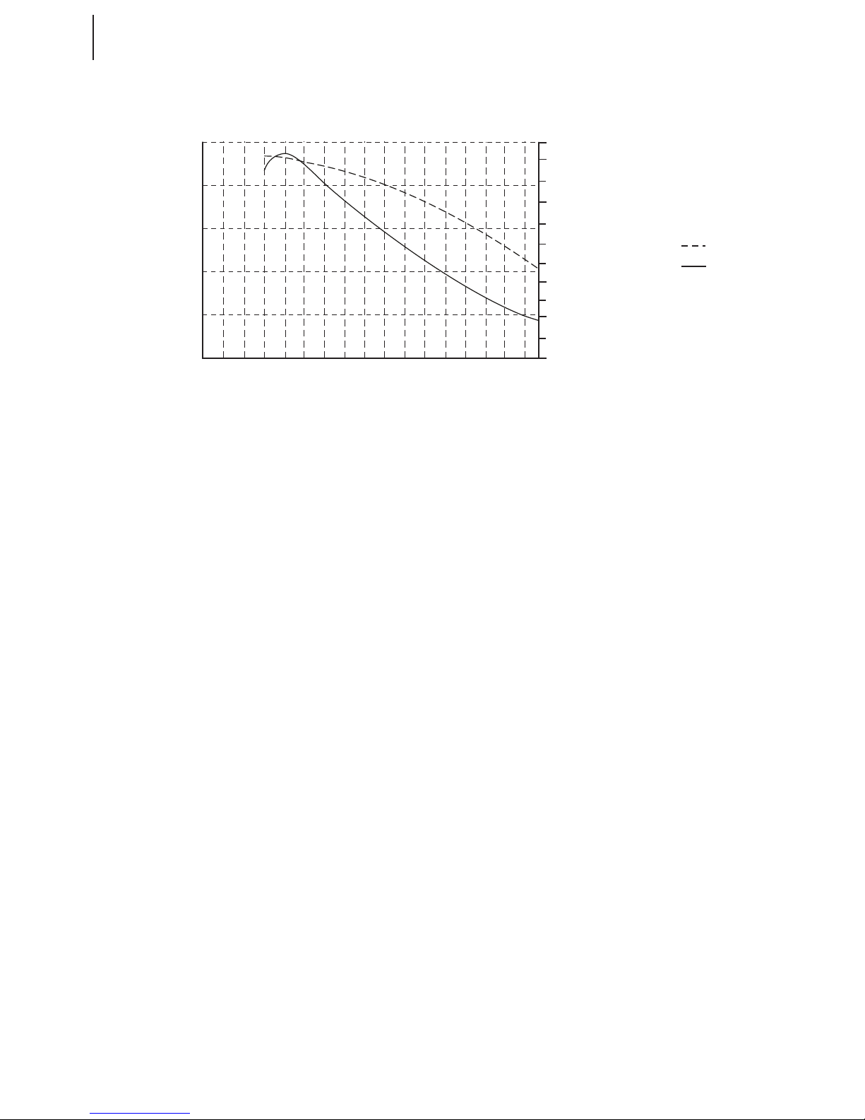
Speed polar (propeller feathered)
10
20
25
15
L/D ratio
EAS (km/h)
60
120 140
160
200
80
180
220
70
110 130
150
190
90
170
210
225
100
30
5
-9 -1800
-5 -1000
-3 -600
-7 -1400
-1 -200
-11 -2200
sink rate
sink rate
L/D ratio
m/s fpm

Sinus 912 LSA Glider 550 MTOW
www.pipistrel.eu
REV. 3
Weight and balance
Introduction (6-2)
Weighing procedure (6-2)
Equipment list (6-3)
Determination of CG (6-3)
Sample CG calculation (6-4)
6 Weight and balance
6-1

Sinus 912 LSA Glider 550 MTOW
www.pipistrel.eu
REV. 3
Introduction
This section describes the procedure for establishing the basic empty weight and moment of the airplane. Sample calculations are provided for reference. For additional information regarding Weight
and Balance procedures, refer to the Aircraft Weight and Balance Handbook (FAA-H-8083-1). Specic
information regarding the weight and arm for this airplane as delivered from the factory can be
found in the aircraft documentation folder, look for Weight and Balance Report.
WARNING! It is the responsibility of the pilot to make sure the airplane is loaded properly.
Operation outside of prescribed weight and balance limitations could result in an accident and
serious or fatal injury.
Weighing procedure
Make sure all listed aircraft parts and appliances are installed and in position.
Remove all other objects (e.g. tools, mops, tie downs and other things ...).
Empty fuel tanks except for the unusable fuel, inate tires to recommended operating pressures.
Fill up engine oil to the top marking.
Retract aps and airbrakes (optional), leave control surfaces centred.
Level the aircraft inside a closed space - use the provided airfoil template at lower side of the wing
close to the wing root and make sure its straight edge is level (horizontal).
Once leveled, read the scale readings and subtract eventual tare weight.
Now record all readings and ll out the bottom table.
Datum is wing’s leading edge at wing root. Calculate the lever arm of CG using this formula:
Lever arm of CG (X) = ((G1 / G) x c) - a
Weighing form
Weighing point and symbol Scale reading Tare Nett
right main wheel (GD)
left main wheel (GL)
nose wheel (G2)
total (G = GD + GL +G2)
Weight and balance
6-2

Sinus 912 LSA Glider 550 MTOW
www.pipistrel.eu
REV. 3
Equipment list
Aircraft’s empty weight data is unique for each and every Sinus 912 LSA delivered. The owner is responsible for keeping the equipment list up to date
Sinus 912 LSA model:
Serial number:
Registration number:
Installed equipment:
Determination of CG
Weight (lbs)
Weight’s lever
arm (inch)
Moment
(in x lb)
Remarks
Basic cfg. empty weight
Baggage 46
Instruments - 12.5 minus!!!
Pilots 10.2
Fuel 4
CAUTION! Each newly installed part or appliance must be registered in the upper table. Also,
new total weight and lever arm of CG values must be entered and position of CG re-determined.
Furthermore, the moment must be recalculated. This is rather unchallenging to do. First multiply
the new part’s weight by it’s lever arm measured from the reference point (wing’s leading edge).
Then sum up all momentums and divide the sum by the new total weight.
WARNING! Aircraft's safe center of gravity position ranges between 9.5'' and 16.0'' aft of da-
tum and is not critically aected by cockpit crew weight or weight of fuel on board in any way.
WARNING! Absolute safe measure for the amount of luggage is 55 lbs. The actual amount
of luggage you can safely transport depends on the centre of gravity of empty aircraft. See next
pages.
Weight and balance
6-3

Sinus 912 LSA Glider 550 MTOW
www.pipistrel.eu
REV. 3
Sample c.g. calculation
Guidelines
Gtotal is the total mass of empty aircraft. All calculations can be performed with aircraft empty
weight and empty weight centre of gravity (c.g.), as the pilots sits directly below the centre of gravity
and do not cause the c.g. to shift. The amount of fuel quantity also has no impact on the c.g..
WARNING! Both pilots’ weight and weight of fuel do not inuence c.g. or their inuence is
insignicant. However, baggage can inuence the c.g. severely and may cause the aircraft to
become uncontrollable!
Basic CG formulas and calculation
The below instructions are valid for Sinus 912 LSA Tail Wheel and Nose Wheel editions. Read thoroughly. Note also that the basic c.g. at 287 mm will be used purely as an example.
First, weigh the aircraft according to the procedure described in this chapter and write down values
of G1 (sum of scale readings at main wheels) and G2 (scale reading at tail/front wheel). Then calculate the position of c.g. in millimeters (mm) from the datum (wing’s leading edge at wing root).
For Tail wheel edition of Sinus use the following formula:
where:
G2tail is the scale reading at the tail wheel,
Gtotal is the sum of G1 and G2tail (G1+G2tail), a.k.a. aircraft empty weight
a is the distance from main wheel axis to wing’s leading edge,
b is the distance between main and tail wheel axis.
For Nose wheel edition of Sinus use the following formula:
where:
G2back is the sum of scale readings at both main (back) wheels,
Gtotal is the sum of G1 and G2back (G1+G2back), a.k.a. aircraft empty weight
a is the distance from nose wheel axis to wing’s leading edge,
b is the distance from main wheel axis to wing’s leading edge,
c = (a+b) is the sum of both distances above.
Second, determine the c.g. position in percentage (%) of Mean Aerodynamic Chord (MAC) with following the formula:
where:
CGmm is the position of CG in millimeters (mm),
R is the dierence between wing’s leading edge and MAC’s leading edge (69 mm),
MAC is the Mean Aerodynamic Chord (869 mm).
Weight and balance
6-4
CG
mm
G
total
+=a + 110 = 287mm mm
=
G2 x b G2 x 4300 mm
tail tail
G
total
CG
mm
G
total
-=a - 1020 = 287mm mm
=
G1 x c G1 x 1525 mm
back back
G
total
CG
%MAC
x 100 =
x 100 = 25.1%
=
CG - R 287mm - 69mm
mm
MAC 869mm

Sinus 912 LSA Glider 550 MTOW
www.pipistrel.eu
REV. 3
Baggage and CG
The amount of baggage you can carry in the solid baggage compartment or in the baggage pouch
behind the seats is limited by the centre of gravity of the empty aircraft (pilots’ and fuel weight do
not inuence c.g.) and the MTOM.
To calculate how much the c.g. shifts because of added baggage into the solid baggage compartment or the baggage pouch behind the seats use the following formula:
where:
Gtotal is the aircraft empty weight,
CGmm is the position of CG of empty aircraft in millimeters (mm),
Gbags is the weight of the baggage,
Lbags is the lever arm from the datum to baggage area (1160 mm).
Again, express the new c.g. in percentage of MAC:
where:
CGwith.bags is the position of CG now with bags in millimeters (mm),
R is the dierence between wing’s leading edge and MAC’s leading edge (69 mm),
MAC is the Mean Aerodynamic Chord (869 mm).
We now have the data of c.g. of the sample aircraft with 22 lbs (10 kgs) of baggage. You can recalculate the formulas using the weights and c.g. of your empty aircraft and the planned amount of baggage for your ight.
CAUTION: The baggage weight limitations in this manual represent fool-proof limits for safe
operation, even without special c.g. calculation. However, the actual baggage weight limitation
is dierent of each individual aircraft and can be determined using the above formulas. The decision of how much baggage to carry on a ight is at pure responsibility of the pilot in command!
WARNING! Always make sure that the baggage is placed xed inside the baggage area.
Movements of baggage in-ight will cause shifts of centre of gravity!
WARNING! Do not, under any circumstances attempt to y the aircraft outside the allow-
able c.g. limits! Allowable c.g. range is between 9.5’' and 16.0'', measured from the wing's leading
edge backwards which corresponds to 20% - 39% MAC)
WARNING! Maximum takeo weight (MTOM) MUST NOT, under any circumstances, exceed
1210 lbs (550 kg).
Weight and balance
6-5
()() () +
()
GxCG +G x L 292kg x 287mm 10kg x 1160mm
totalmm bags mm
=316mm
292 + 10kg kg
CG =
with bags
=
G+ G
total bags
CG =
(+bags)%MAC
CG - R 316mm - 69mm
with bags
x 100 = 28.4%
x 100 =
MAC 869mm

Sinus 912 LSA Glider 550 MTOW
www.pipistrel.eu
REV. 3
This page is intentionally left blank.
6-6

Sinus 912 LSA Glider 550 MTOW
www.pipistrel.eu
REV. 3
Introduction (7-2)
Cockpit controls (7-4)
Instrument panel (7-4)
Undercarriage (7-6)
Seats and safety
harnesses (7-6)
Pitot-static system (7-6)
Air brakes (7-6)
Power plant (7-7)
Fuel system (7-8)
Electrical system (7-9)
Engine cooling system (7-13)
Engine lubrication system (7-14)
Wheel brake system (7-14)
7 Description of Aircraft & Systems
7-1
Description of Aircraft & Systems
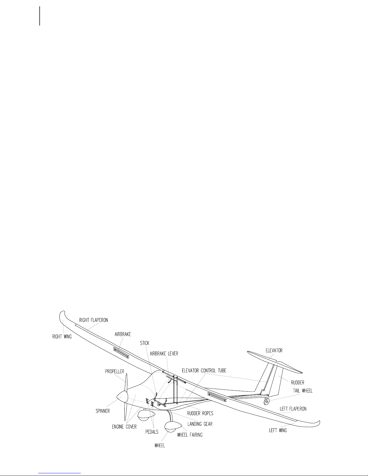
Sinus 912 LSA Glider 550 MTOW
www.pipistrel.eu
REV. 3
Sinus 912 LSA is a 49 ft (14.97 m) wingspan,
two-seat T-tail motorglider made almost entirely of composite materials. Its low-drag,
high-wing-monoplane, engine-at-the-front
construction makes it ecient even when ying unpowered. In fact, the propeller can be
feathered to reduce drag even more.
The undercarriage is a tricycle type with two
main, brake equipped, wheels mounted on
struts and a steerable nose wheel.
Sinus 912 LSA features aperons, interconnected aps and ailerons presented in the same
deecting surface. Flaps oer 4 settings: neutral, 1st, 2nd and the negative (reex) position
Full dual main ight control levers make Sinus
912 LSA ideal for initial as well as for advanced
ight training. All aileron, elevator and ap
controls are connected to the cabin controls
using self-tting push-pull tubes. Rudder is
controlled via cables. The elevator trim is mechanical, spring type.
Airbrakes are available as standard, they reduce the requirements for runways size for
landing and provide for steeper approaches
and expedite descents.
All aircraft ship with H type safety belt attached to the fuselage at three mounting
points. Rudder and brake pedals can be adjusted also during ight to suit your size and
needs.
Fuel tanks are located inside the wings. Fuel
selector is in the form of two separate valves,
located on the left and right upper wall of the
cabin. The gascolator is located beneath the
lower engine cover.
Refuelling can be done by pouring fuel
through the fuel tank openings on top of the
wings or by using an electrical fuel pump.
All glass surfaces are made of 2 mm anti UV GE
tinted Lexan, which was specially developed
not to shatter or split on impact.
Main wheel brakes are hydraulically driven disc
type. The hydraulic brake uid used is DOT 3 or
DOT 4.
Cabin ventilation is achieved through special
vents tted onto glass doors, cabin heating,
however, is provided utilizing hot air from the
engine.
To enhance aerodynamics even more, every
Sinus 912 LSA comes equipped with special
wheel fairings and the propeller spinner. The
propeller is a ground adjustable composite
two blade design.
The electric circuit enables the pilot to test
individual circuit items and to disconnect the
entire wiring but leave the engine running,
should there come to a distress situation.
Navigational (NAV), anti collision (AC) and
landing (LDG) lights are an option.
The rewall is reinforced by heat and noise insulation.
Basic instruments come installed with operational limits pre-designated, advanced avionics
in form of EFIS glass cockpits etc. are an option.
Parachute rescue system is an option.
Optional is the also the side access door to the
cargo compartment behind the seats.
Introduction
Description of Aircraft & Systems
7-2

Sinus 912 LSA Glider 550 MTOW
www.pipistrel.eu
REV. 3
Composite parts are made of:
fabric: GG160, GG200, 90070, 92110, 92120, 91125, 92140, 92145, KHW200
roving: NF24
foam: 75 kg/m3 PVC 3mm, PVC 5 mm, PVC 8mm
GFK: 3 mm, 5 mm, 7 mm of thickness
paint: acrylic paint
rewall glass-aluminium sandwich
Medal parts used are:
tubes: materials: Fe0146, Fe 0147, Fe0545, Fe1430, AC 100, CR41 in LN9369
sheet metal: materials: Fe0147 in Al 3571
rods: materials: Fe 1221, Fe 4732, Č4130, Al 6082, CR41 in Al 6362
cable: AISI 316
bolts and nuts: 8/8 steel
All composite parts are made of glass, carbon and kevlar ber manufactured by Interglas GmbH.
All parts have been tested at safety factor of a minimum 1.875.
All composite parts are made in moulds, therefore no shape or structural dierences
can occur.
All parts and materials used in Sinus 912 LSA are also being used in the glider and
general aviation industry and all comply with aviation standards.
Description of Aircraft & Systems
7-3

Sinus 912 LSA Glider 550 MTOW
www.pipistrel.eu
REV. 3
Cockpit levers
Sinus 912 LSA’s cockpit levers are divided into two groups:
Individual control levers: pilot stick and rudder with dierential brake levers
Joint control levers: throttle lever, chock lever, ap lever, trim lever, airbrakes lever (if applicable),
fuel valves, door handles, battery disconnection lever/ring and emergency parachute release handle.
Instrument panel
Small instrument panel (left) with Brauniger as the middle screen - Large instrument panel with two
screen setup (Dynon D100 and EMS 120). Both are for illustration purpose only!
Description of Aircraft & Systems
7-4

Sinus 912 LSA Glider 550 MTOW
www.pipistrel.eu
REV. 3
There are two types of instrument panels, the big and small version, both equipped with the
Brauniger Alpha MFD as the standard multifunction instrument. Factory approved options are a
single Dynon D180 EFIS/EMS as the main instrument or dual screen es setup with Dynon D100 and
EMS120. All instruments have ight data recording capabilities and display all necessary ight and
engine data to the pilot. Since 2010 Dynon Skyview SV-700 (single and dual screen) and SV-1000
(single screen) are an option. When a GPS unit is factory tted the GPS data is transmitted to the
glass cockpit instrument via a cable and a NMEA protocol. For additional information consult individual operators manuals for the instruments installed.
Notes on Brauniger Alpha MFD multifunction instrument
• The new version of Brauniger Alpha MFD multifunction instrument (V315) also features an acoustic
vario-meter and an acoustic VNE alarm.
• Certain Brauniger Alpha MFD installations require the multifunction instrument to be
switched ON separately from the aircraft’s master switch.
• Always make sure the instrument is switched OFF when you leave the aircraft so as not to
discharge its internal battery.
The cockpit electrical switch panel has separate magneto- master switch and starter switch.
The toggle switches used in the main sector have integrated automatic thermal circuit breakers.
Description of Aircraft & Systems
7-5

Sinus 912 LSA Glider 550 MTOW
www.pipistrel.eu
REV. 3
Undercarriage
The undercarriage is a tricycle type with two main, brake equipped, wheels mounted on struts and a
steerable nose wheel. The nose wheel steers through rudder pedals
distance between main wheels: 63 inch (1.6 m)
distance between main and nose wheel: 60 inch (1.52 m)
tire: 4,00'' x 6'' (main wh.), 4,00'' x 4'' (nose wh.)
tire pressure 24 psi - 28 psi (main wh.), 18 psi (nose wh.)
brakes: disk type, driven by brake pedals located on both rudder pedals
brake uid: DOT 3 or DOT 4
Beringer high performance brakes with the parking brake is optional equipment. To apply the parking brake, depress the pedal brake levers, hold them engaged and pull the parking brake lever (on
the side of the instrument column in front of the control stick). Then release the pedal brake levers.
To disengage, push the parking brake levers to full forward position.
Seats and safety harnesses
Seats have no sti internal structure and can therefore be folded easily for luggage access. The seat
has one position, whereas the pedals are adjustable. Custom made seats are available for ordering.
All Sinus 912 LSA ship with H type safety harness attached to the fuselage at three mounting points.
Pitot-Static tubes
The pitot tube is attached to the bottom side of the right-hand wing. Pitot lines made of plastic
materials lead through the inside of the wing all the way to the instrument panel. Pitot heat and an
AOA-indication pitot are optional
Air brakes
Air brakes are most commonly used to increase drag and steepen the nal approach. They are standard equipment on the Sinus 912 LSA. Airbrakes make the total landing distance equivalent to the
total take-o distance, enabling you to use STOL runways for your operations.
During takeo, climb and cruise air brakes MUST be retracted and locked (handle in cockpit in full up
position). To unlock and extend air brakes, press on the release lever and pull the handle downwards
Description of Aircraft & Systems
7-6

Sinus 912 LSA Glider 550 MTOW
www.pipistrel.eu
REV. 3
Power plant
Sinus 912 LSA is equipped with Rotax 912 UL 80 HP engine
Engine description:
Engine: ROTAX 912 UL 80 HP (4-stroke boxer, four cylinders, 1211 cm3)
twin carburated - dual electronic ignition
cooling: crank case aircooled, cylinder heads watercooled - own radiator and
pump, other moving parts oilcooled - own radiator and pump
lubrication: centrally oiled - own oil pump and radiator
reduction gearbox: integrated
reduction ratio: 1 : 2.27
el. generator output power: 250 W at 5500 RPM
starter: electric
engine power: 80 HP at 5800 RPM
battery: 12 V, 10 Ah
All metal cables used are re resistant, kept inside metal, self-lubricating exible tubes.
Schematic of throttle and choke control
Throttle
Choke
Choke
Throttle
Throttle
Choke
2130mm/2280mm
1600mm/1670mm
1200mm/970mm
1200mm/1400mm
410mm/620mm
420/800mm
Description of Aircraft & Systems
7-7
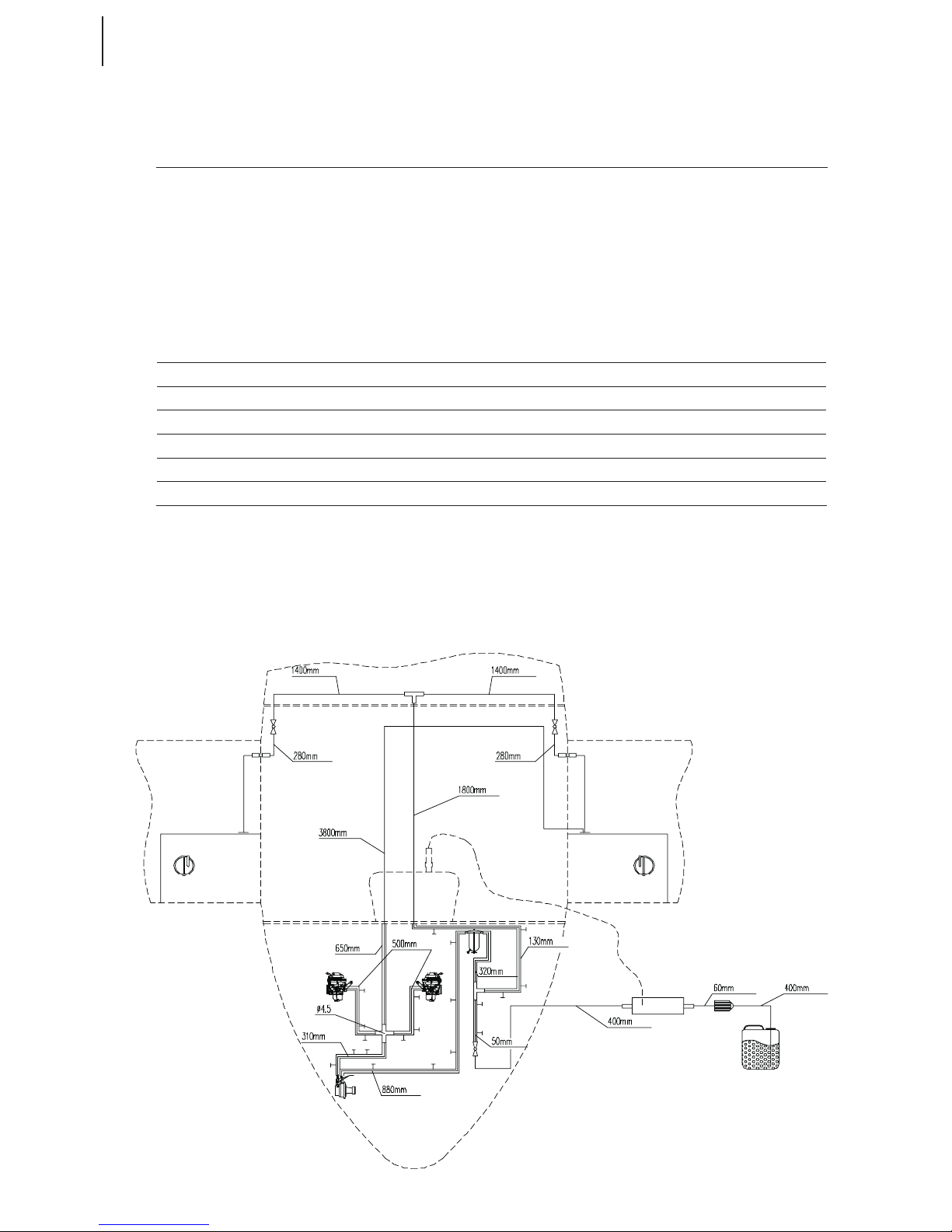
Sinus 912 LSA Glider 550 MTOW
www.pipistrel.eu
REV. 3
Propeller types:
propeller Pipistrel
F2-80 (for Rotax 912 UL 80 HP):
twin blade, ground adjustable or Vario composite propeller
- diameter 63’’ / 1620 mm
Depending on the conguration, the propeller may be ground adjustable or featherable. In the latter case the propeller can be feathered when the engine is not running. No specic limitations apply,
apart from checking the propeller pitch travel during the preight inspection. Do not attempt to restart the engine in ight above 50 kts.
Fuel system
description: vented wing fuel tanks with refuelling cap on top of the wings
fuel selector valves: separated, one for each fuel tank
gascolator: lter equipped with drain valve
fuel capacity std. tanks: 7.25 + 7.25 US gal (30+30 L)
fuel capacity lng. range: 13 + 13 US gal (50 + 50 L)
unusable fuel (per reservoir): 0.75 US gal (3 L)
fuel lter: inside the gascolator
All fuel hoses are protected with certied glass-teon covers. Sinus 912 LSA’s fuel system features
fuel return circuit. The fuel connectors from fuselage to the wing tanks can be either xed or click-on
fast type.
Schematic of fuel system (fuel return circuit)
Description of Aircraft & Systems
7-8

Sinus 912 LSA Glider 550 MTOW
www.pipistrel.eu
REV. 3
WARNING! Visual fuel quantity indicator (tubes) in cockpit do not always provide relevant
information about the actual fuel quantity on board. Because of wing dihedral, angle of attack,
sideslip and reservoir supply point the readout may be incorrect. Flying with less than 1.5 Inch
(30 mm) (see red marking!) of indicated fuel (measured from the bottom of the tube upwards in
any of the reservoirs) is therefore regarded as hazardous any may result in engine fuel starvation
and/or engine failure.
CAUTION! Due to the position of the fuel reservoir supply point, ying in considerable sideslip
for a long time may result in fuel starvation to the engine if the fuel tank in the opposite direction of the sideslip is closed. Should this occur, righten the ight and re-open the fuel tank in
question immediately to prevent engine failure.
Draining of water and/or particles is carried out by draining the contents of the gascolator, installed
below the bottom engine cover and reachable through a dedicated placarded opening. Unscrew the
discharge valve and drain at least 1 cup of fuel in a transparent canister, verify for water/particle contamination. Always fasten the draining valve before ight!
When using the single point fuel valve, found below the cowl opening (placarded), make sure you
have closed it before ight. The single point fuel valve can either be used for fuelling the aircraft by
using a pump and container, or for discharging all of the fuel on board before disassembling the
aeroplane.
Electrical system
description: Dual electronic ignition. Standard, 12 V circuit charges the battery and
provides power to all appliances and instruments.
master switch: key type
avionics switch: avionics active with key position II
ignition switches: separated for each system
other switches: fused and equipped with control lights
battery: 12 V, 10 Ah
measured power
consumption of some
circuit breakers:
Landing light: 4.5 A,
Nav/Strobe lights: 1 (steady) - 2 (peak) A , Cockpit light: 0.5 A,
Radio & Transponder, EFIS, autopilots:
Please consult item’s operating manual
Characteristic are separate magneto switches in form two toggle switches and a key-type three
stage master switch, which also operated as the avionics switch. Therewith are individual fused rocker switches used to control individual electrical loads (radio, transponder, lights, es, ems, autopilot,
etc.).
The only electrical load which can be used without the master switch in either ALL ON or ENGINE
only position is the 12 V plug, all other loads function only when the master (key) is in the ALL ON
position.
The position I (ENGINE ONLY) is there to provide continuous operation of the engine in case of emergency, where all other electrical load (12 V plug is the exception) are disengaged.
Description of Aircraft & Systems
7-9

Sinus 912 LSA Glider 550 MTOW
www.pipistrel.eu
REV. 3
Schematic of electrical system (before late-2010)
Description of Aircraft & Systems
7-10

Sinus 912 LSA Glider 550 MTOW
www.pipistrel.eu
REV. 3
Description of Aircraft & Systems
7-11
Pitot heat
Pitot heat is available in combination with the AOA sensing pitot tube. It is the single most powerful
electrical load in the system, consuming more than 100 Watts of power. When activating the pitot
heat (toggle switch on the main electrical panel), monitor system voltage (and or current) to make
sure the battery is not being discharged due to prolonged use of large electrical loads in combination with the pitot heat, both on ground and in ight.
Battery disconnection system
On the Sinus 912 LSA, the main battery can be disconnected from the circuit.
There are two handles in the cockpit used to operate the battery disconnection, the battery disconnection lever and the battery disconnection ring. The battery disconnection lever, which is a red agtype lever is found on the rewall above the main battery on the left-hand side of the cockpit. This
lever has an attached wire which leads to the battery disconnection ring on the instrument panel’s
switch column.
To disconnect the battery from the circuit, simply pull the battery disconnection ring on the instrument panel’s switch column.
To reconnect the battery back to the circuit, use the ag-type lever on the rewall.
Deect the lever so that its ag end points towards the rewall. Having done this correctly, you will
feel the ag-lever lock into position.
Battery reconnection can be done in-ight as well (e.g. following a successfully rectied emergency
situation) but only from the left-hand seat, since you cannot reach the ag-lever from the right-hand
side of the cockpit.
Schematic of electrical system (continued)

Sinus 912 LSA Glider 550 MTOW
www.pipistrel.eu
REV. 3
Engine cooling system
Rotax 912 UL cooling system
The Rotax 912 engine’s cylinders are aircooled, the cylinder heads watercooled. The cooling-air intake is located on the right-hand bottom part of the engine cover.
Cylinder heads are watercooled. The water pump forces water through the radiator, placed behind
the air intake opening on the top engine cover. The engine does not feature a thermostat valve. The
system is pressurised with a pressurised valve placed on one of the hoses. The overow tank uid
level must always be inside the designated limits!
The engine does not feature a cooling fan, therefore cooling is entirely dependant on moving air currents and airspeed.
CAUTION! You are strongly discouraged from leaving the engine running at idle power when
on ground.
The manufacturer recommends use of cooling uids used in car industry diluted in such a manner
that it withstands temperatures as low as - 20°C/-4°F.
Schematic of engine cooling system
Description of Aircraft & Systems
7-12

Sinus 912 LSA Glider 550 MTOW
www.pipistrel.eu
REV. 3
Description of Aircraft & Systems
7-13
Engine lubrication system
Rotax 912 is a four-stroke engine, equipped with a dry sump and lubricated centrally with use of its
own oil pump. All the oil needed is located inside an outer canister. When the engine is running, the
oil cools itself passing through a radiator, located on the left-hand side of the bottom engine cover.
Oil quantity can be checked visually with a oil level bar. Make sure the oil quantity is sucient limits
at all times.
CAUTION! Oil temperature, pressure and quality is strictly dened an must not, under any cir-
cumstances, vary from its safe values.
Schematic of engine lubrication system
Wheel brake system
Wheel brake system features separate braking action for each of the main landing gear. Wheel
brakes are drum or disc, wire driven (old type) or hydraulic type (new type).
Wheel brake levers are operated by pressing the levers mounted on top of the rudder pedals.
Hydraulic brake uid used for hydraulic type brakes is DOT 3 or DOT 4.
Aircraft equipped with the Beringer high-performance brakes feature also a parking brake.

Sinus 912 LSA Glider 550 MTOW
www.pipistrel.eu
REV. 3
Description of Aircraft & Systems
7-14
This page is intentionally left blank.

Sinus 912 LSA Glider 550 MTOW
www.pipistrel.eu
REV. 3
Special inspections (8-2)
Draining & refuelling (8-2)
Connecting Auxiliary
power supplies (8-3)
Tie down (8-4)
Storage (8-4)
Cleaning (8-4)
Keeping your aircraft in
perfect shape (8-5)
8 Handling and servicing
Handling and servicing
8-1

Sinus 912 LSA Glider 550 MTOW
www.pipistrel.eu
REV. 3
Handling and servicing
Special inspections
After having exceeded VNE or landed in a rough manner:
Check the undercarriage, fuselage & wing surfaces and main spars for abnormalities. It is highly
recommended to have the aircraft veried for airworthiness by authorised service personnel.
Clicking noise overhead
The wings are factory tted to the fuselage to make a tight t at approximately 70° F. When exposed
to low temperatures, materials shrink. Therefore, ying in the winter or in cold temperatures, you
may encounter “click-clack” like noises above your head. The remedy for this unpleasant noises is to
add washers, typically of 0,5 mm thickness in-between wing and fuselage. Washers must be added
both at rear and front bushings at one side of the fuselage only!
WARNING! It is mandatory to consult the manufacturer or authorised service personnel
before applying washers!
Draining and refuelling
Whenever draining or refuelling make sure master switch is set to OFF (key in full left position).
Draining the fuel system
The gascolator is located beneath the bottom engine cover on the left hand side of the fuselage.
To drain the fuel system, open the drain valve on the gascolator. Drain approximately 1/2 cup of fuel.
Try to prevent ground pollution by collecting the fuel with a canister.
To close the valve simply turn it in the opposite direction. Do not use force or special tools!
CAUTION! Always drain the fuel system before you have moved the aircraft from a standstill to
prevent mixing of the fuel and eventual water or particles.
Refuelling
CAUTION! Before refuelling it is necessary to ground the aircraft!
Refuelling can be done by pouring fuel through the fuel tank openings on top of the wings or by using the single point fueling valve on the lower rewall.
Refuelling using the electrical fuel pump:
Firstly make sure the fuel hoses are connected to wing connectors and that both fuel valves are
open.
Connect one end of the fuel pump to the valve beneath the bottom engine cowl. Submerge the
other end of the fuel pump, which has a lter attached, into the fuel container.
Engage the fuel pump by engaging the 12 V socket switch on the instrument panel.
After refuelling it is recommended to eliminate eventual air pockets from inside the fuel system. To
do that, drain some fuel with both fuel valves fully open.
Also, leave the engine running at idle power for a couple of minutes prior to taking-o and test the
engine at full power for a minimum of 30 seconds.
8-2

Sinus 912 LSA Glider 550 MTOW
www.pipistrel.eu
REV. 3
Connecting Auxiliary power supplies
Should you be unable to start the engine due to a weak battery, auxiliary power supplies can be connected to help starting the engine.
To connect an auxiliary power supply use battery connector cables with clamps at either ends.
Connect the negative (-) wire to aircraft’s exhaust (sticking out below the engine cowlings).
The positive (+) wire leads inside the cockpit to the relay mounted top-right of the aircraft’s battery
on the rewall. This relay has 3 nipples; the positive (+) wire must be connected to the upper-left
nipple, the only one to which 2 cables are connected to.
After you have connected the wires correctly, start the engine normally by pressing the starter button in the cockpit.
WARNING! The pilot must be in cockpit when starting the engine. The person who will
disconnect the cables after the engine has started must be aware of the danger of spinning
propeller nearby.
Handling and servicing
Battery’s & Relay’s location Battery (black) & Relay (top-right)
Top-left nipple (c. positive (+) wire here) Exhaust (connect negative (-) wire here)
Should you be experiencing slow refuelling with the electrical fuel pump, you should replace the lter. You can use any fuel lter for this application.
It is recommended to use additional plastic tubes attached to the fuel tank vents and leading to the
ground in order to avoid over-spills of fuel onto the airframe when lling the tanks completely
CAUTION! Use authorised plastic containers to transport and store fuel only! Metal canisters
cause for water to condensate on the inside, which may later result in engine failure.
8-3

Sinus 912 LSA Glider 550 MTOW
www.pipistrel.eu
REV. 3
Tie down
Point the aircraft into the wind and retract aps fully. Chock all three wheels. Remove the caps covering mounting holes on the bottom part of the wing (located 15 ft from the fuselage) and carefully
screw in the two screw-in rings provided.
Secure tie-down ropes to the wing tie-down rings at an approximately 45-degree angle to the
ground. When using rope of a non-synthetic material, leave sucient slack to avoid damage to the
aircraft, should the ropes contract. To tie down the tail, tie a rope through the tail skid and secure it
to the ground. At the end, cover the pitot tube with a protection cover.
Mechanical towing is prohibited at all times.
Storage
The aircraft is ideally stored in a hangar. For increased in-hangar maneuverability use of original
push-cart is recommended.
Even for over-night storage it is recommended to leave the airbrakes handle unlocked - hanging
down freely in order to reduce pressure on plate springs and maintain their original stiness.
If a parachute rescue system is installed in your aircraft, make sure the activation handle safety pin is
inserted every time you leave the aircraft.
Apply the tubes onto fuel tank vents so that fuel will not spill onto the wing in event of full fuel
tanks, temperature expansion of fuel and/or parking on a slope.
Also, disconnect the battery from the circuit to prevent battery self-discharge (pull battery disconnection ring on the instrument panel’s switch column) during storage period.
CAUTION! Should the aircraft be stored and/or operated in areas with high atmospheric hu-
midity pay special attention to corrosion of metal parts, especially inside the wings. Under such
circumstances it is necessary to replace the airbrakes connector rod every 2 years.
Cleaning
Use fresh water and a soft piece of cloth to clean the aircraft’s exterior. If you are unable to remove
certain spots, consider using mild detergents. Afterwards, rinse the entire surface thoroughly.
Lexan glass surfaces are protected by an anti-scratch layer on the outside and an anti-fog coating on
the inside of the cabin. Always use fresh water only to clean the glass surfaces, not to damage these
protection layers and coatings.
To protect the aircraft’s surface (excluding glass surfaces) from the environmental contaminants,
use best aordable car wax.
The interior is to be cleaned with a vacuum cleaner.
Handling and servicing
8-4

Sinus 912 LSA Glider 550 MTOW
www.pipistrel.eu
REV. 3
Keeping your aircraft in perfect shape
Precautions
1) Eliminate the use of ALL aggressive cleaning solutions and organic solvents, also the window
cleaning spray, benzene, acetone, aggressive shampoos etc.
2) If you must use an organic solvent (acetone) on small areas remove certain glue leftovers or similar, the surface in question MUST be polished thereafter. The only section where polishing should be
avoided is the edge on the wing where the sealing gasket is applied.
3) When ying in regions with a lot of bugs in the air, you should protect the leading edges of the
airframe before ight (propeller, wings, tail) with Antistatic furniture spray cleaner: “Pronto (transparent), manufacturer: Johnson Wax (or anything equivalent) – Worldwide”, approximate price is only $3
USD / €3 EUR for a 300 ml spray bottle. Using such spray, do not apply it directly onto the wing but
into a soft cloth instead (old T-shirts are best).
4) After having nished with ight activity for the day, clean the leading edges of the airframe as
soon as possible with a lot of water and a drying towel (chamois, articial leather skin). This will be
very easy to do if you applied a coat of Pronto before ight.
Detailed handling (Airframe cleaning instructions)
Every-day care after ight
Bugs, which represent the most of the dirt to be found on the airframe, are to be removed with clean
water and a soft cloth (can be also drying towel, chamois, articial leather skin). To save time, soak all
the leading edges of the airframe st. Make sure to wipe ALL of the aircraft’s surface until it is completely dry.
Clean the propeller and the areas with eventual greasy spots separately using a mild car shampoo
with a wax.
CAUTION! Do not, under any circumstances attempt to use aggressive cleaning solutions, as
you will severely damage the lacquer, which is the only protective layer before the structural
laminate.
When using the aircraft in dicult atmospheric conditions (intense sunshine, dusty winds, coastline,
acid rains etc.) make sure to clean the outer surface more thoroughly.
If you notice you cannot remove the bug-spots from the leading edges of the aircraft, this means the
lacquer is not protected any more, therefore it is necessary to polish these surfaces.
CAUTION! Do not, under any circumstances attempt to remove such bug-spots with abrasive
sponges and/or rough polishing pastes.
Periodical cleaning of all outer surfaces with car shampoo
Clean as you would clean your car starting at the top and working your way downwards using a soft
sponge. Be careful not to use a sponge that was contaminated with particles e.g. mud, ne sand) so
not to grind the surface. While cleaning, soak the surface and the sponge many, many times. Use a
separate sponge to clean the bottom fuselage, as is it usually more greasy than the rest of the airframe. When pouring water over the airframe, be careful not to direct it over the fuel reservoir caps,
wing-fuselage joining section, parachute rescue system straps and cover, pitot tube, tail static probe
and engine covers.
Handling and servicing
8-5

Sinus 912 LSA Glider 550 MTOW
www.pipistrel.eu
REV. 3
Always rinse the shampooed surfaces again before they become dry! Thereafter, wipe the whole of
the aircraft dry using a drying towel, chamois or articial leather skin.
Also, clean the Mylar seals on the wing and tail control surfaces. Lift the seals gently and insert ONE
layer of cloth underneath, then move along the whole span of the seal. Ultimately, you may wish to
apply Teon grease (in spray) over the area where the seal touch the control surfaces.
Polishing by hand
Use only the highest quality polishing compounds WITHOUT abrasive grain, such as Sonax Extreme
or similar. Start polishing on a clean, dry and cool surface, never in the sunshine!
Machine polishing requires more skills and has its own particularities, therefore it is recommended
to leave it to a professional.
Cleaning the Lexan transparent surfaces
It is most important to use really clean water (no cleaning solutions are necessary) and a really clean
drying towel (always use a separate towel ONLY for the glass surfaces). Should the glass surfaces be
dusty, remove the dust rst by pouring water (not spraying!) and gliding your hand over the surface.
Using the drying towel, simply glide it over the surface, then squeeze it and soak it before touching the glass again. If there are bugs on the windshield, soak them with plenty of water rst, so less
wiping is necessary. Ultimately, dry the whole surface and apply JT Plexus Spray ($10 USD / €10 EUR
per spray) or at least Pronto antistatic (transparent) spray and wipe clean with a separate soft cotton
cloth.”
Handling and servicing
8-6

Sinus 912 LSA Glider 550 MTOW
www.pipistrel.eu
REV. 3
Parachute rescue system:
use, Handling and
servicing (9-1)
How fast is too fast (9-4)
Myth: I can fully deect
the controls below
maneuvering speed! (9-7)
Training supplement (9-8)
Conversion tables (9-12)
Preight check-up pictures
(9-18)
9 Appendix
Appendix
9-1

Sinus 912 LSA Glider 550 MTOW
www.pipistrel.eu
REV. 3
Appendix
9-2
Parachute rescue system: use, Handling
and servicing
System description
The GRS rocket charged parachute rescue system provides you with a chance to rescue yourself from
an unexpected situation.
The system is placed inside a durable cylinder mounted on the right hand side of the baggage compartment. Inside this cylinder is the parachute which stored inside a deployment bag with a rocket
engine underneath.
This brand new design deploys a canopy that is not gradually drawn from the container, exposed
to distortion by air currents, but it is safely open after 0,4 to 0,7 seconds in distance of 15-18 metres
above the aircraft. It is carried there in a special deployment bag, which decreases the risk of aircraft
debris fouling the canopy.
The parachute rescue system is activated manually, by pulling the activation handle mounted on the
back wall above. After being red, the man canopy is open and fully inated in about 3.2 seconds.
WARNING! Activation handle safety pin should be inserted when the aircraft is parked or
hangared to prevent accidental deployment. However, the instant pilot boards the aircraft, safety
pin MUST be removed!
Use of parachute rescue system
Typical situations for use of the parachute rescue system are:
•
structural failure
•
mid-air collision
•
loss of control over aircraft
•
engine failure over hostile terrain
•
pilot incapacitation (incl. heart attack, stroke, temp. blindness, disorientation...)
Prior to ring the system, provided time allows:
•
shut down the engine and set master switch to OFF (key in full left position)
•
shut both fuel valves
•
fasten safety harnesses tightly
•
protect your face and body.
To deploy the parachute jerk the activation handle hard to a length of at
least 1 foot towards the instrument panel.
Once you have pulled the handle and the rocked is deployed, it will be about two seconds before
you feel the impact produced by two forces. The rst force is produced by stretching of all the system. The second force follows after the ination of the canopy from opening impact and it will seem
to you that the aircraft is pulled backwards briey. The airspeed is reduced instantly and the aircraft
now starts to descent underneath the canopy.

Sinus 912 LSA Glider 550 MTOW
www.pipistrel.eu
REV. 3
Appendix
9-3
As a pilot you should know that the phase following parachute deployment may be a great unknown and a great adventure for the crew. You will be getting into a situation for the rst time,
where a proper landing and the determination of the landing site are out of your control.
CAUTION! Should you end up in power lines (carrying electrical current), DO NOT under any
circumstances touch any metal parts inside or outside the cockpit. This also applies to anyone
attempting to help or rescue you. Be aware that anyone touching any part of the aircraft while
standing on the ground will probably suer mayor injury or die of electrocution. Therefore, you
are strongly encouraged to conne your movements until qualied rescue personal arrives at the
site to assist you.
After the parachute rescue system has been used or if you suspect any possible damage to the system, do not hesitate and immediately contact the manufacturer!
Handling and servicing
Prior to every ight all visible parts of the system must be checked for proper condition. Special attention should be paid to corrosion on the activation handle inside the cockpit. Also, main fastening
straps on the outside of the fuselage must be undamaged at all times.
Furthermore, neither system, nor any of its parts should be exposed to moisture, vibration and UV
radiation for long periods of time to ensure proper system operation and life.
CAUTION! It is strongly recommenced to thoroughly inspect and grease the activation han-
dle, preferably using silicon spray, every 50 ight hours.
All major repairs and damage repairs MUST be done by the
manufacturer or authorised service personnel.
For all details concerning the GRS rescue system, please see the “GRS - Galaxy Rescue System Manual
for Assembly and Use”.

Sinus 912 LSA Glider 550 MTOW
www.pipistrel.eu
REV. 3
Appendix
How fast is too fast?
Based on two recent unfortunate events, where two pilots lost their newly acquired Sinus and Sinus
aircraft, the team of Pipistrel’s factory pilots decided to stress the importance of airspeed even more.
Do read this passage thoroughly as everything mentioned below aects you as the pilot directly!
The two events
Both the events took place during the rst couple of hours pilots ew with their new aircraft.
Therefore it is denite they had not become completely familiar with all the ight stages Sinus and
Sinus oer. The circumstances of both the events were remarkably similar.
Soon after the pilots picked up their new aircraft at the distributor’s, the aircraft were severely damaged aloft. One during the rst home-bound cross country ight and the other during the rst
ights at domestic aireld. Please note the distributor independently tested both mentioned aircraft
up to VNE at altitudes reaching 300 to 500 metres (900 to 1500 feet) with great success.
Pilots ew their machines at reasonably high altitudes but at very high speeds. One of them deployed airbrakes (spoilers) at the speed of 285 km/h (155 kts) - where the VNE of the aircraft is 225 km/h
(122 kts), the other was ying at 3000 m (10.000 ft) at 270 km/h (145 kts) IAS - where the VNE of the air-
craft was 250 km/h (135 kts).
They both encountered severe vibrations caused by utter. Because of this one aircraft’s fuselage
was shredded and broken in half just behind the cabin (the craw saw saved thanks to the parachute
rescue system), other suered inferior damage as only the aperon control tubes went broken. The
pilot of the second machine then landed safely using elevator and rudder only. Fortunately both pilots survived the accident without being even slightly injured.
Thanks to the Brauniger ALPHA MFD’s integrated Flight Data Recorder, we were able to reconstruct
the ights and reveal what had really happened.
What was the reason for the utter causing both accidents?
Both pilots greatly exceeded speed which should never be exceeded, the VNE.
With the IAS to TAS correction factor taken into consideration, they were both ying
faster than 315 km/h (170 kts)!
You might say: “Why did they not keep their speed within safe limits? How could they be so thoughtless to aord themselves exceeding the VNE?” Speaking with the two pilots they both confessed
they went over the line unawarely. “All just happened so suddenly!” was what they both said.
Therefore it is of vital importance to be familiar to all factors that might inuence your ying to the
point of unawarely exceeding the VNE.
Human factor and performance
The human body is not intended to be travelling at 250 km/h (135 kts), nor is it built to y. Therefore,
in ight, the human body and its signals should not be trusted at all times!
To determine the speed you are travelling at, you usually rely on two senses – the ear and the eye.
The faster the objects around are passing by, the faster you are travelling. True.
The stronger the noise caused by air circulating the airframe, the faster the airspeed. True again.
But let us conne ourselves to both events’ scenarios.
At higher altitudes, human eye loses it’s ability to determine the speed of movement precisely.
9-4

Sinus 912 LSA Glider 550 MTOW
www.pipistrel.eu
REV. 3
Appendix
Because of that pilots, who are ying high up feel like they are ying terribly slow.
At high speeds the air circulating the airframe should cause tremendous noise. Wrong!
In fact the noise is caused by drag. Modern aircraft like Sinus and Sinus, manufactured of composite materials, have so little drag, that they actually sound quieter than you would expect.
Especially if you are used to wearing a headset when ying you must not rely on your ear as the
instrument for determining speed.
REMEMBER! When ying high the only reliable tool to determine airspeed
is the cockpit instrument - the airspeed indicator!
How to read and understand what the airspeed indicator
tells you?
Let us rst familiarise with the terms used below:
IAS: stands for Indicated Air Speed. This is the speed the airspeed indicator reads.
CAS: stands for Calibrated Air Speed. This is IAS corrected by the factor of aircraft’s attitude. No pi-
tot tube (device to measure pressure used to indicate airspeed) is positioned exactly parallel to the
airow, therefore the input speed – IAS – must be corrected to obtain proper airspeed readings. With
Sinus and Sinus, IAS to CAS correction factors range from 1,00 to 1,04.
TAS: stands for True Airspeed. TAS is often regarded as the speed of air to which the aircraft’s air-
frame is exposed. To obtain TAS you must have CAS as the input value and correct it by pressure altitude, temperature and air density variations.
The maximum structural speed is linked to IAS. But light planes, manufactured of carbon reinforced
plastics, with long, slick wings are more prone to utter at high speeds than to structural failure.
So utter is the main factor of determining VNE for us and most other carbon-reinforced-plastic
aircraft producers. Flutter speed is linked to TAS, as it is directly caused by small dierences in
speed of air circulating the airframe. Hence air density is not a factor. For all who still doubt this, here
are two quotes from distinguished sources on utter being related to TAS:
“Suce to say that utter relates to true airspeed (TAS) rather than equivalent airspeed (EAS), so aircraft that are operated at or beyond their VNE at altitude - where
TAS increases for a given EAS – are more susceptible to utter...”
New Zealand CAA’ Vector Magazine (full passage at page 5 of http://www.caa.govt.nz/fulltext/vector/vec01-4.pdf)
“The critical utter speed depends on TAS, air density, and critical mach number. The air
density factor is almost canceled out by the TAS factor; and most of us won’t y fast
enough for mach number to be a factor. So TAS is what a pilot must be aware of!”
Bob Cook, Flight Safety International
The airspeed indicator shows you the IAS, but this is sadly NOT the speed of air to which the
aircraft’s airframe is exposed.
IAS and TAS are almost the same at sea level but can greatly dier as the altitude increases. So
ying at high altitudes, where the air is thinner, results in misinterpreting airspeed which is being indicated. The indicated airspeed value may actually be pretty much lower than speed of air to which
the aircraft is exposed, the TAS.
So is VNE regarded as IAS or TAS? It is in fact regarded as TAS above 4000m/13100 ft!!! You
should be aware of that so that you will not exceed VNE like the two pilots mentioned have.
9-5

Sinus 912 LSA Glider 550 MTOW
www.pipistrel.eu
REV. 3
Appendix
How much dierence is there between IAS and TAS
in practical terms?
Data is for standard atmosphere. To obtain correct speeds for particular atomospherical conditions
please take advantage of the table on page 85 of this manual.
The table below indicates how fast you may y at a certain altitude to maintain
constant True Air Speed (TAS).
TAS [km/h (kts)] IAS [km/h (kts)] TAS [km/h (kts)] IAS [km/h (kts)]
1000 m 3300 ft 250 (135) 237 (128) 270 (145) 256 (138)
2000 m 6500 ft 250 (135) 226 (122) 270 (145) 246 (133)
3000 m 10000 ft 250 (135) 217 (117) 270 (145) 235 (126)
4000 m 13000 ft 250 (135) 206 (111) 270 (145) 226 (121)
5000 m 16500 ft 250 (135) 195 (105) 270 (145) 217 (117)
6000 m 19700 ft 250 (135) 187 (101) 270 (145) 205 (110)
7000 m 23000 ft 250 (135) 178 (96) 270 (145) 196 (103)
8000 m 26300 ft 250 (135) 169 (91) 270 (145) 185 (98)
The table below indicates how TAS increases with altitude while keeping IAS constant.
IAS [km/h (kts)] TAS [km/h (kts)] IAS [km/h (kts)] TAS [km/h (kts)]
1000 m 3300 ft 250 (135) 266 (144) 270 (145) 289 (156)
2000 m 6500 ft 250 (135) 279 (151) 270 (145) 303 (164)
3000 m 10000 ft 250 (135) 290 (157) 270 (145) 316 (171)
4000 m 13000 ft 250 (135) 303 (164) 270 (145) 329 (178)
5000 m 16500 ft 250 (135) 317 (171) 270 (145) 345 (186)
6000 m 19700 ft 250 (135) 332 (179) 270 (145) 361 (195)
7000 m 23000 ft 250 (135) 349 (188) 270 (145) 379 (204)
8000 m 26300 ft 250 (135) 366 (198) 270 (145) 404 (218)
As you can see from the table above the dierences between IAS and TAS are not so little and
MUST be respected at all times!
REMEMBER!
• Do not trust your ears.
• Do not trust your eyes.
• Trust the instruments and be aware of the IAS to TAS relation!
Always respect the limitations prescribed in this manual!
Never exceed the VNE as this has proved to be fatal!
Keep that in mind every time you go ying. Pipistrel wishes you happy landings!
9-6

Sinus 912 LSA Glider 550 MTOW
www.pipistrel.eu
REV. 3
AppendixAppendix
Myth: I can fully deect the controls below
maneuvering speed!
WRONG! BELIEVE THIS AND DIE!
The wing structure in light planes is usually certied to take +3.8 G’s, -1.52 G’s (plus a certain safety
factor). Put more load on the wing than that and you should consider yourself dead.
But here is the nice part: Below a certain speed, the wing simply cannot put out a full 3.8 G’s of lift! It
will stall rst! This speed is called Maneuvering Speed or Va.
Maneuvering Speed is dened as the maximum speed the plane can be ying at and still stall
before the wing breaks no matter how much you pull back on the stick. If you are going slower
than the Va and you pull the stick all the way back, the wing will stall without braking physically.
If you are going faster than the Va and you pull the stick all the way back, the wing can put out so
much lift that it can be expected to break. Therefore people think they can deect the stick as much
as they desire below Maneuvering Speed and stay alive.
Wrong! The Maneuvering Speed is based on pulling back on the stick, not pushing it forward!
Note what was said above: The Va is dened as how fast you can y and not be able to put out more
than 3.8 G’s of lift. But while the plane is certied for positive 3.8 G’s, it is only certied for a nega-
tive G-load of 1.52 G’s! In other words, you can fail the wing in the negative direction by pushing
forward on the stick well below the Va! Few pilots know this.
Also, for airliners, certication basis require that the rudder can be fully deected below
Maneuvering Speed, but only if the plane is not in a sideslip of any kind! (e.g. crab method of approach) Does this make sense at all? Why would you need to fully deect the rudder if not to
re-establish wings-level ight?
In a wonderfully-timed accident shortly after Sept. 11th, 2001 of which everybody thought might be
an act of terrorism, an Airbus pilot stomped the rudder in wake turbulence while the plane was in
a considerable sideslip. The combined loads of the sideslip and the deected rudder took the
vertical stabilizer to it’s critical load. A very simple numerical analysis based on the black box conrmed this. The airplane lost it’s vertical stabilizer in ight and you know the rest.
Also, if you are at your maximum allowable g-limit (e.g. 3.8) and you deect the ailerons even
slightly, you are actually asking for more lift from one wing than the allowable limit!
Therefore combined elevator and aileron deections can break the plane, even if the elevator
is positive only!
SO, WHEN YOU THINK THAT YOU CAN DO AS YOU PLEASE WITH THE CONTROLS BELOW
MANEUVERING SPEED, YOU ARE WRONG!
Please reconsider this myth and also look at the Vg diagram and the aircraft’s limitations to prove it
to yourself.
9-7

Sinus 912 LSA Glider 550 MTOW
www.pipistrel.eu
REV. 3
Training/Familiarization Supplement
This chapter has been written to assist owners/pilots/instructors of Sinus 912 LSA on their quest to learn
how to safely and eciently y this aircraft in addition to the information already assembled in the rest
of this POH. This section will cover most operations the aircraft oers in an order established in section
Normal procedures and recommended speeds. Please consider what follows as an add-on to that chapter.
Engine start-up
First and foremost make sure you have sucient fuel quantity on board for the desired length of
ight. If you are not completely condent there is enough, step out of the aircraft and add more fuel
into the tanks. There is an old aviators’ saying: “The only time you have too much fuel is when you are on
re.”
When engaging the engine starter, wheel brakes MUST be engaged. To keep your propeller in
perfect condition, avoid starting up on areas where there are small stones on the ground. Those little
stones can easily be picked up by the propellers causing damage to the blades.
Warming up must be conducted below 2500 RPM. When reaching safe operational engine temperatures, verify maximum engine ground RPM. Hold the stick back completely and slowly(!) add
throttle to full power, then verify RPM.
Taxi
Taxiing with the Sinus 912 LSA is rather simple considering the steerable nose wheel. For sharper
turns on the ground you can also use wheel brakes to assist yourself. It is recommended you taxi
slow, up to 10 km/s (5 kts), while holding the stick back fully to ease the pressure of the nose wheel.
During taxiing monitor engine temperatures. Due to low airow around the radiators the CHT and
Oil temperature will rise during long taxi periods. If you are holding position, do not leave throttle at
idle. It is better you have some 2500 RPM as this will provide some airow from the propeller to the
radiators and the temperatures will not rise so quickly. Should you see engine temperatures exceed
safe operational values, shut o the engine, point the aircraft’s nose into the wind and wait for
the temperatures to reduce.
Take o and initial climb
Having checked and set all engine and aircraft parameters, you should be ready for take o by now.
Reverify both fuel valves be open and the airbrakes retracted and locked (handle full up). Trim
lever should be in the middle.
Start the take-o roll gradually. Keep adding throttle slowly and smoothly full power. There are two
reasons for this. First, you change ight stage from zero movement to acceleration slowly; this provides you with time to react to conditions. Second, especially if taking-o from a gravel runway, this
method of adding full throttle will prevent the little stones on the runway from damaging the propeller. Extremely short runways are an exception. There you should line up the aircraft, set aps to 2nd
stage, step on the brakes, apply full power and release the brakes.
As you start to move, pull the stick 1/3 of elevator’s deection backwards to ease the pressure on
the nose wheel and lift it o the runway slightly. Do not use full back deection as this will cause
the aircraft’s tail to touch the ground.
Appendix
9-8

Sinus 912 LSA Glider 550 MTOW
www.pipistrel.eu
REV. 3
Appendix
When the nose wheel has lifted o the ground, there is nothing else but to hold the same pitch
attitude and the aircraft will become airborne. Crosswind take-os, depending on wind strength,
require a little bit of aileron deection into the wind. Remember, wings must stay level throughout
ground-roll, rotation and initial climb!
Having lifted o the ground, gently push the stick forward just a bit to accelerate. At some 90
km/h (50 kts) set aps to 1st stage, at 110 km/h (60 kts) set them to neutral.
Climb
A comfortable setting for climb is aps in neutral position, speed of 70 kts (130 km/h) at or slightly
below 5500 RPM. In summer time or when outside temperature exceeds 30°C you should consider
climbing at some 85 kts (160 km/h) to provide more airow to the engine radiators. Trim the aircraft
for comfortable stick forces.
Cruise
Passing through 85 kts (160 km/h), set aps to negative position (handle full down). A comfort-
able cruise setting is 5300 engine RPM. As the Sinus is sensitive to ap settings, especially when it
comes to fuel eciency, ALWAYS use negative stage of aps beyond 85 kts (160 km/h) and neutral
for level ight below 70 kts (130 km/h).
Cruising fast, do not kick-in rudder for turns! Above 85 kts (160 km/h) the rudder becomes almost
insignicant in comparison to aileron deections when it comes to making a turn. Cruising fast, it
is extremely important to y coordinated (ball in the middle) as this increases eciency and decreases side-pressure onto vertical tail surfaces. Also, pay attention to turbulence. If you hit turbulence at speeds greater than VRA, reduce power immediately and pull the nose up to reduce
speed.
If ying a trac pattern, keep aps in neutral position and set engine power so that airspeed does
not exceed 150 km/h (80 kts).
Descent
Descending with the Sinus is the stage of ight where the most care should be taken. As the aircraft
is essentially a glider, it is very slippery and builds up speed very fast.
Start the descent by reducing throttle and keep your speed below VRA.
During initial descent it is recommended you trim for a 10 kts lower speed than the one you decided
to descent at. Do this for safety. In case you hit turbulence simply release forward pressure on the
stick and the aircraft will slow down.
Also, keep in mind you need to begin your descent quite some time before destination. A comfortable rate of descent is 500 fpm (2.5 m/s). So it takes you some 2 minutes for a 1000 ft (300 m)
drop. At 105 kts (200 km/h) this means 3.6 NM for each 1000 ft drop.
Entering the trac pattern the aircraft must be slowing down. In order to do this, hold your altitude and reduce throttle to idle. When going below 80 kts (150 km/h), set aps to neutral position.
Set proper engine RPM to maintain speed of 70 kts (130 km/h). Trim the aircraft for comfortable stick
forces.
9-9

Sinus 912 LSA Glider 550 MTOW
www.pipistrel.eu
REV. 3
Appendix
Before turning to base-leg, reduce power to idle and set aps to 1st stage at 60 kts (110 km/h).
Once out of the turn, reduce speed towards 55 kts (100 km/h). Power remains idle from the point of
turning base all the way to touch-down. If you plan your approach this way, you will always be on
the safe side - even if your engine fails, you will still be able to safely reach the runway!
Turn to nal at 55 kts (100 km/h). When in runway heading, set aps to 2nd stage. Operate the airbrakes to obtain the desired descent path (if applicable).
How to determine how much airbrakes you need for a certain airspeed?
Open them half-way and observe the runway. If the runway threshold is moving up, you are dropping too fast - retract the airbrakes a little. If the runway threshold is disappearing below your
aircraft, you are dropping too slowly - extend airbrakes further. When working on airbrakes, it is
important to keep the airspeed/pitch angle constant throughout nal all the way to are! The
airbrakes will not impact your speed, just rate (angle) of descent. For pilots who are not used to
operating airbrakes but throttle instead, keep in mind that airbrakes in Sinus work just like throttle
does: handle back equals less throttle, handle forward equals more throttle.
CAUTION! Never drop the airbrakes handle when using them, keep holding the handle even
if you are not moving it!
Roundout (Flare) and touchdown
Your speed should be a constant 55 kts (100 km/h) throughout the nal with the descent path
constant as well. At a height of 10 meters (25 feet) start a gentle are and approach the aircraft must
touch down with the main (back) wheels rst, so that you will not bounce on the runway. After
touchdown, operate the rudder pedals if necessary to maintain runway heading and try to have the
nose wheel o the ground for as long as possible. When the nose wheel is to touch the ground, rudder pedals MUST be exactly in the middle not to cause damage to the steering mechanism. While
braking, hold the stick back fully! Once you have come to a standstill, retract aps all the way to
negative position (handle full down) and retract and lock the airbrakes - handle full up.
Should you bounce o the runway after touch-down, do not, under any circumstances, push
stick forward or retract airbrakes. Spoilers (airbrakes) stay fully extended, the stick goes backwards
slightly. Bouncing tends to reduce by itself anyhow.
Crosswind landings, depending on the windspeed, require some sort of drift correction. Most
ecient is the low-wing method, where you are to lower the wing into the wind slightly and maintain course by applying appropriate rudder deection. You can also try the crab method.
Crosswind landings on paved runways
(asphalt, concrete, tarmac...)
In this case, special attention must be paid to straightening the aircraft before touchdown in or-
der not to damage the undercarriage because of increased surface grip on impact.
Should the crosswind component be strong (8 kts and over), it is recommended to gently are in
such a manner, that one of the main wheels touches-down an instant before the other (e.g. if
there is crosswind from your left, the eft wheel should touch down just before the right wheel does).
This way the undercarriage almost cannot be damaged due to side forces on cross-wind landings.
Landing in strong turbulence and/or gusty winds
First of all airspeed must be increased for half of the value of wind gusts (e.g. if the wind is gusting
for 6 kts , add 3 kts to the nal approach speed). In such conditions I would also recommend to only
9-10

Sinus 912 LSA Glider 550 MTOW
www.pipistrel.eu
REV. 3
Appendix
use 1st stage of aps for increased maneuverability. In very strong winds (20 kts and more), use
neutral aps (0 deg.) for the complete approach and roundout.
Parking
Nothing special to add here. Taxi to the apron with aps in negative position (minimum lift) and
spoilers retracted. Again, taxi slow for reasons mentioned under “Taxi”. Come to a standstill, shut
down the engine, insert the parachute rescue system activation handle’s safety pin, unlock and
leave the airbrakes handle hanging down freely (this reduces stress to airbrake plate’s springs and
maintains their stiness). It is recommended to shut both fuel valves for longer parking or when
parked on a slope.
Soaring
Soaring is a learned skill. Your soaring performance is vastly dependant on your weather knowledge, ying skills and judgement.
“Good judgement comes from experience. Unfortunately, the experience usually comes from bad judgement.” So be careful and do not expect to become a competition-class glider pilot over night.
Once you have shut down the engine and feathered the propeller as described in this manual, you
are a glider pilot and you must start thinking as a glider pilot.
The most important thing is to try very hard to y as perfectly as possible.
This means perfect stick and rudder coordination and holding the same angle of attack in straight
ight as well as in turns. Only so will you be able to notice what nature and its forced to do your airplane.
When ridge soaring and ying between thermals, I would recommend to have aps in neutral
position. When thermalling or making eights along the ridge, do have aps in 1st stage.
Speeds range from 75 km/h (40 kts) to 100 km/h (55 kts). To quickly overy the span between two
thermals, y at 130 km/h (70 kts) with aps in neutral position.
WARNING! Never make a full circle ying below the ridge’s top, y eights instead until you
reach a height of 150 meters (500 feet) above the ridge top. From then on it is safe to y full
circles in a thermal.
Entering and exiting a turn when ying unpowered requires more rudder input than when ying
with the engine running. So work with your legs! To quickly enter a sharp turn at speeds between
80 - 90 km/h (43 - 48 kts) basically apply full rudder quickly followed by appropriate aileron deection
to keep the turn coordinated. Same applies for exiting a turn at that speeds.
When soaring for long periods of time in cold air, monitor engine temperatures. Note that if the engine is too cold (oil temperature around freezing point), the engine may refuse to start. Fly in such a
manner you will safely reach a landing site.
To improve your soaring knowledge I would recommend two books written by a former world
champion:
1. Helmut Reichmann - Flying Sailplanes (Segeliegen as German original).
2. Helmut Reichmann - Cross Country Soaring (Steckenkunstug as German original).
The rst is a book for beginners, the second imposes more advanced ying techniques, tactics and
cross country ights strategies.
9-11

Sinus 912 LSA Glider 550 MTOW
www.pipistrel.eu
REV. 3
Conversion tables
kilometers per hour (km/h) - knots (kts) - metres per sec. (m/s)
km/h kts m/s km/h kts m/s km/h kts m/s
1.853 1 0.37 63.00 34 18.34 124.16 67 36.15
3.706 2 1.07 64.86 35 18.88 126.01 68 36.69
5.560 3 1.61 66.71 36 19.42 127.87 69 37.23
7.413 4 2.15 68.56 37 19.96 129.72 70 37.77
9.266 5 2.69 70.42 38 20.50 131.57 71 38.31
11.11 6 3.23 72.27 39 21.04 133.43 72 38.86
12.97 7 3.77 74.12 40 21.58 135.28 73 39.39
14.82 8 4.31 75.98 41 22.12 137.13 74 39.93
16.67 9 4.85 77.83 42 22.66 198.99 75 40.47
18.53 10 5.39 79.68 43 23.20 140.84 76 41.01
20.38 11 5.93 81.54 44 23.74 142.69 77 41.54
22.23 12 6.47 83.39 45 24.28 144.55 78 42.08
24.09 13 7.01 85.24 46 24.82 146.40 79 42.62
25.94 14 7.55 87.10 47 25.36 148.25 80 43.16
27.79 15 8.09 88.95 48 25.90 150.10 51 43.70
29.65 16 8.63 90.80 49 26.44 151.96 82 44.24
31.50 17 9.17 92.66 50 26.98 153.81 83 44.78
33.35 18 9.71 94.51 51 27.52 155.66 84 45.32
35.21 19 10.25 96.36 52 28.05 157.52 85 45.86
37.06 20 10.79 98.22 53 28.59 159.37 86 46.40
38.91 21 11.33 100.07 54 29.13 161.22 87 46.94
40.77 22 11.81 101.92 55 29.67 163.08 88 47.48
42.62 23 12.41 103.77 56 30.21 164.93 89 48.02
44.47 24 12.95 105.63 57 30.75 166.78 90 48.56
46.33 25 13.49 107.48 58 31.29 168.64 91 49.10
48.18 26 14.03 109.33 59 31.83 170.49 92 49.64
50.03 27 14.56 111.19 60 32.37 172.34 93 50.18
51.80 28 15.10 113.04 61 32.91 174.20 94 50.12
53.74 29 15.64 114.89 62 33.45 176.05 95 51.26
55.59 30 16.18 116.75 63 33.99 177.90 96 51.80
57.44 31 16.72 118.60 64 34.53 179.76 97 52.34
59.30 32 17.26 120.45 65 35.07 181.61 98 52.88
61.15 33 17.80 122.31 66 35.61 183.46 99 53.42
Appendix
9-12

Sinus 912 LSA Glider 550 MTOW
www.pipistrel.eu
REV. 3
knots (kts) - metres per second (m/s)
0 1 2 3 4 5 6 7 8 9
0 0 0.51 1.02 1.54 2.05 2.57 3.08 3.60 4.11 4.63
10 0.51 5.65 6.17 6.66 7.20 7.71 8.23 8.74 9.26 9.77
20 10.28 10.80 11.31 11.83 12.34 12.86 13.37 13.89 14.40 14.91
30 25.43 15.94 16.46 16.97 17.49 18.00 18.52 19.03 19.54 20.06
40 20.57 21.09 21.60 22.12 22.63 23.15 23.66 24.17 24.69 25.20
50 25.72 26.23 26.75 27.26 27.76 28.29 28.80 29.32 29.83 30.35
60 30.86 31.38 31.89 32.41 32.92 33.43 33.95 34.46 34.98 35.49
70 36.00 36.52 37.04 37.55 38.06 38.58 39.09 39.61 40.12 40.64
80 41.15 41.67 42.18 42.69 43.21 43.72 44.24 44.75 45.27 45.78
90 46.30 46.81 47.32 47.84 48.35 48.87 49.38 49.90 50.41 50.90
metres per second (m/s) - feet per minute (100 ft/min)
m/sec.
100
ft/min
m/sec.
100
ft/min
m/sec.
100
ft/min
0.50 1 1.96 10.66 21 41.33 20.82 41 80.70
1.01 2 3.93 11.17 22 43.30 21.33 42 82.67
1.52 3 5.90 11.68 23 45.27 21.84 43 84.64
2.03 4 7.87 12.19 24 47.24 22.35 44 86.61
2.54 5 9.84 12.75 25 49.21 22.86 45 88.58
3.04 6 11.81 13.20 26 51.18 23.36 46 90.53
3.55 7 13.78 13.71 27 53.15 23.87 47 92.52
4.06 8 15.74 14.22 28 55.11 24.38 48 94.48
4.57 9 17.71 14.73 29 57.08 24.89 49 96.45
5.08 10 19.68 15.24 30 59.05 25.45 50 98.42
5.58 11 21.65 15.74 31 61.02 25.90 51 100.4
6.09 12 23.62 16.25 32 62.92 26.41 52 102.3
6.60 13 25.51 16.76 33 64.96 26.92 53 104.3
7.11 14 27.55 17.27 34 66.92 27.43 54 106.2
7.62 15 29.52 17.78 35 68.89 27.94 55 108.2
8.12 16 31.49 18.28 36 70.86 28.44 56 110.2
8.63 17 33.46 18.79 37 72.83 28.95 57 112.2
9.14 18 35.43 19.30 38 74.80 29.46 58 114.1
9.65 19 37.40 19.81 39 76.77 29.97 59 116.1
10.16 20 39.37 20.32 40 78.74 30.48 60 118.1
Appendix
9-13

Sinus 912 LSA Glider 550 MTOW
www.pipistrel.eu
REV. 3
ICAN (international committee for air navigation)
temperatures, relative pressure, relative density and
CAS to TAS correction factors as related to altitude
Altitude Temperature Relative
pressure
Relative
density
Cor.
factors
feet metres °C °F
-2.000 -610 18.96 66.13 1.074 1.059 0.971
-1 -305 16.98 62.56 1.036 1.029 0.985
0 0 15 59 1 1 1
1.000 305 13.01 55.43 0.964 0.971 1.014
2.000 610 11.03 51.86 0.929 0.942 1.029
3.000 914 9.056 48.30 0.896 0.915 1.045
4.000 1219 7.075 44.73 0.863 0.888 1.061
5.000 1524 5.094 41.16 0.832 0.861 1.077
6.000 1829 3.113 37.60 0.801 0.835 1.090
1.000 2134 1.132 34.03 0.771 0.810 1.110
8.000 2438 -0.850 30.47 0.742 0.785 1.128
9.000 2743 -2.831 26.90 0.714 0.761 1.145
10.000 3090 -4.812 23.33 0.687 0.738 1.163
11.000 3353 -6.793 19.77 0.661 0.715 1.182
12.000 3658 -8.774 16.20 0.635 0.693 1.201
13.000 3916 -10.75 12.64 0.611 0.671 1.220
14.000 4267 -12.73 9.074 0.587 0.649 1.240
15.000 4572 -14.71 5.507 0.564 0.629 1.260
16.000 4877 -16.69 1.941 0.541 0.608 1.281
17.000 5182 -18.68 -1.625 0.520 0.589 1.302
Appendix
9-14

Sinus 912 LSA Glider 550 MTOW
www.pipistrel.eu
REV. 3
Appendix
metres (m) to feet (ft) conversion table
metres
(m)
feet
(ft)
metres
(m)
feet
(ft)
metres
(m)
feet
(ft)
0.304 1 3.280 10.36 34 111.5 20.42 67 219.81
0.609 2 6.562 10.66 35 114.8 20.72 68 223.09
0.914 3 9.843 10.97 36 118.1 21.03 69 226.37
1.219 4 13.12 11.27 37 121.3 21.33 70 229.65
1.524 5 16.40 11.58 38 124.6 21.64 71 232.94
1.828 6 19.68 11.88 39 127.9 21.91 72 236.22
2.133 7 22.96 12.19 40 131.2 22.25 73 239.50
2.438 8 26.24 12.49 41 134.5 22.55 74 242.78
2.743 9 29.52 12.80 42 137.7 22.86 75 246.06
3.048 10 32.80 13.10 43 141.1 23.16 76 249.34
3.352 11 36.08 13.41 44 144.3 23.46 77 252.62
3.657 12 39.37 13.71 45 147.6 23.77 78 255.90
3.962 13 42.65 14.02 46 150.9 24.07 79 259.18
4.267 14 45.93 14.32 47 154.1 24.38 80 262.46
4.572 15 49.21 14.63 48 157.4 24.68 81 265.74
4.876 16 52.49 14.93 49 160.7 24.99 82 269.02
5.181 17 55.77 15.24 50 164.1 25.29 83 272.31
5.48 18 59.05 15.54 51 167.3 25.60 84 275.59
5.791 19 62.33 15.84 52 170.6 25.90 85 278.87
6.096 20 65.61 16.15 53 173.8 26.21 86 282.15
6.400 21 68.89 16.45 54 177.1 26.51 87 285.43
6.705 22 72.17 16.76 55 180.4 26.82 88 288.71
7.010 23 75.45 17.06 56 183.7 27.12 89 291.99
7.310 24 78.74 17.37 57 187.0 27.43 90 295.27
7.620 25 82.02 17.67 58 190.2 27.73 91 298.55
7.948 26 85.30 17.98 59 193.5 28.04 92 301.83
8.220 27 88.58 18.28 60 196.8 28.34 93 305.11
8.530 28 91.86 18.59 61 200.1 28.65 94 308.39
8.830 29 95.14 18.89 62 203.4 28.90 95 311.68
9.144 30 98.42 19.20 63 206.6 29.26 96 314.96
9.448 31 101.7 19.50 64 209.9 29.56 97 318.24
9.750 32 104.9 19.81 65 213.2 29.87 98 321.52
10.05 33 108.2 20.12 66 216.5 30.17 99 324.80
9-15

Sinus 912 LSA Glider 550 MTOW
www.pipistrel.eu
REV. 3
Appendix
air pressure as related to altitude
altitude (m) pressure
(hPa)
pressure
(inch Hg)
altitude (m) pressure
(hPa)
pressure
(inch Hg)
-1000 1139.3 33.6 1300 866.5 25.6
-950 1132.8 33.5 1350 861.2 25.4
-900 1126.2 33.3 1400 855.9 25.3
-850 1119.7 33.1 1450 850.7 25.1
-800 1113.2 32.9 1500 845.5 25.0
-750 1106.7 32.7 1550 840.3 24.8
-700 1100.3 32.5 1600 835.2 24.7
-650 1093.8 32.3 1650 830 24.5
-600 1087.5 32.1 1700 824.9 24.4
-550 1081.1 31.9 1750 819.9 24.2
-500 1074.3 31.7 1800 814.8 24.1
-450 1068.5 31.6 1850 809.8 23.9
-400 1062.3 31.4 1900 804.8 23.8
-350 1056.0 31.2 1950 799.8 23.6
-300 1049.8 31.0 2000 794.9 23.5
-250 1043.7 30.8 2050 790.0 23.3
-200 1037.5 30.6 2100 785.1 23.2
-150 1031.4 30.5 2150 780.2 23.0
-100 1025.3 30.3 2200 775.3 22.9
-50 1019.3 30.1 2250 770.5 22.8
0 1013.3 29.9 2300 165.7 22.6
50 1007.3 29.7 2350 760.9 22.5
100 1001.3 29.6 2400 756.2 22.3
150 995.4 29.4 2450 751.4 22.2
200 989.4 29.2 2500 746.7 22.1
250 983.6 29.0 2550 742.1 21.9
300 977.7 28.9 2600 737.4 21.8
350 971.9 28.7 2650 732.8 21.6
400 966.1 28.5 2700 728.2 21.5
450 960.3 28.4 2750 723.6 21.4
500 954.6 28.2 2800 719 21.2
550 948.9 28.0 2850 714.5 21.1
600 943.2 27.9 2900 709.9 21.0
650 937.5 27.7 2950 705.5 20.8
700 931.9 27.5 3000 701.0 20.7
750 926.3 27.4 3050 696.5 20.6
800 920.0 27.2 3100 692.1 20.4
850 915.2 27.0 3150 687.7 20.3
900 909.0 26.9 3200 683.3 20.2
950 904.2 26.7 3250 679.0 20.1
1000 898.7 26.5 3300 674.6 19.9
1050 893.3 26.4 3350 670.3 19.8
9-16

Sinus 912 LSA Glider 550 MTOW
www.pipistrel.eu
REV. 3
ICAO standard atmosphere
h
(m)h(ft)
T
(°C)
T
(°K)
T/T0
p
(mmHg)p(kg/m2)
p/p0
r
(kgs2/m4)
g
(kg/m4)
d 1/S d Vs
n*106
(m2/s)
-1000 -3281 21.5 294.5 1.022 854.6 11619 1.124 0.137 1.347 1.099 0.957 344.2 13.4
-900 -2953 20.8 293.8 1.020 844.7 11484 1.111 0.136 1.335 1.089 0.958 343.9 13.5
-800 -2625 20.2 293.2 1.018 835 11351 1.098 0.134 1.322 1.079 0.962 343.5 13.6
-700 -2297 19.5 292.5 1.015 825.3 11220 1.085 0.133 1.310 1.069 0.967 343.1 13.7
-600 -1969 18.9 291.9 1.013 815.7 11090 1.073 0.132 1.297 1.058 0.971 342.7 13.8
-500 -1640 18.2 291.2 1.011 806.2 10960 1.060 0.131 1.285 1.048 0.976 342.4 13.9
400 -1312 17.6 290.6 1.009 796.8 10832 1.048 0.129 1.273 1.039 0.981 342 14.0
300 -984 16.9 289.9 1.006 787.4 10705 1.036 0.128 1.261 1.029 0.985 341.6 14.1
200 -656 16.3 289.3 1.004 779.2 10580 1.024 0.127 1.249 1.019 0.990 341.2 14.3
100 -328 15.6 288.6 1.002 769.1 10455 1.011 0.126 1.237 1.009 0.995 340.9 14.4
0 0 15 288 1 760 10332 1 0.125 1.225 1 1 340.5 14.5
100 328 14.3 287.3 0.997 751.0 10210 0.988 0.123 1.213 0.990 1.004 340.1 14.6
200 656 13.7 286.7 0.995 742.2 10089 0.976 0.122 1.202 0.980 1.009 339.7 14.7
300 984 13.0 286.0 0.993 133.4 9970 0.964 0.121 -1.191 0.971 1.014 339.3 14.8
400 1312 12.4 285.4 0.991 724.6 9852 0.953 0.120 1.179 0.962 1.019 338.9 14.9
500 1640 11.1 284.7 0.988 716.0 9734 0.942 0.119 1.167 0.952 1.024 338.5 15.1
600 1969 11.1 284.1 0.986 707.4 9617 0.930 0.117 1.156 0.943 1.029 338.1 15.2
700 2297 10.4 283.4 0.984 699.0 9503 0.919 0.116 1.145 0.934 1.034 337.8 15.3
800 2625 9.8 282.8 0.981 690.6 9389 0.908 0.115 1.134 0.925 1.039 337.4 15.4
900 2953 9.1 282.1 0.979 682.3 9276 0.897 0.114 1.123 0.916 1.044 337 15.5
1000 3281 8.5 281.5 0.977 674.1 9165 0.887 0.113 1.112 0.907 1.049 336.6 15.7
1100 3609 7.8 280.8 0.975 665.9 9053 0.876 0.112 1.101 0.898 1.055 336.2 15.8
1200 3937 7.2 280.2 0.972 657.9 8944 0.865 0.111 1.090 0.889 1.060 335.8 15.9
1300 4265 6.5 279.5 0.970 649.9 8835 0.855 0.110 1.079 0.880 1.065 335.4 16.0
1400 4593 5.9 278.9 0.968 642.0 8728 0.844 0.109 1.069 0.872 1.070 335 16.2
1500 4921 5.2 278.2 0.966 634.2 8621 0.834 0.107 1.058 0.863 1.076 334.7 16.3
1600 5249 4.6 277.6 0.963 626.4 8516 0.824 0.106 1.048 0.855 1.081 334.3 16.4
1700 5577 3.9 276.9 0.961 618.7 8412 0.814 0.106 1.037 0.846 1.086 333.9 16.6
1800 5905 3.3 276.3 0.959 611.2 8309 0.804 0.104 1.027 0.838 1.092 333.5 16.7
1900 6234 2.6 275.6 0.957 603.7 8207 0.794 0.103 1.017 0.829 1.097 333.1 16.9
2000 6562 2 275 0.954 596.2 8106 0.784 0.102 1.006 0.821 1.103 332.7 17.0
2100 6890 1.3 274.3 0.952 588.8 8005 0.774 0.101 0.996 0.813 1.108 332.3 17.1
2200 7218 0.7 273.7 0.950 581.5 7906 0.765 0.100 0.986 0.805 1.114 331.9 17.3
2300 7546 0.0 273.0 0.948 574.3 7808 0.755 0.099 0.976 0.797 1.120 331.5 17.4
2400 7874 -0.6 272.4 0.945 576.2 7710 0.746 0.098 0.967 0.789 1.125 331.1 17.6
2500 8202 -1.2 271.7 0.943 560.1 7614 0.736 0.097 0.957 0.781 1.131 330.7 17.7
2600 8530 -1.9 271.1 0.941 553.1 7519 0.727 0.096 0.947 0.773 1.137 330.3 17.9
2700 8858 -2.5 270.4 0.939 546.1 7425 0.718 0.095 0.937 0.765 1.143 329.9 18.0
2800 9186 -3.2 269.8 0.936 539.3 7332 0.709 0.094 0.928 0.757 1.149 329.6 18.2
2900 9514 -3.8 269.1 0.934 532.5 7239 0.700 0.093 0.918 0.749 1.154 329.2 18.3
Appendix
9-17

Sinus 912 LSA Glider 550 MTOW
www.pipistrel.eu
REV. 3
Preight check-up pictures
9-18
Engine cover
1
2
Gascolator
Right wingtip - lights
7 8
Right wing - trailing edge
Undercarriage, RH wheel
5
6
Right wing - leading edge
Propeller, Spinner
3
5
Undercarriage
4

Sinus 912 LSA Glider 550 MTOW
www.pipistrel.eu
REV. 3
Right spoiler
9 10
Fuselage (RH side)
Incorrect - door not secured
X
OK
Correct - door secured
Horizontal tail surfaces
12
13
Vertical tail surfaces
Fuselage
10 11
Fuselage, continued
Preight check-up pictures
9-19

Sinus 912 LSA Glider 550 MTOW
www.pipistrel.eu
REV. 3
Sinus 912 LSA tail-wheel edition
This page is intentionally left blank.
9-20

Supplemental sheet
for
Sinus 912 LSA tail-wheel edition
WARNING!
This leaet MUST be present inside the cockpit at all times!
Should you be selling the aircraft make sure this supplemental sheet is handed over to the new owner.
This is the original document issued by Pipistrel LSA s.r.l.
Should third-party translations to other languages contain any inconsistencies,
Pipistrel LSA denies all responsibility.
This supplemental sheet provides changes and additions to
Sinus 912 LSA-GLIDER version of Flight manual and Maintenance manual.
This supplemental sheet contains four (4) valid pages.
10-1

Supplemental Sheet for Sinus 912 LSA Glider 550 MTOW tail-wheel edition
www.pipistrel.si
REV. 3
Understanding the Supplemental sheet
The following Supplemental Sheet contains additional information needed for appropriate and safe
use of Sinus 912 LSA tail-wheel edition.
DUE TO THE SPECIFIC NATURE OF THE AIRCRAFT IT IS MANDATORY TO STUDY
THE Sinus 912 LSA / LSA-GLIDER POH AND
THIS SUPPLEMENTAL SHEET VERY CAREFULLY
PRIOR TO USE OF AIRCRAFT
In case of aircraft damage or personal injury resulting form disobeying instructions in this document
PIPISTREL LSA denies any responsibility.
All text, design, layout and graphics are owned by PIPISTREL LSA therefore this document and any
of its contents may not be copied or distributed in any manner (electronic, web or printed) without
the prior consent of PIPISTREL LSA.
Notes and remarks
Safety denitions used in the manual
WARNING! Disregarding the following instructions leads to severe deterioration of ight
safety and hazardous situations, including such resulting in injury and loss of life.
CAUTION! Disregarding the following instructions leads to serious deterioration of ight
safety.
Markings
All changes to the manual are marked in red, all additions in blue.
Normal procedures
Page 58. - Preight check-up
Vertical tail surfaces, tail wheel
Tail wheel
Neutral positioning ball bolt: tightened
Wheel fairing: undamaged, rmly attached, clean (e.g. no mud or grass on the inside)
Tire: no cracks, adequate pressure
Wheel fork and fork base: nut tightened, no abnormalities, bearing and positioning ball in position
The aircraft is equipped with a steerable tail wheel, check the spring and release mechanism con-
dition.
Lift the tail high enough so that the tail wheel is not touching the ground and make sure the
wheel side-to-side deections are smooth and unobstructed.
13
14
10-2

www.pipistrel.si
REV. 3
Page 63, 65. - Normal procedures and recommended speeds
Taxi
Taxing technique does not dier from other tail wheel aircraft equipped with a steerable tail wheel.
Prior to taxiing it is essential to check wheel brakes for proper braking action.
Take-o and initial climb
Start the takeo roll pushing the elevator one third forward and lift the tail wheel o the ground as
you accelerate. Reaching VR, gently pull on the stick to get the aircraft airborne.
Roundout and touchdown
CAUTION! Land the aircraft in such a manner that all three wheels touch the ground at
exactly the same time. When touching down, rudder MUST NOT be deected in any direction
(rudder pedals centred).
When on ground, start braking action holding the control stick in full back position. Steer the aircraft
using brakes and rudder only. Provided the runway length is sucient, come to a complete standstill
without engaging the brakes but holding the control stick slightly forward not to overstress the tail
wheel.
Weight and balance
Page 40. - Weighing procedure
Calculate the lever arm of CG using this formula:
Lever arm of CG (X) = ((G1 x a)+(G2 x (a+b))) / G
Weighing form
Weighing point and symbol Scale reading Tare Nett
right main wheel (GD)
left main wheel (GL)
tail wheel (G2)
total (G = GD + GL +G2)
10-3

Supplemental Sheet for Sinus 912 LSA Glider 550 MTOW tail-wheel edition
www.pipistrel.si
REV. 3
Aircraft and systems on board
Page 22. - Undercarriage
The undercarriage is a tail dragger type with two main brake-equipped wheels mounted on struts
and a free-spinning or rudder-guided tail wheel.
distance between main wheels 1,60 m
distance between main and tail wheel 4,27 m
tire 4,00'' x 6'' (mail wh.), 2,50'' x 4'' (tail wh.)
tire pressure: 1,0 - 1,2 kg/cm2 (main wh.), 0,6 kg/cm2 (tail wh.)
brakes drum or disk type, driven by brake pedals located on both rudder pedals
brake uid DOT 3 or DOT 4
main wheel axis to tail wheel distance 4,25 m
Handling and servicing
Page 84. - Undercarriage
Adjustment of tail wheel steering clutch stiness
To adjust the stiness of tail wheel steering clutch you need two allen keys (a.k.a. hex-wrench, inbus-key).
On top of the wheel fork you will notice a ring with two tubes welded to each side with hex-bolts inside.
First disconnect the springs at the tubes, then use an allen key into each of these tubes to tighten or
loosen the screw inside. Tightening or loosing, make sure you apply equal number of screw rotations at
both sides. To check if the steering clutch is sti enough, lift the tail and rotate the fork left and right. At
the end reattach both springs to the tubes again.
10-4

www.pipistrel.si
REV. 3
3-view drawing
10-5

Supplemental Sheet for Sinus 912 LSA Glider 550 MTOW tail-wheel edition
www.pipistrel.si
REV. 3
This page is intentionally left blank.
10-6

Sinus 912 LSA checklist
Before start-up
Fuel system drain PERFORMED
Doors CLOSED
Rudder pedals & hear rest position SET
Seat belts FASTENED
Parachute rescue system safety pin REMOVED
Pitot tube protection cover REMOVED
Spoilers (if applicable) RETRACTED
Brakes SET
Flaps 2
nd
POSITION
Battery switch ON (PUSH)
Instruments CHECKED
COM, NAV SET
Engine start-up
Area in front of aircraft CLEAR
Fuel valves BOTH OPEN
Throttle IDLE
Choke AS REQUIRED
Master switch ON
Magnetos ON
AC lights ON
After start-up
Warm up at 2500 / 3500 RPM
Magneto RPM drop VERIFIED, MAX 300 RPM
Engine & Propeller check RPM within limits
Before takeo
Fuel valves BOTH OPEN
Spoilers (if applicable) RETRACTED
Doors CLOSED
Flight controls CHECKED
Flaps 2
nd
POSITION
Elevator trim SET
After takeo
Elevator trim SET
Flaps UP
Descent - Approach
Throttle IDLE
Flaps NEUTRAL
Instruments SET
Spoilers (if applicable) AS DESIRED
Landing
Throttle IDLE
Flaps 2
nd
POSITION
Spoilers AS DESIRED
Shutdown
Brakes SET
Spoilers RETRACTED
Flaps NEGATIVE
AC lights OFF
Magnetos OFF
Master switch OFF
Fuel valves CLOSED
fold here
fold here

Sinus 912 LSA Glider 550 MTOW
www.pipistrel.eu
REV. 3
This page is intentionally left blank.
 Loading...