


OPERATOR'S MANUAL
To Order Parts Call 1-888-702-5326 - https://monsterfloorequipmentparts.com
For
Models
IL,
5821
TX24KWA, TX24KWAE, TX24KWC, TX24KWCE
S828KWA, S828KWAE, 5828KWC, S82BKWCE
KWA,
5821
KWAE,
1-----PROPANE
5821
KWC,
5821
KWCE
BURNISHER----1

To Order Parts Call 1-888-702-5326 - https://monsterfloorequipmentparts.com

DATE OF PURCHASE
To Order Parts Call 1-888-702-5326 - https://monsterfloorequipmentparts.com
PURCHASED FROM
RECORD THIS IMPORTANT INFORMATION
CITY---------
PHONE
MACHINE MODEL
MACHINE SERIAL NUMBER
-,~GINE
ENGINE SERIAL NUMBER
_________
IMPORTANT PHONE NUMBERS
Medical Emergency
STATE
_
_____________
_____
CONTACT---------~
ZIP
_____
_
_
Police
Fire Department
_________________
______________
_
_

SAFE OPERATING PRACTICES
To Order Parts Call 1-888-702-5326 - https://monsterfloorequipmentparts.com
for Pioneer Eclipse® Propane Powered Burnishers and Strippers
• Allow only qualified and trained personnel to operate equipment.
• Follow closely maintenance and operating instructions.
• Keep accurate records of maintenance and service
• Remember, routine maintenance
• Always check oil level before starting.
• Keep nuts and bolts tightened and hose connections snug.
• Refer to engine manufacturer's service manual
adjustments not listed
• Never alter or reconstruct the fuel system. To do so may be dangerous and will void the factory
warranty.
• Always use U.L.,
• Be careful not to cross thread the Rego·coupling on the fuel cylinder.
• Always store the fuel cylinder outside away from heat and direct sunlight.
• Never leave the machine running unattended.
• Always operate in a well ventilated area. (C.atalytic mufflers need to warm up before
are effective. Failure to do so may cause nausea or carbon monoxide poisoning.)
• Check pad holder for cracks each time the pad is changed.
• Have the machine serviced by a certified technician, including
three (3) months.
in
this manual.
C.T.C./0.0.T
NOW
listed Safe Fill cylinders supplied by Pioneer Eclipse.
will prevent a breakdown LATER.
in
the provided log book.
or
contact Pioneer Eclipse for engine repairs
an
emission check, every
or
they
• Before attempting any service on the machine, turn the ignition switch "OFF" and remove the key
to
avoid accidental start-up.
WARNING: Keep hands and feet clear
fractured pad holder may result
in
pad fragments causing injury.)
WARNING: Failure to follow the instructions and warnings appearing
or
manual
possibly to other persons and property.
on machine labels may result
of
rotating pad! Inspect pad holders regularly. (A
in
this operating
in
serious injury to the person using the machine and
NOTE: This machine is manufactured for commercial use only.

Propane powered floor burnishers are designed and manufactured for ultra high speed
To Order Parts Call 1-888-702-5326 - https://monsterfloorequipmentparts.com
commercial floor burnishing only. These machines are designed to burnish most modern
types of floors including composition tile, stone, marble, terrazzo, and resilient floor covering
using floor coatings designed for ultra high speed burnishing.
to
Even though NFPA 58 8-4.5 says ... "these machines shall be permitted
the
buildings frequented by
the public," Pioneer Eclipse suggests usage when occupancy of a given work area is
minimal.
public, including the times when such buildings are occupied by
be used in
These machines should
• in nursing homes, hospitals, day-care centers, etc.
•
by
unqualified or untrained personnel.
• unless properly maintained and adjusted.
• on areas with obstructions such
• in areas where loose tile or other objects are present.
• in rooms without proper ventilation.
not
be used:
as
thresholds, floor outlet boxes, etc.
These machines should not be left.running unattended.
It is recommended to start burnishing on the right side of the aisle, turn and come back down
the aisle in the opposite direction, overlapping the previous path slightly. Continue this pattern
until the floor area to be burnished
of
the
machine. The forward speed is generally at normal walking speed.
CAUTION:
Do
not allow the burnisher to operate without moving. It may burn the
has·been covered with the last pass being
on
the right side
floor and damage the floor covering.

SPECIFICATIONS:
To Order Parts Call 1-888-702-5326 - https://monsterfloorequipmentparts.com
SB21KWA(EVKWC(E)
21"
Pad
Size
Pad
Speed
Width
Length
Engine
Starting
Weight
Handle
Deck
Vibration
Sound Level
(53,3 cm)
2000RPM
22.75" (57,8 cm)
51.5" (130,8 cm)
Kawasaki 17
12
V Battery
192
lbs.
Welded Steel Adjustable
Cast Aluminum Alloy
Less than
87dB(A)
TX24KWA(EVKWC(E)
24"
Pad
Size
Pad Speed
Width
Length
Engine
Starting
Weight
Handle
Deck
Vibration
Sound Level
(61
1800 RPM
26.25"
58.5" (148,6 cm)
Kawasaki 17
12 V Battery
215
lbs. (97,5 kg)
Welded Steel Adjustable
Cast Aluminum Alloy
Less than
87dB(A)
(87 kg)
2.5
cm)
(66,
7 cm)
2.5
HP
m/s
HP
m1s2
2
SB2BKWA(EVKWC(E)
Pad Size
Pad Speed
Width
Length
Engine
Starting
Weight
Handle
Deck
Vibration
Sound Level
28"
(71,
1700RPM
30" (76,2 cm)
58.25" (148 cm)
Kawasaki 17
12
V Battery
215
Welded Steel Adjustable
Cast Aluminum Alloy
Less than
87dB(A)
1 cm)
HP
lbs. (97,5 kg)
2.5
m/s
2

TABLE
To Order Parts Call 1-888-702-5326 - https://monsterfloorequipmentparts.com
,
I.
PROPANE MACHINE SAFETY
A Purpose ....................................................................................................................................................................................
B.
Refueling
C.
Safety
D.
Use
E.
Canadian Safety Regulations .................................................................................................................................................... 1
F.
Operator-Ear
G.
Hand-Arm Vibration .................................................................................................................................................................... 2
and
Storage
in
Engineering ................................................................................................................................................................. 1
and
Care
............................................................................................................................................................................. 1
Sound
of
Fuel Cylinders .................................................................................................................................. 1
Pressure
Level
.......................................................................................................................................... 1
OF
CONTENTS
II. MACHINE PREPARATION
A Adding Oil ................................................................................................................................................................................... 2
B.
Connecting Battery ..................................................................................................................................................................... 2
C.
Adjusting the Handle ................................................................................................................................................................. 2
D.
Filling the
E.
Installing the
Fuel
Cylinder ............................................................................................................................................................. 2
Fuel
Cylinder ........................................................................................................................................................ 2
Ill. OPERA TING INSTRUCTIONS
A Starting Instructions ................................................................................................................................................................... 3
B.
Operation ................................................................................................................................................................................... 3
C.
Idling
and
Stopping the Machine .............................
D.
Installing
E.
Storage ............................................................................. , ......................................................................................................... 4
F.
Repacking ................................................................
G.
Transportation ......................................................
and
Changing Burnishing
Pad
.................................................................................................................................. 3
.'
................................................................................................................. 3
,_.
.••............................................................................................................. 4
-;
..
:,
..
;,;
............................................................................................................. 4
..
IV. SCHEDULED MAINTENANCE
...................................................................................................................................
GENERAL MAINTENANCE PROCEDURES
A
Fuel
System ............................................................................................................................................................................... 6
1. Adjusting the Regulator ........................................................................................................................................................ 6
2. Engine Dust Filter ................................................................................................................................................................. 6
3.
Carburetor
4.
Fuel
8.
Engine
1.
Cooling Fins .......................................................................................................................................................................... 7
2.
Head Bolts ............................................................................................................................................................................. 7
3. Changing Oil ......................................................................................................................................................................... 7
C.
Belt
Maintenance ....................................................................................................................................................................... 7
D.
Adjusting the Handle .................................................. , .............................................................................................................. 8
E.
Battery Maintenance and Replacement .................................................................................................................................... 9
VI.
TROUBLESHOOT/NG ................................................................................................................
VII.
ORA WING
Safe-Fill Cylinder Head Layout ....................................................................................................................................................... 10
Wiring
Diagram/Schematic .............................................................................................................................................................
Deck Sub-Assembly and Parts List
SB21KWA(E), SB21KWC(E) ....................................................................................................................................................
TX24KWA(E), TX24KWC(E) .....................................................................................................................................................
SB28KWA(E), SB28KWC(E) .................................................................................................................................................... 16
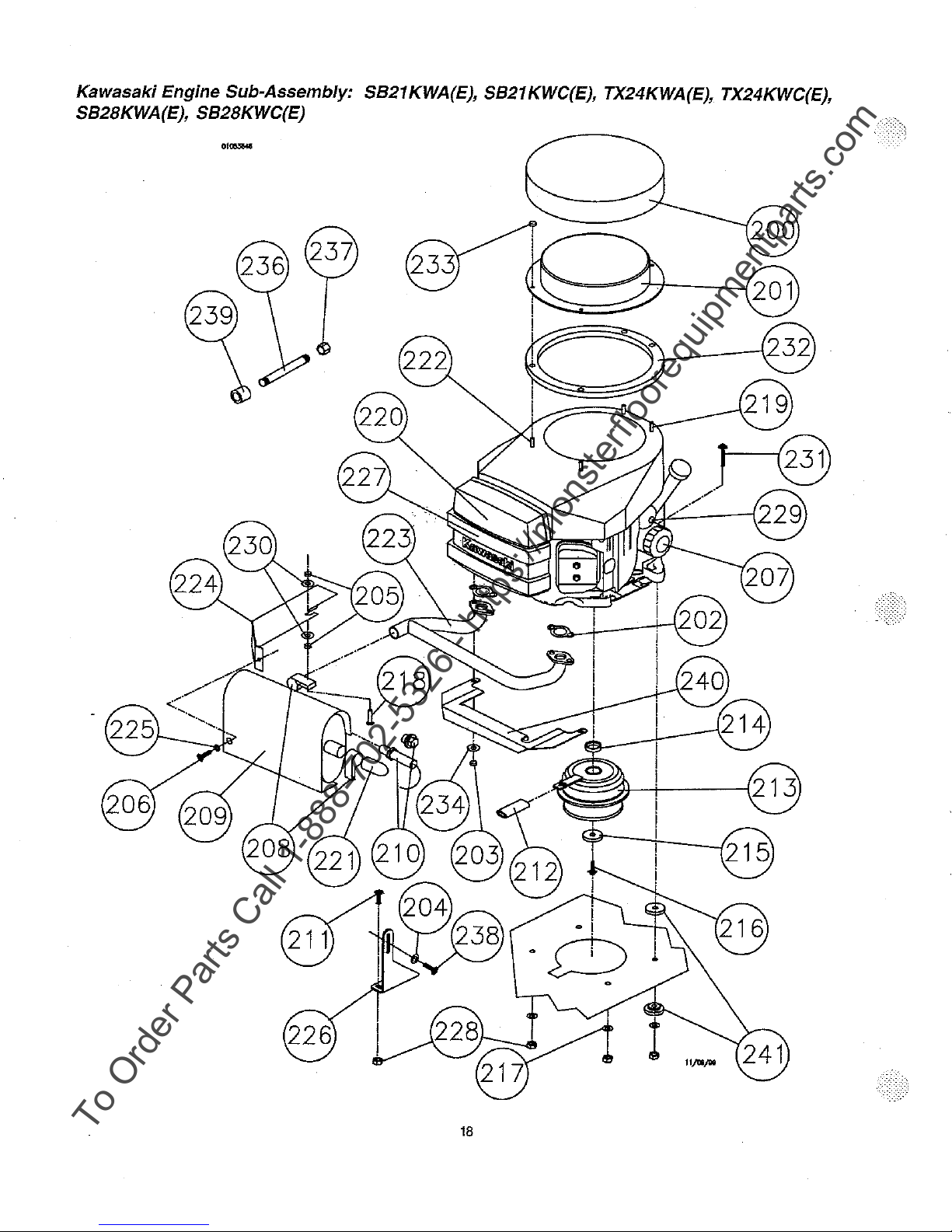
Kawasaki Engine Sub-Assembly and Parts List ...........................................................................................................................
Handle Sub-Assembly and Parts List .....................................................................................................................................•...... 20
Air
Filter
............................................................................................................................................................... 6
Hose
and
Connections ................................................................................................................................................. 6
Maintenance .................................................................................................................................................................. 7
AND
PARTS
LIST
s
10
11
12
14
18

To Order Parts Call 1-888-702-5326 - https://monsterfloorequipmentparts.com

I.
To Order Parts Call 1-888-702-5326 - https://monsterfloorequipmentparts.com
PROPANE MACHINE SAFETY
A. Purpose
The accepted demand for and use of propane powered floor machines underscores the need for responsible manufacturers
users
to
stress the importance
use of propane powered floor machines.
In
addition, we recommend operators
for the safe operation
Technician Training.
of
safety. This manual is designed to provide the information
of
propane powered floor machines complete a program of training and certification
of
this equipment. Contact Pioneer Eclipse
you
at
1-800-334-2246 for informaflon
need to ensure proper and safe
on
Factory Certified
and
B. Refueling
Propane cylinders should only be filled by
an
upright position
at
least five feet (1.5
The National Fire Protection Association (NFPA) Standard for Storage
propane use. A copy of this publication is available through the National Fire Protection Association
(1-800-334-3555).
C.
Safety
Pioneer Eclipse engineers and manufactures machines utilizing U.L. (Underwriters Laboratories)
Association) approved components where possible. When a tag or tags bearing the U.L.,
to the machine,
having met all
In
some cases, the tag will be affixed to a particular component. This means that only the component
recognition for the following parts
you
use only machines meeting the above minimum
Even
though propane powered floor machines manufactured
(TWA) standard for noise,
D.
Use
All machines manufactured by Pioneer Eclipse come with a detailed Operator's Manual. Safety dictates that before using any new
equipment,
E.
Canadian Safety Regulations
1.
A sign indicating "NO SMOKING" shall
sign required
2.
When the cylinder
for short periods of time such
3.
The requirements of
4.
A floor maintenance machine shall only be used
a)
provided with continuous mechanical ventilation that removes the products
300 CFM for each 10,000 Btuh input or traction thereof.
b)
provided with natural ventilation of not less than 300 CFM for
maximum of one quarter air exchange per hour for the net building volume.
5.
The owner
manufacturer of the unit
6.
The owner of a floor maintenance machine shall ensure that the unit is maintained in accordance with the manufacturer's
recommended maintenance procedures
for a period
7.
Before transporting a floor maintenance machine, the cylinder shall
cylinder shall be located
and
in
Engineering
it
of
and
Care
it
is
important
in
of
of
Storage
in
a secure, tamper-proof, steel
m)
of
space between the cabinet and the nearest building opening (door or window).
indicates that the entire machine has been researched, tested,
their safety criteria.
to
Clause 10.12.3
is
attached to the floor maintenance machine for
1.10.1
a floor maintenance machlne shall ensure that the operator has participated in a course authorized
two years.
of
Fuel Cylinders
an
authorized propane dealer. When not
mesh
storage cabinet. This cabinet may be located next
and
is
important: fuel cylipders, couplings, regulators,
r6qUii"ements.
by
Pioneer Eclipse meet the 0.S.H.A. Time Weighted Average
we
still recommend that hearing protection be worn by the operator.
read
and
understand the Operator's Manual. We strongly recommend this practice.
be
permanently displayed
of
CAN/CGA-B149.2-M91, Propane Installation
as
rest stops, washroom or meal stops.
(e)
and
(g)
do
not
apply in industrial buildings.
in
buildings:
on
the safe handling of propane and the sate operation of the machine.
in
a safe operating condition and the owner shall maintain a record
in
a well ventilated space.
at
the storage area. The sign shall be
use,
the operator shall not leave the unit unattended except
each
10,000
be
securely fastened with the system valve closed,
in
Handling of
and
and
Code.
of
combustion
Btuh
use,
LP
is listed by
fuel lines. We strongly recommend that
input or fraction thereof, based
they
shOuld
always
be
stored outside
to
the building but
Gas is the appropriate authority for sale
in
Qµincy, Massachusetts
and
C.G.A. (Canadian Gas
CE
and/orC.G.A. insignia is/are affixed
one
or both organizations as
is
listed. Component
in
accordance with the
to
the outdoors of not less than
of
the maintenance
on
by
a
the
and
in
with
the
F.
Test
for
Operator-Ear
Pioneer Eclipse measures and rates the operator-ear sound pressure level for hand-guided floor treatment and floor
cleaning machines for industrial
• Outdoor test area consists of a flat open space tree from effects
ft) from the center of the test surtace. Indoor tests are conducted
Sound
use.
Pressure
All tests are perlormed
Level
in
accordance with European Machinery Directive (98/37/EC).
of
signboards, buildings or hillsides for
in
a semi-anechoic or sound_deadening
at
least 15m (50
room.

• The test surtace is a single sheet of floor covering at least 1 m (3.3
To Order Parts Call 1-888-702-5326 - https://monsterfloorequipmentparts.com
order to not affect the sound reading, the observer taking readings is at least 2 m (6.6
standing directly behind the operator.
• All machines are tested while stationary and centered
the test is conducted with the machine at maximum engine or motor speed as
• The operator is located
machine, 1,68 m (66 in) above the test
cm
(8
in)
to
the rearmost point of the handle, with the handle in the most forward position.
• The sound !eve! meter
repeatable sound level observed during the test at each microphone position
G.
Test
for
Hand-Arm Vibration
Pioneer Eclipse measures and rates the vibration at the machine-hand contact surface of hand-guided machines that are
provided with handles in accordance with European Machinery Directive (98/37/EC).
• The Test area consists of a flat open floor area that allows the machine to be operated normally.
• The transducer is mounted firmly at a point halfway along the length of the handle where the handle would normally be held.
• Machines are tested while stationary, with all mechanisms necessary for the equipment to pertorm its intended functions
engaged
specified
• The measurements are recorded from the dominant axis.
II.
MACHINE PREPARATION
and the traction drive
by
the manufacturer of the subject machine.
in
the normal operating position with the microphone or meter supported independent
surtace,
is
observed for a minimum
at
the
Grip
in
neutral (if applicable). The machine will be tested
on
the test surface. With the traction drive
25
cm
(10 in) to the right and left centerline of the operator's position, and 20
of
5 seconds or until a stabilized reading
Surface
fl)
wider and longer than the equipment being tested. In
fl.)
from the equipment being tested, or
in
specified by the manufacturer.
is
recorded and documented.
of
Hand-Guided Machinery
at
maximum engine or motor speed as
neutral (where applicable)
is
obtained. The maximum
of
the
Adding
A.
When the Burnisher is shipped by
machine
The
machine
When filling a "dry" burnisher or changing oil,
changing
necessary but DO NOT OVERFILL!
operator's
-c1oth,
then insert dipstick into tube without screwing in. Check oil level. ALWAYS make sure
when
checking
B.
Connecting
Connect the RED positive battery cable FIRST.
Connect the
C.
Adjusting
The burnisher handle adjusts for comfort and optimum control. Height may be changed
D.
Filling
Pioneer Eclipse uses the
also listed by U.L. Filling should be done ONLY by a qualified propane dealer. FILL THROUGH THE SERVICE
(See page 13) A properly filled cylinder should not exceed 80% of the rated capacity.
DO NOT attempt safe-fill cylinder repair. Return the cylinder to your propane dealer
regulations prohibit shipping of cylinders after the cylinder has been filled with propane.
E.
Installing
Align the slot in the top flange
the
toggle assembly to the cylinder band. Adjust the toggle assembly by screwing
Connect the fuel hose coupling
is
not
cross threaded and check for leakage by noting any propane odors immediately after cylinder is connected. (It is sometimes
easier to install
TO
REMOVE THE SAFE-FILL CYLINDER, reverse above procedure.
Oil
3.8
overland
with
US
pints
to
be
shipped without oil.
is
also
the
oil
filter,
manual.
oil.
shipped
or
IMPORTANT: When checking oil
the Battery
BLACK
negative battery cable LAST.
the Handle
the Safe-Fill"' Fuel
20
lb. capacity aluminum safe-fill cylinder which meets the D.O.T. 4E240 standards. These cylinders are
the
Safe-Fi/I'M
of
the cylinder with the locating pin on the machine. Strap the safety fill cylinder in place
to
the service valve by turning to the right (clockwise). HAND TIGHTEN ONLY. Make sure coupling
if the connection to the service valve
freight,
the
battery
(1,8 L)
ALWAYS
the.correct arilOunt of oil
disconnected.
for
the
Kawasaki
when
the
CHECK OIL BEFORE USING THE MACHINE. Refer
on
Cylinder
Fuel Cylinder
is
made before strapping the cylinder
is
in
the engine.
engine
add
no
more than 1.5
oil
filter
is
changed, then check the dip stick
Kawasaki models, remove oil filler cap and clean dipstick with clean
if
repair is necessary. Please note that
in
or out
Always
connect or change cylinders in a well ventilated area.
Air
freight
quarts
the
machine
to
suit the individual operator. (See page 8)
in
orderto keep the tank firmly secured.
in
place.)
shipments require the
(1,4 L)
when
not
in
the fill cap. Add oil if
to
the
engine
is
sitting
level
VALVE
ONLY.
0.0.T.
by
clamping
2

Ill. OPERATING INSTRUCTIONS
To Order Parts Call 1-888-702-5326 - https://monsterfloorequipmentparts.com
,j
A. Starting
1.
Check oil and fuel levels
2.
Check and clean engine air filter
NEVER RUN
FILTER. (See "Scheduled Maintenance")
3.
Check
4.
Turn propane service valve counterclockwise to open.
NOTE: ALWAYS OPEN
FLOWCHECKVALVETO
5. Allow machine to tilt backward (pad off floor) and move
6. Engage starter
ignition switch return to the run position (Do
(NOTE: Do not engage starter for more than 1 O seconds. Allow a 60 second cool-down period
cycle.)
7.
SAFE
(The machine
as
the machine
Instructions
CONTINUOUSLY
carburetor air filter. Change
SLOWL
by turning the key-switch to
SENSE
ONLY:
may
be operated during this
is
running safely.
FOR
YTO
ENGAGE, LIMITING FUEL FLOW.
After engine starts, a GREEN light will flash for a 3 minute
MORE
if
necessary. (See "Scheduled Maintenance")
ALLOW
THAN
PRESSURE
the
starting position
not
turn off).
warmMup
1 HOUR WITHOUT
TO
EQUALIZE IN HOSES. OPENING QUICKLY
the
throttle to the
for
Wait
approximately 5 seconds and
period.) After the
SLOW
approximately 5 seconds. If the machine fails to start, let the
warmMup
CLEANING
position.
B. Operation
After engine
Lower the burnishing head to the floor while moving the
CAUTION! DO
OR
FLOOR FINISH
To
stop burnishing, push down on handle to raise th~ burnishing head off the floor.
SAFE
muffler.
Upon
continuously
the
green
machine
WARNING!
of
proper
has
SENSE
starting
light
will
ventilation
started, allow approximately
NOT
RUN
THE
BURNISHER
MAY
OCCUR.
ONLY:
the
unless a warning
shut
Catalytic
NOTE: This burnisher is equipped with the SAFE SENSE emjssjon monitoring system and catalytic
engine,
will
down
the
go
out
and
within 1 minute.
mufflers
during
this
GREEN
is
being
the
RED
require a few
warm-up
30
WITHOUT
LED
light
sl.gnaled.
LED
period!
secoads.
will
light
will
minutes
f0rthe
engine to warm up. Advance the throttle to operating speed.
!Tlachine forward slowly.
MOVING.
flash
If
the
start
to
IF
ALLOWED
for 3 minutes
carbon
monoxide
flashing.
warm
up
before
during a warm-up
When
TO
in
the
the
red
effectively
OR CHANGING ENGINE DUST
MAY
CAUSE
try
again for another 5 seconds.
for
each 1 O second start-up
warm-up
cycle, the green light will remain on as
RUN IN
exhaust
light
cycle
of
the
SAFE
ONE
SPOT
DAMAGE TO
period.
becomes a continuous
removing
After
that,
is
approaching a hazardous
harmful
SENSE
THE
it
will
red,
emissions.
be
THE
system.
Jong
FLOOR
on
level
the
Make
sure
C.
Stopping
To
stop the engine, close the service valve
used up).
D.
Installing/Changing
1.
With engine
accomplished by pushing down on the right handle grig with some force while the machine
machine
2.
Remove centering device (if used) and carefully pull old
3.
CAREFULLY
NOTE: A damaged
4. Pull center from
center ring.
5. Press pad onto velcro.
6.
Return machine to upright position.
the Machine
After
the
engine
OFF
and in the operating position, turn the machine over
over
on
INSPECT
pad
new
stops,
turn
Burnishing
the
carburetor
THE
PAD
holder
rotating
pad, center pad on pad holder and secure with centering device (if used) or tuck the center
on
the fuel cylinder by turning it clockwise. (The engine will stop when the fuel in the lines
the
key
switch
to
the
"OFF"'
position.
Failing to turn the
key
OFF
may
drain
Pad
on
side
as
HOLDER
at
high speeds
this
will
FOR
may
the RIGHT
fill
the
carburetor
pad
off the velcro pad holding material.
CRACKS
be
OR
an extreme hazard if it should come apart.
with
DAMAGE!
3
or
starter side. This can
is
tilted back.
oil.)
Replace
if
Be
necessary.
be
sure
under
easily
not
the
to
the
battery.
turn
the
plastic
is

E.
To Order Parts Call 1-888-702-5326 - https://monsterfloorequipmentparts.com
Storage
Only authorized, trained personnel should have access to propane cylinders and machines.
1.
Remove
Section
Please consult your local Fire Marshal
2. Store machine away from objects that may fall and damage
3. Never store burnisher or fuel cylinders near
4.
Make sure burnisher is cleaned properly before storing.
5.
Never store burnisher with cylinders installed, or store spare cylinders
F.
Repacking
1.
Use shipping and package
information attached to packing slip to
repack machine.
2.
Store
Temperature not
propane
5
or
Subsection
machine
fuel
cylinder
in
a dry location.
to
exceed S0°C.
9.5.2
when
not
in
use and
of
CAN/CG A 8149.2. Do
to
ensure that you are
an
open flame or heat producing devices.
store
not
it
outside
release
in
it.
in a storage cage
or
bleed
propane
compliance with local fire codes.
in
an enclosed van or trailer.
in
accordance
inside
the
with
building.
NFPA
G.
Transportation
When
transporting a propane powered floor burnisher with the fuel cylinder installed,
be
with the service valve closed and the burnisher should
should
be
securely
with cylinders installed, or store spare cylinders in an enclosed van
for
overfilling
outside
in a
fastened to avoid movement and damage.
before
safe
transporting them. If overfilled, correct before loading them in
area using the bleeder valve.
secured in the vehicle. Any propane fuel cylinders not installed
The
service valves should
or
SCOTCH BLOCKS
the
cylinder should
be
closed. Never store burnishers
trailer. It is a good practice to check propane cylinders
the
vehicle
by
be
securely fastened
venting the excess propane
4

IV.
To Order Parts Call 1-888-702-5326 - https://monsterfloorequipmentparts.com
SCHEDULED MAINTENANCE
Following proper scheduled maintenance procedures will provide years of uninterrupted service.
KAWASAKI ENGINE
or
ITEM
TYPE of SERVICE
Engine Oil
Oil Filter
Engine Dust Filter
Carburetor Air Cleaner
Clean Pre-Foam Element 2
Belt
Fuel Hose
& Connections
Cooling Fins
Check Level 2
Change
Change 4,5
Inspect
Clean/Change 1,2
Inspect 2
Clean/Change Element
Inspect
AdjusVReplace As Required
Inspect
Replace
Clean 2
REGULAR SERVICE PERIOD
(Periormed At Indicated Hour Intervals)
Break
In
Each
25 hrs.
8 hrs. Use
2,4,5 2,4,5
1
•
2
2
2
2
M Signs of Wear are Present (3,5 below)
50 hrs. 100 hrs.
2,4,5
(5
below)
300 hrs.
Burnishing Head Assembly
Pad Holder
Inspect
6
Inspect When Chanaina Pads
Replace If Cracks Appear (2 below)
& Connections
Bolts
Inspect
Tighten
6
6
Spark Plug Clean/Replace 5,6 4,5
Battery
Exhaust Emissions
Check
& Battery Cables Inspect 2
Check 3,5
& Adjust Valve Clearance 5,6,7
Retorque Heads
1.
Perlorm
2. Refer to Section
3.
These
4. Refer to Engine Manufacturer's "OWNER'S MANUAL" for recommended replacement.
5.
Always enter maintenance performed
6.
Routine
7.
Refer
after
each
items
should
maintenance.
to
Engine
hour
of
operation.
V"GENERAL
be
serviced
Service
Manual.
MAINTENANCE PROCEDURES".
by
an
authorized
in
"SERVICE LOG BOOK".
Pioneer
Eclipse
Service
Center.
5

V.
To Order Parts Call 1-888-702-5326 - https://monsterfloorequipmentparts.com
GENERAL MAINTENANCE PROCEDURES
A.
Fuel
System
The
fuel system
for
system
1.
Adjusting
NOTE:
The
authorized personnel, trained and certified in
N.F.P .A.
Gas
engine
2.
Engine
The
engine dust filter should be
Squeeze
engine
works
from vacuum created
flow to the carburetor once the
the
Regulator
regulator and carburetor have been factory pre-set and should not require any modification. Only Pioneer Eclipse
58
8-1.4 states, "In the interest
fuel system shall
Dust
Filter
out
the excess water (do not wring). Allow the filter to air dry.
to
overheat. Also, it may cause
be
properly trained in the necessary procedures."
cleaned
by
the engine running. Turning the fuel cylinder service valve ON pressurizes the
engine
starts
to
crank.
propane
of
safety, each person engaged in installing, repairing, filling, or otherwise servicing an LP-
each
the
systems, should
hour
and after each use
exhaust
emissions
modify
or
adjust the system
by
shaking out the dust and then rinsing with mild detergent.
Failure
to
elevate
to
maintain
to
harmful levels.
or
a clean
its setting.
engine
filter
will
cause.the
3. Carburetor
a. Loosen wing
b. Remove foam pre-cleaner and
c.
Clean foam pre-cleaner using
ct.
Clean filter seal, making sure
e.
Inspect paper element. Replace if dirty, bent
f.
Install the clean paper element, pre-cleaner, air filter. cover and wing nut.
SAFE
SENSE
emissions
4.
Hose
a. Inspection
(1) Inspect hoses
(2) Check for gas leaks by spreading soapy water solution around all
and the fuel system is pressurized.
Air
Filter
nut
on top
of
the air cleaner cover.
paper
filter element.
the
ONLY:
NOTE:
same procedure as
no
dust is allowed in,!he carburetor inlet.
or
Failure
to
service
#2
damaged.
the
carbu.retor
and cause the SAFE SENSE systerri t~-shut the-engine
and Fuel Connections
for
abrasions and other signs of wear; replace all worn
above.
air
cleaner
b. Fixing Leaking Joints
(1) Uncouple
the clean joint.
(2) Recouple
(3)
Recheck
turned
bad
joint and clean it. Then apply pipe sealing compound (Loc-Tite Pipe Sealant with Teflon or equivalent) to
the
joint finger tight plus 1/2 tum.
for
leaks
using
soapy
water
on and
the
fuel system pressurized.
solution.
Watch
for
bubbles
may
produce
down.
or
damaged hoses.
the
connections while
at
the
joint
with
excessive
the
service valve is turned ON
the
fuel
cylinder
carbon
monoxide
service
valve
6

B.
To Order Parts Call 1-888-702-5326 - https://monsterfloorequipmentparts.com
Engine Maintenance
1,
Cooling Fin Maintenance
a.
Remove
b.
Clean
c.
Reinstall
2. Head Bolt Maintenance
a.
Refer
3.
Changing
a.
Run
by itself. Turn the key OFF. (Failing to turn the key OFF
SAFE SENSE ONLY: NOTE:
b.
Locate
c.
Remove
d.
Allow
e.
Replace
t.
Remove oil fill cap. Slowly add no more than 1 1/2 quarts (1,4
quarts
g. Check oil level with dip stick in oil fill cap. Add additional oil if necessary.
DO NOT OVERFILL AND NEVER RUN
IMPORTANT:ALWAYSMAKESURETHEMACHINEISSIITINGLEVELWHENCHECKINGOIL.
h.
Replace fill cap. Hand tighten only.
the
the
all
to
Engine
the
engine
the
the
oil
to
the
(1,8
cooling
oil
blower
housing
fins
housings
Manufacturer's
for 5 minutes
oil
drain
pipe
cap
by
turning
dra!n
completely
cap
by
turning
L)
when
the
and
as
necessary
and
shrouds.
to
warm
Must
located
it
with a wrench.
into
clockwise.
oil
filter
other
using
Service
oil,
be
running
on
the
the
receptacle.
is
changed.
ENGIN~
cooling
compressed
Manual.
then
stop
above
right
shrouds.
side
Refer
LOW
the
engine
may
2150 RPM
of
the
to
engine
ON
Olli
air
or
pressure
by
closing
run the battery down.)
or
SAFE SENSE
machine.
L)
of motor oil when not changing the oil filter, or 1 3/4
Owner's
washer.
the
Manual
fuel
service
will
for
valve,
allowing
shut
the
engine
recommended
down.
oil.
the
engine
to
stop
C.
Belt Maintenance
,nside V-Groove Idler System --
To
inspect
the
belt
it
is
necessary
can
easily
be
accompllshed
badly
cracked
To check
Always
To change belt:
1.
Turn
2.
Remove the pad holder
counterclockwise.
3.
Use the 3/4" wrench to turn the end of the spindle shaft on top
4.
Finish
5.
Check engine pulley for correct alignment with the spindle pulley. Check hardware attaching pulleys for proper tightness.
6.
Install the new belt onto the engine pulley.
7.
Reinstall the new belt onto the spindle pulley using the 3/4" wrench
placed on the idler pulley.
8.
Reinstall the pad holder onto the spindle shaft.
9.
Turn
10. Check belt
or
worn
for
the proper tightness squeeze the belt together. The belt should depress between 1/4" (,6 cm) and 1/2" (1,3 cm).
use
the
recommended
the
machine
removing
the
machine
over
the
upright
for
correct operation. Check all hardware
by
pushing
it
should
belt
on
the
by
holding the end of
belt
from
the
in
the
be
right
5821
to
turn
the
down
replaced.
size.
side.
engine
pulley,
burnishing
KWA(E)IKWC(E}, SB28KWA(E}IKWC(E)
machine
on
the
position.
over.
The
machine
the
handle
grip
with
shaft on the top of the machine with a 3/4'' wrench and turn the pad holder
of
the machine while removing the old belt from the spindle pulley.
if
necessary.
for
proper tightness.
should
be
turned
to
the
right
some
force
while
the
machine
to
turn the spindle clockwise. Make sure the belt is correctly
is
side
tilted
(starter
back.
side).
If
the
This
belt
is
7

V-Groove Idler System -- TX24KWA(E), TX24KWC(E) Only
To Order Parts Call 1-888-702-5326 - https://monsterfloorequipmentparts.com
To
inspect
the
belt
it
is
necessary
can
easily
be
badly cracked
To
check for the proper tightness squeeze the belt together. The belt should depress between 1/4 and 1/2 inch (,6 - 1,3 crn).
To
tighten
accomplished
or
worn it should be replaced.
follow#
9 of this section.
by
pushing
to
turn
the
down
machine
on
the
over.
handle
The
grip
machine
with
some
should
force
be
turned
while
the
to
the
machine
right
is
side
tilted
(starter
back.
To Tighten Belt
Push
belt
outer
edge
tensioner
of
deck
to
add
bolt
more
toward
tension.
Deck Edge
---
To Change Belt:
1. Remove the pad holder
counterclockwise.
2. Use
the
3/4" wrench to
3.
Finish
removing
4.
Check
engine
pulley
5. Install the
6.
Reinstall
placed on
7.
Reinstall
8.
Turn
9. Check for propertightness. Tighten the belttension by pushing
tighten with a 9/16" wrench. Loosen the belt tension by pushing
a 9/16" wrench.
10. Operate
new
belt onto the engine pulley.
the
new
the
idler pulley.
the
pad holder onto the spindle shaft.
the
machine
for
20
minutes
the
belt
for
belt
upright
by
holding the end of the shaft on the top of the machine with a 3/4" wrench and turn
tum
the end of the spindle
from
the
engine
correct
alignment
onto
the
spindle
in
the
burnishing
and
check
belt
pulley,
pulley
tension.
if
with
the
using
position.
Adjust
shaffon
neCessary.
spin91e
the
3/4"
if
top of
p~lley.
wrench
necessary.
the
machine while removing the old belt from the spindle pulley.
Check
hardware
to
turn
the
the
belt tensioner bolt toward the left side of the machine and
the
belttensioner bolt in the opposite direction and tighten with
attaching
spindle
pulleys
clockwise.
for
Make
the
proper
sure
the
pad holder
tightness.
belt
is
side}.
If
the
belt
correctly
This
is
D.
Adjusting the Handle
Insert lever bolt through handle
bracket
and
hinge
bushing
locate
handle
in
operating
to
position.
8
Handle
OJ>erating
Position*
Lever Bolt
Bracket
Hinge Bushing
Shinning
Position

E.
To Order Parts Call 1-888-702-5326 - https://monsterfloorequipmentparts.com
Battery Maintenance
The
battery
supplied
When
battery
doubt, contact Pioneer Eclipse Customer Service at 1-800-367-3550. To replace:
1.
Remove
2.
Raise
3.
Disconnect
4.
Remove battery hold-down clamp.
5.
Lift old battery out and replace with new battery.
6.
Reinstall hold-down clamp. NOTE: DO NOT OVER TIGHTEN
to
7.
Connect the RED positive battery cable first.
Connect the
the
battery
rupture.
with
replacement
propane
battery
BLACK
fuel
cover
to
cables
negative battery cable last.
this
machine
becomes
cylinder
expose
from
and
Replacement
is a sealed
necessary,
from
the
battery.
terminals.
gelled
the
replacement
machine.
Always
electrolyte
disconnect
maintenance
should
the
BLACK
HOLD-DOWN
have
free
the
cable
type.
same
specifications
first.
CLAMP.
lt
never
should
need
servicing.
as
the
original.
Doing so may cause the battery
If
in
Dispose of
old
battery in the proper manner.
SAFETY'.
INSTRUCTIONS
RECHARGEABLE BATIERY
! DANGER!
ALL
BATTERIES CONTAIN CORROSIVE ACIDS AND
PRODUCE EXPLOSIVE GASES DURING RECHARGING
GAS EXPLOSION
CAN CAUSE
BLINDNESS
OR
SHIELD EYES
INJURY
BATTERY ACID
CAN CAUSE
BLINDNESS OR
SEVERE BURNS
* Do not make direct contact between battery
terminals as this can cause
an
explosion or
fire.
* Batteries should not be stored discharged.
* Only adults should recharge batteries.
* Keep charger away from children.
* Use only the charger provided by the equip-
ment manufacturer.
* Do not recharge batteries upside down.
* Charging produces explosive gases. Charge
battery
sparks, flames and smoking.
* Disconnect charger
in
a well ventilated area away from
from
batteryafter24 hours.
INTERNAL
TAKE MILK, EGG WHITES,
AND WATER.
DO
NOT
INDUCE VOMITING
CALL PHYSICIAN IMMEDIATELY
EXTERNAL
FLUSH IMMEDIATELY FOR
15 MINUTES IF ACID GETS
IN
EYES
OR
ON SKIN
9

VI.
To Order Parts Call 1-888-702-5326 - https://monsterfloorequipmentparts.com
TROUBLESHOOT/NG
SYMPTOM
1. Hard to start
2.
Will not start
3.
Engine lacks power
4.
Smell of burned rubber
5.
Machine vibrates
6.
Machine "Bogs Down" when in use
7. Machine pulls to one side
8.
Engine stops running
POSSIBLE CAUSES
Opening propane cylinder too quickly (OPEN SLOWLY)
Spark plug
Blown head gasket
Insufficient vacuum
Coil, air gap needs adjusting
Low oil
Incorrect spark plug gap (Gap should be .025)
No fuel
Blown head gasket
Insufficient vacuum
Defective spark plug
Defective coil
Dirty air filter
Low oil
Fuse blown in Safe Sense
Wires broken or disconnected
Leaking head gasket
Insufficient vacuum
Governor needs adjusting
No compression
Check air filters
Belt out of adjustment
Loose bolts
Pad not centered
Operator ls bearing down too hard
Dirty air filters
Check for bent wheel bracket
Dirty air filter
High exhaust emissions
Out of fuel
Low oil
or
head bolts loose
w worn rings
VII.
DRAWING AND PARTS LIST
Safe-FilJ'M Cylinder Head
Layout
10
Bleeder
Valve
Liquid
Sight
Pressure
Relief
level
Gauge
Valve

Wiring Diagram/Schematic
To Order Parts Call 1-888-702-5326 - https://monsterfloorequipmentparts.com
Oil
PRESSURE
swrrci;
for
Machines with Safe Sense
ELECTRICAL SCHEMATIC
SAFE
SENSE
.....
(fASflCIIIG)
""'
REV.
8
#iring
Diagram/Schematic
for
Machines
SEALED
without
Bl.TIER'!'
Safe Sense
(JX)
.«!OVOC
BLOCl<ING
SAMP
DIODE
11

Deck
To Order Parts Call 1-888-702-5326 - https://monsterfloorequipmentparts.com
Sub-Assembly: 5821KWA(E), SB21KWC(E)
12

Deck
To Order Parts Call 1-888-702-5326 - https://monsterfloorequipmentparts.com
Sub-Assembly Parts List:
5821
KWA(E},
5821
KWC(E)
REF# PART#
300
301
302 NB3350
303 MP8038
304 TB1012
305 NB5700
306
307
308
309 MP4775
310
311
312
313
314
315
316
317
318
319
"''..10
1 NB6863
322
323
324
325
326
327
328
329
330
PD006021
NB9308
MP8310
MP032600
NB3275
MP7245
NB3260
NB6111
NB3265
MP9420
MP012801
MX1010
NB2643
MP9613
NB6525
NB003100
NB5000
MP9610
NB6044
NB9269
NB5282
NB3450
MP007900
SA003900
MP481001
DESCRIPTION
Pad,
21
",
Blue Blend
Bolt, Button HD 1/4"-20UNC x 1
Washer, Flat 1 /4"
Belt, BX-38
Flexi-Swivel
Washer, S.S
Velcro Stud
Padholder,
Nut, Lock 1/4"
Tensioner, Belt
Spindle Asm., w/BK65 Pulley
Nut, Lock 5/16"-18NC
Washer, Spring Lock 5/6"
Nut, Lock 5/16" -18
Wheel, w/Bracket 5"
Wheel, Caster Rear
Moulding, Bumper
Rivet, Pop 1/8" x 1/4"
Wire, Ground Hour Meter Assembly
Grommet 1/2" x 3/8" x 1"
Nut, Jam 3/8" x 16
Bolt, Hex HD 1/2" x 1" NC
Bolt, Carriage 5/6"-18 x 1"
Meter, Hour (RND)
Screw, Cap 3/8" x 1 1 /4"
Washer, Flat 7/16"
Bolt, Hex HD 5/16"-18 x 1"
Washer, Flat, 3/8
Deck, Resale, 21"
Padholder,
Block, Wheel, 14GA
..
755 x 1.005 x .060
21
",
Complete Asm.
21
",
W/Studs Only
Q1Y
1
6
12
1
1
50
1
6
1
1
3
2
1
4.8 Ft.
11
1
1
4
1
1
1
4
3
1
1
13

Deck
To Order Parts Call 1-888-702-5326 - https://monsterfloorequipmentparts.com
Sub-Assembly: TX24KWA(E), TX24KWC(E)
01M3601
14

Deck
To Order Parts Call 1-888-702-5326 - https://monsterfloorequipmentparts.com
Sub-Assembly Parts List: TX24KWA(E), TX24KWC(E)
REF# PART#
301
302
303 NB9308
304
305
306
307
308
309
310
311
312
313
314
315
316
317
318 NB6110 Washer, Lock, 1
319 NB9680 Bolt, Button HD, 1/4-20 x 1-1/2 2
320
8>'1
323
324
325 IN7800
326
327 NB6863
328
329
330
331
332
333 NB9670 Washer, 16M X 28M X 3M, Zinc
334 NB9675 Screw, 5/8-18 x 2-1/2, Cap
335 MP4770
336 TB2040 Guard, Belt, Turbo
337
338
339 NB2463 Screw, Set, 5/16-18 x 3/8, Hex Socket
340
341
342
MP8310
TB1210
NB3350 Washer, Flat, 1 /4
NB3275 Nut, Lock, 1/4
SA009000 Padholder, 24", Vortex, W/Studs only 1
NB5700 Washer, S.S
NB2643
TB9610 Hour Meter
PD006124 Pad, 24" Blue Blend-VTX 1
MP012700 Retainer, Pad, Center-Lok
NB6525 Grommet 1 /2" x 3/8" x 1" 1
NB52816 Bolt, Button HD, 1/4-20 x 1/2
NB003200 Bolt, Hex, HD, 1/4-20 x 5/8 2
MX1035 Bolt, Hex HD, 10-24 UNG 2
TB2489
MP027500
TB2060 Bag, Dust, Turbo
TB2061
TB2050
MP8150 Belt, B-49
TB7230 Spindle Assembly
MP9415 Wheel,
NB9269 Washer, Flat 7/16"
MP7802
MP8300 Velcro, Hook, 1"
TB000100
MP9613
MX1075 Lock Washer
NB1588
MP4805 Spacer
MP007800
MP024600
DESCRIPTION
Velcro Stud
Flexi-Swivel
Bolt, Button HD, 1/4-20 x 1
..
755 x 1.005 x .060 1
Rivet, Pop 1/8" x 1/4"
II
Skirt, Turbo
Caster, 3 1/2 Swivel, Pl~te Mount 1
/4
Hook, Dust Bag
Guard, Dust Bag, Turbo
Pulley
5"
Bolt, Hex HD 1 /2" x 1" NC
Key,
1/4 x 1/4 x 1-1/2
Spacer, Tensioner, Turbo 1
Ground Wire, Hour Meter
Tensioner, Belt
Bolt, Hex HD, 3/8 X 2-1/2 NC
Deck, Resale, 24"
Padholder, 24" Vortex, Complete Asm.
QTY
76
10
16
10
2
1
1
1
2
1
1
1
2
4
4
6 ft.
4
2
1
1
1
1
1
1
15

Deck
To Order Parts Call 1-888-702-5326 - https://monsterfloorequipmentparts.com
Sub-Assembly: SB28KWA(E}, SB28KWC(E)
010535Cl!I
~
I
'
01/0fl/H
16

Deck
To Order Parts Call 1-888-702-5326 - https://monsterfloorequipmentparts.com
Sub-Assembly Parts List: SB28KWA(E}, SB28KWC(E)
REF#
400
401
402
403
404
405 NB5700 Washer, S.S
406 MP8310 Velcro Stud
407
408
409
410
411
412
413 NB3265 Nut, Lock 5/16"-18 x 1 3
414 MP9420
415
416 MP4810
417
418
419
420 NB6525 Grommet 1/2" x 3/8" x 1" 1
422
423 NB5290 Bolt, Hex HD 5/16"-18 x 1-1/2 3
424 NB6863
425
426 MP9610 Meter,
427 NB6044
428
429
430
431
432
433 SA004000 Padholder, 28", W/Studs only
PART#
PD006028
NB9319 Bolt, Button HD 1/4"-20UNC x 1.25 6
NB3350 Washer, Flat 1 /4" 12
MP008900
TB1210 Flexi-Swivel
MP032500 Padholder, 28" Complete Asm. 1
NB3275 Nut, Lock 1/4" 6
MP4775
MP7240 Spindle Asm.
NB3260 Nut, Lock 5/16"-18NC
NB6111
MP012801 Wheel, Caster Rear 1
MX1010 Moulding, Bumper
NB2643 Rivet, Pop 1 /8" x 1 /4"
NB3450 Washer, Flat 3/8 1
MP012700 Retainer, Pad
NB003100 Nut, Jam 3/8" x
NB5050 Bolt, Carriage 5/6"-18 x 1-1/2 1
NB9269 Washer, Flat 7/16"
MP9613 Ground Wire, Hour Meter 1
MP008200 Deck, Resale, 28" 1
MP481001 Wheel Block, .07 4 Thk. 2
MP481002
DESCRIPTION
Pad, 28", Blue Blend
Belt, BX-52
..
755 x 1.005 x .060
Tensioner, Belt 1
w/
BK-90 Pulley 1
Washer, Spring Lock 5/6" 2
Wheel, w/Bracket 5" 2
Wheel Block
16
Bolt, Hex HD 1 /2" x 1"
Hour
(RND) 1
Screw, Cap 3/8" x 1 1/4"
Wheel Block, 1 /8 Thk. 1
NC
QTY
1
1
70
11
1
4
4
17
Kawasaki Engine Sub-Assembly:
To Order Parts Call 1-888-702-5326 - https://monsterfloorequipmentparts.com
S828KWA(E), S828KWC(E)
........
5821
KWA(E),
5821
KWC(E), TX24KWA(E), TX24KWC(E),
18

Kawasaki Engine Sub-Assembly Parts List: SB21KWA(E}, SB21KWC{E), TX24KWA(E},
To Order Parts Call 1-888-702-5326 - https://monsterfloorequipmentparts.com
TX24KWC(E}, SB28KWA(E}, SB28KWC(E)
REF#
200
201
202 KA
203 KA317R0800 Nut,8mm
204 KCX2578
205 NB3260
206 NB3001
207
208
209
210 MP018000 Oxygen Sensor (KWA models)
210 MP015200 Oxygen Sensor Plug (KWC models)
211
212 MP4790 Norprene Tubing
213
214
215 MP4805 Spacer,
216 NB005800 Screw, Hex
217 NB9267 Washer, Flat 5/16"
218 NB004100 Bolt, Carriage 5/16-18 x
219 KA920042148 Back Stud Long
221
222
223
224 MP017400
225 MX1115 Washer, StarLock, 1/4"
226
227 KA110137002 Air Filter
228 NB3265
229 MP019200 Oil Pressure Switch
230 NB9267
231 NB000100 Screw, Hex HD, 5/16-18 X 1 3/4
232 MP035500 Filter Seal
233
234 KA461F0800 Lock Washer
235
236 MP022200
237 NB006800
238 KCM639016
239 KA590717004
?'"
PART#
MP035200
MP035100 Support, Filter, Kawasaki
11
0607006 Gasket
KA490652078 Oil Filter
MP017000 Clamp, Muffler
MP013501 Muffler, Front Mount, Catalytic
NB5282 Bolt, Button HD, 5/16-18 X 1
MP4787
MP4800
KA110137001
MP016700 Def I ector, Exhaust
KA920042147 Front Stud Short
MP030700
MP030800
MP045200
MP045300
KA920151170 Acorn Nut
NB006400 Washer, Fender 1/4 x 1 1/4
MP022202
MP043400
DESCRIPTION
Filter, Recoil, Kawasaki
Washer
Nut, 5/16-18
Screw, 1/4-20 x 3/4
Clutch, Model 5215-63
Spacer, Clutch Top
Bottom.Clutch Hub Base
HD;
1/16-20 x 17/16 x 1 1/2
2"
Air Precleaner
Manifold (21" models)
Manifold (24" & 28" models)
Shield, Manifold
Muffler Bracket (SB models)
Muffler Bracket (TX models)
Nut, Lock, 5/16-18
Washer, Flat, 5/16
Nipple, Pipe, 4" (21" models)
Nipple, Pipe, 3" (24" & 28" models)
Cap, Pipe
M6
Screw, HH, Flange,
Oil Drain Adapter
Manifold Shield
x 1 x 16
QTY
1
1
2
4
2·
2
6
1
2
1
1
1
3
2.4"
1
1
1
1
3
1
2
1
1
2
1
1
1
5
1
1
1
6
1
2
4
1
4
4
4
1
1
1
1
1
1
19

Handle Sub-Assembly:
To Order Parts Call 1-888-702-5326 - https://monsterfloorequipmentparts.com
S828KWA(E), S828KWC(E)
5821
KWA(E),
5821
KWC(E), TX24KWA(E), TX24KWC(E),
126
~--------
'
'
""""
20
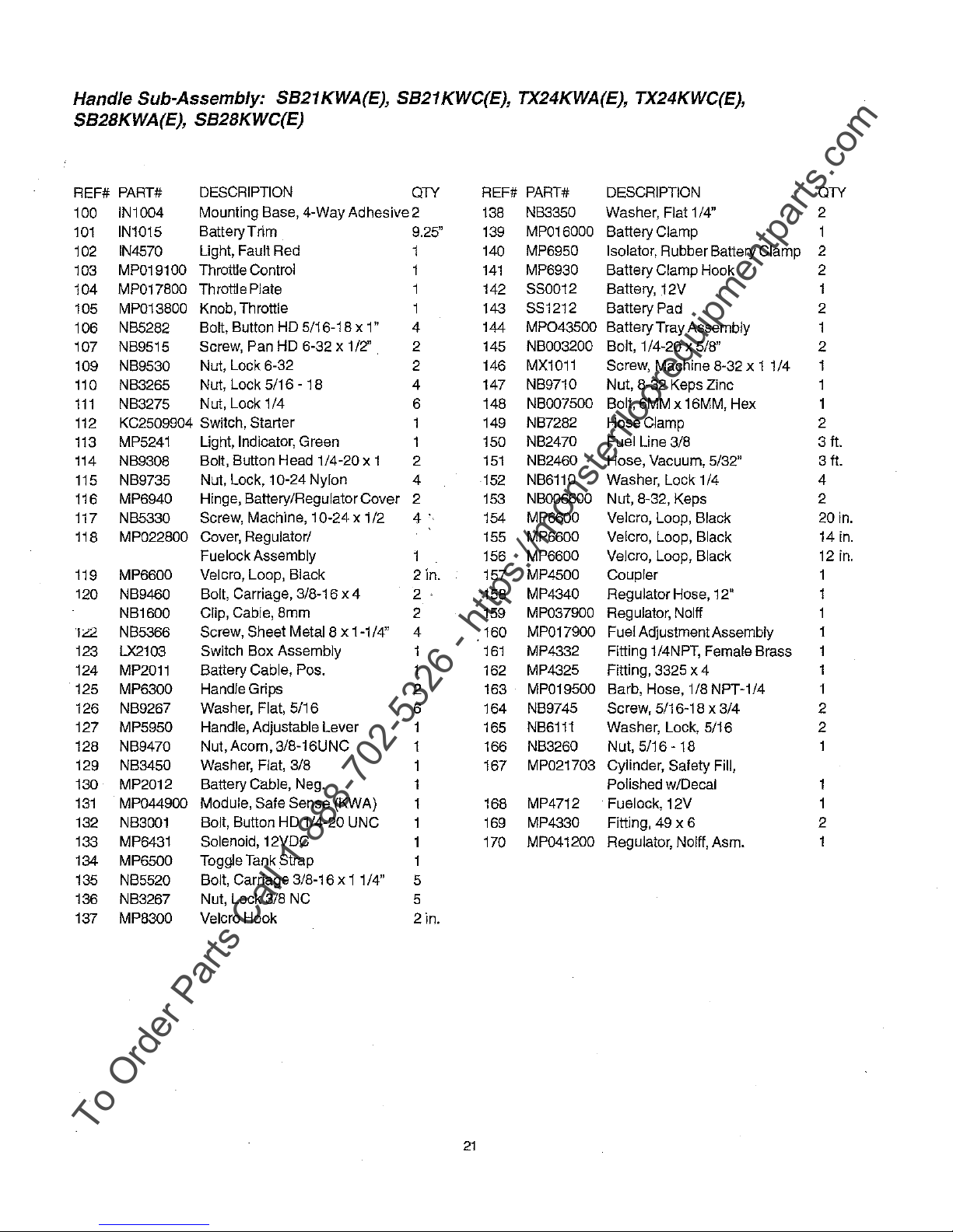
Handle Sub-Assembly:
To Order Parts Call 1-888-702-5326 - https://monsterfloorequipmentparts.com
5821
S82BKWA(E}, S828KWC(E)
KWA(E},
5821
KWC(E}, TX24KWA(E}, TX24KWC(E),
REF# PART#
100 IN1004
101
IN1015
IN4570 Light, Fault Red
102
MP019100 Throttle Control
103
MP017800 Throttle Plate 142
104
MP013800 Knob, Throttle 143
105
NB5282
106
107 NB9515
109 NB9530
110 NB3265 Nut, Lock 5/16 - 18 4 147
NB3275 Nut, Lock 1
111
KC2509904 Switch, Starter 149
112
MP5241 Light, Indicator, Green 150
113
114
NB9308
NB9735
115
116 MP6940
117 NB5330
118 MP022800
MP6600 Velcro, Loop, Black
119
120 NB9460 Bolt, Carriage, 3/8-16 x 4 2
NB1600
"1"2
NB5366
123 LX2103
124
MP2011
125 MP6300
NB9267 Washer, Flat, 5/16
126
127 MP5950
128 NB9470
129 NB3450 Washer, Flat, 3/8
MP2012 Battery Cable, Neg.
130
131
MP044900
132 NB3001
133 MP6431 Solenoid, 12VDC
134 MP6500 Toggle Tank Strap
135 NB5520
136 NB3267
137 MP8300 Velcro Hook
DESCRIPTION
Mounting Base, 4-Way Adhesive 2
Battery Trim
Bolt, Button HD 5/16-18 x 1"
Screw, Pan HD 6-32 x 1/2'' 2 145 NB003200 Bolt, 1 /4-20 x 5/8"
Nut, Lock 6-32
/4
Bolt, Button Head 1/4-20 x 1
Nut, Lock, 10-24 Nylon
Hinge, Battery/Regulator Cover
10-24
Screw, Machine,
Cover, Regulator/
Fuelock Assembly
Clip, Cable, 8mm
Screw, Sheet Metal 8 x 1-1/4"
Switch Box Assembly
Battery Cable, Pos.
Handle Grips
Handle, Adjustable Lever
Nut, Acorn, 3/8-16UNC
Module, Safe Sense (KWA)
Bolt, Button HD 1/4-20 UNC
Bolt, Carriage 3/8-16 x
Nut, Lock 3/8 NC
x 1/2
11/4"
QTY
9.25" 139
1
4
2 146
6 148
2
4
2
4·
2 in. 157
2 159
4 160
2 163
6 164 NB9745 Screw, 5/16-18 x 3/4
1 165
1 166 NB3260 Nut,
1 167
5
5
2in.
REF# PART# DESCRIPTION
138
140 MP6950 Isolator, Rubber Battery Clamp
141
144 MP043500
151
152
153
154 MP6600
155
156
'158
161
162
168
169
170
NB3350 Washer, Flat 1 /4"
MP016000
MP6930 Battery Clamp Hook
880012
881212
MX1011
NB9710
NB007500
NB7282
NB2470
NB2460
NB6110
NB006600 Nut, 8-32, Keps
MP6600
MP6600
MP4500 Coupler
MP4340 Regulator Hose, 12"
MP037900
MP017900
MP4332
MP4325 Fitting, 3325 x 4
MP019500 Barb, Hose, 1/8 NPT-1/4
NB6111
MP021703 Cylinder, Safety Fill,
MP4712 Fuelock, 12V
MP4330 Fitting, 49 x 6
MP041200
Battery Clamp
Battery, 12V
Battery Pad
Battery Tray Assembly
Screw, Machine 8-32 x 1 1
Nut, 8-32 Keps Zinc
Bolt, 6MM x 16MM, Hex
Hose Clamp
Fuel Line 3/8
Hose, Vacuum, 5/32"
Washer, Lock 1 /4
Velcro, Loop, Black
Velcro, Loop, Black
Velcro, Loop, Black
Regulator, Nolff
Fuel Adjustment Assembly
Fitting 1 /4NPT, Female Brass
Washer, Lock, 5/16
5/16-18
Polished w/Decal
Regulator, Nolff, Asm.
/4
QTY
2
1
2
2
2
2
1
2
3 ft.
3 ft.
4
2
20
14
12
1
1
1
1
2
2
2
in.
in.
in.
21

To Order Parts Call 1-888-702-5326 - https://monsterfloorequipmentparts.com

PAC~E~
To Order Parts Call 1-888-702-5326 - https://monsterfloorequipmentparts.com
Limited Warranty
Burnishers - Stripping Machines - Scrubbing Machines
To
qualify
for
this
Warranty:
1) Machine must be registered at the time of purchase on a form provided
Pioneer Eclipse Distributor is responsible for the registration of your machine. Please cooperate
Distributor
2) The machine must have been purchased from Pioneer
3) This warranty extends to the original purchaser only and is not transferable to subsequent owners.
TIME PERIODS
TWO (2) YEAR WARRANTY - For the following models: PE1700, Laser X, Magna 2000. Warranted to be free from
defects in material and workmanship for a period
owners. (See Exclusions.)
ONE
('1)
to be free from defects in material and workmanship
the original owners. (See Exclusions.)
in
supplying necessary information on the card.
of
two (2) years from the date
YEAR WARRANTY - For the following models SB,
Eclipse or an authorized Pioneer Eclipse Distributor.
SP,
ST,
for
a period of one
TX, XL,
by
Pioneer Eclipse® Corporation. Your
of
purchase
BA,
and the StarStrip 2400. Warranted
{'1)
year from the date of purchase by
with your
by
the original
L-'°
-,'N.....,.''-.
I
i....:::"""'
°]
EXCLUSIONS
'1)
Parts that fail through normal wear
body molding,
2) This warranty does not extend to parts affected by -misuse, neglect, abuse or improper maintenance.
defective parts must
3) Batteries warranted by battery manufacturer
4) Propane Engine warranted by engine manufacturer for 2 years (Note: The engine warranty period can
extended to a four (4) years
Contact your Pioneer Eclipse distributor for more information regarding this optional extended warranty
program.)
5) Valve train warraned
5) Electric motors warranted by motor manufacturer.
6) Deck Frame warranted
THE OBLIGATION OF PIONEER/ECLIPSE CORPORATION
1) The obligation of Pionee, Eclipse under this warranty is limited to repairing or replacing,
which
above.
2) Warranty repairs
3) Parts repaired or replaced under this warranty are warranted only during the balance of the original warranty
period.
WARRANTY SERVICE
To
obtain warranty service, take your machine and proof
Pioneer Eclipse
Eclipse Customer Service Department at 800 367 3550. If you are dissatisfied
or
write Pioneer Eclipse Customer Service Department for further assistance.
call
DISCLAIMER
PIONEER
MACHINE
APPLICABLE
OTHERWISE
...._
THE
1
COMPANY.
~
(Not
Covered
skirting, squeegees or other consumable parts).
is
proven to
All defective parts replaced ·under these warranties become the property
ECLIPSE
OR
ANY
TO
WARRANTY
be
will
will not reimburse expenses for service calls
OF
CONSEQUENTIAL
DISCLAIMS
OTHER
EACH
MACHINE.
by
Warranty)
by
reason
of
their characteristics (cords, pads, brushes, belts, bumpers,
be
returned
by
by
defective ln material or workmanship under normal use for the applicable period stated
be
made by your Pioneer Eclipse Distributor without charge for parts and labor.
INCIDENTAL
ANY
to
the
Dlstri_butor
on
Kawasaki engines providing the customer uses only approved Kawasaki oil.
Pioneer Eclipse for (1) year.
Pioneer Eclipse for (5) years.
ANY
RESPONSIBILITY
OR
CONSEQUENTIAL
EXCEPT
MACHINE
AS
AND
Copyright 2000 Pioneer Eclipse Corporation
for
('1)
FOR
STATED
NO
WARRANTY,
for ~credit.
year.
of
purchase to any authorized Pioneer Eclipse Distributor.
or
travel. For the Distributor
LOSS
OF
USER
TIME
EXCEPT
WARRANTIES,
IMPLIED
IN
DAMAGE
SUCH
EXPRESS,
at
its option, any part
of-
Pioneer Eclipse.
in
with the service that you receive,
OF
THE
AS
THE
your area, call Pioneer
PIONEER
STATED
COMPANY
OR
STATUTORY
IN
THE
DOES
ECLIPSE
WARRANTY
NOT
IS
~~
All
be
MADE
BY
.ll
~
,-
I
.L..-:.....,~::::~
ifLh (
_
~r
1
\\ 11"
~

Article#
To Order Parts Call 1-888-702-5326 - https://monsterfloorequipmentparts.com
Serial#
DOM:
Place Built: NC. USA
PIONEER ECLIPSE® CORPORATION
ECLIPSE ROAD. SPARTA. NC 28675
PHONE: 1-336-372-8080 OR 1-800-367-3550
______
_
© 2000 Pioneer Eclipse® Corporation
Machine Directive 98/37/EC as amended
Directive 91/368/EEC. Directive 93/44/EEC. and
CE
Certification applies
as indicated
only
to
machines
by
KWAE extension on
by
Directive 89/392/EEC.
by
Directive 93/68/EEC.
for
export
part
with
SafeSense
number.
LT014500-F
4/6/00
 Loading...