


Operator’s Manual
Failure to read and understand this manual before
operating this machine or performing service on this
machine may result in injury to the operator or nearby
personnel or result in damage to the machine or
nearby property. Each operator must be trained in the
operation of this machine before being allowed to use
it. Contact Amano Pioneer Eclipse Customer Service
at 1-800-367-3550 or 1-336-372-8080 or an authorized
Amano Pioneer Eclipse Distributor to inquire about
training or to request a replacement manual.
La falta de leer y de entender este manual antes de
usar esta máquina o de realizar servicio en esta
máquina puede dar lugar a lesión al operador o al
personal próximo o a resultado en daño a la máquina
o propiedad próxima. Cada operador debe ser
entrenado en la operación de esta máquina antes de
ser permitido utilizarla. Ponerse en contacto con el
servicio de Amano Pioneer Eclipse 1-800-367-3550 o
1-336-372-8080 o un distribuidor autorizado por
Amano Pioneer Eclipse para investigar sobre el
entrenamiento o para solicitar un manual.
Manquer de lire et de comprendre ce manuel
d'utilisation avant l'utilisation de cette machine ou
avant faire de maintenance sur la machine peut être
résulter en blessure à l'opérateur ou au personnel
proche ou peut endommagé la machine ou la propriété
proche. Chaque utilisateur doit être entraîné dans
l'opération de cette polisseuse avant l'utilisation.
Veuillez contacter le service àpres-vente de Amano
Pioneer Eclipse à 1-800-367-3550 ou 1-336-372-8080
et/ou un distributeur de Amano Pioneer Eclipse pour
vous renseigner concernant l'entraînement ou pour
obtenir un autre manuel d'utilisation.
UHS Battery Burnisher


FOR YOUR SAFETY
Do not store or use gasoline or other flammable vapors and liquids in the vicinity of this or
any other appliance.
Record This Important Information
Date of Purchase
Purchased From
Address
City State Zip
Phone Contact
Machine Model
Machine Serial Number
Important Phone Numbers
Medical Emergency
Police
Fire Department
In this Operation Manual you will find three statements that you must read and observe to ensure
safe operation of this machine.
DANGER! indicates that the possibility of severe bodily injury or death can occur if DANGER!
statements are ignored. Read and observe all DANGER! statements included in the Operation
Manual and attached to the machine.
WARNING! indicated that the possibility of bodily injury to the operator and other people can occur
if WARNING! statements are ignored. Read and observe all WARNING! statements included in
the Operation Manual and attached to the machine.
CAUTION! indicates that the possibility of damage to the machine or other property can occur if
CAUTION! statements are ignored. Read and observe all CAUTION! statements included in the
Operation Manual and attached to the machine.

1
Contents
Machine Specifications.......................................................2
Safety Precautions..............................................................3
Operator Responsibility..........................................4
Operator-Ear Sound Pressure Level.....................4
Hand-Arm Vibration...............................................4
Machine Preparation...........................................................5
Unpacking the Machine.........................................5
Connecting the Batteries.......................................5
Installing Steel Skirt...............................................5
Machine Operation.............................................................6
Controls and Instruments......................................6
Drive Controls........................................................7
Master On/Off Switch............................................7
Multi-Function Display...........................................7
Pad Pressure Gauge.............................................7
E-Stop Switch........................................................8
Raise/Lower Switch...............................................8
Burnish On/Off Switch...........................................8
Pad Pressure Adjustment Lever............................8
Fuses.....................................................................8
Onboard Battery Charger......................................9
How The Machine Works....................................10
Pre-Operation Check List....................................10
Turning on the Machine.......................................10
Changing Direction..............................................10
Stopping and Turning Off Machine......................10
Installing/Changing Burnishing Pad.....................10
Dust Box Removal...............................................11
Brake Release.....................................................11
Storage.................................................................11
Operation on Inclines...........................................11
Post-Operation Check List...................................11
Lubrication of Rear Casters.................................11
Body Maintenance............................................11
Plastic Cover Removal........................................12
Battery Maintenance............................................12
Static Drag Chain.................................................12
Repacking the Machine........................................12
Transporting the Machine....................................12
Maintenance.....................................................................13
Maintenance Chart..............................................13
Machine Troubleshooting.....................................14
Zapi PM4Q Alarm Codes............................15 & 16
Exploded Views and Parts Lists
Motion Controls...........................................17 & 18
Motor Cover/Dash Panels...........................19 & 20
Battery Cover..............................................21 & 22
Deck and Skirt.............................................23 & 24
Shroud Assembly.........................................25 & 26
Frame Assembly............................................27 - 32
Frame Assembly Manual Lif t........................33 & 34
Wiring Schematic..............................................................35
Wiring Schematic Manual Lift............................................36
Warranty............................................................................37

Machine Specifications - PowerGlide Express
VOLTAGE: ..........36 VOLT (3 - 12 VOLT BATTERIES)
BATTERIES:............................12 VOLT DEKA 228 AH
BURNISHING RATE:.(28in)±23,000 ft
2
/hr (2137 m2/hr)
(24in)±20,000 ft2/hr (1858 m2/hr)
BURNISH WIDTH:....................................28 in (71 cm)
24 in (61 cm)
BURNISH PAD:........................................28 in (71 cm)
24 in (61 cm)
PAD SPEED:................................................1500 RPM
PAD PRESSURE:...................................ADJUSTABLE
TRANSPORT SPEED:...............3.2 MPH (5.15 KmPH)
BURNISH SPEED:..........................2 MPH (3.2 KmPH)
BURNISH MOTOR:......................................PM 2.5 HP
TRANSAXLE (Sealed):..................400 WATT PM 26:1
BATTERY CHARGER:.................ON-BOARD 36v 25A
WHEELS:.................................................10 IN. SOLID
NOISE LEVEL:.................................................<70 dBA
VIBRATION LEVEL:........................Less than 2.5 m/s2
WEIGHT (W/O BATTERIES):................290 lb (132 kg)
WEIGHT (235 AH BATTERIES):...........950 lb (431 kg)
OVERLOAD PROTECTION:.............................FUSES
OPERATING TIME:.....................Approximately 2 HRS
LENGTH:................................................64 in (163 cm)
FRAME WIDTH:.......................................26 in (66 cm)
HEIGHT....................................................36 in (91 cm)
2

Safety Precautions
Anyone operating the machine should read the
following carefully and be informed of potentially
dangerous operating conditions. Operators should be
familiar with the location and use of all safety devices
on the machine. Do not use the machine if it is not in
proper operating condition, and report any damage or
operation faults immediately.
DANGER! This machine has parts including the
pad/brush assemblies that can cause severe injury if
these parts are contacted while they are moving. Do
not allow any part of the body or clothing to come in
contact with these parts while they are moving. Do not
try to change the pads/brushes while the machine is
running. Do not allow other people to come near the
machine while it is in operation. Do not allow the
machine to run unattended. Do not leave the machine
in a place where unauthorized or untrained personnel
could use the machine. Do not run the machine with
the pads/brushes off center, damaged or missing. Do
not operate the machine if the machine has loose parts.
WARNING! Batteries emit hydrogen gas. Explosion or
fire can result. Keep sparks and open flame away.
Keep covers open when charging. Do not smoke
around batteries. Avoid skin contact with the acid
contained in the batteries. Never allow metal objects
to lay across battery tops.
WARNING! Operate from the rear of the machine only.
WARNING! Inspect pad holders regularly. Afractured
pad holder may result in pad fragments causing injury.
WARNING! Use caution when operating the machine on
a ramp or incline. Do not turn the machine, or leave
it unattended, on a ramp or incline.
WARNING! Store machine inside. Keep the electrical
components of the machine dry. DO NOT PRESSURE
WASH MACHINE.
WARNING! Modifications or alterations to this machine
can lead to personal injury or damage to the machine.
Do not make unauthorized modifications or alterations
to this machine. Amano Pioneer Eclipse assumes no
liabilities for injury or damage resulting from an
unauthorized modification or alteration to the machine.
Any unauthorized modification or alteration to this
machine voids all warranties.
WARNING! The motor and motor controller become hot
enough while the machine is in operation, and for a
long time after the machine is shut off, to cause severe
burns. Do not touch these parts of the machine until
they have cooled.
WARNING! Injury can occur to the eyes and body while
using the machine. Safety goggles, safety shoes,
and safety clothing are recommended while operating
the machine.
WARNING! Machine vibration may cause tingling or
numbness in the fingers or hands. Gloves are
recommended to reduce machine vibration. If tingling
or numbness persists, shut off the machine. If the
vibration is caused by loose parts such as an off center
pad/brush, adjust or tighten these parts before using
the machine again.
WARNING! Do not burnish on an incline. This machine is
designed to burnish on a flat level floor.
CAUTION! Do not operate machine unless trained and
authorized. Do not operate machine unless you have
read and understand the operation manual. Do not
operate machine in flammable or explosive areas.
CAUTION! Before starting machine ensure all safety
devices are in place and functioning properly. Before
starting machine check for proper operation.
CAUTION! When using machine, go slowly on inclines or
slippery surfaces. Use care when operating machine in
reverse. Follow all manufacturers instructions on
chemical product containers when handling, mixing, or
using chemical products.
CAUTION! When servicing machine, stay clear of moving
parts. Do not wear loose clothing when working on
machine. Block machine wheels before raising or
jacking up machine. Use hoist stands that will support
the weight of the machine. Wear eye and ear
protection when using pressurized air. Disconnect
battery connections before servicing machine. Use
only replacement parts supplied by Amano Pioneer
Eclipse or a Amano Pioneer Eclipse Authorized
Distributor or Service Center.
3

This machine is manufactured for
commercial use only.
This machine is designed and manufactured for burnishing
indoor hard floor surfaces. Amano Pioneer Eclipse does
not recommend use of this machine in any environment
other than an indoor environment.
Battery powered floor equipment is designed and
manufactured for commercial use only. These machines
are designed to burnish most modern types of floors
including composition tile, stone, marble, terrazzo, and
resilient floor covering, and some coated wood floors.
Operator Responsibility
The operator is responsible for performing the
recommended daily maintenance and checkups of the
machine to keep it in good working condition. The
operator must inform the service mechanic or supervisor
when recommended maintenance procedures are required
as prescribed in the MAINTENANCE section of this
manual.
Read this manual carefully before operating this machine.
FOR SAFETY: Do not operate machine before reading
and understanding the operation manual.
Check the machine for shipping damage.
Keep your machine regularly maintained by following the
maintenance information in this manual. We recommend
taking advantage of a service contract from your Amano
Pioneer Eclipse Authorized Distributor or Service Center.
Order parts and supplies only from an Authorized Amano
Pioneer Eclipse Distributor. Use the parts illustration
section of your manual when ordering parts.
During and after operation, perform the recommended
daily and hourly procedures outlined in the Maintenance
Chart.
Test for Operator-Ear Sound Pressure
Level
Amano Pioneer Eclipse measures and rates the operatorear sound pressure level for hand-guided floor treatment
and floor cleaning machines for industrial use. All tests
are performed in accordance with European Machinery
Directive (98/37/EC).
Outdoor test area consists of a flat open space free
from effects of signboards, buildings or hillsides for at
least 15m (50ft) from the center of the test surface.
Indoor tests are conducted in a semi-anechoic or
sound deadening room.
The test surface is a single sheet of floor covering at
least 1m (3.3ft) wider and longer than the equipment
being tested. In order to not affect the sound reading,
the observer taking readings is at least 2m (6.6ft) from
the equipment being tested, or standing directly
behind the operator.
All machines are tested while stationary and centered
on the test surface. With the traction drive in neutral
(where applicable) the test is conducted with the
machine at maximum engine or motor speed as
specified by the manufacturer.
The operator is located in the normal operating
position with the microphone or meter supported
independent of the machine, 1, 68m (66in) above the
test surface, 25cm (10in) to the right and left
centerline of the operators position, and 20cm (8in) to
the rearmost point of the handle, with the handle in
the most forward position.
The sound level meter is observed for a minimum of 5
seconds or until a stabilized reading is obtain. The
maximum repeatable sound level observed during the
test at each microphone position is recorded and
documented.
Test for Hand-Arm Vibration at the
Grip Surface of Hand-Guided
Machinery
Amano Pioneer Eclipse measures and rates the vibration
at the machine-hand contact surface of hand-guided
machines that are provided with handles in accordance
with European Machinery Directive (98/37/EC).
The test area consists of a flat open floor area that
allows the machine to be operated normally
The transducer is mounted firmly at a point halfway
along the length of the handle where the handle would
normally be held.
Machines are tested while stationary, with all
mechanisms necessary for the equipment to perform
its intended functions engaged and the traction drive
in neutral (if applicable). The machine will be tested
at maximum engine or motor speed as specified by
the manufacturer of the subject machine.
The measurements are recorded from the dominant
axis.
4

Machine Preparation
Unpacking the Machine
1. Cut and remove black bands holding the box to the
pallet.
2. Remove staples attaching the box to the platform at
the edge of the box.
3. With two people, one at either end of the box, lift
box straight up and off the machine.
4. Remove loose accessories from the top of machine.
5. Cut and remove the band across the top of the
burnishing head.
6. Raise the battery cover by lifting on the front of the
cover and tilting it back to expose the battery
compartment. When the battery cover is opened all
the way it should rest on top of the handlebars.
7. Cut and remove the bands across the battery
compartment.
8. Close the battery cover.
9. Using a 7/16”
wrench, socket or
adjustable wrench,
remove the two lag
screws attaching
the wood block
located behind the
two drive wheels.
10. Release transaxle
brake by pulling the
black knob located
at the back of the
machine below the
plastic cover. (Ref.
“How the Machine
Works - Brake
Release”)
11. While pulling the machine backwards, by the
handlebars, ease it off of the pallet to prevent
damage.
Connecting the Batteries
The machine is shipped
without batteries installed.
1. Raise charger bracket.
2. Place the batteries in
the battery tray.
3. Connect the batteries together as shown on the
battery connection diagram.
4. DANGER! Incorrect connection of batteries can
cause explosion and/or serious injury. Double
check battery connections.
5. Lower the Charger Bracket
6. Connect the Anderson plugs together.
Installing Steel Skirt
1. Raise the deck of the machine up to the transport
position (Ref. Machine Operation - Raise/Lower
Switch)
2. Lift the deck upward about 90 degrees by pulling up
on the front of the deck. At this point, the tilt latch
will hold the deck in the pad change position. (Ref.
Machine Operation - Installing/Changing Burnishing
Pad)
3. Remove steel skirt from bubble wrap packing and
on the outside of the skirt, loosen the 1/4” hex bolt
with jam nut until it is free from the brass insert.
4. Gently wrap the skirt around the deck. Do not flex
the skirt more than needed, this could bend or
damage the skirt.
5. With the skirt around the deck, position the slotted
hole in the skirt onto the round stud on the bottom
rear edge of the deck.
6. Re-install 1/4” hex bolt into brass insert. Tighten bolt
until skirt is snug around the deck but also floats up
and down freely on the felt edging.
7. Tighten jam nut and lower deck to transport
position. (Ref. Machine Operation: Installing /
Changing Burnishing Pad)
5

Machine Operation
Controls and Instruments
Fuse
MDI
Deck Raise/Lower SW
Pad Pressure
Gauge
Key SW
Burnish On/Off SW
Accelerator
E-Stop
Pad Pressure
Adjust
6

Multiple Display Indicator, MDI
The multi-function display indicates number of hours the
machine has been operated. It also displays any alarm
code used for troubleshooting. There are four green LEDs
and one red led. The four green LEDs indicate state of
battery charge. If all four LEDs are lit the battery is
90-100% charged. If three LEDs are lit the battery is
60-80% charged. If two LEDs are lit the battery is 40-50%
charged. If only one LED is lit the battery is 20-30%
charged. Once the battery drops below 20% battery
charge the red LED will blink, the burnish pad will stop and
the traction speed will be reduced by 50%. The red LED
will also blink if there are any alarm codes displayed.
There are also two icons on the display. The turtle
hourglass icon represents the machine is in burnish mode
and the maximum speed is reduced. The hourglass icon
represents the machine is counting hours of operation.
Pad Pressure Gauge
The pad pressure gauge indicates the load on the burnish
motor. The light green area represents the normal
burnish operation. The dark green represents heavy
burnishing operation. If the machine is operated in the
orange area for an extended amount of time (>30 min.)
the machine will over heat and go into thermal cutback
(reduced speed and performance). If the machine is
operated in the red area for a sustained time (>5min.) the
power fuse will fail and the burnish pad will stop. The fuse
will have to be replaced.
Drive Controls
The accelerator moves in both directions, forward and
back. Twist the handle grip forward for forward speed
control and twist the handle grip back for reverse speed
control. The accelerator is variable speed therefore the
more you twist the handle grip, the faster the machine will
go.
Turning: Push the machine in the opposite direction of the
turn, holding the handle grips firmly.
Stop: Release the accelerator handle. The machine will
automatically brake to a stop.
Master On/Off Switch
The PowerGlide Express features a master key switch.
On: Turn the key all the way to the right.
Off: Turn the key to the left or OFF position.
7

Pad Pressure Adjustment Lever
The pad pressure adjustment
lever adjusts the amount of
down pressure exerted on the
burnish shroud. The pad
pressure lever has 3 positions
(light, medium, heavy).
NOTE: When using a new pad
or when buffing freshly applied wax, the light setting
should be used. As the pad breaks in and/or the wax
starts to harden, the pad pressure lever can be adjusted to
keep the pad pressure gauge in the green operational
area. If the pad pressure adjustment lever is in the heavy
position and the pad pressure gauge is in the white area,
this indicates the burnish pad either needs to be changed
or has become clogged with dirt and wax.
Fuses
The PowerGlide Express has 2 power fuses and 2 logic
fuses. One power fuse is ANL 100 amp, which protects
the burnish motor. The other power fuse is ANL50 amp,
which protects the traction motor and controller. The two
logic fuses are located on the dash panel. Both are rated
at 3 amps. One protects the actuator and the other
protects the logic circuit of the machine.
Logic Fuses
Power Fuses
E-Stop Switch
The emergency stop switch is provided for added safety.
Press the RED knob to stop all function of the burnisher
and come to an immediate stop. To reset the emergency
stop switch pull up on the red knob.
Raise/Lower Switch
The Raise/Lower switch controls the position of the
burnish shroud.
Lower Shroud for burnish mode: Press the bottom of the
switch. The shroud will lower to the burnishing position.
Raise Shroud for transport/Pad Change mode: Press the
bottom of the switch. The shroud will raise to the
transport/Pad Change position.
Burnish On/Off Switch
The burnish On/Off switch controls the burnish pad motor.
Turn the burnish pad on and start burnishing: Press the
top of the switch. The green light is ON.
Turn the burnish pad off and stop burnishing: Press the
bottom of the switch. The green light is OFF.
NOTE: The burnish pad will not begin to turn until the
accelerator is engaged by pushing or pulling the
accelerator handle. When the accelerator is released the
pad will stop turning within 5 seconds.
8

Onboard Battery Charger
To charge the batteries, first drive the machine to a flat,
dry, well-ventilated area then turn the machine off. Check
the water level in all the battery
cells. If the level is low, add
just enough distilled water to
cover the plates.
DO NOT OVERFILL.
Then plug the female end of
the supplied charging cord into
the inlet mounted on the left
side of the machine. Then
plug the male end into a 115VAC 50/60Hz (+/-10%) wall
socket. The battery charger will initialize and then soft
start the charging cycle.
WARNING! Batteries emit hydrogen gas when
charging. Explosion or fire can result. Keep sparks
and open flame away when charging.
CAUTION! When servicing machine, wear protective
gloves and goggles when handling batteries or battery
Battery Charger Controls:
1. Three-digit display + symbol (1), to view A=charging
current, U=battery voltage, h=charging time,
C=charging ampere-hours (AH), E=energy used
to charge (KWh)
2. Button for the Selection of the display mode (2): A, U,
h, C, E. After 10 seconds the display returns to
the display of charging current.
3. Red control indicator (3): when it is on, the charging
cycle has started.
4. Yellow control indicator (4): when it is on, the final
phase of the charging cycle has started.
5. Green control indicator (5): when it is on, the charging
cycle has finished.
Once the charge cycle is complete, the charger will
remain active in a trickle charge mode to maintain the
charge on the batteries until the charger is unplugged
from the wall socket.
9

How the Machine Works
The Burnish components of the machine are:
Burnish pad holder
Burnish pad
Burnish motor
Dust Collection Box
As the machine moves forward, the burnish pad shines
the floor. Any excess dirt or wax gets picked up by the
pad and distributed into the dust collection box via the
dust collection system.
Pre-Operation Checklist
Before operating the machine:
Check that the Burnish Switch is in the off position.
Check the pad holder to ensure there are no breaks
or cracks.
Check correct connection of the batteries.
Check that the Dust Collection Box is empty and
latched into position.
Check that the E-stop is pulled up in the operating
position.
Turning on the Machine
1. Complete pre-operation check.
2. Turn the Key to the ON position.
3. Lower the shroud to the burnish mode position.
4. Turn on the burnish switch and push or pull the
handle in the forward/reverse direction.
5. Adjust pad pressure lever as needed.
Changing Direction
The direction the machine is traveling can be changed by
pushing or pulling the accelerator in the opposite direction.
The direction can be changed while the machine is in
motion or stationary. If the machine is in motion and the
direction is switched, the vehicle will slow down and
change direction.
Stopping and Turning Off Machine
To stop the machine, release the accelerator and the
machine will smoothly break to a stop and after 3 seconds
the burnish motor will stop. When turning the machine off,
turn off the burnish switch and then turn off the key switch.
In an emergency situation the E-Stop can be used to
immediately stop the vehicle and stop the burnish motor.
Installing/Changing Burnishing Pad
1. Make sure the
Burnish Switch is
OFF.
2. Raise the shroud to
the transport/pad
change position. Lift
on the front of the shroud and
tilt shroud into the pad change
position.
3. Remove the center device
by turning counterclockwise
and carefully remove the old
pad from the Velcro material.
CAUTION! CAREFULLY INSPECT THE PAD HOLDER
FOR CRACKS OR DAMAGE! REPLACE IF NECESSARY.
4. Pull center from new pad, align pad on pad holder
and secure with centering device by turning
clockwise.
5. Press pad firmly onto
Velcro.
6. Lift the front of the shroud
and lift the shroud release
lever and SLOWLY let the
shroud return to the down
position.
CAUTION! KEEP HOLD OF THE DECK TO AVOID
INJURY!
10

Dust Box Removal
Monitor the dust box carefully and empty as needed. The
dust collection system will not operate effectively when the
dust box is full. Under heavy burnishing conditions the
dust box should be emptied every hour.
1. Turn off the Burnish Motor.
2. Unlatch the latches from the
dust box.
3. Pull the dust box out of the
motor cover.
4. Remove filter cover and
filter.
5. Pour dust and debris from
the dust box into a waste
container.
6. If necessary blow the dirt
out of the air filter.
Brake Release
Pull the brake release lever out to
release the brake in order to move
the burnisher without power. To
reset the brake push the lever in
toward the frame.
FOR YOUR SAFETY: THE
BRAKE SHOULD ALWAYS BE
ENGAGED WHILE THE
BURNISHER IS IN USE!
Storage
1. Machine should be stored in a dry environment.
2. Store machine away from objects that may fall and
damage it.
3. Never store burnisher near an open flame or heat
producing device.
4. Make sure burnisher is cleaned properly by wiping
machine down with damp cloth before storing.
CAUTION! NEVER PRESSURE WASH MACHINE!
5. Disconnect batteries before storage.
Operation on Inclines
CAUTION! When using the machine, go slowly on
inclines.
CAUTION! Do not run burnish pad on an incline.
The maximum rated climb and descent incline is 10°.
Post Operation Checklist
Turn the machine OFF and perform the following checks:
Check for wire, string, or twine wrapped around the
burnish pad
Check Wire fray or damage
Empty the Dust Collection Box
Inspect batteries
Plug in on-board battery charger.
Lubrication of Rear Casters
Each of the two rear caster
has one grease fitting on the
caster swivel. Lubricate each
caster with a grease gun
every 100 hours of machine
operation.
Body Maintenance
The body may be cleaned with a damp cloth to remove
dust and scuff marks. More stubborn scuff marks on the
tank exterior can be removed with a vinyl cleaner.
11

Plastic Cover Removal
The back panel has one
screw knob in the center of
the back cover. Remove the
screw knob and pull the
cover toward you from the
top. The back cover will
come off and expose the
electronics of the machine.
The motor cover is attached to the
shroud with (4) 5/16-18 hex head
bolts. Using a 1/2 inch wrench,
remove the bolts and remove the
motor cover.
The Battery Cover is hinged at the
dash for easy battery
maintenance. Lift the bottom of
the battery cover, at the shroud,
up and swing the cover. Place
the hood support rod into the hole
on the battery connection bracket
to hold the hood up.
FOR YOUR SAFETY: NEVER OPERATE BURNISHER
WITHOUT ALL COVERS IN PLACE!
Battery Maintenance
The batteries are deep cycle 12 volt batteries. The
lifetime of the batteries is limited by the number of charges
the batteries receive. To get the most life from the
batteries, charge them when the battery discharge LED
(Red) starts to blink (20% charge left). Use only the
on-board battery charger supplied to charge the batteries.
Periodically clean the top surface of the batteries and the
terminals, and check for loose connections. Use a strong
solution of baking soda and water. Brush the solution
sparingly over the battery tops, terminals, and cable
clamps. DO NOT ALLOW ANY BAKING SODA
SOLUTION TO ENTER THE BATTERIES! Use a wire
brush to clean the terminal posts and cable connectors.
After cleaning, apply a coating of clear battery post
protectant to the terminals and the cable connectors.
Keep the tops of the batteries clean and dry.
To prevent a possible short circuit, keep all metallic objects
off the top of the batteries. Replace any worn or damaged
wires.
Never add acid to the batteries, only distilled water.
Always keep the battery caps on, except when adding
water or taking hydrometer readings.
Check the electrolyte level in each battery cell before and
after charging, and after every 50 hours of operation. Do
not charge the batteries
unless the fluid is slightly
above the battery plates. If
needed, add just enough
distilled water to cover the
plates. Never add acid to
the batteries. Do not
overfill.
Measuring the specific gravity, using a hydrometer, is a
way to determine the charge level and condition of the
batteries. If one or more of the battery cells test lower
than the other battery cell (0.050 or more), the cell is
damaged, shorted, or is about to fail.
Static Drag Chain
A static drag chain prevents the buildup of static electricity
in the machine. The chain is attached to the frame.
Make sure the chain is
always touching the
floor.
Repacking the Machine
Refer to Unpacking section on page 5 and repack
machine using original packing materials and container.
Transporting the Machine
When shipping the machine, make sure the batteries are
disconnected and the machine is secured in the
transporting vehicle with the brake set.
12

Maintenance
*These items must be performed with the proper tools and training. Contact a Amano Pioneer Eclipse Factory
Certified Technician unless you have the proper equipment and mechanical proficiency.
13

Machine Troubleshooting
14
No traction signal

Alarm Codes ZAPI PM4Q
*Given the following alarm codes, troubleshooting should only be done by Amano Pioneer Eclipse Factory Certified
Technician. A programming handset may be required for troubleshooting.
15

Alarm Codes ZAPI PM4Q (continued)
16

POWERGLIDE EXPRESS MOTION CONTROLS
081508
RF008000
17

Ref.Part # Description Qty.
1 NB9745 SCREW, CAP, 5/16-18 X 3/4 4
2 NB9445 WASHER, STAR LOCK, #10 2
3 NB9302 SCREW, SET, 1/4-20 X 3/8, KNURL 3
4 NB6111 WASHER, LOCK, 5/16 6
5 MX1025 SCREW, PAN HD, 10-24 X 3/4 2
6 NB3260 NUT, 5/16-18, NC 7
7 NB054000 ROD, THREADED, 10-32 X 1.5” LONG 1
8 NB048300 WASHER, FLAT, #4 4
9 NB048200 SCREW, PAN HD, #4-40 X 1 1/2,
PHILLIPS 2
10 NB027600 NUT, #10-24, SS 2
11 NB007000 NUT, LOCK, NYLON, 4-40 2
12 NB006600 NUT, KEPS, 10-32 1
13 NB005200 SCREW, SET, 10-24 X 5/16, NYLON
TIP 1
14 MP275800 SPRING, TORSION, WIG-WAG 1
15 MP112500 ARM, LINKAGE, POTENTIOMETER 1
16 MP223300 SPACER, HANDLE, PLATE, WIG-WAG 1
18 MP112100 BRACKET, HANDLE, RIGHT, ASM. 1
19 MP111900 BRACKET, HANDLE, WIG-WAG,
LEFT, ASM. 1
20 MP113300 WINDER, SPRING, WELDMENT 1
21 MP275500 TUBE, OUTER, WELDMENT 1
22 MP111701 PLATE, MOUNTING, CONTROLLER,
MOTION 1
23 MP151100 ROD END, FEMALE, 10-24 2
24 MP113001 CAM, SWITCH, ADJUSTABLE,
PAINTED 2
26 PG013500 WIRING HARNESS,
POTENTIOMETER, PGX 1
27 MP113501 PLATE, SPACER, MICROSWITCH,
PAINTED 1
28 MP276100 SPACER, ARM, POTENTIOMETER 1
29 NB9645 WASHER, FLAT, #10 1
POWERGLIDE EXPRESS MOTION
CONTROLS
18
081508

POWERGLIDE EXPRESS MOTOR COVER/DASH PANELS
02/06/07
RF008100
19

Ref.Part # Description Qty.
1 PG005001 GRILL, MOTOR COVER,
POWERGLIDE, PAINTED 1
2 MP237300 LATCH, DRAW, 4.16, W/REV.
KEEPER 2
3 NB007400 BOLT, PHILLIPS PAN HD, #8-32 X 1/2 3
4 NB9710 NUT, KEPS, 8-32, ZINC 4
5 NB043600 SCREW, PAN HD, HI-LO, #8 X 3/8” 5
PANEL, DASH, LEFT POWERGLIDE
EXPRESS
1 PG010501 PANEL, DASH, LEFT, PGX, PAINTED1
2 PG012300 DECAL, DASH, POWERGLIDE
EXPRESS, LEFT 1
3 MP233900 DISPLAY, MULTI-FUNCTION 1
4 MP209700 SWITCH, ROCKER, 36V, DPST 1
5 MP234700 FUSE, GLASS, 3 AMP 2
6 MP234600 FUSEHOLDER, HTB-261 2
MOTOR COVER, POWERGLIDE EXPRESS
20
120807
PANEL, DASH, RIGHT, POWERGLIDE
EXPRESS
1 PG010401 PANEL, DASH, RIGHT, PGX,
PAINTED 1
2 PG012400 DECAL, DASH, POWERGLIDE
EXPRESS, RIGHT 1
3 MP236900 AMMETER, 0-150 AMPS 1
4 MP209800 SWITCH, ROCKER, 36V, SPST.
W/GREEN LIGHT 1
5 MP206700 SWITCH, KEY, 2 POSITION 1
PANEL, DASH, LEFT, POWERGLIDE
EXPRESS, MANUAL LIFT
1 PG010501 PANEL, DASH, LEFT, PGX, PAINTED1
2 PG012300 DECAL, DASH, POWERGLIDE
EXPRESS, LEFT 1
3 MP233900 DISPLAY, MULTI-FUNCTION 1
4 MP230200 PLUG, HOLE, CONTURA, BLACK 1
5 MP234700 FUSE, GLASS, 3 AMP 2
6 MP234600 FUSEHOLDER, HTB-261 2
7 NB005700 NUT, 5/26-24, JAM 1
8 NB031700 PLUG, HOLE, 5/16 X 23/32 HEAD 1
120807

POWERGLIDE EXPRESS BATTERY COVER
081508RF007500
21

BATTERY COVER
Ref.Part # Description Qty.
1 MP101800 HINGE, LH 1
2 PG008900 COVER, BATTERY, PGX, TRIMMED 1
3 PG012500 DECAL, BATTERY, POWERGLIDE
EXPRESS 1
4 PG010001 GRILL, COVER, BATTERY, PGX 1
5 NB6545 SCREW, CAP, HH, 5/16-18 x 1 4
6 MX1045 NUT, HEX, 1/4-20 2
7 NB6110 WASHER, LOCK, 1/4 2
8 PG010101 BRACKET, RETAINER, COVER, PGX,
FORMED 2
9 MP077400 COVER, TENSION, SPRING 2
10 NB6535 SCREW, CAP, HH, 1/4-20 X 3/4 2
11 MP101900 HINGE, RH 1
Ref.Part # Description Qty.
12 NB9267 WASHER, FLAT, 5/16 4
13 NB6111 WASHER, LOCK, 5/16 4
14 NB3260 NUT, 5/16-18, NC 4
18 NB043600 SCREW, PAN HD, HI-LO, #8 x 3/8” 15
081508
22

POWERGLIDE DECK AND SKIRT
23

28” PADHOLDER ASSEMBLY
24
24” PADHOLDER ASSEMBLY
Ref.Part # Description Qty.
1 MP236600 PADHOLDER, 28” POWERGLIDE
COMPLETE 1
1.1 MP196300 RING, RELIEF, STRESS, LARGE,
PADHOLDER 1
1.2 NB3275 NUT, LOCK, 1/4 6
1.3 SA004000 PADHOLDER, 28”, W/STUDS ONLY 1
1.4 MP8310 VELCRO, HOOK, STUDS 68
1.5 MP257900 FLEXI-DISC, W/O LIP, .75” BORE
W/ INSERT 1
1.6 MP066300 RING, SPACER, CENTER LOK II 1
1.7 MP012700 RETAINER, PAD, CENTER-LOK II
(SCREW-IN) 1
1.8 PD006028 PAD, 28” BLUE BLEND-RND 1
1.9 NB3350 WASHER, FLAT, 1/4 6
1.10 NB9319 SCREW, BH, 1/4-20 X 1 1/4” 6
1.11 NB032500 INSERT, 3/8-16, STAFAST 1
1.12 MP297201 PLATE, SPACE, PADHOLDER 1
28” DECK ASSEMBLY
2 PG006300 SHROUD, 28”, POWERGLIDE,
ASM. 1
2.1 PG005900 SHROUD, 28” , POWERGLIDE 1
2.2 MP007300 DECAL, KEEP HANDS/FEET 1
2.3 MP139900 BUSHING, SKIRT, STEEL 1
2.4 NB038800 SCREW, SOCKET HD,
1/4-20 x 1 1/4 LOCTITE 1
2.5 MP8300 VELCRO, HOOK, 1” W/ADHESIVE,
25 YDS/ROLL 2.78 YDS.
2.6 NB3275 NUT, LOCK, 1/4 1
2.7 PG000500 TUBE, DUST, POWERGLIDE 1
2.8 RV013200 SCOOP, 28” 1
2.9 NB3350 WASHER, FLAT, 1/4 7
2.10 NB3001 SCREW, BH, 1/4-20 X 3/4 5
2.11 MP139600 FELT, POLYESTER, 28 OZ,
BLK 8.33 FT.
2.12 NB038700 RIVET, 3/16 X 1/2 X 3/8HD 9
28” SKIRT ASSEMBLY
3 PG006200 SKIRT, STEEL, POWERGLIDE, 28”
ASM. 1
3.1 MX1045 NUT, HEX, 1/4-20 1
3.2 NB3350 WASHER, FLAT, 1/4 2
3.3 NB050600 BOLT, HEX, TAP, 1/4-20 X 2 1/2” 1
3.4 PG006100 SKIRT, STEEL, 28”, POWERGLIDE,
PAINTED 1
3.5 MP209500 EDGING, BOTTOM, SKIRT 8.33 FT.
3.6 MP221900 EDGING, WEAR, FELT, 1/4 X 7/8 1
3.7 NB043900 RIVET, 3/16 X 1/2 X 5/8 HD, BLACK 5
3.8 NB044000 WASHER, FLAT, #10, BLACK 5
3.9 MP139700 MOLDING, BUMPER, SKIRT,
STEEL 8.33 FT.
3.10 NB6501 INSERT, 1/4-20, COMPRESSION
TYPE 1
Ref.Part # Description Qty.
1 MP264400 PADHOLDER, 24” POWERGLIDE,
COMPLETE 1
1.1 MP196300 RING, RELIEF, STRESS, LARGE,
PADHOLDER 1
1.2 NB3275 NUT, LOCK, 1/4 6
1.3 SA007800 PADHOLDER, 24”, W/STUDS ONLY 1
1.4 MP8310 VELCRO, HOOK, STUDS 76
1.5 MP211500 FLEXI-DISC, W/O LIP, .75” BORE 1
1.6 MP066300 RING, SPACER, CENTER LOK II 1
1.7 MP012700 RETAINER, PAD, CENTER-LOK II
(SCREW-IN) 1
1.8 PD006024 PAD, 24” BLUE BLEND-RND 1
1.9 NB3350 WASHER, FLAT, 1/4 6
1.10 NB9319 SCREW, BH, 1/4-20 X 1 1/4” 6
1.11 NB032500 INSERT, 3/8-16, STAFAST 1
1.12 MP297201 PLATE, SPACE, PADHOLDER 1
24” DECK ASSEMBLY
2 PG007500 DECK, POWERGLIDE, 24” ASM. 1
2.1 PG007600 SHROUD, POWERGLIDE, 24” 1
2.2 MP007300 DECAL, KEEP HANDS/FEET 1
2.3 MP139900 BUSHING, SKIRT, STEEL 1
2.4 NB038800 SCREW, SOCKET HD,
1/4-20 x 1 1/4 LOCTITE 1
2.5 MP8300 VELCRO, HOOK, 1” W/ADHESIVE,
25YDS/ROLL 2.5 YDS.
2.6 NB3275 NUT, LOCK, 1/4 1
2.7 PG000500 TUBE, DUST, POWERGLIDE 1
2.8 RV013200 SCOOP, 24” 1
2.9 NB3350 WASHER, FLAT, 1/4 7
2.10 NB3001 SCREW, BH, 1/4-20 X 3/4 5
2.11 MP139600 FELT, POLYESTER, 28 OZ,
BLK 7.5 FT.
2.12 NB038700 RIVET, 3/16 X 1/2 X 3/8HD 9
24” SKIRT ASSEMBLY
3 PG007400 SKIRT, STEEL, POWERGLIDE, 24”
ASM. 1
3.1 MX1045 NUT, HEX, 1/4-20 1
3.2 NB3350 WASHER, FLAT, 1/4 2
3.3 NB050600 BOLT, HEX, TAP, 1/4-20 X 2 1/2” 1
3.4 PG007300 SKIRT, STEEL, 24”, POWERGLIDE,
PAINTED 1
3.5 MP209500 EDGING, BOTTOM, SKIRT 7.5 FT.
3.6 MP221900 EDGING, WEAR, FELT, 1/4 X 7/8 1
3.7 NB043900 RIVET, 3/16 X 1/2 X 5/8 HD, BLACK 5
3.8 NB044000 WASHER, FLAT, #10, BLACK 5
3.9 MP139700 MOLDING, BUMPER, SKIRT,
STEEL 7 FT.
3.10 NB6501 INSERT, 1/4-20, COMPRESSION
TYPE 1
08/30/07

POWERGLIDE EXPRESS SHROUD ASSEMBLY
25
010209

Ref.Part # Description Qty.
1 PG005600 LATCH, TILT, WELDMENT 1
2 PG007400 SKIRT, STEEL, POWERGLIDE,
24”, ASM. 1
PG006200 SKIRT, STEEL, POWERGLIDE,
28”, ASM. 1
3 MP264400 PADHOLDER, 24”, POWERGLIDE,
COMPLETE 1
MP236600 PADHOLDER, 28”, POWERGLIDE,
COMPLETE 1
4 MP220700 WASHER, LATCH, TILT, NYLON 3
5 NB018000 WASHER, FLAT, NYLON, 1/2” 2
6 NB6042 SCREW, CAP, 3/8 X 1 8
7 NB048500 PIN, CLEVIS, 1/2 X 1 3/4 2
8 LX2105 CLIP, HITCH PIN, STRAIN RELIEF 2
9 PG006700 COVER, FILTER, POWERGLIDE,
ASM. 1
10 PG000400 CONTAINER, DUST, POWERGLIDE 1
11 MP220400 FILTER, DUST, POWERGLIDE 1
12 MP220800 SEAL, DUSTBOX, POWERGLIDE 1
13 NB6545 SCREW, CAP, HH, 5/16-18 X 1 4
14 NB011600 INSERT, 5/16-18, COMPRESSION
TYPE 4
15 MP140000 FELT, DOT 1
16 NB8175 PIN, PRESTO, 3/32 X 1 5/8 2
17 MP220600 SPACER, LATCH, TILT, NYLON 1
18 MP220500 SPACER, LATCH, TILT 1
19 MP208100 CAPLUG, VINYL, .485 I.D., 2.5L 1
20 NB9550 SCREW, CAP, HH, 1/4-20 X 2 1/4 1
21 PG015600 ARM, LIFT, POWERGLIDE, ASM. 2
22 MP240700 PLATE, PIVOT, MOUNT, LIFT, LEFT,
ASM. 1
23 MP240800 PLATE, PIVOT, MOUNT, LIFT, RIGHT,
ASM. 1
24 PG000900 BRACE, CROSS, FRONT, WELD. 1
SHROUD ASSEMBLY
26
010208
Ref.Part # Description Qty.
25 PG005200 PLATE, MOTOR, POWERGLIDE,
WELDMENT 1
26 PG014000 COVER, MOTOR, PGX24 ASM. 1
PG014100 COVER, MOTOR, PGX28 ASM. 1
27 NB9460 BOLT, CARRIAGE, 3/8-16 X 4, ZINC 1
28 NB046200 NUT, HEX, 3/8-16, GD5 1
29 NB9680 SCREW, BH, 1/4-20 X 1 1/2 1
30 NB054500 SCREW, SOCKET, 3/8-16 5/8, FLAT,
CS 4
31 MP236700 KEY, 3/16 X 7/8 1
32 MP278600 MOTOR, 2.5 HP, PM, BRUSHED,
1500RPM 1
33 NB6044 SCREW, CAP, 3/8-16 X 1 1/4 4
34 NB3450 WASHER, FLAT, 3/8 8
35 MX1075 WASHER, LOCK, 3/8 12
36 NB3267 NUT, LOCK, 3/8 NC 4
37 MX1080 WASHER, FLAT, 3/8 9
38 NB6100 WASHER, LOCK, 1/4 1
39 MP279500 CABLE, FUSE/MOTOR, 2AWG, 66”
LONG 1
40 MP279600 CABLE, SHUNT/MOTOR, 2AWG, 66”
LONG 1
41 NB049600 SLEEVING, BRAIDED, 3/4 TO 1 3/4
BUNDLE 5’
42 PG007500 SHROUD, 24”, POWERGLIDE, ASM. 1
PG006300 SHROUD, 28”, POWERGLIDE, ASM. 1
43 MP224100 PAD, DRIVER, SPACER 1
44 MP224000 SPACER, HEX, 3/4”, 3/8-16 X 1-1/2” 1
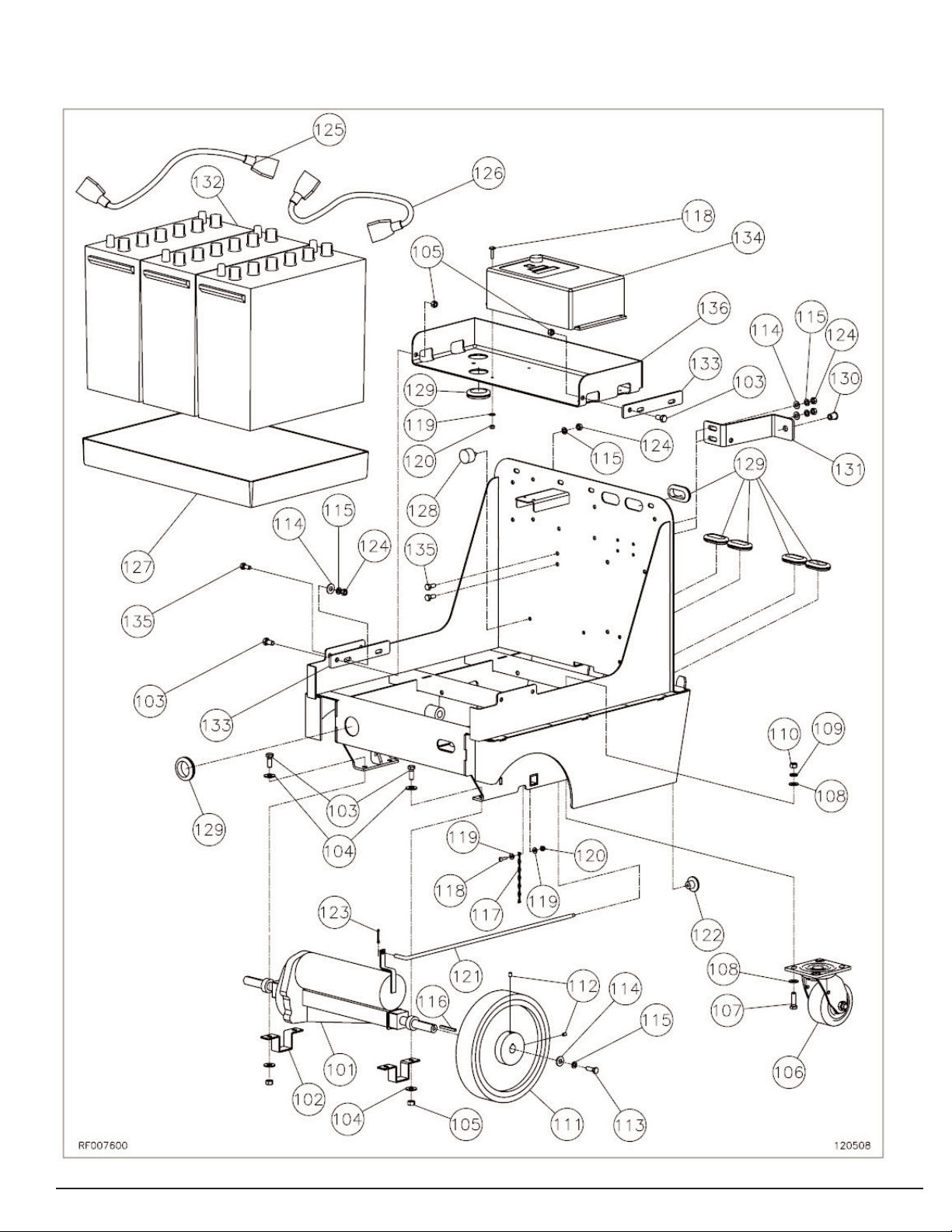
POWERGLIDE EXPRESS FRAME ASSEMBLY (1 OF 3)
27
010209

28
POWERGLIDE EXPRESS FRAME ASSEMBLY (1 OF 3)
Ref.Part # Description Qty.
101 MP253600 TRANSAXLE, WIRING ASM. 1
102 PG001801 BRACKET, TRANSAXLE,
POWERGLIDE, PAINTED 2
103 NB6042 SCREW, CAP, 3/8 X 1 6
104 NB3450 WASHER, FLAT, 3/8 8
105 NB3267 NUT, LOCK, 3/8 NC 6
106 MP144100 CASTER, 4”, SWIVEL, GREY,
W/SEAL 2
107 NB6044 SCREW, CAP, 3/8-16 X 1 1/4 8
108 MX1080 WASHER, FLAT, 3/8 16
109 MX1075 WASHER, LOCK, 3/8 8
110 NB046200 NUT, HEX, 3/8-16, GD5 8
111 MP206900 WHEEL, 10” X 2” POLYURETHANE 2
112 NB9302 SCREW, SET, 1/4-20 X 3/8, KNURL
CUP POIN 4
113 NB6545 SCREW, CAP, HH, 5/16-18 X 1 2
114 NB9267 WASHER, FLAT, 5/16 8
115 NB6111 WASHER, LOCK, 5/16 10
116 MP236800 KEY, 3/16 X 1 7/8 2
117 MP253700 CHAIN, #14, ZINC PLATED, SINGLE
JACK 6”
118 MX1025 SCREW, PAN HD, 10-24 X 3/4 5
119 NB9645 WASHER, FLAT, #10 6
120 NB9735 NUT, LOCK, 10-24, NYLON 5
121 PG015700 ROD, DISENGAGEMENT, BRAKE,
TRANSAXLE 1
122 MP208600 KNOB, PUSH/PULL, 1 3/8”O.D.
1/4-20 FEM. 1
123 NB022700 PIN, COTTER, 3/32 X 1” 1
124 NB3260 NUT, 5/16-18, NC 10
125 MP279800 CABLE, BATT./CONNECTOR, 2AWG 1
126 MP238200 CABLE, BATTERY, CONN., 2 AWG,
13.5”, LONG 1
127 MP275300 TRAY, BATTERY, PGX 1
128 MP199900 MOUNT, VIBRATION, STUD, 5/16-18 3
129 NB6514 GROMMET , 1 1/2 ID X 1/8 W X 1 3/4 D 7
130 NB6504 INSERT, 3/8-16, COMPRESSION
TYPE 1
131 MP112701 BRACKET, MOUNT, COVER, BACK,
FORMED 1
132 MP223600 BATTERY, 12V, 228AH, DEEP CYCLE,
SET OF 3 1
133 PG010601 BRACKET, ADJUSTMENT, CHARGER,
PAINTED 2
134 MP280000 CHARGER, BATTERY, 36V, ASM. 1
135 NB9745 SCREW, CAP, 5/16-18 X 3/4 6
136 MP112901 BRACKET, CHARGER, PGX 1
010209

POWERGLIDE EXPRESS FRAME ASSEMBLY (2 OF 3)
010209
29
RF007700

POWERGLIDE EXPRESS FRAME ASSEMBLY (2 OF 3)
Ref.Part # Description Qty.
200 PG013000 CABLE, BATT./CONNECTOR,
2AWG, PGX 1
201 NB048400 PIN, CLEVIS, 5/8 X 2 1/2 2
202 LX2105 CLIP, HITCH PIN, STRAIN RELIEF 2
203 MP221300 WASHER, PIVOT, NYLON 2
204 NB054800 HOOK, J, 3/8-16 X 7 1/4 1
205 PG015401 BRACE, CROSS, REAR, WELD. 1
206 PG015800 ARM, LINK, ADJUSTMENT, SPRING,
WELDMENT 1
207 NB046200 NUT, HEX, 3/8-16, GD5 2
208 PG015600 ARM, LIFT, POWERGLIDE, ASM. 2
209 NB052000 SCREW, CAP, 3/8 X 1 3/4 6
210 NB3265 WASHER, FLAT, 3/8 6
211 MX1080 WASHER, LOCK, 3/8 4
212 NB9735 NUT, LOCK, 3/8 NC 1
213 MP279200 SPRING, GAS, 3”, 1200N 1
214 MP234100 SPRING, EXTENSION, 1.75”O.D. X
8”L 1
215 NB9745 SCREW, CAP, 5/16-18 X 3/4 7
216 NB6111 WASHER, LOCK, 5/16 9
217 NB3260 NUT, 5/16-18, NC 8
218 MP206800 BALL, STUD, 13MM 2
219 MP208000 PIN, RETAINER, SPRING, GAS 2
220 NB9267 WASHER, FLAT, 5/16 2
221 PG000900 BRACE, CROSS, FRONT, WELD. 1
222 MP279700 CABLE, BATT./CONNECTOR. 2AWG 1
223 MP221700 SPACER, MICRO SWITCH 2
224 MP036200 SWITCH, MICRO, 12V, 15A 2
225 NB048200 SCREW, PAN HD, #4-40 X 1 1/2,
PHILLIPS 2
226 NB048300 WASHER, FLAT, #4 2
227 NB007000 NUT, LOCK, NYLON, 4-40 2
228 NB002900 RING, RETAINER, 1/2”, E-STYLE 4
229 MP241100 BRACKET, LIFT, ACTUATOR, RIGHT,
ASM. 1
Ref.Part # Description Qty.
230 MP241000 BRACKET, LIFT, ACTUATOR, LEFT,
ASM. 1
231 MP240900 BRACKET, ADJUSTMENT, PAD
PRESSURE, ASM. 1
232 PG004700 ARM, LIGY, ACTUATOR, WELD. 1
233 MP280200 ACTUATOR, LINEAR, 123MM, 24V,
ASM. 1
234 MP241900 SP ACER, ACTUATOR, NYLON 1
235 NB048600 SCREW, SHOULDER, 8mm X 40mm
X 6MM 2
236 NB048900 WASHER, LOCK, 6mm 2
237 NB048700 WASHER, FLAT, 6mm 2
238 NB048800 NUT, HEX, 6mm 2
239 PG004800 PIVOT, ADJUSTMENT, PAD
PRESSURE, WELD. 1
240 PG003400 SPACER, ROD, ADJUST.,
POLYETHYLENE 1
241 PG003200 ROD, ADJUST., PAD PRESSURE 1
242 MP208700 KNOB, TAPERED, 1 3/8OD, 3/8-16
FEMALE 1
243 NB9000 SCREW, CAP, 1/4-20 X 1 1/2, GD5 1
244 NB3275 NUT, LOCK, 1/4 1
247 NB9560 SCREW, TRUSS HD, 10-24 X 1 1/2 2
248 NB9645 WASHER, FLAT, #10 2
249 NB9735 NUT, LOCK, 10-24, NYLON 2
250 MX1080 WASHER, FLAT, 3/8 6
010209
30

POWERGLIDE EXPRESS FRAME ASSEMBLY (3 OF 3)
RF007800
123108
31

Ref.Part # Description Qty.
300 MP112601 P ANEL, ACCESS, PAINTED 1
301 NB043600 SCREW, PAN HD, HI-LO, #8 X 3/8” 10
302 NB3260 NUT, 5/16-18, NC 16
303 NB6111 WASHER, LOCK, 5/16 20
304 NB9745 SCREW, CAP, 5/16-18 X 3/4 20
305 PG010301 BRACKET, PLATE, HANDLE, LEFT,
FORMED 1
306 PG010302 BRACKET, PLATE, HANDLE, RIGHT,
FORMED 1
307 MP112801 PLATE, MOUNT, HANDLE 1
308 MP233800 CONTROLLER, TRACTION, 36V 1
309 NB5350 SCREW, MACHINE, TH, 10-24 X 1 2
310 MP234300 CORD, 14/3, SJT, 6’7” 1
311 NB9735 NUT, LOCK, 10-24, NYLON 8
312 PG010201 BRACKET, CONTROLLER 1
313 NB6514 GROMMET , 1 1/2 ID X 1/8 W X 1 3/4 D 1
314 MP237400 GRIP, HANDLE, POWERGLIDE 2
315 MP111600 CONTROLLER, MOTION, WIG-WAG,
SUB-ASM. 1
316 PG010700 PANEL, DASH, LEFT, PGX, ASM. 1
317 PG010800 PANEL, DASH, RIGHT, PGX, ASM. 1
318 PG013300 SHUNT, PGX, ASM. 1
319 NB6110 WASHER, LOCK, 1/4 5
320 MX1045 NUT, HEX, 1/4-20 2
321 MX1025 SCREW, PAN HD, 10-24 X 3/4 2
324 MP207000 SOLENOID, 36VDC, SPNO 1
325 NB3350 WASHER, FLAT, 1/4 4
POWERGLIDE EXPRESS FRAME ASSEMBLY (3 OF 3)
Ref.Part # Description Qty.
326 NB003200 BOLT, HEX, 1/4-20 X 5/8 2
327 NB3275 NUT, LOCK, 1/4 4
328 X X
329 MP234400 FUSE, CURRENT LIMITING, 50 AMP 1
330 MP234500 FUSEBLOCK 2
331 NB5350 SCREW, MACHINE, TH, 10-24 X 1 4
332 NB9645 WASHER, FLAT, #10 2
334 MP234200 INLET, POWER, AC, SCREW MOUNT 1
335 NB9200 SCREW, MACHINE, ROUND HD,
6-32 X 5/8 2
336 NB007100 WASHER, FLAT, #6 2
337 NB020800 NUT, LOCK, NYLON, 6-32 2
338 MP207100 SWITCH, PUSH-PULL, SEALED 1
339 PG009000 COVER, DASH, PGX, TRIMMED 1
341 NB9267 WASHER, FLAT, 5/16 4
342 PG013900 COVER, BATTERY, PGX, ASM. 1
343 PG011500 ROD, HANDLE, INNER, PGX 1
344 NB031200 BOLT, HEX, 5/16-18 X 5/8”, SS 4
345 PG009100 COVER, BOTTOM, PGX, TRIMMED 1
346 NB6530 SCREW, CAP, HH, 1/4-20 X 1 4
347 NB6535 SCREW, CAP, HH, 1/4-20 X 3/4 1
348 PG008800 COVER, BACK, PGX, 1
PG014900 COVER, BACK, PGX, MANUAL LIFT 1
349 NB6501 INSERT , 1/4-20, COMPRESSION TYPE 2
350 MP276200 KNOB, 3/8-16 STUD 1
32
123108

POWERGLIDE EXPRESS FRAME ASSEMBLY MANUAL LIFT
RF011000
33
010209

34
POWERGLIDE EXPRESS FRAME ASSEMBLY MANUAL LIFT
Ref.Part # Description Qty.
200 PG013000 CABLE, BATT./CONNECTOR,
2AWG, PGX 1
201 NB048400 PIN, CLEVIS, 5/8 X 2 1/2 2
202 LX2105 CLIP, HITCH PIN, STRAIN RELIEF 2
203 MP221300 WASHER, PIVOT, NYLON 2
204 NB054800 HOOK, J, 3/8-16 X 7 1/4 1
205 PG015401 BRACE, CROSS, REAR, WELD. 1
206 PG015800 ARM, LINK, ADJUSTMENT, SPRING,
WELDMENT 1
207 NB046200 NUT, HEX, 3/8-16, GD5 2
208 PG015600 ARM, LIFT, POWERGLIDE, ASM. 2
209 NB052000 SCREW, CAP, 3/8 X 1 3/4 6
210 NB3265 WASHER, FLAT, 3/8 6
211 MX1080 WASHER, LOCK, 3/8 4
212 NB9735 NUT, LOCK, 3/8 NC 1
213 MP279200 SPRING, GAS, 3”, 1200N 1
214 MP234100 SPRING, EXTENSION, 1.75”O.D. X
8”L 1
215 NB9745 SCREW, CAP, 5/16-18 X 3/4 7
216 NB6111 WASHER, LOCK, 5/16 9
217 NB3260 NUT, 5/16-18, NC 8
218 MP206800 BALL, STUD, 13MM 2
219 MP208000 PIN, RETAINER, SPRING, GAS 2
220 NB9267 WASHER, FLAT, 5/16 4
221 PG000900 BRACE, CROSS, FRONT, WELD. 1
222 MP279700 CABLE, BATT./CONNECTOR. 2AWG 1
223 MP221700 SPACER, MICRO SWITCH 2
224 MP036200 SWITCH, MICRO, 12V, 15A 2
225 NB048200 SCREW, PAN HD, #4-40 X 1 1/2,
PHILLIPS 2
226 NB048300 WASHER, FLAT, #4 2
227 NB007000 NUT, LOCK, NYLON, 4-40 2
228 NB002900 RING, RETAINER, 1/2”, E-STYLE 4
229 MP241100 BRACKET, LIFT, ACTUATOR, RIGHT,
ASM. 1
Ref.Part # Description Qty.
230 MP241000 BRACKET, LIFT, ACTUATOR, LEFT,
ASM. 1
231 MP240900 BRACKET, ADJUSTMENT, PAD
PRESSURE, ASM. 1
232 PG004700 ARM, LIFT, ACTUATOR, WELD. 1
233 PG014500 PIN, PIVOT, LIFT, MANUAL, PG 2
234 NB4000 CAPLUG, .312 X 1/2”, YELLOW,
VINYL 1
235 PG014701 BRACKET, LIFT, MANUAL, PG 1
236 PG014401 ARM, LIFT, MANUAL, PG 1
237 NB6545 SCREW, CAP, HH, 5/16-18 X 1 2
238 NB6110 WASHER, LOCK, 1/4 3
239 PG004800 PIVOT, ADJUSTMENT, PAD
PRESSURE, WELD. 1
240 PG003400 SPACER, ROD, ADJUST.,
POLYETHYLENE 1
241 PG003200 ROD, ADJUST., PAD PRESSURE 1
242 MP208700 KNOB, TAPERED, 1 3/8OD, 3/8-16
FEMALE 1
243 NB9000 SCREW, CAP, 1/4-20 X 1 1/2, GD5 1
244 NB3275 NUT, LOCK, 1/4 1
245 NB055200 SCREW, 1/4-20 X 5/8, CS, SS 1
246 NB6530 SCREW, CAP, HH, 1/4-20 X 1 2
247 NB9560 SCREW, TRUSS HD, 10-24 X 1 1/2 2
248 NB9645 WASHER, FLAT, #10 2
249 NB9735 NUT, LOCK, 10-24, NYLON 2
250 MX1080 WASHER, FLAT, 3/8 6
252 PG014601 LATCH, LIFT, MANUAL, PG 1
253 PG014200 HANDLE, LIFT, MANUAL, WELDMENT 1
254 MP282600 GRIP, HAND, VINYL, YELLOW
010209

POWERGLIDE EXPRESS WIRING DIAGRAM
35
070208

36
POWERGLIDE EXPRESS WIRING DIAGRAM MANUAL LIFT
070208

Limited Warranty
PowerGlide Express Battery
Burnisher
PowerGlide Warranty:
The PowerGlide Express Battery Burnisher is
warranted to be free of defects in materials and
workmanship for a period of three (3) years from the
date of purchase by the original owner apart from the
EXCLUSIONS and EXCEPTIONS noted below.
TO QUALIFY FOR THIS WARRANTY:
1) Machine must be registered at the time of purchase on
a form provided by Amano Pioneer Eclipse
Corporation. Your Amano Pioneer Eclipse Distributor
is responsible for the registration of your machine.
Please cooperate with your Distributor in supplying
necessary information on the card.
2) The machine must have been purchased from Amano
Pioneer Eclipse or an authorized Amano Pioneer
Eclipse Distributor.
3) This warranty extends to the original purchaser only
and is not transferable to subsequent owners.
EXCLUSIONS:
1) Parts that fail through normal wear by reason of their
characteristics including, but not limited to, pads, skirts,
air filter, etc., are not warranted.
2) Parts affected by misuse, neglect, abuse or improper
maintenance are not warranted.
EXCEPTIONS:
1) Batteries are warranted by the manufacturer for one
(1) year.
Rotational molded parts and the machine frame are
warranted for five (5) years.
THE OBLIGATION OF AMANO PIONEER ECLIPSE
CORPORATION:
1) The obligation of Amano Pioneer Eclipse under this
warranty is limited to repairing or replacing, at its
option, any part which is proven to be defective in
material or workmanship under normal use for the
applicable period stated above.
2) Warranty repairs will be made by your Amano Pioneer
Distributor without charge for parts and labor.
3) Parts repaired or replaced under this warranty are
warranted only during the balance of the original
warranty period. All defective parts replaced under
these warranties become the property of Amano
Pioneer Eclipse.
4) All defective parts must be returned to an Authorized
Amano Pioneer Eclipse Distributor for credit.
WARRANTY SERVICE:
To obtain warranty service, take your machine and proof of
purchase to any authorized Amano Pioneer Eclipse
Distributor. Amano Pioneer Eclipse will not reimburse
expenses for service calls or travel. For the Distributor in
your area, call Amano Pioneer Eclipse Customer Service
Department at 800-367-3550 or 1-336-372-8080. If you
are dissatisfied with the service that you receive, call or
write Amano Pioneer Eclipse Customer Service
Department for further assistance.
DISCLAIMER OF CONSEQUENTIAL:
AMANO PIONEER ECLIPSE DISCLAIMS ANY
RESPONSIBILITY FOR LOSS OF USER TIME OF THE
AMANO PIONEER ECLIPSE MACHINE OR ANY OTHER
INCIDENTAL OR CONSEQUENTIAL DAMAGE EXCEPT
AS STATED IN THE WARRANTY APPLICABLE TO EACH
MACHINE. EXCEPT AS STATED IN SUCH
WARRANTIES, THE COMPANY DOES NOT OTHERWISE WARRANTANY MACHINE AND NO WARRANTY,
EXPRESS, IMPLIED OR STATUTORY IS MADE BY THE
COMPANY.
Copyright 2007 Amano Pioneer Eclipse Corporation
LT047500-G; 12/31/08
37

© 2007
Amano Pioneer Eclipse Corporation
P.O. Box 909
Sparta, NC 28675
1-336-372-8080
1-800-367-3550
www.pioneer-eclipse.com
Article #:
Serial #:
DOM:
Built in NC, USA
 Loading...