

Pioneer DJ XPRS10, XPRS12, XPRS15, XPRS115S, XPRS215S Operating Instructions
XPRS Series
XPRS10
XPRS12
XPRS15
XPRS115S
ACTIVE LOUDSPEAKER / ACTIVE SUBWOOFER
HAUT-PARLEUR ACTIF / CAISSON DE BASSES ACTIF
AKTIVLAUTSPRECHER / AKTIV-SUBWOOFER
DIFFUSORE ATTIVO / SUBWOOFER ATTIVO
ACTIEVE LUIDSPREKER / ACTIEVE SUBWOOFER
ALTAVOZ ACTIVO / ALTAVOZ DE SUBGRAVES ACTIVO
ALTO-FALANTE ATIVO / SUBWOOFER ATIVO
АКТИВНЫЙ ГРОМКОГОВОРИТЕЛЬ /АКТИВНЫЙ САБВУФЕР
アクティブラウド スピーカー/アクティブ サブウーファー
XPRS215S
http://pioneerproaudio.com
The Pioneer DJ support site shown above offers FAQs, information on software and various other types of
information and services to allow you to use your product in greater comfort.
Le site de support DJ de Pioneer indiqué ci-dessus propose une FAQ, des informations sur le logiciel et divers
types d’informations et de services qui permettent une utilisation plus confortable de ce produit.
Die oben gezeigte Pioneer DJ-Support-Website enthält häufig gestellte Fragen, Informationen über Software
und andere wichtige Informationen und Dienste, die Ihnen helfen, Ihr Produkt optimal zu verwenden.
Il sito di supporto DJ Pioneer indicato qui sopra offre una sezione FAQ, informazioni sul software ed
informazioni e servizi di vario tipo, per permettere un uso più confortevole dei nostri prodotti.
De bovengenoemde Pioneer DJ ondersteuningswebsite biedt een overzicht van de vaak gestelde vragen,
informatie over software en allerlei andere soorten informatie en diensten die u in staat stellen dit product met
meer gemak te gebruiken.
El sitio de asistencia Pioneer DJ mostrado arriba ofrece las preguntas frecuentes, información del software y
varios otros tipos de información y servicios que le permitirán usar su producto con mayor confort.
O site de suporte da Pioneer DJ mostrado acima oferece FAQs, informações sobre o software e outros tipos
de informações e serviços para permitir utilizar o produto com um maior conforto.
На указанном выше сайте поддержки Pioneer DJ содержатся раздел часто задаваемых вопросов,
информация по программному обеспечению, а также различные другие типы информации и услуг,
позволяющие использовать ваше изделие наиболее эффективно образом.
上記のPioneerDJサポート サイトでは、困ったときのよくある質問やソフトウェア の情報など、より快適に製品をお使い
いただくための各種情報やサービスを提供しております。
Português Русский
商品相談・修理受付・付属品購入窓口のご案内
お取り扱いにお困りのとき、本書の巻末をご覧ください。
Operating Instructions
Mode d’emploi
Bedienungsanleitung
Istruzioni per l’uso
Handleiding
Manual de instrucciones
Manual de instruções
Инструкции по эксплуатации
取扱説明書
保証書付き
日本語Français Deutsch ItalianoEnglish Nederlands Español
Introduction
XPRS215S
4
1
2
3
XPRS10, XPRS12, XPRS15
4
3
XPRS115S
How to Read This Document
Thank you for purchasing a Pioneer DJ product. To ensure you can maximize the functions of this device and use them effectively, please
read this Operating Instructions and Important Safety Precautions thoroughly for correct use.
Please be sure to read in particular the Important Safety Precautions, and keep the Operating Instructions and Important Safety
Precautions together with the Warranty.
For more information on installation, please read the Installation Manual.
http://pioneerproaudio.com
Main Features
2 400-W high output and high sound quality are achieved
by mounting a D-class amplifier module of the professional
amplifier leading company Powersoft in a wooden cabinet
featuring outstanding acoustic characteristics.
The XPRS can be used not only as a stationary sound system in
a stationary facility but also as sound equipment for events as it
can be easily transported and set up quickly.
High sound quality design of wooden cabinet structure
g
featuring outstanding acoustic characteristics
A wooden cabinet is employed to provide superior sound quality
in all models.
The cabinet made of highly rigid materials features outstanding
acoustic characteristics and reproduces clear sound quality
ranging from a minute sound to a powerful sound.
Equipped with a high-efficiency and high-power class-D
g
amplifier module
The XPRS is equipped with a D-class amplifier module realized
by the technology of Powersoft and achieves a 2 400-W (at peak)
high output comparable with that of a large power amplifier.
A very high power efficiency can reduce the energy required to
get the same output power.
Advanced protective functions preventing field problems
g
A variety of functions such as status monitoring and limiter
functions reliably protect the driver, amplifier, and power supply
by using advanced DSP control. Protective circuits designed to
meet the reliability requirements for professional use prevent
problems in the field.
A variety of I/O terminals enabling flexible system connections
g
A mixing function is available which mixes multiple input
sources and outputs them. In addition, a through output terminal
is available to make it easy to connect with full-range speakers
and multiple subwoofers.
Four EQ modes enabling a quick system setup (full-range
g
models)
Four EQ modes of FLAT, BASS+, SPEECH, and WEDGE are
available which enable selection of the optimum acoustic
characteristic to suit the application by just selecting a switch.
Multi-angle pole socket enabling installation of a pole at
g
two angles (full-range models)
Two angles of 0 and 7 can be selected to suit the size of the venue
when installing the speakers using a pole.
Confirm All Accessories
Power cords
Installation and Operation Manual (this document)
Important Safety Precautions
The contents of the warranty for the United States and Canada are
provided on the last pages of the instructions in English and French.
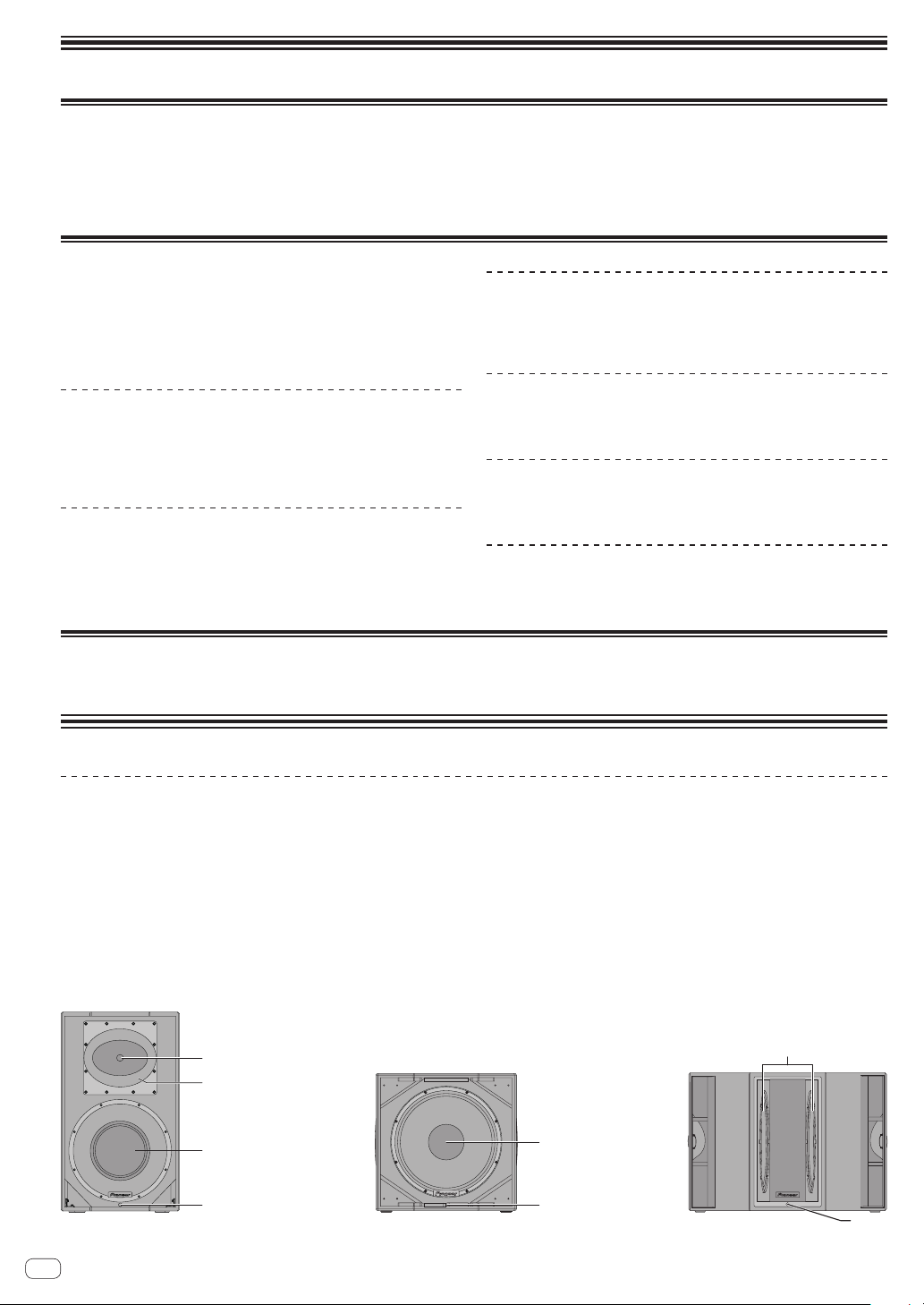
Names and Functions of Parts
Front Panel Facilities
Tweeter
1
1-inch throat 1.75-inch diaphragm compression driver
Rotatable horn (XPRS12, XPRS15)
2
This is a constant directivity horn that can be rotated.
• Factory default directivity: 90 degrees horizontally and 60
degrees vertically
• Directivity when turned 90 degrees: 60 degrees horizontally
and 90 degrees vertically
Horn (XPRS10)
2
This is a constant directivity horn with directivity of 90 degrees
horizontally and 60 degrees vertically.
* Horn rotation is not possible for XPRS10.
Woofer
3
FRONT LED indicator
4
This is a white LED indicator. Lighting is in accordance with the
FRONT LED setting on the rear panel.
For details on the settings, see the explanation of the rear panel.
3
2way full-range model
En
2
Subwoofer model
Subwoofer model
4

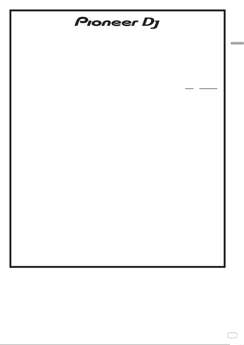
Rear Panel Facilities (Full-Range Models)
3
4
b
a
9
c
e
d
g
f
7
English
5
6
7
8
1
2
POWER switch
1
Turns this speaker’s power on and off.
AC IN
2
Connect the power cord to AC IN and then to the power outlet.
Fuse holder
3
Power indicator
4
Lights in blue when the power is turned on.
MASTER LEVEL
5
Adjusts the output level.
EQ MODE SELECT
6
Switches to four EQ modes (FLAT, BASS+, SPEECH, and
WEDGE). For details, see “EQ MODE Settings” on page 6.
INPUT LEVEL knob
7
Adjusts the input signal level.
GAIN knob (for MIC/LINE1 only)
8
Select the gain according to the output signal level of the device
to be connected. The selected gain is added to the signal input to
this unit.
• To input the signal of a line output device to this speaker,
select [0 dB] or [12 dB].
• To input a low-level output signal such as that of a
microphone to this unit, select [24 dB] or [36 dB].
SIGNAL indicator
9
A green indicator lights when an input signal is detected.
MIC/LINE1 and LINE2 INPUT
a
Both the XLR connector (balanced) and 1/4” TRS (balanced
type PHONO) are supported. The XLR connector consists of 1
“ground,” 2 “hot,” and 3 “cold.”
LINK
b
This is the XLR output connector (balanced). A signal input to
XLR INPUT will be output directly. (A signal input to AUX IN of
LINE2 will not be output.)
9
a
b
LIMIT indicator
c
Lights in red when the built-in limiter is activated or when the
input level is too high and the sound is distorted. When that
happens, lower the output level of the connected device or lower
the input level or master level of this unit.
EXT SUB MODE
d
Select [ ]for normal use.
Select [ ] when using a subwoofer.
FRONT LED
e
Selects the display setting of the FRONT LED indicator (white).
[POWER] Lights when the power is turned on.
[LIMIT] Lights when the limiter is activated.
[OFF] The FRONT LED does not light.
AUX IN
f
These are the RCA input connectors (unbalanced).
A stereo signal input to AUX IN is mixed to a monaural signal (not
output from the LINK connector).
MIX OUT
g
This is the XLR output connector (balanced). Mixes the signal
input to MIC/LINE1 and Line2 and then outputs it.
A signal adjusted in MIC GAIN and INPUT LEVEL is output.
CAUTION
When the FRONT LED setting is set to [OFF] and [LIMIT],
the speaker may appear the same as when the power plug
is disconnected from the power outlet depending on the
specification of the product, but the power is not shut off. If you
wish to shut off the power to the woofer completely, you must
disconnect the power plug from the power outlet. Install the
speaker near a power outlet so the power plug can easily be
accessed. Leaving the power plug inserted in a power outlet for a
long period of time may cause fire.
En
3

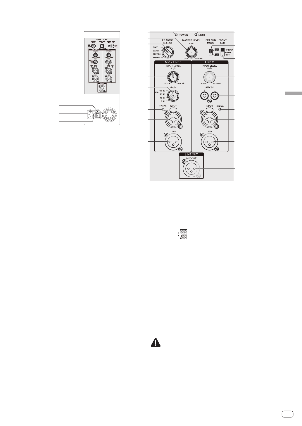
Rear Panel Facilities (Subwoofer Model)
3
4
a
c
b
9
8
7
1
2
5
6
7
8
9
POWER switch
1
Turns this speaker’s power on and off.
AC IN
2
Connect the power cord to AC IN and then to the power outlet.
Fuse holder
3
Power indicator
4
Lights in blue when the power is turned on.
MASTER LEVEL
5
Adjusts the output level.
CROSS OVER
6
Selects the cut-off frequency of the low pass filter for the
subwoofer from 80 Hz, 100 Hz, 120 Hz, and 150 Hz.
100 Hz is recommended when using the subwoofer with the
XPRS Series full-range speakers.
SIGNAL indicator
7
A green indicator lights when an input signal is detected.
LINE1 and LINE2 INPUT
8
Both the XLR connector (balanced) and 1/4” TRS (balanced
type PHONO) are supported. The XLR connector consists of 1
“ground,” 2 “hot,” and 3 “cold.”
LINK
9
This is the XLR output connector (balanced). A signal input to
XLR INPUT will be output directly.
LIMIT indicator
a
Lights in red when the built-in limiter is activated or when the
input level is too high and the sound is distorted. When that
happens, lower the output level of the connected device or lower
the input level or master level of this unit.
PHASE
b
Switches the polarity for the subwoofer. Select the one that
improves the playback of low frequencies when using the
subwoofer with other speakers.
FRONT LED
c
Selects the display setting of the FRONT LED indicator (white).
[POWER] Lights when the power is turned on.
[LIMIT] Lights when the limiter is activated.
[OFF] The FRONT LED does not light.
CAUTION
When the FRONT LED setting is set to [OFF] and [LIMIT],
the speaker may appear the same as when the power plug
is disconnected from the power outlet depending on the
specification of the product, but the power is not shut off. If you
wish to shut off the power to the woofer completely, you must
disconnect the power plug from the power outlet. Install the
speaker near a power outlet so the power plug can easily be
accessed. Leaving the power plug inserted in a power outlet for a
long period of time may cause fire.
En
4
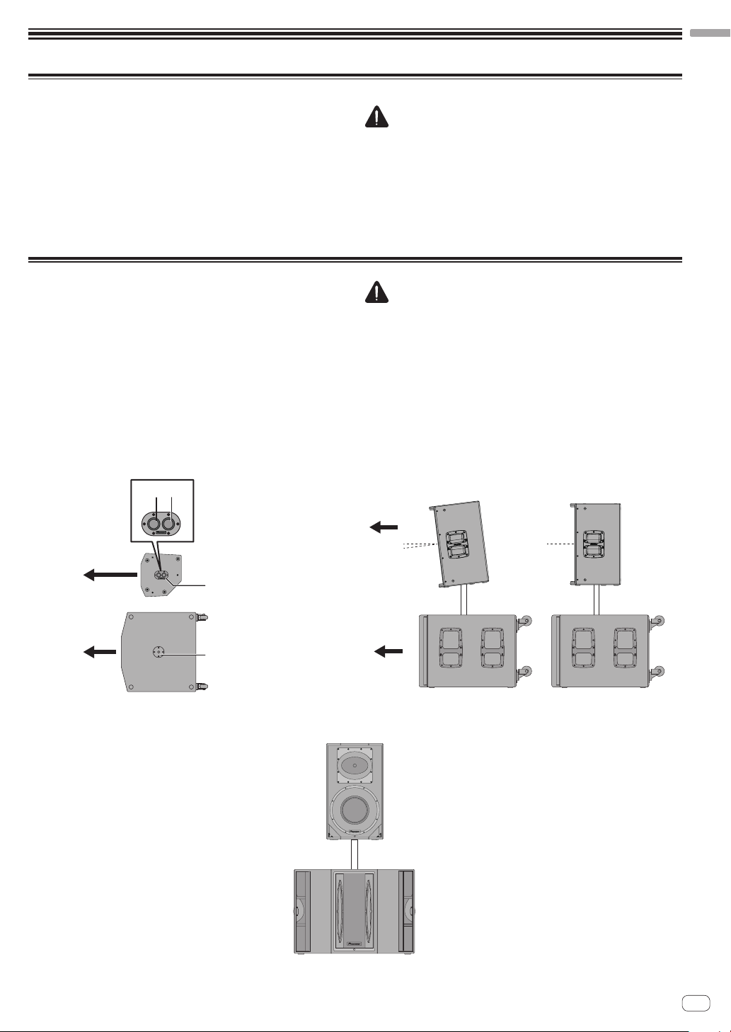
Installation and Connections
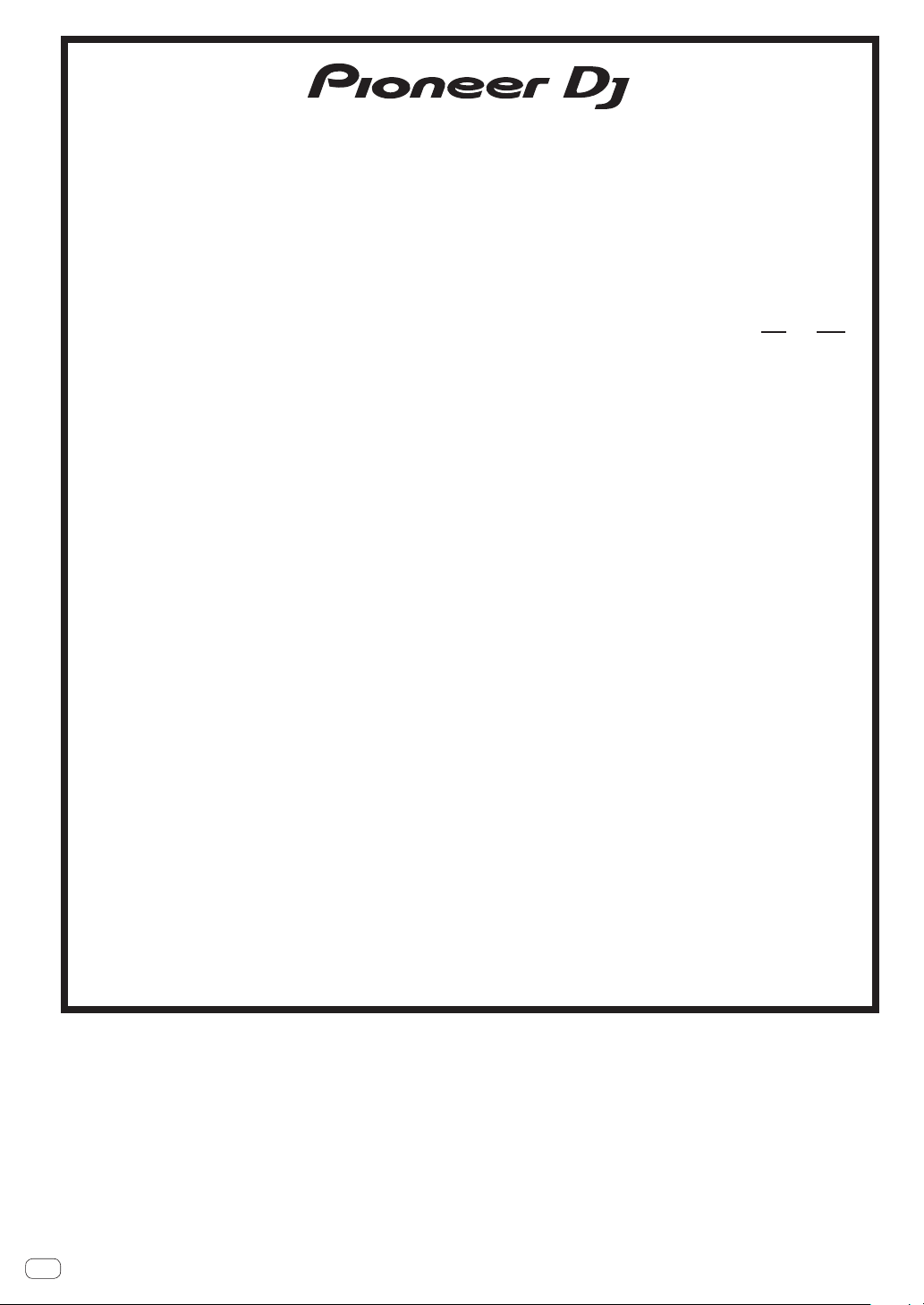
Multi-angle pole socket
Installation using a speaker pole
XPRS215S
How to Install
The playback sound of the speaker is subtly influenced by the conditions of the
listening room. Carefully consider the installation location before installing
the speaker so that it can be used in the best conditions. Pioneer DJ will not
be liable for any damages arising from the use of the speaker (including but
not limited to loss of business opportunities), regardless of the installation
method.
Use the handles on the top or the sides of the speaker when moving and
installing the speaker.
Installation Using a Speaker Pole
XPRS12/XPRS15
The full-range models of the XPRS series have a 35-mm-diameter multi-angle
pole socket on the bottom surface and can be installed downward at an angle
of 0° or 7° to the floor surface.
The subwoofer model of the XPRS series has an M20 screw-in pole socket on
the top surface and the pole can be secured firmly.
The combinations shown in the following figures are recommended for the
XPRS series. Use with a combination other than those may result in the
speakers toppling over, causing damage or injury. To use a speaker pole,
check the cautions on the right and perform the installation safely.
CAUTION
When standing or laying the XPRS115S, XPRS215S, take care that the
!
casters do not slip and cause an injury.
To promote proper cooling, please assure that sufficient space
!
is preserved between the speakers and nearby walls or other
components (minimum 30 cm or more above, behind, and to right
and left sides of each speaker). Leaving insufficient space between
the speaker and walls or other components may lead to rising interior
temperatures, leading to malfunction or damage.
CAUTION
At least two persons should together lift the speaker to install. Give
!
sufficient consideration to safety when performing the work.
For the speaker pole, use a 35-mm-diameter, one-side M20 screw-in
!
speaker pole. Use a commercially-available product with a length
of 900 mm or less. Pioneer DJ will not be liable for any damages
(including but not limited to loss of business opportunities) arising
from the use of a speaker pole other than specified.
Install the subwoofer in a stable location and secure the speaker pole
!
firmly.
Ensure that there is no danger of toppling.
!
Cables should be taped or tied together with cable ties so as to avoid
!
the danger of tripping on the cables and toppling the speaker.
English
Front
7° 0°
35-mm-diameter
pole socket
M20 screw-in
pole socket
Front
XPRS12, XPRS15
7°
0°
En
5

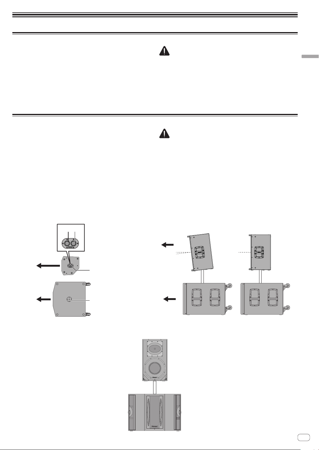
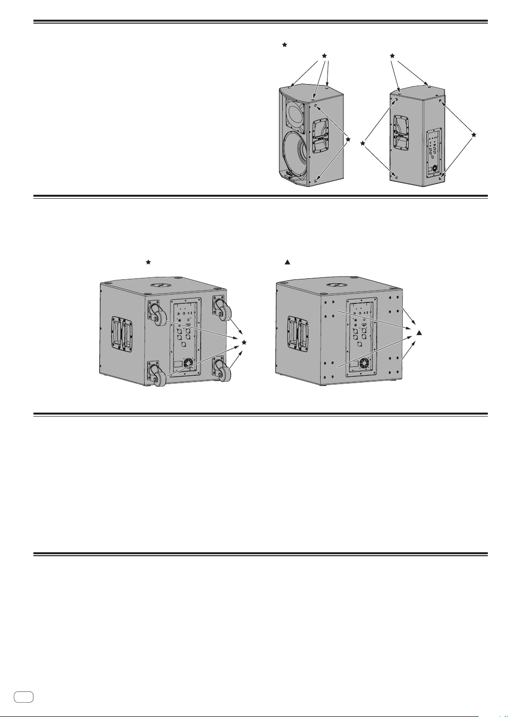
Installation Using the Rigging Points on the Speaker
:Rigging points
:Caster :M5 hex screw (thread length 25 mm)
The full-range models have suspension-mounting rigging points on
!
them. The speaker can be suspended using commercially-available
eye bolts. The rigging point has an M10 screw hole (for an eye bolt with
a thread length of 30 mm to 50 mm).
When installing the speaker suspended, ask a qualified technician to
!
perform the work.
Remove the screws from the rigging points on the speaker and attach
!
eye bolts. Do not use the speaker while the screws are removed. The
sound will be adversely affected by air leakage.
Be sure to use at least three rigging points to suspend the speaker.
!
Furthermore, be sure to also implement an extra safety measure such
as using a wire.
Use brackets, wires, and a wall or ceiling strong enough to bear the
!
weight of the speaker. Ask for commercially-available brackets at the
shop where you purchased the speaker.
Be sure to confirm the safety after installing the speaker and
!
periodically thereafter.
Casters of the subwoofer model
The subwoofer model comes with casters that allow you to easily move it around.
!
To use it as a fixed installation, you can remove the casters.
!
When using it with the casters removed, be sure to put back the caster fixing screws.
!
If you use it with the screws removed, the sound quality will be affected by air leakage.
EQ MODE Settings
Four EQ modes (FLAT, BASS+, SPEECH, and WEDGE) are available for the full-range models. EQ MODE can be selected from four
options using the [EQ MODE SELECT] switch. Select the best mode according to your preferences and the usage situation.
FLAT
Reproduces the input sound faithfully. (Factory default setting)
BASS+
This setting increases the presence of low frequencies and reproduces powerful dance music at a club, etc.
SPEECH
This setting emphasizes the voice frequencies to make it easy to listen to the voice of a lecturer, etc.
WEDGE
This setting suppresses the excessive boost in the low frequencies that occurs when the speaker is installed on the floor surface as a
floor monitor.
Connections
When making or changing connections, always turn off the power and disconnect the power cord from its outlet.
Also, be sure to read the operating instructions for the other components to which you are connecting these speakers.
Do not connect the power cord until all other connections are completed.
Use only the furnished accessory power cord.
En
6
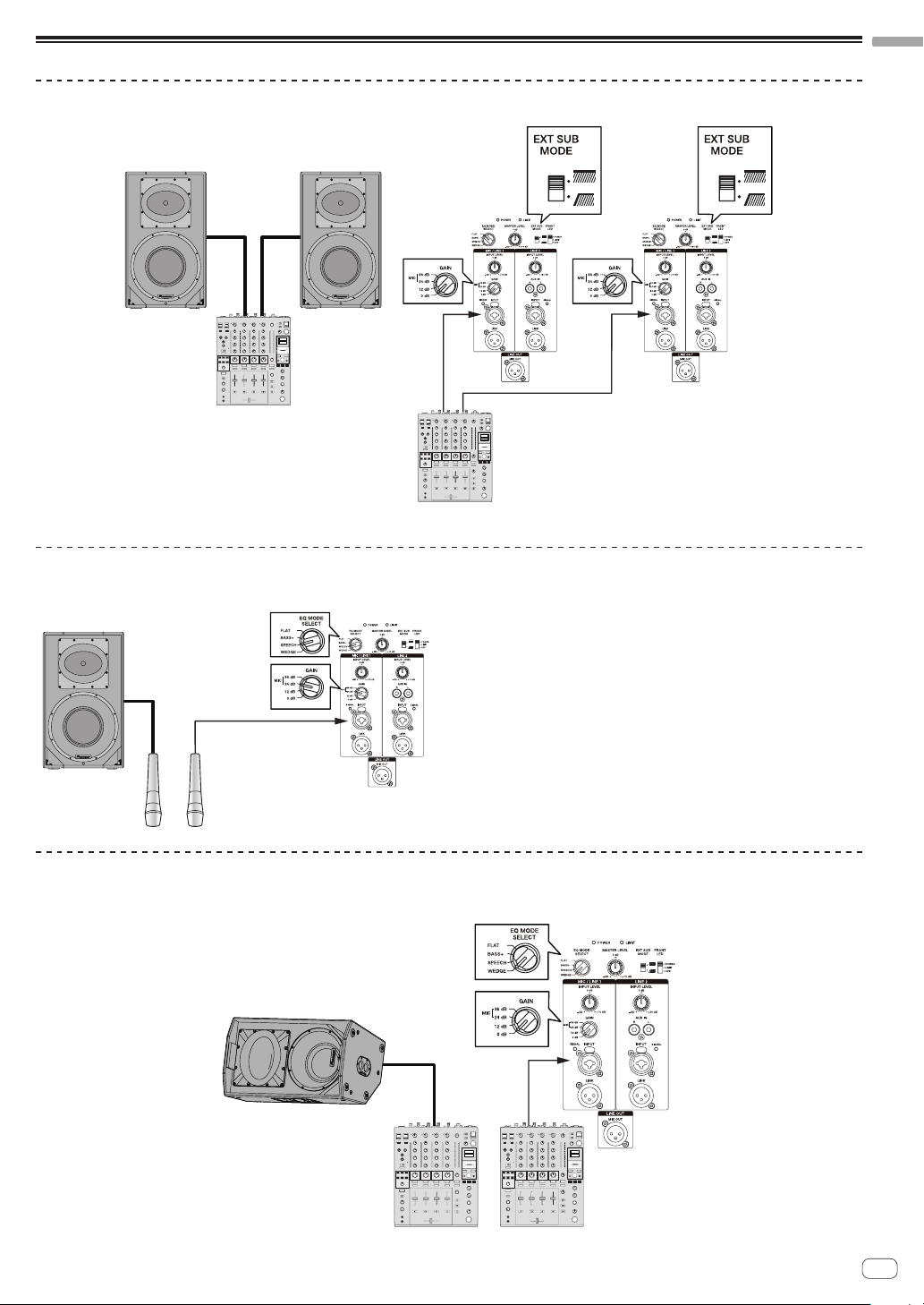
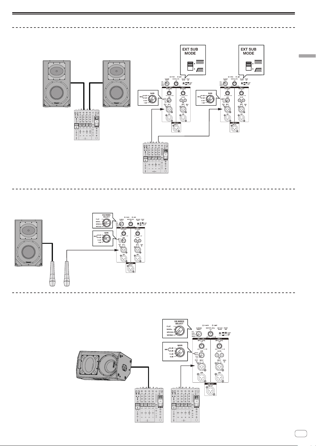
Setup example
General Stereo System
Amplifier connection
0 dB
DJ mixer, etc.
DJ mixer, etc.
System with Only a Microphone Connected
It is recommended to set EQ MODE SELECT to SPEECH.
Amplifier connection
EQ mode:
SPEECH
GAIN selection
Note:
To prevent feedback howling
Use the microphone with it’s directionality out of line with the
!
speaker’s output direction. For example, use the microphone from
behind the speaker, or change the direction of the microphone.
Use the microphone with the GAIN setting and INPUT LEVEL knob set
!
to appropriate positions.
English
System for Stage Monitor
Setting EQ MODE SELECT to WEDGE is recommended.
Amplifier connection
DJ mixer, etc.
En
7
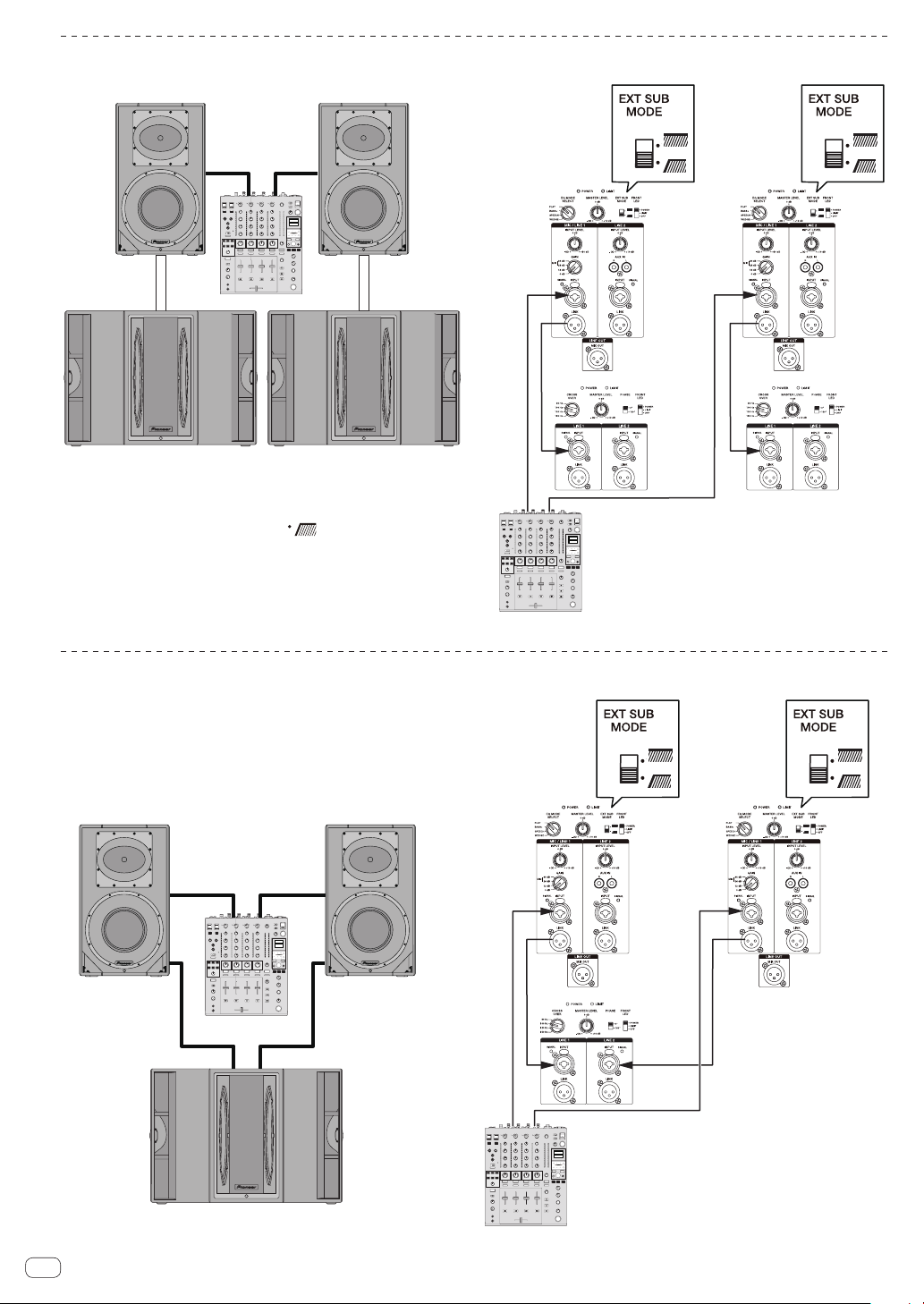
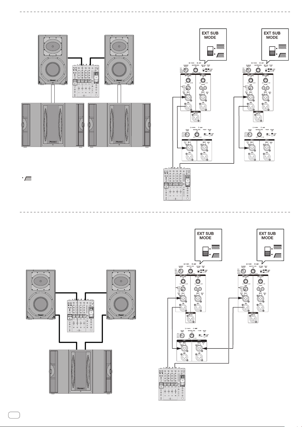
System with Subwoofer Connected
XPRS12 or XPRS15 XPRS12 or XPRS15
DJ mixer, etc.
Amplifier connection
DJ mixer, etc.
XPRS215S XPRS215S
When using the speaker with the XPRS series, it is recommended to set
EXT SUB MODE of a full-range model to [
the subwoofer model to 100 Hz.
] and set CROSS OVER of
System with XPRS215S Mono Mix Connected
Amplifier connection
XPRS12 XPRS12
DJ mixer, etc.
DJ mixer, etc.
XPRS215S
En
8

Additional Information
Troubleshooting
If you think you are experiencing a malfunction with this unit, check the following items. Also check other devices connected to the unit. If the problem
!
persists, consult your dealer for service.
On occasion, the unit may fail to operate properly due to static electricity or other external conditions. In this event, disconnect the power cord and
!
wait for five seconds or more, then reconnect the power cord and check for proper operation.
Symptom Items to Check Remedy
No power Is power cord connected properly? Connect power cord to outlet (page 6).
No sound from connected audio
devices, or sound is very small.
Sound is distorted, or the LIMIT
indicator is lit.
Howling (feedback effect) Microphone is pointed toward speaker. Change the orientation of the microphone.
Has connected audio device been set
properly?
Is connection cable connected properly? Connect cables properly (page 7).
Are connectors or plugs dirty? Clean connectors and plugs before connecting.
Is sound level set properly? Turn the MASTER LEVEL knob on the rear panel
Is the power turned ON? Turn on the POWER switch on the rear panel of
Is the GAIN selector set appropriately? Check that the GAIN setting on the rear panel is
Is the volume set to the correct position? Turn the MASTER LEVEL or INPUT LEVEL control
Is the output signal level of the connected
equipment set appropriately?
Is the output signal of the connected
equipment distorted?
Set device’s ouput selector and sound volume
properly.
of the speaker slowly to the right to increase the
volume.
the speaker.
appropriate (page 3).
on the rear panel counterclockwise to reduce
the volume until the LIMIT indicator turns off.
Adjust the output level of the connected
equipment.
Check the instruction manual of the connected
equipment.
English
Are the microphone and speaker too close? Move the microphone away from the speaker.
Is the volume set to the correct position? Turn the MASTER LEVEL or INPUT LEVEL control
counterclockwise to reduce the volume.
En
9
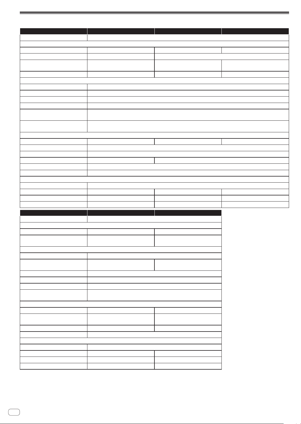
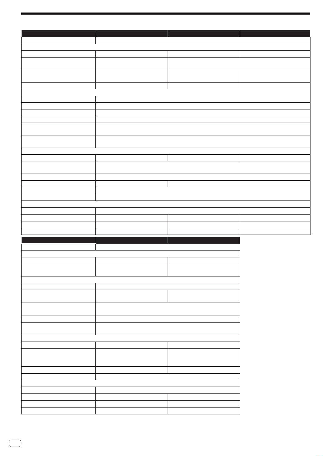
Specifications
XXPRS10 XPRS12 XPRS15
Type Bi-Amplifier 2-Way Active Full Range Speaker
System characteristic
Frequency Response (–10 dB) 55 Hz to 20 kHz 50 Hz to 20 kHz 40 Hz to 20 kHz
Directional characteristic (H x V) 90° x 60° 90° x 60° (90 degree rotatable)
Maximum Sound Pressure Level
(peak@1 m)*
Crossover Frequency 2.0 kHz 2.0 kHz 2.0 kHz
Amplifier
Amplifier type Class D
Amplifier output 1 200 W (LF800 W/HF400 W) peak 2 400 W
Input connectors XLR/TRS Combo x 2 (balanced) RCA x 2 (unbalanced)
Impedance 10kΩ
Output connectors Through output XLR x 2 (balanced)
Indicator (Front Panel Facilities) FRONT LED
Speaker
Woofer (LF) 10-inch cone 12-inch cone 15-inch cone
Tweeter (HF) 1-inch throat 1.75-inch diaphragm compression driver
Enclosure 15 mm birch plywood bass reflex type
Handle 1 (top) 2 (on both sides)
Pole socket 35 mm socket (0°/7° multi-angle)
Rigging point M10 x 12
Power unit/other
Supported voltages 100 V (50 Hz/60 Hz) / 110 V to 240 V (50 Hz/60 Hz)
Power consumption 162 W 167 W 175 W
External dimensions W x H x D 320 mm x 520 mm x 374 mm 380 mm x 647 mm x 398 mm 445 mm x 750 mm x 416 mm
Weight 18.9 kg 23.1 kg 29.2 kg
Type Active Subwoofer
System characteristic
Frequency Response (–10 dB) 40 Hz to 160 Hz 40 Hz to 160 Hz
Maximum Sound Pressure Level
(peak@1 m)*
Amplifier
Amplifier type Class D
Amplifier output 1 200 W
Input connectors XLR/TRS Combo x 2 (balanced)
Impedance 10kΩ
Output connectors Through output XLR x 2 (balanced)
Indicator (Front Panel Facilities) FRONT LED
Speaker
Woofer (LF) 15-inch cone 15-inch cone×2
Enclosure 15 mm birch plywood bass reflex
Handle 2 (on both sides) 4 (on both sides)
Pole socket M20 screw socket
Power unit/other
Supported voltages 100 V (50 Hz/60 Hz) / 110 V to 240 V (50 Hz/60 Hz)
Power consumption 240 W 240 W
External dimensions W x H x D 480 mm x 476 mm x 633 mm 743 mm x 524 mm x 811 mm
Weight 30.6 kg 55.9 kg
* Calculated value
Specifications and design are subject to possible modification without notice, due to improvements.
134 dB 135 dB 136 dB
Mixed output XLR x 1 (balanced)
(Rear Panel Facilities) POWER LIMIT SIGNAL x 2
XXPRS115S XPRS215S
133 dB (half space) 135 dB (half space)
peak 2 400 W
(Rear Panel Facilities) POWER LIMIT SIGNAL x 2
type
1 200 W (600 W x 2)
peak 2 400 W
15 mm birch plywood quasi
band pass type
10
En
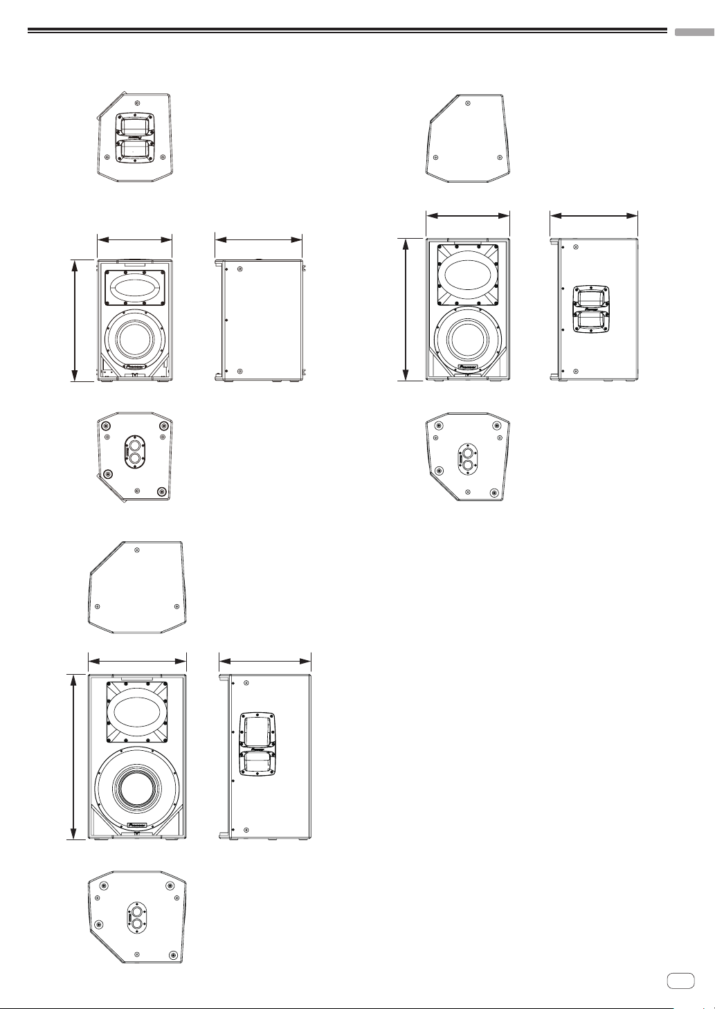
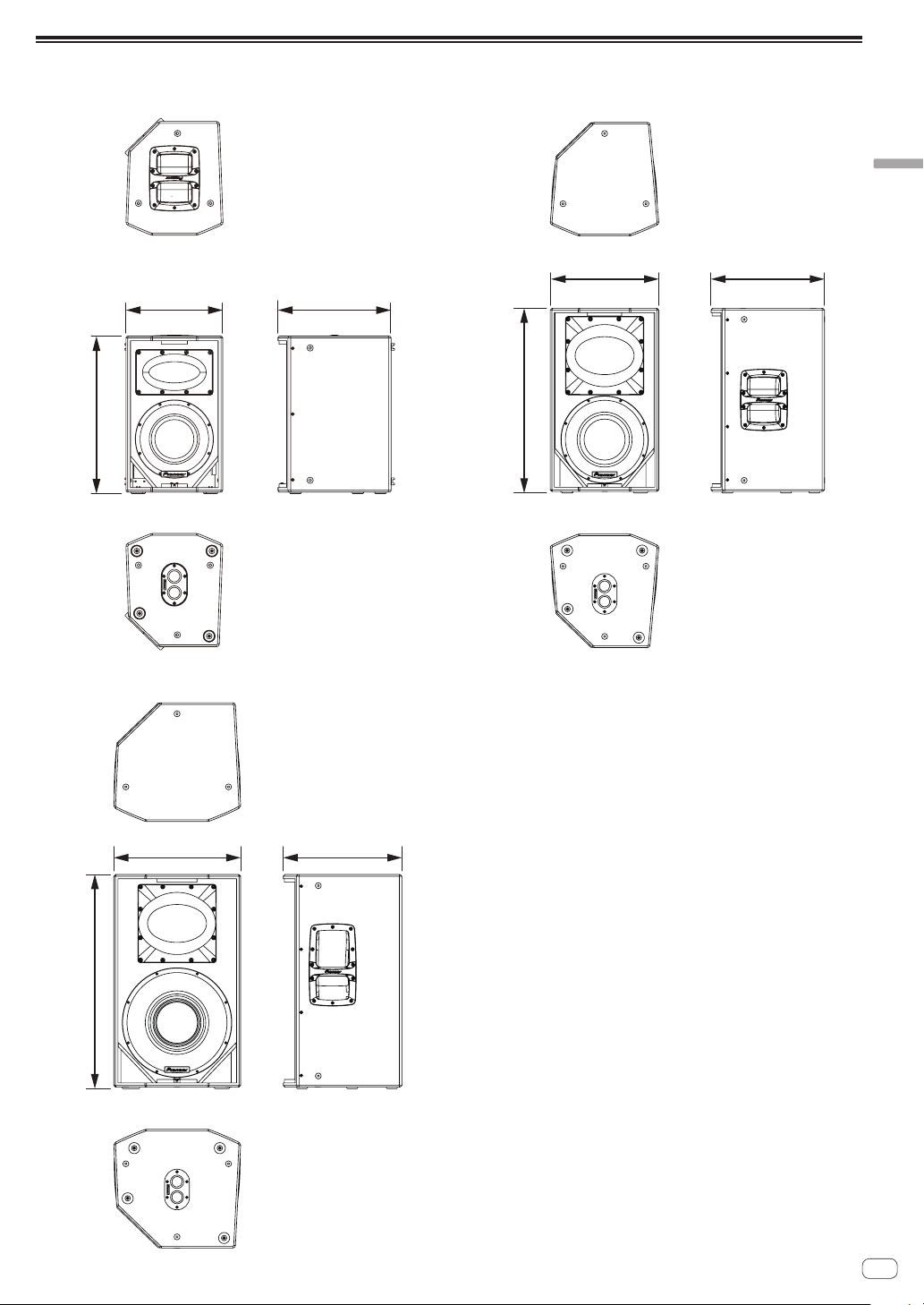
Dimensions
520 mm
Upper cross-section
647 mm
Upper cross-section
750 mm
Upper cross-section
XPRS10
English
XPRS12
398 mm380 mm
374 mm320 mm
Lower cross-section
XPRS15
Lower cross-section
416 mm445 mm
Lower cross-section
En
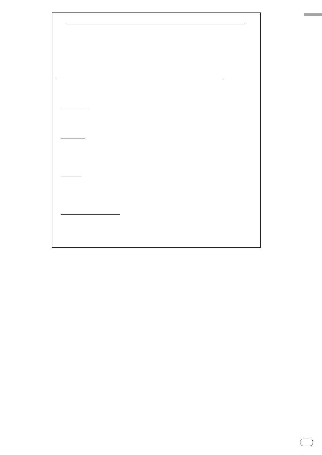
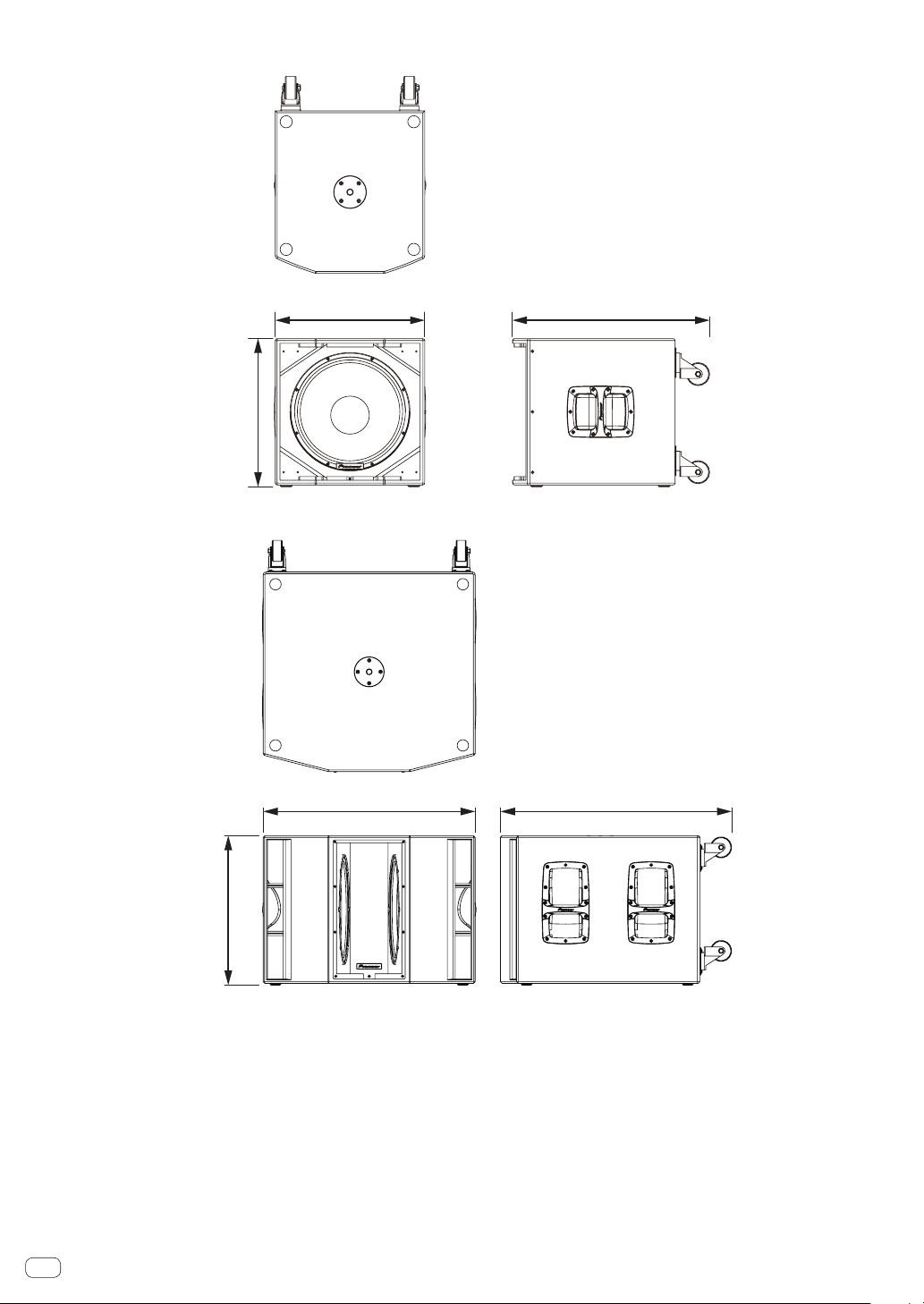
11

XPRS115S
476 mm
Upper cross-section
Upper cross-section
524 mm
XPRS215S
633 mm480 mm
12
En
743 mm
811 mm
AFTER-SALES SERVICE FOR Pioneer DJ PRODUCTS
Please contact the dealer or distributor from where you purchased the
product for its after-sales service (including warranty conditions) or any
other information. In case the necessary information is not available,
please contact the Pioneer’s subsidiaries (regional service headquarters)
listed below:
PLEASE DO NOT SHIP YOUR PRODUCT TO THE COMPANIES at the
addresses listed below for repair without advance contact, for these
companies are not repair locations.
AMERICA
PIONEER ELECTRONICS (USA) INC.
P. O. BOX 1760, LONG BEACH, CA 90801-1760, U.S.A.
EUROPE
PIONEER EUROPE NV
EUROPEAN SERVICE DIVISION
HAVEN 1087, KEETBERGLAAN 1, B-9120 MELSELE, BELGIUM
ASEAN
PIONEER ELECTRONICS ASIACENTRE PTE. LTD.
SERVICE DEPARTMENT
2 JALAN KILANG BARAT, #07-01, SINGAPORE 159346
English
JAPAN AND OTHERS
PIONEER SERVICE NETWORK
SUMITOMO FUDOSAN NISHISHINJUKU BUILDING 6F, 4-15-3
NISHISHINJUKU, SHINJUKU-KU, TOKYO 160-0023, JAPAN
S016_PDJ_A1_En
En
13
UCP0516
Pioneer DJ Americas, Inc.
WARRANTY VALID ONLY IN THE U.S.A. AND CANADA
WARRANTY
Pioneer DJ Americas, Inc. (PDJA) warrants that products distributed by PDJA in the U.S.A. and Canada that fail to function properly under normal use due to a manufacturing
defect when installed and operated according to the owner’s manual enclosed with the unit will be repaired or replaced with a unit of comparable value, at the option of PDJA,
without charge to you for parts or actual repair work. Parts supplied under this warranty may be new or rebuilt at the option of PDJA.
THIS LIMITED WARRANTY APPLIES TO THE ORIGINAL OR ANY SUBSEQUENT OWNER OF THIS PIONEER DJ PRODUCT DURING THE WARRANTY PERIOD PROVIDED THE
PRODUCT WAS PURCHASED FROM AN AUTHORIZED PIONEER DJ DISTRIBUTOR/DEALER IN THE U.S.A. OR CANADA. YO U WILL BE REQUIRED TO PROVIDE A SALES
RECEIPT OR OTHER VALID PROOF OF PURCHASE SHOWING THE DATE OF ORIGINAL PURCHASE OR, IF RENTED, YO UR RENTAL CONTRACT SHOWING THE PLACE AND
DATE OF FIRST RENTAL. IN THE EVENT SERVICE IS REQUIRED, THE PRODUCT MUST BE DELIVERED WITHIN THE WARRANTY PERIOD, TRANSPORTATION PREPAID,
ONLY FROM WITHIN THE U.S.A. AS EXPLAINED IN THIS DOCUMENT. YOU WILL BE RESPONSIBLE FOR REMOVAL AND INSTALLATION OF THE PRODUCT. PDJA WILL PAY
TO RETURN THE REPAIRED OR REPLACEMENT PRODUCT TO YOU WITHIN THE U.S.A.
PRODUCT WARRANTY PERIOD
Active Loudspeaker/Subwoofer : XPRS Series .......................................................................................................................................... 3 Year 3 Year
The warranty period for retail customers who rent the product commences upon the date product is first put into use (a) during the rental period or (b) retail sale, whichever occurs first.
WHAT IS NOT COVERED
IF THIS PRODUCT WAS PURCHASED FROM AN UNAUTHORIZED DISTRIBUTOR, THERE ARE NO WARRANTIES, EXPRESS OR IMPLIED, INCLUDING THE IMPLIED WARRANTY
OF MERCHANTABILITY AND THE IMPLIED WARRANTY OF FITNESS FOR A PA RTICULAR PURPOSE AND THIS PRODUCT IS SOLD STRICTLY “AS IS” AND “WITH ALL FAULTS".
PIONEER DJ SHALL NOT BE LIABLE FOR ANY CONSEQUENTIAL AND/OR INCIDENTAL DAMAGES.
THIS WARRANTY DOES NOT APPLY IF THE PRODUCT HAS BEEN SUBJECTED TO POWER IN EXCESS OF ITS PUBLISHED POWER RATING.
THIS WARRANTY DOES NOT COVER THE CABINET OR ANY APPEARANCE ITEM, USER ATTACHED ANTENNA, ANY DAMAGE TO RECORDS OR RECORDING TAPE
DAMAGE TO THE PRODUCT RESULTING FROM ALTERATIONS, MODIFICATIONS NOT AUTHORIZED IN WRITING BY PIONEER DJ, ACCIDENT, MISUSE OR ABUSE, DAMAGE DUE TO
LIGHTNING OR TO POWER SURGES, SUBSEQUENT DAMAGE FROM LEAKING, DAMAGE FROM INOPERATIVE BATTERIES, OR THE USE OF BATTERIES NOT CONFORMING TO THOSE
SPECIFIED IN THE OWNER’S MANUAL.
THIS WARRANTY DOES NOT COVER THE COST OF PARTS OR LABOR WHICH WOULD BE OTHERWISE PROVIDED WITHOUT CHARGE UNDER THIS WARRANTY OBTAINED FROM
ANY SOURCE OTHER THAN A PIONEER DJ AUTHORIZED SERVICE COMPANY OR OTHER DESIGNATED LOCATION. THIS WARRANTY DOES NOT COVER DEFECTS OR DAMAGE CAUSED
BY THE USE OF UNAUTHORIZED PA RTS OR LABOR OR FROM IMPROPER MAINTENANCE.
ALTERED, DEFACED, OR REMOVED SERIAL NUMBERS VOID THIS ENTIRE WARRANTY
NO OTHER WARRANTIES
PIONEER DJ LIMITS ITS OBLIGATIONS UNDER ANY IMPLIED WARRANTIES INCLUDING, BUT NOT LIMITED TO, THE IMPLIED WARRANTIES OF MERCHANTABILITY AND
FITNESS FOR A PARTICULAR PURPOSE, TO A PERIOD NOT TO EXCEED THE WARRANTY PERIOD. NO WARRANTIES SHALL APPLY AFTER THE WARRANTY PERIOD.
SOME STATES DO NOT ALLOW LIMITATIONS ON HOW LONG AN IMPLIED WARRANTY LASTS AND SOME STATES DO NOT ALLOW THE EXCLUSIONS OR LIMITATIONS
OF INCIDENTAL OR CONSEQUENTIAL DAMAGES, SO THE ABOVE LIMITATIONS OR EXCLUSIONS MAY NOT APPLY TO YO U. THIS WARRANTY GIVES YOU SPECIFIC LEGAL
RIGHTS AND YOU MAY HAVE OTHER RIGHTS WHICH MAY VARY FROM STATE TO STATE.
TO OBTAIN SERVICE
PDJA has appointed a number of Authorized Service Companies throughout the U.S.A. and Canada should your product require service. To receive warranty service you
need to present your sales receipt or, if rented, your rental contract showing place and date of original owner’s transaction. If shipping the unit you will need to package it
carefully and send it, transportation prepaid by a traceable, insured method, to an Authorized Service Company. Package the product using adequate padding material to
prevent damage in transit. The original container is ideal for this purpose. Include your name, address and telephone number where you can be reached during business
hours.
On all complaints and concerns in the U.S.A. and Canada call Customer Support at 1-800-872-4159.
LIMITED WARRANTY
PartsLabor
S OR DISCS, ANY
For hook-up and operation of your unit or to locate an
Authorized Service Company, please call or write:
DISPUTE RESOLUTION
Following our response to any initial request to Customer Support, should a dispute arise between you and Pioneer DJ, Pioneer DJ makes available its Complaint Resolution
Program to resolve the dispute. The Complaint Resolution Program is available to you without charge. Yo u are required to use the Complaint Resolution Program before you exercise
any rights under, or seek any remedies, created by Title I of the Magnuson-Moss Warranty-Federal Tr ade Commission Improvement Act, 15 U.S.C. 2301 et seq.
To use the Complaint Resolution Program call 1-800-872-4159 and explain to the customer service representative the problem you are experiencing, steps you have taken
to have the product repaired during the warranty period and the name of the authorized Distributor/Dealer from whom the Pioneer DJ product was purchased. After the
complaint has been explained to the representative, a resolution number will be issued. Within 40 days of receiving your complaint, Pioneer DJ will investigate the dispute
and will either: (1) respond to your complaint in writing informing you what action Pioneer DJ will take, and in what time period, to resolve the dispute; or (2) respond to your
complaint in writing informing you why it will not take any action.
CUSTOMER SUPPORT
PIONEER ELECTRONICS (USA) INC.
LONG BEACH, CALIFORNIA 90801
P.O. BOX 1720
1-800-872-4159
http://www.pioneerelectronics.com
RECORD THE PLACE AND DATE OF PURCHASE FOR FUTURE REFERENCE
Model No. ____________________________________________ Serial No. _________________________________________ Purchase Date ______________________
Purchased From ____________________________________________________________________________________________________________________________
KEEP THIS INFORMATION AND YOUR SALES RECEIPT IN A SAFE PLACE
_
14
En

English
En
15

Introduction
XPRS215S
4
1
2
3
Modèle large bande à 2 voies
XPRS10, XPRS12, XPRS15
4
3
XPRS115S
Comment lire ce document
Merci d’avoir acheté un produit Pioneer DJ. Afin de maximiser les fonctions de cet appareil et de les utiliser efficacement, veuillez lire
attentivement ce mode d’emploi et les consignes de sécurité importantes pour une utilisation correcte.
Veillez particulièrement à lire les consignes de sécurité importantes et à conserver le mode d’emploi et les consignes de sécurité
importantes avec la garantie.
Pour plus d’informations sur l’installation, veuillez lire le manuel d’installation.
http://pioneerproaudio.com
Caractéristiques principales
Une sortie élevée de 2 400 W et une qualité acoustique
supérieure sont obtenues en montant un module d’amplification
de Classe D du leader du secteur, Powersoft, dans un coffret en
bois offrant des caractéristiques acoustiques exceptionnelles.
Le XPRS peut non seulement être utilisé en tant que système
fixe dans un organe fixe, mais également en tant qu’équipement
de sonorisation lors d’événements où il peut facilement être
transporté et rapidement configuré.
Design de qualité acoustique supérieure d’un coffret en
g
bois offrant des caractéristiques acoustiques exceptionnelles
Un coffret en bois est utilisé pour proposer une qualité
acoustique supérieure sur tous les modèles.
Le coffret fabriqué en matériaux ultra-résistants offre des
caractéristiques acoustiques exceptionnelles et reproduit une
qualité acoustique nette, qu’il s’agisse d’un son faible ou puissant.
Equipé d’un module d’amplification de Classe D très
g
efficace et ultra-puissant
Le XPRS est équipé d’un module d’amplification de Classe D
développé sur la technologie de Powersoft et permet d’obtenir
une sortie élevée de 2 400 W (en crête) comparable à celle d’un
amplificateur à puissance élevée.
L’exceptionnel rendement énergétique permet de réduire
l’énergie nécessaire pour obtenir la même puissance de sortie.
Fonctions de protection avancées empêchant les
g
problèmes sur le terrain
Différentes fonctions, comme le suivi de l’état et le limiteur,
protègent efficacement le circuit, l’amplificateur et le bloc
d’alimentation grâce à une commande DSP avancée. Les
circuits de protection conçus pour répondre aux exigences de
fiabilité professionnelle empêchent les problèmes sur le terrain.
Différentes prises d’E/S permettant des connexions système flexibles
g
Une fonction de mixage, qui associe différentes sources d’entrée
et les transmet, est disponible. Une prise de sortie traversante
est également prévue pour simplifier la connexion à des hautparleurs large bande et plusieurs caissons de basses.
Quatre modes EQ permettant de configurer rapidement
g
le système (modèles large bande)
Quatre modes d’égalisation (FLAT, BASS+, SPEECH et WEDGE)
permettant de sélectionner la caractéristique acoustique la
mieux adaptée à une application sont accessibles via la sélection
d’un simple commutateur.
Douille à pôles multi-angle permettant d’installer un
g
pôle à deux angles (modèles large bande)
Deux angles de 0 et 7° peuvent être choisis pour s’adapter à l’événement
lors de l’installation des haut-parleurs à l’aide d’un pôle.
Configurez la présence de tous les accessoires
Cordons d’alimentation
Manuel d’installation et d’utilisation (ce document)
Consignes de sécurité importantes
Le contenu de la garantie pour les États-Unis et le Canada est fourni aux
dernières pages des instructions en anglais et en français.
Noms et fonctions des organes
Organes du panneau avant
Tweeter
1
Circuit de compression du diaphragme de 1,75 pouce, gorge de 1 pouce
Klaxon rotatif (XPRS12, XPRS15)
2
Il s’agit d’un klaxon à directivité constante qui peut être tourné.
• Directivitéd’usinepardéfaut:90degréshorizontalementet60
degrés verticalement
• Directivitésitournéde90degrés:60degréshorizontalementet
90 degrés verticalement
Klaxon (XPRS10)
2
Il s’agit d’un klaxon à directivité constante avec une directivité de 90
degrés horizontalement et de 60 degrés verticalement.
* La rotation du klaxon n’est pas possible pour XPRS10.
Caisson
3
Voyant FRONT LED
4
Il s’agit d’un voyant LED blanc. Son éclairage dépend du réglage
FRONT LED sur le panneau arrière. Pour en savoir plus sur les
réglages, reportez-vous à l’explication du panneau arrière.
3
Fr
2
Modèle de caisson de basses
Modèle de caisson de basses
4

Organes du panneau arrière (modèles large bande)
3
4
b
a
9
c
e
d
g
f
7
5
6
7
8
Français
1
2
Interrupteur POWER
1
Allume et éteint ce haut-parleur.
AC IN
2
Branchez le cordon d’alimentation à AC IN et à la prise électrique.
Porte-fusibles
3
Voyant d’alimentation
4
S’allume en bleu lors de la mise sous tension.
MASTER LEVEL
5
Ajuste le niveau de sortie.
EQ MODE SELECT
6
Bascule entre quatre modes EQ (FLAT, BASS+, SPEECH et WEDGE).
Pour plus de détails, voir « Réglages EQ MODE » à la page 6.
Bouton INPUT LEVEL
7
Ajuste le niveau du signal d’entrée.
Bouton GAIN (pour MIC/LINE1 uniquement)
8
Sélectionnez le gain en fonction du niveau du signal de sortie du
dispositif à raccorder. Le gain sélectionné est ajouté au signal
transmis à cet appareil.
• Pour transmettre le signal d’un dispositif à sortie de ligne à
ce haut-parleur, sélectionnez [0 dB] ou [12 dB].
• Pour transmettre un signal de sortie de bas niveau tel que
celui d’un microphone à cet appareil, sélectionnez [24 dB]
ou [36 dB].
Voyant SIGNAL
9
Un voyant vert s’allume lorsqu’un signal d’entrée est détecté.
MIC/LINE1 et LINE2 INPUT
a
Les connecteurs XLR (symétrique) et TRS 1/4” TRS (type
symétrique PHONO) sont pris en charge. Le connecteur XLR
comprend 1 « masse », 2 « en circuit » et 3 « hors circuit ».
LINK
b
Il s’agit du connecteur de sortie XLR (symétrique). Un signal
transmis à XLR INPUT est directement émis. (Un signal transmis
à AUX IN de LINE2 n’est pas émis.)
9
a
b
Voyant LIMIT
c
S’allume en rouge lorsque le limiteur incorporé est activé
ou lorsque le niveau d’entrée est trop élevé et que le son est
déformé. Lorsque cela se produit, diminuez le niveau de sortie du
dispositif raccordé ou diminuez le niveau d’entrée ou le niveau
principal de cet appareil.
EXT SUB MODE
d
Sélectionnez [ ] pour une utilisation normale.
Sélectionnez [ ] lors de l’utilisation d’un haut-parleur
d’extrêmes graves.
FRONT LED
e
Sélectionne le réglage d’affichage du voyant FRONT LED (blanc).
[POWER] S’allume lors de la mise sous tension.
[LIMIT] S’allume lorsque le limiteur est activé.
[OFF] Le voyant FRONT LED ne s’allume pas.
AUX IN
f
Il s’agit des connecteurs d’entrée RCA (asymétriques).
Une entrée de signal stéréo vers AUX IN est mixée à un signal
monaural (non émis par le connecteur LINK).
MIX OUT
g
Il s’agit du connecteur de sortie XLR (symétrique). Mixe le signal
transmis à MIC/LINE1 et Line2, puis l’émet.
Un signal ajusté dans MIC GAIN et INPUT LEVEL est transmis.
ATTENTION
Lorsque le réglage FRONT LED est réglé sur [OFF] et [LIMIT],
le haut-parleur peut sembler identique à ce qu’il est lorsque la
prise d’alimentation est débranchée de la prise électrique en
fonction de la spécification du produit, mais l’alimentation n’est
pas coupée. Si vous souhaitez couper totalement l’alimentation
du caisson, vous devez débrancher la prise d’alimentation de
la prise électrique. Installez le haut-parleur à proximité d’une
prise électrique afin que la prise d’alimentation soit facilement
accessible. Le fait de laisser la prise d’alimentation insérée
dans une prise électrique pendant une période prolongée peut
provoquer un incendie.
Fr
3

Organes du panneau arrière (Modèle de caisson de basses)
3
4
a
c
b
9
8
7
5
6
7
8
1
2
9
Interrupteur POWER
1
Allume et éteint ce haut-parleur.
AC IN
2
Branchez le cordon d’alimentation à AC IN et à la prise électrique.
Porte-fusibles
3
Power indicator
4
S’allume en bleu lors de la mise sous tension.
MASTER LEVEL
5
Ajuste le niveau de sortie.
CROSS OVER
6
Sélectionne la fréquence de coupure du filtre passe-bas du
caisson de basses entre 80 Hz, 100 Hz, 120 Hz et 150 Hz.
Une fréquence de coupure de 100 Hz est recommandée lors de
l’utilisation du haut-parleur d’extrêmes graves avec les haut-parleurs
pleine gamme de la série XPRS.
Voyant SIGNAL
7
Un voyant vert s’allume lorsqu’un signal d’entrée est détecté.
LINE1 et LINE2 INPUT
8
Les connecteurs XLR (symétrique) et TRS 1/4” TRS (type
symétrique PHONO) sont pris en charge. Le connecteur XLR
comprend 1 « masse », 2 « en circuit » et 3 « hors circuit ».
LINK
9
Il s’agit du connecteur de sortie XLR (symétrique). Une entrée de
signal vers XLR INPUT est transmise directement.
Voyant LIMIT
a
S’allume en rouge lorsque le limiteur incorporé est activé
ou lorsque le niveau d’entrée est trop élevé et que le son est
déformé. Dans ce cas, réduisez le niveau de sortie de l’appareil
connecté ou réduisez le niveau d’entrée ou le niveau principal de
cette unité.
PHASE
b
Change la polarité du caisson de basses. Sélectionnez celle qui
améliore la lecture des basses fréquences lors de l’utilisation du
haut-parleur d’extrêmes graves avec d’autres haut-parleurs.
FRONT LED
c
Sélectionne le réglage d’affichage du voyant FRONT LED (blanc).
[POWER] S’allume lors de la mise sous tension.
[LIMIT] S’allume lorsque le limiteur est activé.
[OFF] Le voyant FRONT LED ne s’allume pas.
ATTENTION
Lorsque le réglage FRONT LED est défini sur [OFF] et [LIMIT],
le haut-parleur peut être le même que lorsque la fiche
d’alimentation est débranchée de la prise secteur selon
les spécifications du produit, mais l’alimentation n’est pas
coupée. Si vous souhaitez couper totalement l’alimentation
du caisson, vous devez débrancher la prise d’alimentation de
la prise électrique. Installez le haut-parleur à proximité d’une
prise électrique afin que la prise d’alimentation soit facilement
accessible. Le fait de laisser la prise d’alimentation insérée
dans une prise électrique pendant une période prolongée peut
provoquer un incendie.
Fr
4
Installation et raccordements
Douille à pôles multi-angle
Installation avec un pôle de haut-parleur
XPRS215S
Comment installer
Le son de lecture du haut-parleur est légèrement affecté par les conditions de
la pièce d’écoute. Prenez rigoureusement en compte le site d’installation avant
d’installer le haut-parleur afin qu’il puisse être utilisé de manière optimale.
Pioneer DJ ne sera pas tenu pour responsable de tout dommage résultant
de l’utilisation du haut-parleur (notamment, mais sans s’y limiter, la perte
d’opportunités commerciales), quelle que soit la méthode d’installation.
Utilisez les poignées illustrées à droite lors du déplacement et de l’installation
du haut-parleur.
Utilisez les poignées en haut ou sur les côtés du haut-parleur lors du
déplacement et de l’installation du haut-parleur.
Installation avec un pôle de haut-parleur
XPRS12/XPRS15
Les modèles large bande de la série XPRS comportent une douille à pôles
multi-angle de 35 mm de diamètre sur la partie inférieure et peuvent être
installés vers le bas à un angle de 0° ou 7° par rapport au sol.
Le modèle de caisson de basses de la série XPRS comportent une douille à
pôles à vis M20 sur la partie supérieure et le pôle peut être fermement fixé.
Les combinaisons illustrées dans les figures suivantes sont
recommandées pour la série XPRS. L’utilisation d’une autre combinaison
peut entraîner un basculement des haut-parleurs, provoquant ainsi
des dommages ou des blessures. Pour utiliser un pôle de haut-parleur,
consultez les précautions à droite et effectuez une installation sécurisée.
ATTENTION
Lorsque vous installez le XRS115S, XPRS215S, en position verticale ou
!
horizontale, veillez à ce que les roulettes ne glissent pas et n’entraînent pas
de blessure.
Pour permettre un meilleur refroidissement, veillez à ce qu’un espace
!
suffisant soit laissé entre les haut-parleurs et les murs ou autres
composants à proximité (30 cm minimum au-dessus, derrière et sur les
côtés droit et gauche de chaque haut-parleur). Le fait de ne pas laisser
d’espace suffisant entre le haut-parleur et les murs ou d’autres composants
peut entraîner une augmentation des températures intérieures et provoquer
un dysfonctionnement ou des dommages.
ATTENTION
• Aumoinsdeuxpersonnesdoiventsouleverlehaut-parleurpour
l’installer. Prenez en compte l’aspect sécurité pendant l’opération.
• Pourlepôledehaut-parleur,utilisezunpôledehaut-parleuràvisM20
sur un côté de 35 mm de diamètre. Utilisez un produit disponible dans
le commerce de 900 mm de longueur maximum. Pioneer DJ ne sera
pas tenu pour responsable de tout dommage (notamment, mais s’y
limiter, la perte d’opportunités commerciales) résultant de l’utilisation
d’un pôle de haut-parleur autre que celui spécifié.
• Installezlecaissondebassesdansunendroitstableetfixez
fermement le pôle de haut-parleur.
• Vérifiezl’absencederisquedebasculementduhaut-parleur.
• Lescâblesdoiventêtreattachésouliésàl’aided’attache-câblespour
éviter le risque de trébuchement sur les câbles et de basculement du
haut-parleur.
Français
Face avant
7° 0°
Raccord pour tube de
liaison de 35 mm de
diamètre
Raccord pour
tube de liaison
avec filetage M20
Face avant
XPRS12, XPRS15
7°
0°
Fr
5
Installation avec les points de fixation sur le haut-parleur
:Points de fixation
:Roulette :Vis hexagonale M5
Les modèles large bande comportent des points de fixation de montage
!
suspendu. Le haut-parleur peut être suspendu à l’aide de boulons à œil
disponibles dans le commerce. Le point de fixation est doté d’un trou de vis
M10 (pour un boulon à œil d’une longueur de filetage de 30 mm à 50 mm).
Lors de l’installation du haut-parleur suspendu, demandez à un
!
technicien qualifié de procéder à l’opération.
Retirez les vis des points de fixation sur le haut-parleur et fixez les
!
boulons à œil. N’utilisez pas le haut-parleur lorsque les vis sont
retirées. Les fuites d’air auraient une incidence négative sur le son.
Veillez à utiliser au moins trois points de fixation pour suspendre le
!
haut-parleur. De plus, assurez-vous également de prendre une mesure
de sécurité supplémentaire telle que l’utilisation d’un fil.
Utilisez des crochets, fils et un mur ou un plafond suffisamment résistant pour
!
supporter le poids du haut-parleur. Dans le magasin où vous avez acheté le
haut-parleur, demandez des crochets disponibles dans le commerce.
Assurez-vous de la sécurité après l’installation du haut-parleur et
!
régulièrement par la suite.
Roulettes du modèle de caisson de graves
Le modèle de caisson de graves est fourni avec des roulettes qui vous permettent de le déplacer facilement.
!
Pour l’utiliser dans une installation fixe, vous pouvez retirer les roulettes.
!
Lorsque vous l’utilisez avec les roulettes retirées, veillez à remettre en place les vis de fixation des roulettes.
!
Si vous l’utilisez avec les vis retirées, la qualité du son sera affectée par des fuites d’air.
(longueur de filetage de 25 mm)
Réglages EQ MODE
Quatre modes EQ (FLAT, BASS+, SPEECH et WEDGE) sont disponibles pour les modèles large bande. Le mode EQ peut être sélectionné
entre quatre options à l’aide du commutateur [EQ MODE SELECT]. Sélectionnez le mode le mieux adapté à vos préférences et à vos conditions
d’utilisation.
FLAT
Reproduit fidèlement le son entrant. (Réglage d’usine par défaut)
BASS+
Ce réglage augmente la présence de basses fréquences et reproduit les sons puissants de dance music dans une discothèque, etc.
SPEECH
Ce réglage accentue les fréquences vocales afin de faciliter l’écoute de la voix d’un conférencier, etc.
WEDGE
Ce réglage supprime l’amplification excessive des basses fréquences qui se produit lorsque le haut-parleur est installé sur le sol en
tant que retour de scène.
Raccordements
Lorsque vous effectuez ou modifiez des raccordements, coupez toujours l’alimentation et débranchez le cordon d’alimentation de sa prise.
Veillez également à bien lire les instructions d’utilisation des autres composants auxquels vous connectez ces haut-parleurs.
Ne branchez le cordon d’alimentation que lorsque tous les autres raccordements sont terminés.
N’utilisez que le cordon d’alimentation fourni en accessoire.
Fr
6
Exemple de configuration
Table de mixage DJ, etc.
Système stéréo général
Raccordement d’un amplificateur
0 dB
Table de mixage DJ, etc.
Système avec un microphone raccordé seulement
Il est recommandé de régler EQ MODE SELECT sur SPEECH.
Raccordement d’un amplificateur
Mode EQ :
SPEECH
Sélection du GAIN
Remarque:
Pour empêcher le hurlement de retour
Utilisez le microphone avec sa directivité hors ligne par rapport au
!
sens de sortie du haut-parleur. Par exemple, utilisez le microphone
derrière le haut-parleur, ou modifiez le sens du microphone.
Utilisez le microphone avec le réglage GAIN et le bouton INPUT LEVEL
!
dans les positions appropriées.
Français
Système de retour sur scène
Le réglage de EQ MODE SELECT sur WEDGE est recommandé.
Raccordement d’un amplificateur
Table de mixage DJ, etc.
Fr
7
Système avec caisson de basses raccordé
XPRS12 ou XPRS15 XPRS12 ou XPRS15
Table de mixage DJ, etc.
Table de mixage DJ, etc.
Raccordement d’un amplificateur
Table de mixage DJ, etc.
XPRS215S XPRS215S
Lorsque vous utilisez le haut-parleur avec la série XPRS, il est
recommandé de régler EXT SUB MODE d’un modèle large bande sur
] et de régler CROSS OVER du modèle de caisson de basses sur
[
100 Hz.
Système avec XPRS215S Mono Mix raccordé
Raccordement d’un amplificateur
XPRS12 XPRS12
Table de mixage DJ, etc.
XPRS215S
Fr
8

Informations supplémentaires
En cas de panne
Si vous pensez rencontrer un dysfonctionnement avec cette unité, vérifiez les éléments suivants. Vérifiez également les autres appareils connectés à
!
l’unité. Si le problème persiste, contactez votre revendeur.
On occasion, the unit may fail to operate properly due to static electricity or other external conditions. In this event, disconnect the power cord and
!
wait for five seconds or more, then reconnect the power cord and check for proper operation.
Symptôme Eléments à vérifier Solution
Pas d’alimentation Le cordon d’alimentation est-il branché
Aucun son des appareils audio
connectés, ou le son est très
faible.
Le son est déformé, ou le voyant
LIMIT est allumé.
Hurlement (effet de retour) Le microphone est orienté vers le
correctement ?
L’appareil audio connecté est-il réglé
correctement ?
Le câble de raccordement est-il branché
correctement ?
Est-ce que les connecteurs ou les fiches sont
sales ?
Le niveau acoustique est-il réglé correctement ? Tournez lentement le bouton MASTER LEVEL sur
L’alimentation est-elle sur ON ? Tournez l’interrupteur POWER sur le panneau
Le sélecteur de GAIN est-il correctement
réglé ?
Le volume est-il réglé sur la bonne position ? Tournez la commande MASTER LEVEL ou
Le niveau du signal de sortie de l’équipement
raccordé est-il correctement réglé ?
Le signal de sortie de l’équipement raccordé
est-il déformé ?
haut-parleur.
Le microphone et le haut-parleur sont-ils trop
proches l’un de l’autre ?
Le réglage du volume est-il dans la bonne
position ?
Branchez le cordon d’alimentation à une prise
(page 6).
Réglez le sélecteur de sortie de l’appareil et le
volume sonore de manière appropriée.
Branchez les câbles de manière appropriée
(page 7).
Nettoyez les connecteurs et les fiches avant de
raccorder.
le panneau arrière du haut-parleur vers la droite
pour augmenter le volume.
arrière du haut-parleur.
Vérifiez que le réglage de GAIN sur le panneau
arrière est correct (page 3).
INPUT LEVEL sur le panneau arrière dans le
sens inverse des aiguilles d’une montre pour
diminuer le volume jusqu’à ce que l’indicateur
LIMIT s’éteigne.
Ajustez le niveau de sortie de l’équipement
raccordé.
Consultez le mode d’emploi de l’équipement
raccordé.
Changez l’orientation du microphone.
Éloignez le microphone du haut-parleur.
Tournez la commande MASTER LEVEL ou INPUT
LEVEL dans le sens inverse des aiguilles d’une
montre pour diminuer le volume.
Français
Fr
9
Spécifications
XPRS10 XPRS12 XPRS15
Type Haut-parleur large bande actif 2 voies et bi-amplification
Caractéristiques du système
Réponse en fréquence (–10 dB) 55 Hz à 20 kHz 50 Hz à 20 kHz 40 Hz à 20 kHz
Caractéristique directionnelle
(H x V)
Niveau de pression acoustique
maximal (crête à 1 m)*
Fréquence de recouvrement 2,0 kHz 2,0 kHz 2,0 kHz
Amplificateur
Type d’amplificateur Classe D
Sortie d’amplification 1 200 W (LF 800 W/HF 400 W) crête 2 400 W
Connecteurs d’entrée XLR/TRS combinés x 2 (symétriques) RCA x 2 (asymétriques)
Impédance 10kΩ
Connecteurs de sortie Sortie traversante XLR x 2 (symétriques)
Voyant (Organes du panneau avant) FRONT LED
Haut-parleur
Caisson (LF) Cône de 10 pouces Cône de 12 pouces Cône de 15 pouces
Tweeter (HF) Circuit de compression du diaphragme de 1,75 pouce,
Coffret Type basse réflex en contreplaqué de bouleau de 15 mm
Poignée 1 (haut) 2 (des deux côtés)
Douille à pôles Douille de 35 mm (multi-angle 0°/7°)
Point de fixation M10 x 12
Bloc d’alimentation/autres
Tensions acceptées 100 V (50 Hz/60 Hz) / 110 V à 240 V (50 Hz/60 Hz)
Consommation électrique 162 W 167 W 175 W
Dimensions extérieures (l x H x P) 320 mm x 520 mm x 374 mm 380 mm x 647 mm x 398 mm 445 mm x 750 mm x 416 mm
Poids 18,9 kg 23,1 kg 29,2 kg
Type Caisson de basses actif
Caractéristiques du système
Réponse en fréquence (–10 dB) 40 Hz à 160 Hz 40 Hz à 160 Hz
Niveau de pression acoustique
maximal (crête à 1 m)*
Amplificateur
Type d’amplificateur Classe D
Sortie d’amplification 1 200 W
Connecteurs d’entrée XLR/TRS combinés x 2 (symétriques)
Impédance 10kΩ
Connecteurs de sortie Sortie traversante XLR x 2 (symétrique)
Voyant (Organes du panneau avant) FRONT LED
Haut-parleur
Caisson (LF) Cône de 15 pouces Cône de 15 pouces x 2
Coffret Type basse réflex en
contreplaqué de bouleau de 15
Poignée 2 (des deux côtés) 4 (des deux côtés)
Douille à pôles Douille à vis M20
Bloc d’alimentation/autres
Tensions acceptées 100 V (50 Hz/60 Hz) / 110 V à 240 V (50 Hz/60 Hz)
Consommation électrique 240 W 240 W
Dimensions extérieures (l x H x P) 480 mm x 476 mm x 633 mm 743 mm x 524 mm x 811 mm
Poids 30,6 kg 55,9 kg
* Valeur calculée
Spécifications et design sous réserve de modifications sans préavis en raison d’améliorations éventuelles.
90° x 60° 90° x 60° (pivotant sur 90 degrés)
134 dB 135 dB 136 dB
Sortie mixée XLR x 1 (symétrique)
(Organes du panneau arrière) POWER LIMIT SIGNAL x 2
gorge de 1 pouce
XPRS115S XPRS215S
133 dB (demi-espace) 135 dB (demi-espace)
Crête 2 400 W
(Organes du panneau arrière) POWER LIMIT SIGNAL x 2
mm
1 200 W (600 W x 2)
Crête 2 400 W
Type quasi passe-bas en
contreplaqué de bouleau de
15 mm
10
Fr
Dimensions
520 mm
Coupe transversale supérieure
647 mm
Coupe transversale supérieure
750 mm
Coupe transversale supérieure
XPRS10
XPRS12
Français
398 mm380 mm
374 mm320 mm
Coupe transversale inférieure
XPRS15
Coupe transversale inférieure
416 mm445 mm
Coupe transversale inférieure
Fr
11
XPRS115S
476 mm
Coupe transversale supérieure
Coupe transversale supérieure
524 mm
XPRS215S
633 mm480 mm
Fr
12
743 mm
811 mm
UCP0516
Pioneer DJ Americas, Inc.
GARANTIE
Pioneer DJ Americas, Inc.(PDJA) garantie que les produits distribués par PDJA aux États-Unis ou au Canada qui, bien qu’étant installés et utilisés conformément au Manuel de
l’utilisateur fourni avec le produit, ne fonctionneraient pas correctement dans le cadre d’une utilisation normale en raison d’un défaut de fabrication seront réparés ou remplacés
par un produit de valeur équivalente, au choix de PDJA, sans frais à votre charge pour les pièces et/ou la main d’œuvre de réparation. Les pièces incluses en vertu de la présente
garantie peuvent être neuves ou remises à neuf, au choix de PDJA.
LA PRÉSENTE GARANTIE LIMITÉE S’APPLIQUE AU PROPRIÉTAIRE ORIGINAL AINSI QU’À TOUT PROPRIÉTAIRE SUCCESSIF DE CE PRODUIT PIONEER DJ PENDANT LA
PÉRIODE DE GARANTIE À CONDITION QUE LE PRODUIT AIT ÉTÉ ACHETÉ AUPRÈS D’UN DISTRIBUTEUR/DÉTAILLANT PIONEER DJ AGRÉÉ AUX ÉTATS-UNIS OU AU CANADA.
VOUS DEVREZ FOURNIR UN RELEVÉ DE CAISSE OU UNE AUTRE PREUVE D’ACHAT VA LIDE INDIQUANT LA DATE DE L’ACHAT INITIAL OU, SI VOUS LOUEZ LE PRODUIT,
VOTRE CONTRAT DE LOCATION INDIQUANT L’ENDROIT ET LA DATE DE LA PREMIÈRE LOCATION. EN CAS DE BESOIN DE RÉPARATION, LE PRODUIT DOIT ÊTRE RENVOYÉ
ET LIVRÉ AU COURS DE LA PÉRIODE DE GARANTIE, FRAIS DE PORT PAYÉS ET UNIQUEMENT DEPUIS L’ INTÉRIEUR DES ÉTATS-UNIS. COMME EXPLIQUÉ DANS LE PRÉSENT
DOCUMENT. VOUS ÊTES RESPONSABLE DU DÉMONTAGE ET DE L’INSTALLATION DU PRODUIT. PDJA PREND À SA CHARGE LES FRAIS D’EXPÉDITION DU PRODUIT RÉPA RÉ
OU REMPLACÉ JUSQU’À VOT RE ADRESSE À L’ INTÉRIEUR DES ÉTATS-UNIS.
PÉRIODE DE GARANTIE DES PRODUITS
Haut-parleur Actif/Caisson De Basses : Série XPRS ........................................................................................................................ 3 an 3 an
La période de garantie pour les clients qui louent le produit commence le jour où le produit est utilisé pour la première fois (a) pendant la période de location ou (b) après la
vente au détail, selon ce qui se produit en premier.
ÉLÉMENTS NON COUVERTS PAR LA GARANTIE
UN PRODUIT ACHETÉ CHEZ UN DISTRIBUTEUR NON AUTO RISÉ N’EST COUVERT PAR AUCUNE GARANTIE EXPRESSE OU IMPLICITE, Y COMPRIS QUELQUE GARANTIE
IMPLICITE DE QUALITÉ MARCHANDE OU D’ADAPTATION À UN USAGE PARTICULIER QUE CE SOIT. DE PLUS, CE PRODUIT EST STRICTEMENT VENDU « TEL QUEL » ET
« AVEC TOUS SES DÉFAUTS ÉVENTUELS ».
Pioneer DJ NE PEUT PAS ÊTRE TENU RESPONSABLE DES DOMMAGES INDIRECTS ET/OU ACCESSOIRES ÉVENTUELS.
LA PRÉSENTE GARANTIE NE S’APPLIQUE PA S SI LE PRODUIT A ÉTÉ SOUMIS À UNE PUISSANCE NOMINALE EXCÉDANT LA PUISSANCE INDIQUÉE DANS LES
SPÉCIFICATIONS FOURNIES.
LA PRÉSENTE GARANTIE NE COUVRE PAS LE BOÎTIER OU LES ÉLÉMENTS ESTHÉTIQUES, LES ANTENNES INSTALLÉES PAR L’UTILISATEUR, LES DOMMAGES AUX DISQUES OU
AUX RUBANS OU DISQUES D’ENREGISTREMENT, LES DOMMAGES AU PRODUIT DÉCOULANT D’UNE RETOUCHE, D’UNE MODIFICATION NON AUTORISÉE PAR ÉCRIT PAR Pioneer
DJ, D’UN ACCIDENT, D’UN USAGE INAPPROPRIÉ OU D’UN USAGE ABUSIF, LES DOMMAGES PRODUITS PAR LA FOUDRE OU LA SURTENSION, LES DOMMAGES SUBSÉQUENTS
DÉCOULANT DE FUITES, LES DOMMAGES DÉCOULANT DE PILES DÉFECTUEUSES OU DE L’UTILISATION DE PILES NON CONFORMES À CELLES QUI SONT SPÉCIFIÉES DANS LE
MANUEL DE L’UTILISATEUR.
LA PRÉSENTE GARANTIE NE COUVRE PA S LE COÛT DES PIÈCES OU DE LA MAIN-D’OEUVRE QUI SERAIENT AUTREMENT OFFERTES SANS FRAIS EN VERTU DE LA
PRÉSENTE GARANTIE, SI ELLES SONT OBTENUES AUPRÈS D’UNE SOURCE AUTRE QU’UNE SOCIÉTÉ DE SERVICE OU AUTRE AUTORISÉE OU DÉSIGNÉE PAR Pioneer DJ.
LA PRÉSENTE GARANTIE NE COUVRE PAS LES DÉFECTUOSITÉS OU LES DOMMAGES CAUSÉS PAR L’UTILISATION D’UNE MAIN-D’OEUVRE OU DE PIÈCES NON AUTORISÉES, ET/
OU D’UN ENTRETIEN INADÉQUAT.
LES NUMÉROS DE SÉRIE MODIFIÉS, OBLITÉRÉS OU ENLEVÉS ANNULENT LA PRÉSENTE GARANTIE DANS SA TOTALITÉ.
EXCLUSION DE TOUTE AUTRE GARANTIE
Pioneer DJ LIMITE SES OBLIGATIONS EN VERTU DE TOUTE GARANTIE IMPLICITE QUE CE SOIT, Y COMPRIS ENTRE AUTRES LES GARANTIES IMPLICITES DE QUALITÉ
MARCHANDE OU D’ADAPTATION À UN USAGE PARTICULIER, À UNE PÉRIODE N’EXCÉDANT PAS LA PÉRIODE DE GARANTIE. AUCUNE GARANTIE NE S’APPLIQUE APRÈS LA
PÉRIODE DE GARANTIE. CERTAINS ÉTATS NE PERMETTENT PAS LA LIMITATION DE LA DURÉE D’UNE GARANTIE IMPLICITE, ET CERTAINS NE PERMETTENT PAS L’EXCLUSION
OU LA LIMITATION DES DOMMAGES CONSÉCUTIFS OU INDIRECTS. LES LIMITATIONS ET EXCLUSIONS ÉTABLIES CI-DESSUS PEUVENT DONC NE PAS S’APPLIQUER À VOUS.
LA PRÉSENTE GARANTIE VOUS DONNE DES DROITS LÉGAUX SPÉCIFIQUES. VOUS POUVEZ JOUIR D’AUTRES DROITS, QUI PEUVENT VARIER D’UN ÉTAT À L’ AUTRE.
SERVICE APRÈS-VENTE
PDJA a autorisé un certain nombre de sociétés de service après-vente agréées à travers les États-Unis et le Canada pour le cas où votre produit
aurait besoin d’être réparé. Pour profiter d’un tel s ervice en vertu de la garantie, vous devez présenter votre ticket de caisse ou, si vous louez
le produit, votre c ontrat de location indiquant l’endroit et la date de la transaction par le premier propriétaire. Si vous expédiez le produit, vous
devez l’emballer soigneusement et l’envoyer à une société de service autorisée, en port prépayé et selon une méthode de transport incluant un
suivi et une assurance. Emballez le produit au moyen de matériaux de rembourrage appropriés pour éviter tout dommage pendant le transport.
L’emballage d’origine est idéal pour cela. Indiquez votre nom, votre adresse et un numéro de téléphone où nous pouvons vous joindre pendant les heures de bureau.
Pour toute réclamation et/ou question à l’intérieur des États-Unis ou du Canada, appelez le Service Consommateurs au 1-800-872-4159.
GARANTIE VALABLE UNIQUEMENT AUX ÉTATS-UNIS ET AU CANADA
GARANTIE LIMITÉE
Pièces Main-d’oeuvre
Français
Pour toute question concernant la mise en service ou l’utilisation de votre produit,
ou pour trouver une société de service autorisée, appelez ou écrivez à :
RÉSOLUTION DES LITIGES
Si un litige se produit entre vous et Pioneer DJ après la réponse à une demande initiale faite au Service Consommateurs, vous pouvez avoir recours au Programme de résolution des
plaintes de Pioneer DJ pour résoudre le litige. Le Programme de résolution des plaintes vous est offert gratuitement. Vous de
avant de vous prévaloir de vos droits ou de chercher réparation en vertu du Titre I de la loi Magnuson-Moss Warranty-Federal Trade Commission Improvement Act, 15 U.S.C. 2301 et seq.
Pour utiliser le Programme de résolution des plaintes, appelez le 1-800-872-4159 et expliquez au représentant du Service Consommateurs
le problème que vous rencontrez ainsi que les démarches que vous avez effectuées pour faire réparer le produit pendant la période
de garantie, puis communiquez-lui le nom du distributeur /détaillant autorisé auprès duquel vous a vez acheté le produit P ioneer DJ.
Une fois que votre plainte a été expliquée au représentant, un numéro de résolution vous sera communiqué. Pioneer DJ étudiera votre plainte et, dans un délai de quarante (40) jours
après la réception de votre plainte, (1) répondra à votre plainte par écrit pour vous aviser des démarches qui seront entreprises pour résoudre le conflit, et indiquera combien de temps
ces démarches prendront ; ou (2) répondra à votre plainte par écrit pour vous indiquer les raisons pour lesquelles aucune démarche ne sera entreprise.
CUSTOMER SUPPORT
PIONEER ELECTRONICS (USA) INC.
P.O. BOX 1720
LONG BEACH, CALIFORNIA 90801
1-800-872-4159
http://www.pioneerelectronics.com
vez avoir recours au Programme de résolution des plaintes
NOTEZ ET CONSERVER LE LIEU ET LA DATE D’ACHAT POUR RÉFÉRENCE ULTÉRIEURE
N° de modèle : _______________________________________ N° de Série : ________________________________________________________________________
Date d’achat : ________________________________________ Nom du distributeur/détaillant ___________________________________________________________
PRENEZ SOIN DE CONSERVER CES INFORMATIONS ET VOTRE REÇU D’ACHAT EN LIEU SÛR POUR RÉFÉRENCE ULTÉRIEURE
Fr
13

Einleitung
XPRS215S
4
1
2
3
XPRS10, XPRS12, XPRS15
4
3
XPRS115S
Zum Lesen dieses Dokuments
Vielen Dank, dass Sie sich für dieses Pioneer DJ-Produkt entschieden haben. Um den vollen Funktionsumfang dieses Geräts effektiv zu
nutzen, sollten Sie die Bedienungsanleitung und die wichtigen Sicherheitshinweise für einen korrekten Gebrauch des Geräts sorgfältig lesen.
Lesen Sie insbesondere die wichtigen Sicherheitshinweise und bewahren Sie dieses Dokument sowie die Bedienungsanleitung
gemeinsam mit der Garantie auf.
Weitere Informationen zur Installation finden Sie in der Installationsanleitung.
http://pioneerproaudio.com
Hauptmerkmale
Die 2 400 Watt starke, herausragende Klangqualität wurde durch
den Einbau eines Verstärkermoduls der D-Klasse des führenden
Unternehmens für Verstärker
Powersoft in ein Holzgehäuse erreicht und sorgt für
außergewöhnliche akustische Eigenschaften.
Der XPRS kann nicht nur als stationäres Soundsystem an
einem festen Standort, sondern auch als mobiles Equipment
für Events genutzt werden, da er leicht transportiert und schnell
eingerichtet werden kann.
Hohe Klangqualität im stabilen Holzgehäuse sorgt für
g
außergewöhnliche akustische Eigenschaften
Das Holzgehäuse ermöglicht eine herausragende Klangqualität
bei allen Modellen.
Das Gehäuse aus robusten Materialien sorgt für außergewöhnliche
akustische Eigenschaften und glasklare Klangqualität – von leisen
Tönen bis zu kraftvollen Sounds.
Mit hocheffizientem und leistungsstarkem
g
Verstärkermodul der D-Klasse
Der XPRS ist mit einem Verstärkermodul der D-Klasse von
Powersoft ausgestattet und erreicht eine Leistung von 2 400
Watt (Spitzenleistung), die mit einem großen, leistungsstarken
Verstärker vergleichbar ist.
Dank der hohen Energieeffizienz kann der erforderliche Strom,
der für dieselbe Leistung nötig wäre, reduziert werden.
g
Eine Vielzahl an Funktionen wie z. B. die Statusüberwachung
und Begrenzerfunktion schützen den Treiber, Verstärker und
die Stromversorgung durch fortschrittliche DSP-Kontrolle.
Schutzschaltungen, die speziell konzipiert würden, um die
Anforderungen an die Zuverlässigkeit bei der professionellen
Nutzung zu gewährleisten, verhindern Feldprobleme.
g
Eine Mischfunktion ist verfügbar, die mehrere Eingangsquellen mischt
und anschließend ausgibt. Darüber hinaus gibt es eine Loop-ThroughAusgangsbuchse, die den Anschluss von Vollbereichslautsprechern
und mehreren Subwoofern erleichtert.
g
(Vollbereichsmodelle)
Vier EQ-Modi: FLAT, BASS+, SPEECH und WEDGE sind
verfügbar, um die optimale akustische Eigenschaft, die zur
jeweiligen Anwendung passt, per Regler zu wählen.
g
Stange in zwei Winkeln (Vollbereichsmodelle)
Es können zwei Winkel, 0 und 7, gewählt werden, um bei der
Montage der Lautsprecher mit einer Stange den richtigen Winkel
für den jeweiligen Veranstaltungsort zu wählen.
Überprüfen des mitgelieferten Zubehörs
Netzkabel
Installations- und Bedienungsanleitung (dieses Dokument)
Wichtige Sicherheitshinweise
Fortschrittliche Schutzfunktionen verhindern Feldprobleme
Mehrere I/O-Anschlüsse ermöglichen flexible Systemanschlüsse
Vier EQ-Modi für eine schnelle Systemeinrichtung
Mehrfachwinkel-Stangenaufnahme zur Montage einer
Bezeichnung und Funktion der Teile
Einrichtungen an der Frontplatte
Hochtöner
1
1-Zoll-Hals 1,75-Zoll-Membran-Kompressionstreiber
Drehbares Horn (XPRS12, XPRS15)
2
Hierbei handelt es sich um ein drehbares Horn mit konstanter
Richtwirkung (CD).
• Werkseitige Richtwirkung: 90 Grad horizontal und 60 Grad
vertikal
• Richtwirkung bei einer Drehung um 90 Grad: 60 Grad
horizontal und 90 Grad vertikal
2-Wege-Vollbereichsmodell
De
2
Horn (XPRS10)
2
Hierbei handelt es sich um ein Horn mit konstanter Richtwirkung
(CD) von 90 Grad horizontal und 60 Grad vertikal.
* Horndrehung ist für XPRS10 nicht möglich.
Subwoofer
3
FRONT LED-Anzeige
4
Hierbei handelt es sich um eine weiße LED-Anzeige. Die Beleuchtung
erfolgt in Übereinstimmung mit der FRONT LED-Einstellung an der
Geräterückseite. Einzelheiten zu den Einstellungen finden Sie in den
Erklärungen für die Geräterückseite.
3
Subwoofermodell
Subwoofermodell
4
Einrichtungen an der Rückseite (Vollbereichsmodelle)
3
4
b
a
9
c
e
d
g
f
7
5
6
7
8
Deutsch
1
2
POWER-Schalter
1
Schaltet die Stromversorgung des Lautsprechers ein und aus.
AC IN
2
Stecken Sie das Netzkabel in AC IN und dann in die Steckdose.
Sicherungshalter
3
Einschaltanzeige
4
Leuchtet blau, wenn der Strom eingeschaltet wird.
MASTER LEVEL
5
Passt den Ausgangspegel an.
EQ MODE SELECT
6
Zum Umschalten der EQ-Modi (FLAT, BASS+, SPEECH und
WEDGE). Weitere Informationen finden Sie unter „EQ MODEEinstellungen” auf Seite 6.
INPUT LEVEL-Regler
7
Passt den Eingangssignalpegel an.
GAIN-Regler (nur für MIC/LINE1)
8
Wählen Sie die Verstärkung entsprechend des
Ausgabesignalpegels des anzuschließenden Geräts. Die
ausgewählte Verstärkung wird dem Eingangssignal des Geräts
hinzugefügt.
• Wählen Sie [0 dB] oder [12 dB], um das Signal eines LineAusgabegeräts über diesen Lautsprecher auszugeben.
• Wählen Sie [24 dB] oder [36 dB], um ein Kleinsignal, wie
das eines Mikrofons, über dieses Gerät auszugeben.
SIGNAL-Anzeige
9
Eine grüne Anzeige leuchtet auf, wenn ein Eingangssignal
erkannt wurde.
MIC/LINE1 und LINE2 INPUT
a
Sowohl die XLR-Stecker (symmetrisch) and 1/4” TRS
(unsymmetrisch PHONO) werden unterstützt. Die XLR-Buchse
besteht aus 1 „Masse”, 2 „stromführend” und 3 „neutral”
LINK
b
Das ist die XLR-Ausgangsbuchse (symmetrisch). Ein in XLR
INPUT eingespeistes Signal wird direkt ausgegeben. (Ein in AUX
IN von LINE2 eingespeistes Signal wird nicht ausgegeben.)
9
a
b
LIMIT-Anzeige
c
Leuchtet rot, wenn der eingebaute Begrenzer aktiviert wird oder
wenn der Eingangspegel zu hoch und der Klang verzerrt ist. In
diesem Fall muss der Ausgangspegel des verbundenen Geräts
verringert werden oder der Eingangspegel oder Master-Pegel
dieses Geräts.
EXT SUB MODE
d
Wählen Sie [ ] für einen normalen Gebrauch.
Wählen Sie [ ] bei der Verwendung eines Subwoofers.
FRONT LED
e
Wählt die Anzeigeeinstellung der FRONT LED-Anzeige (weiß).
[POWER] Leuchtet, wenn der Strom eingeschaltet wird.
[LIMIT] Leuchtet, wenn der Begrenzer aktiviert wird.
[OFF] Die FRONT LED leuchtet nicht.
AUX IN
f
Das sind die RCA-Eingangsbuchsen (unsymmetrisch).
Der Eingang eines Stereosignals wird mit einem Monosignal
gemischt (nicht über die LINK-Buchse ausgegeben).
MIX OUT
g
Das ist die XLR-Ausgangsbuchse (symmetrisch). Mischt den
Signaleingang für MIC/LINE1 und Line2 und gibt das Signal
anschließend aus.
Ein Signal, das in MIC GAIN und INPUT LEVEL angepasst wird,
wird ausgegeben.
VORSICHT
Wenn die FRONT LED-Einstellung auf [OFF] und [LIMIT]
eingestellt ist, bietet das Gerät äußerlich den gleichen Anblick
wie bei abgetrenntem Netzkabel, doch wird es weiterhin mit
Strom versorgt. Wenn Sie den Strom des Woofers vollständig
ausschalten möchten, müssen Sie das Netzkabel von der
Netzsteckdose trennen. Stellen Sie den Lautsprecher in der
Nähe einer Netzsteckdose auf, so dass der Netzstecker einfach
erreichbar ist. Wenn der Netzstecker durchgehend an die
Netzsteckdose angeschlossen bleibt, besteht die Gefahr von
Brandausbruch.
De
3
Einrichtungen an der Rückseite (Subwoofermodell)
3
4
a
c
b
9
8
7
5
6
7
8
1
2
9
POWER-Schalter
1
Schaltet die Stromversorgung des Lautsprechers ein und aus.
AC IN
2
Stecken Sie das Netzkabel in AC IN und dann in die Steckdose
Sicherungshalter
3
Einschaltanzeige
4
Leuchtet blau, wenn der Strom eingeschaltet wird.
MASTER LEVEL
5
Passt den Ausgangspegel an.
CROSS OVER
6
Wählt die Grenzfrequenz des Tiefpassfilters für den Subwoofer
aus 80 Hz, 100 Hz, 120 Hz und 150 Hz.
Bei der Verwendung eines Subwoofers mit den
Vollbereichslautsprechern der XPRS-Serie wird 100 Hz empfohlen.
SIGNAL-Anzeige
7
Eine grüne Anzeige leuchtet auf, wenn ein Eingangssignal
erkannt wurde.
LINE1 und LINE2 INPUT
8
Sowohl die XLR-Stecker (symmetrisch) and 1/4” TRS
(unsymmetrisch PHONO) werden unterstützt. Der XLR-Stecker
besteht aus 1 „Masse”, 2 „stromführend” und 3 „neutral”.
LINK
9
Das ist die XLR-Ausgangsbuchse (symmetrisch). Eine
Signaleingabe an XLR INPUT wird direkt ausgegeben.
LIMIT-Anzeige
a
Leuchtet rot, wenn der eingebaute Begrenzer aktiviert wird
oder wenn der Eingangspegel zu hoch und der Klang verzerrt
ist. Verringern Sie in diesem Fall den Ausgangspegel des
angeschlossenen Geräts oder den Eingangspegel oder MasterPegel dieses Geräts.
PHASE
b
Schaltet die Polarität des Subwoofers um. Wählen Sie die
Option, die die Wiedergabe von tiefen Frequenzen bei der
Verwendung eines Subwoofers mit anderen Lautsprechern
verbessert.
FRONT LED
c
Wählt die Anzeigeeinstellung der FRONT LED-Anzeige (weiß).
[POWER] Leuchtet, wenn der Strom eingeschaltet wird.
[LIMIT] Leuchtet, wenn der Begrenzer aktiviert wird.
[OFF] Die FRONT LED leuchtet nicht.
VORSICHT
Wenn die FRONT LED-Einstellung auf [OFF] und [LIMIT]
eingestellt ist, kann es je nach Produktspezifikation vorkommen,
dass das Gerät als ausgeschaltet angezeigt wird, d. h. der
Netzstecker ist getrennt, selbst wenn das Produkt eingeschaltet
ist. Wenn Sie den Strom des Woofers vollständig ausschalten
möchten, müssen Sie das Netzkabel von der Netzsteckdose
trennen. Stellen Sie den Lautsprecher in der Nähe einer
Netzsteckdose auf, so dass der Netzstecker einfach erreichbar
ist. Wenn der Netzstecker durchgehend an die Netzsteckdose
angeschlossen bleibt, besteht die Gefahr von Brandausbruch.
De
4
 Loading...