

Pioneer DJ TORAIZSP16 User Manual
Professional Sampler
TORAIZ SP-16
TSP-16
http://pioneerdj.com/support/
The Pioneer DJ site shown above offers FAQs, information on software, and various other types of information
and services to allow you to use your product in greater comfort.
Operating Instructions
Contents
How to read this manual
! Thank you for buying this Pioneer DJ product.
Be sure to read this manual and the “Operating Instructions (Quick
Start Guide)” included with the unit. Both documents include
important information that you should understand before using this
product.
! In this manual, names of screens and menus displayed on the prod-
uct and on the computer screen, as well as names of buttons and
terminals, etc., are indicated within brackets. (e.g.: [CUE] button,
[Files] panel, [MIC1] terminal)
! Please note that the screens and specifications of the software
described in this manual as well as the external appearance and
specifications of the hardware are currently under development and
may differ from the final specifications.
! Please note that depending on the operating system version, web
browser settings, etc., operation may differ from the procedures
described in this manual.
Before start
Features ....................................................................................................... 3
What’s in the box ........................................................................................ 3
Usable media
About the AC adapter ................................................................................. 4
Connections and part names
Connections ................................................................................................ 5
Part names and functions ......................................................................... 7
.............................................................................................. 3
System expansion
When transferring samples from a PC ................................................... 41
When importing sound sources from a USB device ............................. 41
When synchronizing with external devices
............................................ 41
Changing the settings (UTILITY)
Setting preferences .................................................................................. 42
Setting the USER mode of the touch strip
(TOUCH STRIP SETTING) ........................................................................ 43
About the auto standby function ............................................................. 44
Adjusting the touch panel (TOUCH PANEL CALIBRATION) ............... 44
Additional information
Troubleshooting ........................................................................................ 45
About the liquid crystal display ............................................................... 45
Cleaning the touch display ...................................................................... 45
Signal flow ................................................................................................. 46
About trademarks and registered trademarks ...................................... 47
Cautions on copyrights ............................................................................ 47
Project structure
Operation
Starting the system ................................................................................... 11
Loading a project ...................................................................................... 11
Playing and stopping a pattern ............................................................... 11
Changing the BPM ................................................................................... 11
Switching the pattern ............................................................................... 12
Switching the scene ................................................................................. 12
Changing the length of a pattern ............................................................ 12
Loading a sample to a track ..................................................................... 12
Using the performance pads ................................................................... 13
Using the step keys parameter adjustment knobs ................................ 14
Using the touch strip function................................................................. 15
Using the analog filter .............................................................................. 15
Saving a project ........................................................................................ 16
Quitting the system .................................................................................. 16
Overall map of graphical user interface screens
Making overall settings, adjustments, and checks
(HOME)
Track buttons ............................................................................................ 18
Displayed contents ................................................................................... 18
Fixed display area ..................................................................................... 19
Parameters (HOME)................................................................................. 19
Managing project files (PROJECT) .......................................................... 19
Adjusting the volume of each track (MIXER) ......................................... 22
Setting the output from each output terminal (OUTPUT SETTING) ... 23
Creating tracks by arranging the created patterns (ARRANGER) ....... 26
Changing this unit’s settings (UTILITY) ................................................. 26
Setting BPM and quantize (BPM/QUANTIZE) ...................................... 27
Managing scenes and patterns (SCENE MANAGER) .......................... 27
Adjusting track parameters (TRACK MENU)
Module selection ...................................................................................... 30
Track attribute switching button
Setting the track attribute ........................................................................ 31
Sample track
Through track ............................................................................................ 40
En
2
............................................................................................. 31
............................................................. 31
Before start
Before start
Features
This unit is a standalone hardware sampler and sequencer that allows
you to intuitively compose music with a varied range of expression. It
functions as a new kind of musical instrument that can also be used
for live performances and DJ performances, and since a wide range of
musical expression is possible with this one unit, you can use it anywhere from a home studio to a stage.
Step sequencer/modulator
Large multicolored step input keys that can be tapped while looking at
the sequence information on each track and the track colors combined
with six rotary encoders linked to various parameters on the display
screen allow you to modify the target sound for each step and create a
new groove without stopping the sound.
7-inch large touch display
The display unit is equipped with a full-color LCD touch display. The
HOME screen to view the information on the sample sound source
assigned to each track with colors linked to the pads, the TRACK MENU
screen to quickly grasp how to play a sound source on each track and
quickly access the parameters, and the BROWSE screen to quickly
browse through sample sound sources allow you to access the desired
sound without hesitation by the shortest route based on the production
workflow.
Performance pads
The performance pad technology and know-how acquired through the
development of Pioneer DJ’s DDJ series controllers, coupled with the
multicolored LEDs that can be tapped while looking at the track colors,
and highly accurate velocity detection that transfers the feeling of fingertips to the sounds, have helped to refine the expression of playing as an
illuminating musical instrument.
Accurate synchronized play function with
external devices and systems
Clock synchronization with MIDI-compliant devices, as well as a BEAT
SYNC function
latest version) in conjunction with PRO DJ LINK-compliant DJ systems,
such as CDJ-2000NXS2 and XDJ-1000, enable synchronized play of tunes
played by DJs with the unit at the beat and bar level.
1 Operates when tracks for which the beat has been analyzed with
rekordbox TM are played by a compatible DJ system.
1
(can be used if the firmware of the unit is updated to the
Other features
! Support for USB storage devices which are useful for adding sound
sources and taking out projects
! Pitch bend and note repeat functions, as well as “touch strip” which
allows you to customize the operation parameters
! 2 GB worth of sample sound sources (from Loopmasters) that
allow you to produce and play music right away after purchase are
available
What’s in the box
! AC adapter
! Power cord
! USB cable
! LAN cable
! Warranty (for some regions)
! Operating Instructions (Quick Start Guide)
! Software license notice
1 The warranty is included for European region only.
— For the Japanese region, the corresponding information is pro-
vided on the back cover of the “Operating Instructions (Quick
Start Guide)”.
— For the North American region, the corresponding information is
provided on the last page of both the English and French versions
of the “Operating Instructions (Quick Start Guide)”.
1
Real-time processing engine and large
capacity memory
A time stretch engine that runs for all 16 tracks in real-time, an amplifier envelope, effects, etc. are available, and sample sound sources can
be assigned to tracks to suit applications such as loop, one shot, and
SFX (effect sounds) and can easily be synchronized to the sequencer
and played with high sound quality. In addition, 8 GB of flash memory
is installed in the unit to allow you to create a library which allows for
reliable use as a standalone device.
Analog filter in collaboration with Dave
Smith Instruments
Collaboration with a legend in the synthesizer world, Dave Smith, has
been realized. A discrete analog filter circuit used in the Dave Smith
Prophet-6 is employed to create a rich sound expression like real musical instruments.
Usable media
This unit is compatible with USB mass storage class USB devices such
as mobile flash memory and digital audio player.
Supported file
systems
! Sample sound sources (wav and aiff with a sampling frequency of
44 kHz) on a USB device can be used with this unit.
! Depending on the USB device you are using, you may not achieve
the expected performance.
! There is no guarantee that all USB devices will operate on this unit.
For more information, please refer to the Operating Instructions of this
product published on the Pioneer DJ website.
FAT16, FAT32
En
3

About the AC adapter
Safety instructions
To ensure your personal safety and to maximize the full operating potential of your unit, read and follow these safety instructions.
Read & Retain Instructions
Read all operating and user information provided with this product.
Cleaning
Use a damp cloth to clean the exterior housing. Avoid using any fluids
including liquid, aerosol or alcohol-based cleaning products.
Water or Moisture
Avoid operating or locating this product near water or other sources of
fluid.
Accessories
Do not place this product on an unstable cart, stand, or table. The product may fall and be seriously damaged.
Ventilation
Do not block or cover this product in use. This unit should not be placed
in a built-in installation unless properly ventilated.
Environment
Avoid placing this product in a location with exposure to large quantities
of dust, high temperatures, high humidity, or subject to excessive vibrations or shocks.
Power Sources
Operate this product only from the recommended power sources. If
you are unsure of the power source, consult an authorized Pioneer
representative.
Power-Cord Protection
When unplugging the unit, pull on the plug – not on the cord. Do not
handle the cord or plug with wet hands; doing so could cause an electric
short or shock. Do not allow anything to pinch or rest on the power cord
and do not place in a walkway.
Power
Turn OFF the system before installing this or any other hardware device.
Overloading
Avoid connecting too many devices to a single wall socket or power
source as this can cause fires or short circuits.
Object & Liquid Entry
Never push inappropriate objects in to the device. Avoid spilling any
liquids in to or on the outside of the drive.
Servicing
Opening or removing the cover exposes you to possible electrical shock
or other danger. Contact a Pioneer authorized service representative for
repairing this product (refer to the enclosed Service & Support Card).
Damage Requiring Service
Unplug the unit and refer servicing to qualified service personnel in the
following situations:
! When the power cord, plug, or chassis is damaged.
! If liquid has been spilled, or objects have fallen into the product.
! If the product has been exposed to rain or water.
! If the product does not operate normally when the operating instruc-
tions are followed. Adjust only those controls that are covered by the
operating instructions. Improper adjustment of other controls may
result in damage and can require extensive work by a qualified technician to restore the unit to its normal operation.
! When the product exhibits a distinct change in performance – this
indicates a need for service.
If there are irregularities with the AC adapter or power plug, ask your
nearest Pioneer authorized service center or your dealer to carry out
repair work.
En
4
Connections and part names
Powered speakers
Synthesizer, etc.
PRO DJ LINK compatible DJ system
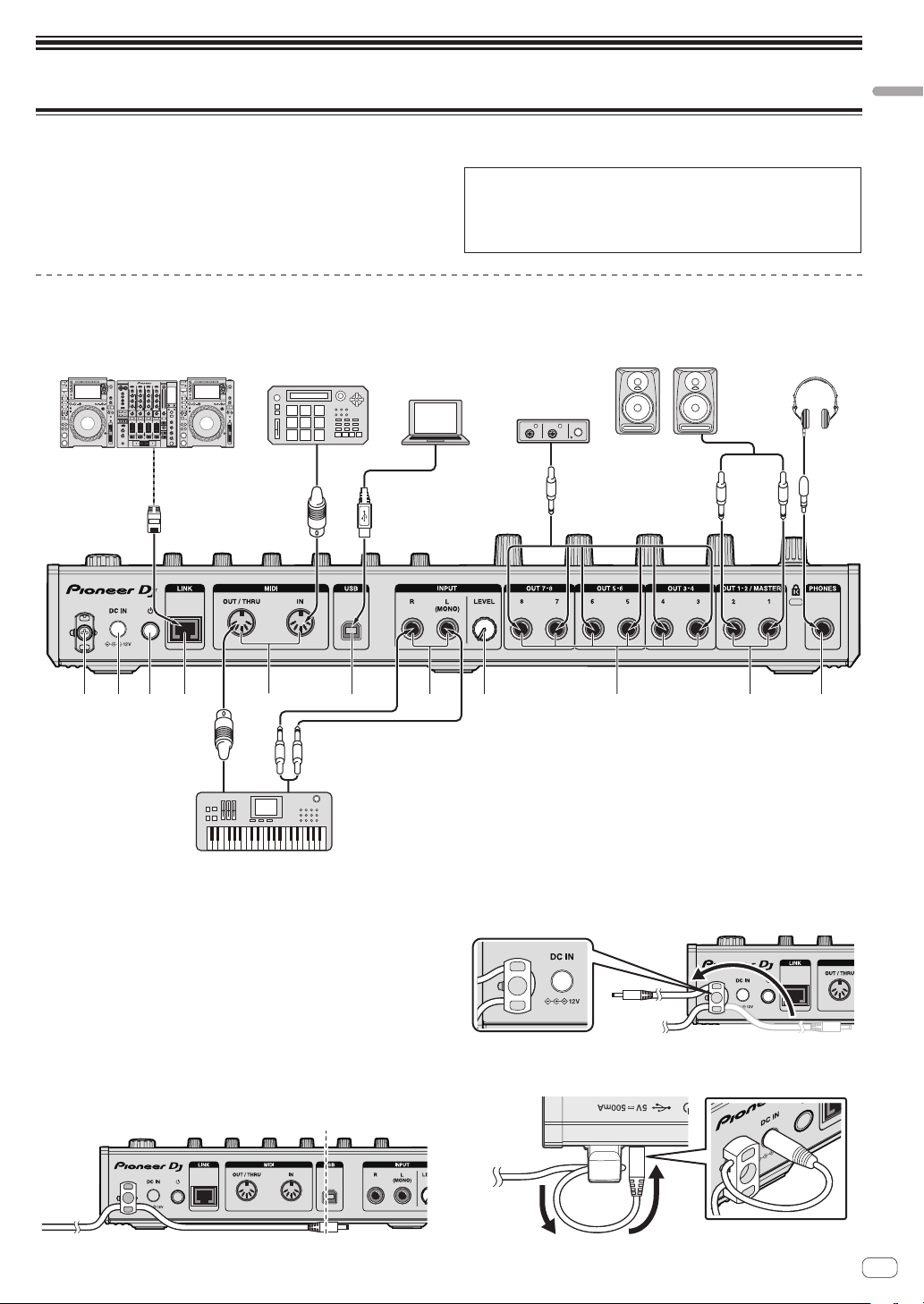
Connections
Be sure to turn off the power and unplug the power cord from the power
outlet whenever making or changing connections.
Connect the power cord after all the connections between devices have
been completed.
Be sure to use the power cord, AC adapter, USB cable and LAN cable
included with this product.
Connecting the input/output terminals
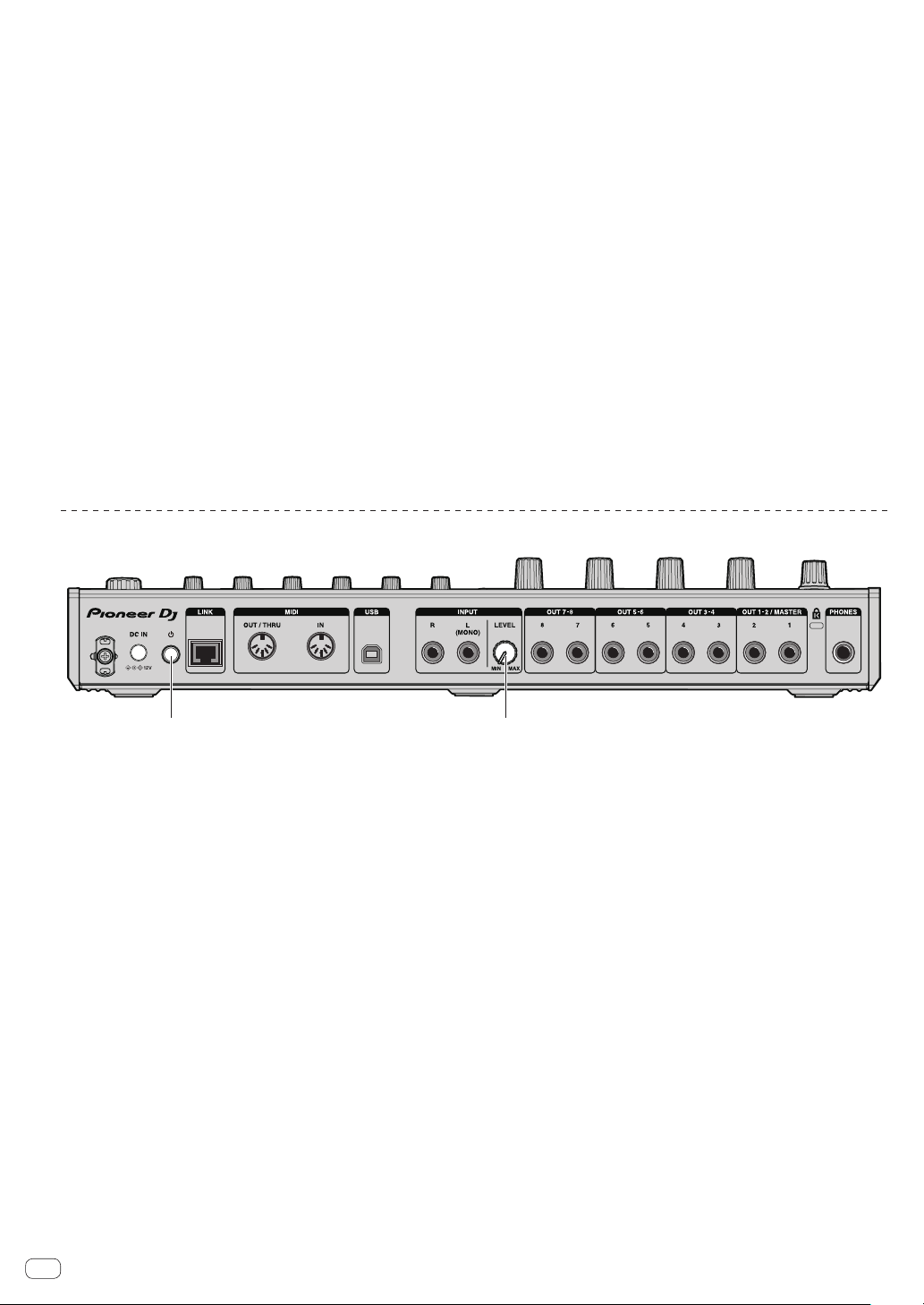
Rear panel
External sequencer, etc.
Refer to the operating instructions for the component to be connected.
! When using a LAN cable for connection, be sure to use either the
LAN cable included with this product or an STP (shielded twisted
pair) cable.
! Do not disconnect the LAN cable when information is being
shared using PRO DJ LINK.
Computer
Audio I/F
Connections and part names
Headphones
1 2
3 4 6 8 b5 7 9
1 Cord hook
Hook the AC adapters’ power cord here.
! The sound will be interrupted if the AC adapter’s power cord is
disconnected from the unit during playback.
Using the cord hook
Hook the AC adapter’s power cord onto the cord hook to fasten it in
place. This prevents the power cord from being accidentally pulled, causing the plug to get disconnected from the terminal.
! The sound will be interrupted if the AC adapter’s power cord is dis-
connected from the unit during playback.
1 As shown on the diagram below, extend the tip of the power cord to
approximately the center of the rear panel of this unit and hook the
power cord onto the bottom side of the cord hook.
a
2 As shown on the diagram below, move the tip of the power cord back
in the opposite direction past the top of the cord hook, and hook the
power cord onto the top side of the cord hook.
3 Turn the tip of the power cord so that it is facing towards you, then
turn it back to create a ring as shown in the diagram and insert it into
the [DC IN] terminal of this unit.
En
5
2 DC IN terminal
r
USB STOP butto
Connect the DC plug of the included AC adapter.
! Connect the power cord after all the connections between
devices have been completed.
! Be sure to use the included power cord.
3 u switch
4 LINK terminal
Connect a PRO DJ LINK compatible device with the LAN cable
(included).
5 DIN MIDI IN and DIN MIDI OUT/THRU terminals
These are DIN type terminals. Connect another MIDI device.
6 USB-B terminal
Connects to a computer.
! A USB hub cannot be used.
! To maintain the performance, connect this unit and computer
directly using a USB cable compliant with USB 2.0.
7 INPUT terminals
Connect a DJ player or other line level output device. When
[L (MONO)] only is connected, the audio input to [L (MONO)] is also
input to the [R].
8 INPUT LEVEL control
9 OUT3-8/ASSIGNABLE OUT terminals
a OUT1-2/MASTER/ASSIGNABLE OUT terminals
b Kensington security slot
c PHONES terminals
Connect headphones here.
Supports a stereo phone plug (ø 6.3 mm).
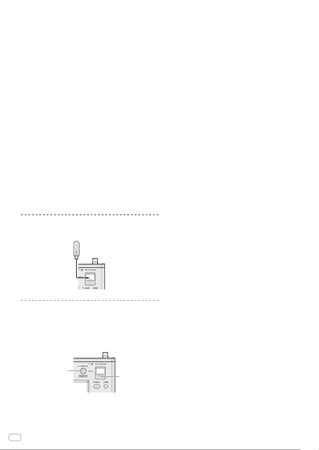
Connecting USB devices
Connect the USB device to the USB device insertion slot.
Disconnecting USB devices
1 Press and hold the [USB STOP] button until the USB
indicator stops flashing.
Do not remove the USB device or turn Off the power of the unit while
the USB indicator is flashing. The management data in the unit may get
deleted. Also, the USB device may become unreadable.
n
USB indicato
2 Disconnect the USB device.
6
En
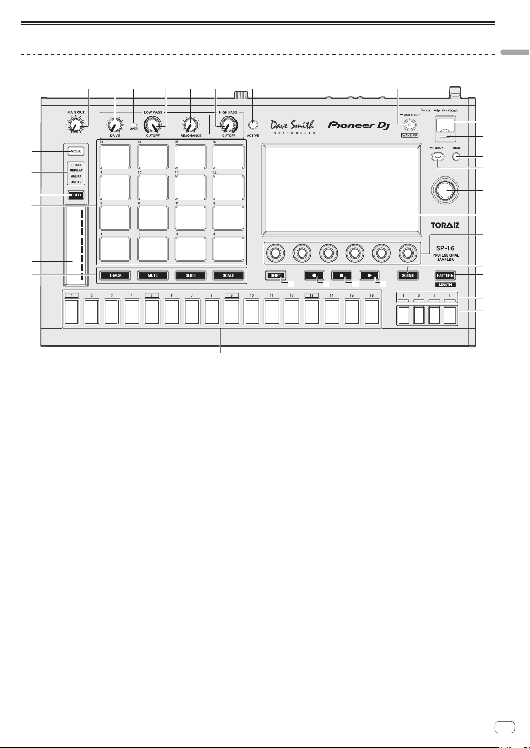
Part names and functions
1 4 6 8
2 3 5 7
9
a
b
h
d
e
c
f
g
i
j
o
p
q
s
u
r
t
Top panel
Connections and part names
n m l k
1 MAIN OUT control
Adjusts the volume of all outputs.
Adjusts the audio level output from the [OUT1-2/MASTER/
ASSIGNABLE OUT] terminals, [OUT3-8/ASSIGNABLE OUT] terminals, and [PHONES] terminal.
2 DRIVE control
Adjusts the drive amount of the analog filter.
= Using the analog filter (p. 15 )
3 OVER indicator
Lights when audio with an excessive volume level is input.
4 LOW PASS CUTOFF control
Adjusts the cutoff of the low-pass filter.
=
Using the analog filter (p. 15 )
5 LOW PASS RESONANCE control
Adjusts the resonance of the low-pass filter.
=
Using the analog filter (p. 15 )
6 HIGH PASS CUTOFF control
Adjusts the resonance of the high-pass filter.
=
Using the analog filter (p. 15 )
7 ACTIVE button
Turns the analog filter on or off.
= Using the analog filter (p. 15 )
8 USB STOP/WAKE UP button
USB STOP: If this is pressed for at least 2 seconds, the USB device
becomes able to be disconnected from the unit.
= Disconnecting USB devices (p. 6 )
WAKE UP: Cancels the auto standby mode.
=
About the auto standby function (p. 44 )
9 USB device insertion slot
Load the USB device here.
= Connecting USB devices (p. 6 )
a USB indicator
It lights, flashes when this unit is communicating with the USB
device.
= Connecting USB devices (p. 6 )
b HOME button
Displays the HOME screen on the touch display.
c BACK button
The screen moves back to the layer above.
= Operation with hardware (p. 27 )
d Rotary selector
Turning the rotary selector when selecting a project, track, setting
item, etc. moves the focus. To enter the selection, press the rotary
selector.
e Touch display
Displays various information.
f Parameter adjustment knobs
Adjusts the parameters corresponding to the parameter adjustment
knobs.
=
Using the step keys parameter adjustment knobs (p. 14 )
g SCENE button
Turns the scene switching mode on or off.
= Switching the scene (p. 12 )
h PATTERN button
Turns the pattern switching mode on or off.
= Switching the pattern (p. 12 )
i Playback bar display indicators
Displays the bar position of the pattern being played.
j Bar selection keys
Selects the bars to display for the 16 step keys.
En
7
k d button
1 2
Plays or pauses a pattern.
= Playing and stopping a pattern (p. 11 )
l g button
Stops a pattern.
= Playing and stopping a pattern (p. 11 )
m k button
Records a pad performance.
= Recording a performance (dynamic recording) (p. 13 )
n SHIFT button
When another button is pressed while pressing the [SHIFT] button, a
different function is called out.
o 16-step keys
When using with the pattern switching function
= Switching the pattern (p. 12 )
When using with the scene switching function
= Switching the scene (p. 12 )
When using with the step recording function
= Programming triggers (step recording) (p. 14 )
When using with the step modulation function
= Inputing parameter changes on a step level (step modulation)
(p. 14 )
p Pad mode selection button
Selects the operation mode of the performance pads.
Rear panel
q Touch strip
Adjusts the effect of each mode of the touch strip.
= Using the touch strip function (p. 15 )
r Performance pads
When using with the track switching function
= Switching the track (TRACK mode) (p. 13 )
When using with the mute function
=
Muting a track (MUTE mode) (p. 13 )
When using with the sample performance function
= Playing a sample sound (p. 13 )
When using with the slice performance function
= Playing a slice performance (SLICE mode) (p. 13 )
When using with the scale performance function
= Playing a scale performance (SCALE mode) (p. 13 )
s HOLD button
Holds the effect of the touch strip.
= Using the touch strip function (p. 15 )
t MODE indicator
Displays the selected touch strip mode.
= Using the touch strip function (p. 15 )
u MODE button
Each press of this switches the touch strip mode.
=
Using the touch strip function (p. 15 )
1 u switch
Turns this unit’s power on and off.
= Starting the system (p. 11 )
2 INPUT LEVEL control
Adjusts the level of the audio input to the [INPUT] terminals.
En
8
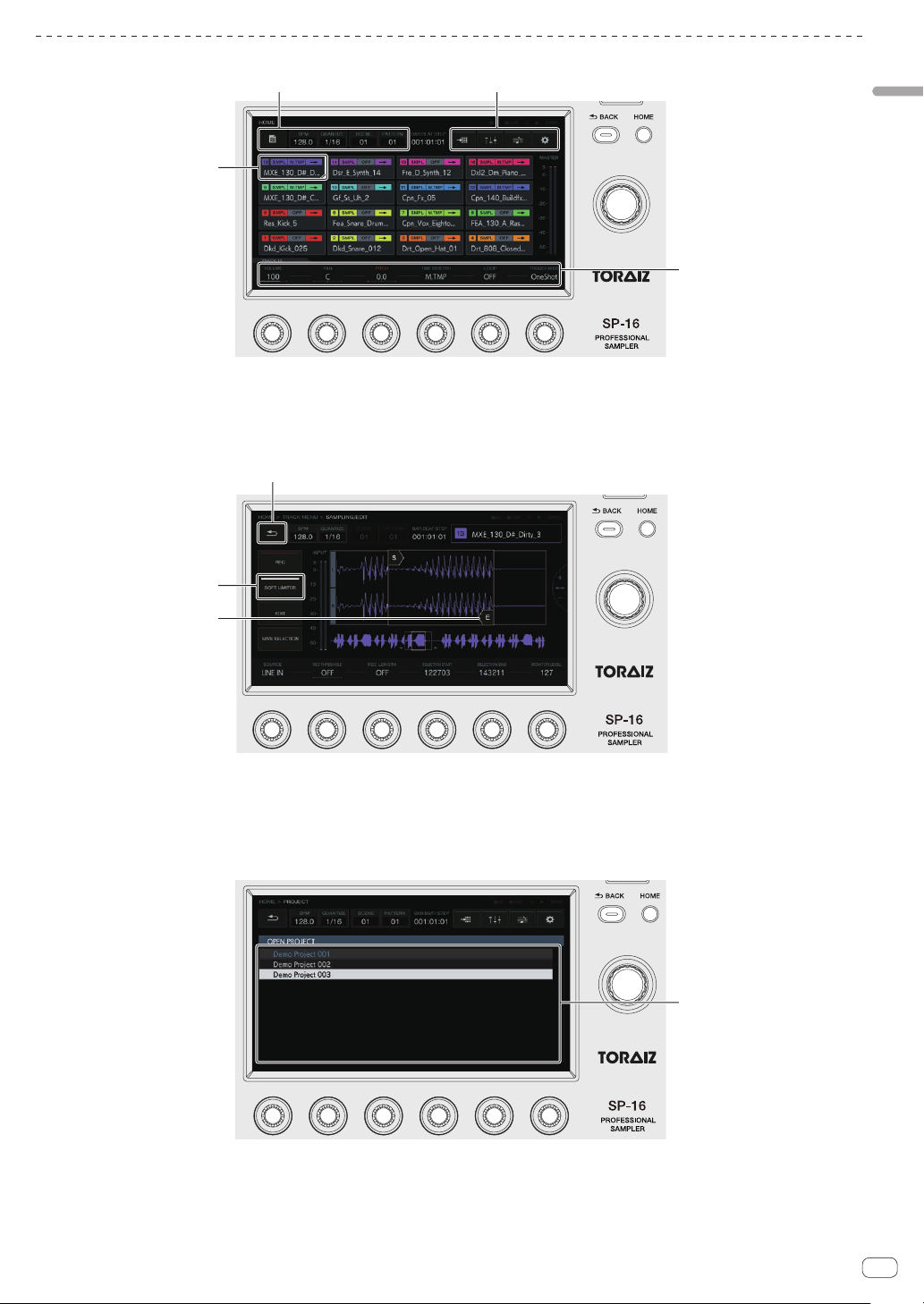
Description of the touch display
1
4
6
5
8
2
3
Connections and part names
1 Button with focus
Tap to move the focus. Tapping twice switches to a screen to operate
the corresponding item.
2 Button
Switches screens and displays pop-ups.
7
5 Touch object
Touch to enable operation of the object. Sliding your finger while it is
touching the object moves the object.
6 Button with indicator
Tap to switch the function on or off.
The button lights or flashes when the function is on.
3 Menu button
Tap to switch menus.
4 Parameter display area
Operating the parameter adjustment knobs below the display
changes the values.
7 Back button
Tap to return to the screen of the level above. The same operation
can be performed with the [BACK] button at the top right of the
display.
8 List
Turning the rotary selector on the right side of the display changes
the list selection position. Also, pressing the rotary selector enters
the list selection.
Pressing the [BACK] button cancels the selection.
!
Nothing can be operated by touch operation.
En
9
Project structure
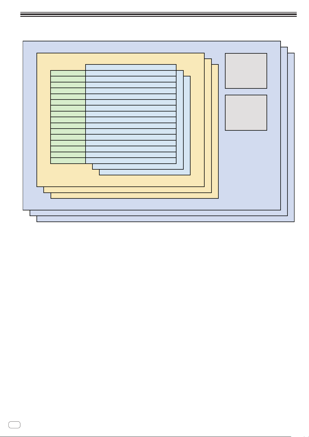
The data structure of this unit is as shown in the figure below.
PROJECT
TRACK1
TRACK2
TRACK3
TRACK4
TRACK5
TRACK6
TRACK7
TRACK8
TRACK9
TRACK10
TRACK11
TRACK12
TRACK13
TRACK14
TRACK15
TRACK16
SCENE
PATTERN
TRACK1 Sequence
TRACK2Sequence
TRACK3Sequence
TRACK4Sequence
TRACK5Sequence
TRACK6Sequence
TRACK7Sequence
TRACK8Sequence
TRACK9Sequence
TRACK10Sequence
TRACK11Sequence
TRACK12Sequence
TRACK13Sequence
TRACK14Sequence
TRACK15Sequence
TRACK16Sequence
ARRANGEMENT
ROUTING
PROJECT
A project represents one work unit for the user. Each project stores 16 scenes, one arrangement, and output routing information. This unit allows
multiple projects to be created as long as internal memory space is available.
TRACK
Tracks consist of sample players (sample tracks only), amplifier envelope (sample tracks only), insert effects, and sequences. Two track types exist:
sample tracks and through tracks.
A sample track is used when setting a sample in internal memory as a sound source. A through track is used when setting an external input as a sound
source.
Sound sources can thus be assigned like follows: a bass drum to track 1, a snare drum to track 2, and a synthesizer connected to an external input to
track 3.
SCENE
Scenes store 16 patterns and information on the assignments to sample tracks.
Since the samples to assign to tracks can be changed for each scene, the tune can be greatly changed by changing the scene.
PATTERN
A pattern combines the sequences to create in the 16 tracks and is one finished section of a performance. A pattern length can be set on a step level
from a minimum of 4 steps to a maximum of 4 bars (64 steps).
ARRANGEMENT
An arrangement is created by the ARRANGER function which arranges and plays patterns in order. The playback count and BPM can be set individually for each pattern. Editing of an arrangement is performed in the ARRANGER screen, and you can duplicate, paste, delete, and listen to patterns.
10
En
Operation
Starting the system
1 Make all the connections, then plug the power cord
into a power outlet.
= Connections (p. 5 )
2 Press the [u] switch on the rear panel of the unit.
This unit’s indicators light up and the power turns on.
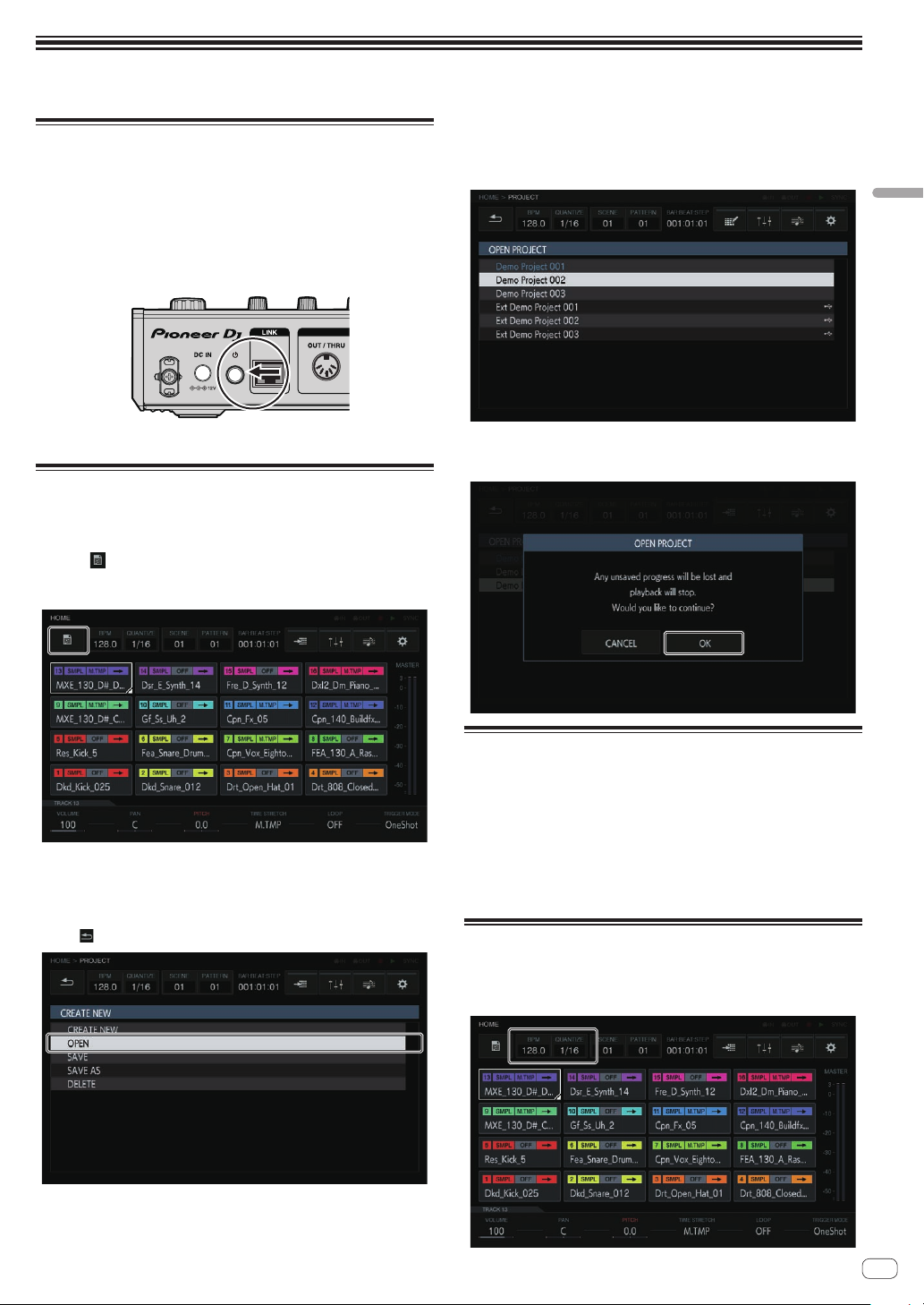
Loading a project
The following explanations starts from the home screen. To go to the
home screen, press the [HOME] button.
1 Tap [ PROJECT].
The PROJECT screen appears on the touch display. In the project screen,
you can perform operations such as loading and saving projects.
3 Turn the rotary selector to select a demo project and
then press the rotary selector.
A confirmation pop-up appears.
Operation
4 Tap [OK].
Tap [OK] to load the project.
2 Turn the rotary selector to select [OPEN] and then
press the rotary selector.
The project list appears.
! To return to a higher level, press the [BACK] button or tap
[ BACK] on the touch display.
Playing and stopping a pattern
Press the [d] button.
The current pattern of the demo project plays. The [d] button is lit in
green during playback.
! Pressing the [d] button during playback pauses playback.
! Pressing the [g] button during playback stops playback while
allowing reverberations and other sound to remain, and returns
to the beginning of the pattern. Pressing the [g] button again
stops all sounds including the reverberations.
Changing the BPM
1 Tap [BPM/QUANTIZE].
The BPM/QUANTIZE pop-up appears.
En
11
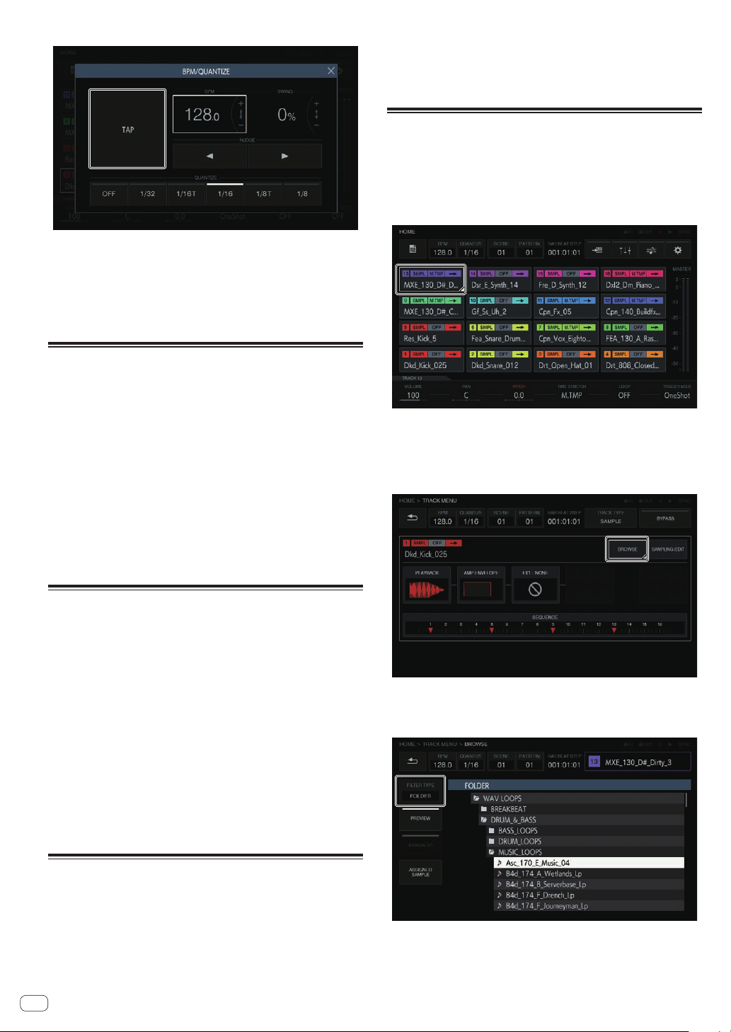
2 Set the BPM value.
The BPM value can be set in the following two ways.
!
Tap [TAP] at least two times with a finger in time with the quarter notes.
— The average value of the interval at which [TAP] was tapped by a
finger is set as the BPM.
! Tap to select the BPM display area and then turn the rotary selector.
— The BPM value is changed.
— If the rotary selector is turned while pressing the [SHIFT] button,
the BPM can be set in 0.1 increments.
Switching the pattern
1 Press the [PATTERN] button.
The unit enters the pattern switching mode and the [PATTERN] button
lights in white. The 16-step keys are lit in the current scene color during
pattern switching mode.
! 16 patterns can be held in one scene. Each pattern is assigned to
one of the 16-step keys.
! All patterns with a sequence recorded are dimmed, all patterns
without a sequence recorded are off, and the current scene is full
lit.
2 Press a 16-step key with a sequence recorded.
The pattern assigned to the pressed 16-step key plays.
! Pattern switching timing will be in accordance with the
PATTERN QUANTIZE setting value set in UTILITY.
! The pressed 16-step key flashes during pattern switching.
! Exit pattern switching mode by pressing [PATTERN] button.
2 Press a bar selection key.
Set the length of the pattern on a bar level. The bar selection keys from
bar selection key [1] to the pressed bar selection key light in blue.
! Pressing the [PATTERN] button ends the pattern length setting
mode.
Loading a sample to a track
1 Tap the track to which you wish to load the sample
and then tap again while selected.
The track menu screen appears.
! You can also go to the track menu screen by turning the rotary selec-
tor to select a track and then pressing the rotary selector.
2 Tap [BROWSE].
The browse screen appears. In the browse screen, you can search for
samples and load samples to tracks.
! You can also go to the browse screen by turning the rotary selector to
select [BROWSE] and then pressing the rotary selector.
Switching the scene
1 Press the [SCENE] button.
The unit enters the scene switching mode and the [SCENE] button lights
in white. The 16 step keys are lit in the scene colors during scene switching mode.
! 16 scenes can be held in one project. Each scene is assigned to
one of the 16 step keys.
! All patterns with a sequence recorded are dimmed, all patterns
without a sequence recorded are off, and the current scene is full
lit.
2 Press a 16-step key with a sequence recorded.
The scene is selected, and the unit switches to the state for selecting a
pattern in that scene.
! For details on switching the pattern, refer to Switching the
pattern.
! Exit scene switching mode by pressing the [SCENE] button.
! If the mode is exited without switching the pattern, the scene
returns to the one selected immediately before.
Changing the length of a pattern
1 Press the [PATTERN] button while pressing the [SHIFT]
button.
The unit enters the pattern length setting mode and the [PATTERN] button lights in white. The 16 step keys are lit in white and the bar selection
keys are lit in blue during pattern length setting mode.
A pattern length from a minimum of 8 steps to a maximum of 64
!
steps can be set.
En
12
3 Tap [FILTER TYPE] and select [FOLDER].
The internal memory and USB device details are displayed in a tree on
the right part of the touch display.
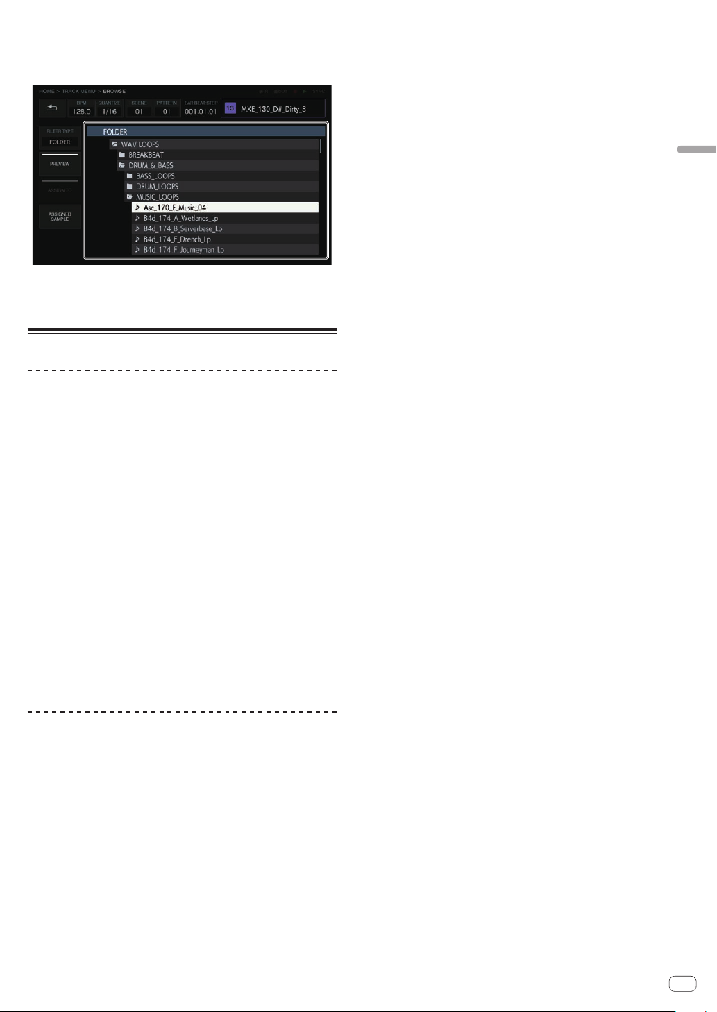
4 Turn the rotary selector to select the sample you wish
to load and then press the rotary selector.
The sample is loaded to the track, and the name of the loaded sample is
displayed at the top right of the screen.
! Press the rotary selector when a folder is selected opens or closes
the folder.
! Turning the rotary selector while pressing the [SHIFT] button moves
the focus on a folder basis (sample file lines are skipped).
Using the performance pads
Playing a sample sound
1 Press the [SLICE] button to turn the function off.
The [SLICE] button is set to the off state.
2 Press the [SCALE] button to turn the function off.
The [SCALE] button is set to the off state.
3 Hit the performance pads.
The sample assigned to each performance pad plays.
Muting a track (MUTE mode)
The track corresponding to a performance pad can be muted by pressing
the [MUTE] button.
1 Press the [MUTE] button.
The [MUTE] button lights in white.
2 Press the performance pad corresponding to the track
you wish to mute.
The performance pad corresponding to the muted track turns off.
! Mute can be set for multiple tracks at the same time.
! To cancel mute, press the performance pad corresponding to the
muted track again.
! If a performance pad is pressed while pressing the [SHIFT] button,
the corresponding tracks other than that are muted. Performing the
same operation again cancels mute for all of them.
3 Press the [MUTE] button again.
The [MUTE] button turns off and the mute mode ends.
Playing a slice performance (SLICE mode)
Sliced sample sounds corresponding to performance pads can be
played by pressing the [SLICE] button.
1 Select the track that has the sample for which you
wish to play a slice performance assigned.
= Switching the track (TRACK mode) (p. 13 )
2 Press the [SLICE] button.
The [SLICE] button lights in white.
! The sample is sliced equally into 16 slices and the slices are
assigned in order to the performance pads.
3 Hit the performance pads.
The sample assigned to each performance pad plays.
4 Press the [SLICE] button again.
The [SLICE] button turns off and the slice performance mode ends.
Operation
Recording a performance (dynamic
recording)
1 Press the [k] button.
The [k] button lights in red and recording is enabled.
2 Press the [d] button.
The [d] button lights in green and the sequence plays while recording
is enabled.
3 Hit the performance pads to record triggers.
A trigger is recorded at the timing that the pad is tapped. The step key to
which the trigger was input lights or flashes in the track color.
Using the operation modes of the
performance pads
Four operation mode types are available.
Switching the track (TRACK mode)
The track corresponding to a performance pad can be switched by pressing the [TRACK] button.
1 Press the [TRACK] button.
The [TRACK] button lights in white.
2 Press the performance pad corresponding to the track
to which you wish to switch.
The track corresponding to the pressed performance pad is set as the
current track.
3 Press the [TRACK] button again.
The [TRACK] button turns off and the track selection mode ends.
Playing a scale performance (SCALE mode)
A samples of a scale corresponding to performance pads can be played
by pressing the [SCALE] button.
1 Select the track that has the sample for which you
wish to play a scale performance assigned.
= Switching the track (TRACK mode) (p. 13 )
2 Press the [SCALE] button.
The [SCALE] button lights in white.
! The sample ascends by each semitone on the chromatic scale, treat-
ing the bottom left performance pad as the keynote.
3 Hit the performance pads.
The sample with the scale assigned to each performance pad plays.
4 Press the [SCALE] button again.
The [SCALE] button turns off and the SCALE mode ends.
En
13
Using the step keys parameter adjustment knobs
Programming triggers (step recording)
1 Tap a track for step recording.
The sequence of the selected track is indicated on the 16-step keys.
A track can also be selected by turning the rotary selector.
!
! A track can also be selected by hitting a performance pad while the
[TRACK] button is in the ON state.
2 Press the 16-step keys to input triggers.
The step keys corresponding to the programmed sequence lights in the
track color.
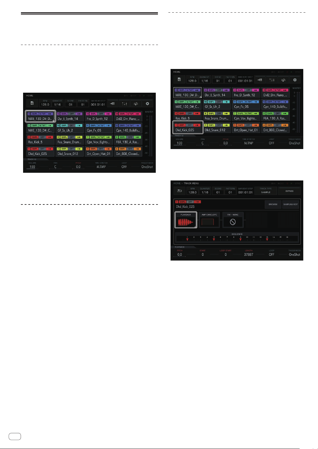
Inputing parameter changes on a step
level (step modulation)
1 Tap the track which you wish to change and tap again
to enter.
The track menu screen appears.
! You can also go to the track menu screen by turning the rotary selec-
tor to select a track and then pressing the rotary selector.
2 Tap [PLAYBACK] and tap again in the selected state.
The playback screen appears.
! You can also go to the playback screen by turning the rotary selector
to select [PLAYBACK] and then pressing the rotary selector.
Changing track parameters
1 Press the [HOME] button.
The HOME screen appears.
2 Select the track that has the sample for which you
wish to change the parameters assigned.
= Switching the track (TRACK mode) (p. 13 )
3 Turn the parameter adjustment knobs.
The parameter corresponding to each parameter adjustment knob
changes. The parameter values are displayed at the bottom of the touch
display.
! Turn the parameter 1 adjustment knob (changes the volume).
The volume of the track changes.
! Turn the parameter 2 adjustment knob (changes the panning
position).
The panning position of the track changes.
! Turn the parameter 3 adjustment knob (changes the pitch of the
sound).
The sound pitch of the track changes.
! Turn the parameter 4 adjustment knob (sets the time stretch).
The method of stretching a sample to synchronize the BPM is set.
! Turn the parameter 5 adjustment knob (sets loop playback).
Sample loop playback is switched.
! Turn the parameter 6 adjustment knob (sets the sample playback
method).
The method of playing of a sample in response to a trigger is
switched.
! For details on the operation when each adjustment knob is turned,
refer to Making overall settings, adjustments, and checks (HOME)
(p. 18 ).
3 Turn a parameter adjustment knob while pressing the
16-step key of the step for which you wish to change the
parameter.
! The name of a parameter target for step modulation is red.
14
En

Using the touch strip function
Using PITCH
1 Press the [MODE] button to select [PITCH].
[PITCH] of the [MODE] indicators lights.
! Each press of the [MODE] button changes the [MODE] indicator in
the order of [PITCH] l [REPEAT] l [USER1] l [USER2] l and so
on.
2 Press and hold down the performance pad that has
the sample for which you wish to change the pitch
assigned.
The sample sound assigned to the performance pad plays.
3 Touch the touch strip to change the parameter.
The pitch of the sample sound changes according to position touched
on the touch strip. Also, the touch strip indicator of the position touched
on the touch strip lights.
! The range for changing the pitch using the touch strip is as follows.
Very bottom: -2 semitones
Very top: +2 semitones
! Pressing a performance pad from the state of touching the touch
strip also changes the pitch.
! The effect using the touch strip only operates while you continue
pressing a performance pad. It cannot be used in a sequence.
Using REPEAT
1 Press the [MODE] button to select [REPEAT].
[REPEAT] of the [MODE] indicators lights.
! Each press of the [MODE] button changes the [MODE] indicator in
the order of [PITCH] l [REPEAT] l [USER1] l [USER2] l and so
on.
2 Press and hold down the performance pad that has
the sample you wish to repeatedly play assigned.
The sample sound assigned to the performance pad plays.
3 Touch the touch strip to change the parameter.
The sample sound plays repeatedly according to position touched on the
touch strip. Also, the touch strip indicator of the position touched on the
touch strip lights.
! The range for the repeat interval using the touch strip is as follows.
1/4 beat (quarter note) l 1/8 beat (eight note) l 1/16 beat (sixteenth note) l 1/32 beat (thirty-second note)
! Pressing a performance pad from the state of touching the touch
strip also plays the sample sound repeatedly.
! The effect using the touch strip only operates while you continue
pressing a performance pad. It cannot be used in a sequence.
4 Change the force applied to the performance pad.
The sample volume changes according to the increase or decrease in
force applied to the performance pad. Pressing with a stronger force
increases the volume and pressing with a weaker force decreases the
volume.
Using with USER setting
3 Press and hold down the performance pad that has
the sample for which you wish to change the parameter
assigned.
The sample sound assigned to the performance pad plays.
4 Touch the touch strip to change the parameter.
The sample sound changes according to position touched on the touch
strip. Also, the touch strip indicator of the position touched on the touch
strip lights.
! Pressing a performance pad from the state of touching the touch
strip also plays the sample sound repeatedly.
! The effect using the touch strip only operates while you continue
pressing a performance pad. It cannot be used in a sequence.
Using HOLD
1 Press the [HOLD] button.
The [HOLD] button lights.
2 Touch the touch strip.
Hold is performed and the touch strip indicator lights at the position the
touch strip was last touched.
! If the mode is switched, hold is canceled and the [HOLD] button
turns off.
Using the analog filter
Use the dials to sculpt your sound – manipulating Drive, Cut Off and
Resonance – and add true analogue warmth and presence.
1 Press the [ACTIVE] button.
The analog filter effect is enabled (activated). In the active state, the
button is lit in red.
2 Turn the [LOW PASS CUTOFF] control.
The low-pass filter’s cutoff frequency changes.
! Turning the control counterclockwise moves the cutoff frequency
toward the lower frequencies, and turning it clockwise moves the
cutoff frequency toward the higher frequencies.
3 Turn the [LOW PASS RESONANCE] control.
The low-pass filter’s resonance changes.
! Turning the control counterclockwise reduces the resonance of
sound in the vicinity of the cutoff frequency, and turning it increases
the resonance.
4 Turn the [HIGH PASS CUTOFF] control.
The high-pass filter’s cutoff frequency changes.
! Turning the control counterclockwise moves the cutoff frequency
toward the lower frequencies, and turning it clockwise moves the
cutoff frequency toward the higher frequencies.
5 Turn the [DRIVE] control.
The analog filter’s drive amount is adjusted.
! Turning the control counterclockwise reduces the effect, and turning
it clockwise increases the effect.
! If the effect is made large, the output sound may be distorted. When
that happens, the OVER indicator lights in amber so that you can
know that a distortion effect is occurring due to the analog filter
circuit.
Operation
1 Press the [MODE] button to select [USER1] or [USER2].
[USER1] or [USER2] of the [MODE] indicators lights.
! Each press of the [MODE] button changes the [MODE] indicator in
the order of [PITCH] l [REPEAT] l [USER1] l [USER2] l and so
on.
2 Set the parameters to be changed with [USER1] or
[USER2].
Configure the settings of the parameters on the TOUCH STRIP SETTING
(USER1) screen or TOUCH STRIP SETTING (USER2) screen.
= Switching the track (TRACK mode) (p. 13 )
En
15
 Loading...