


PIONEER CORPORATION 4-1, Meguro 1-Chome, Meguro-ku, Tokyo 153-8654, Japan
PIONEER ELECTRONICS SERVICE INC. P.O.Box 1760, Long Beach, CA 90801-1760 U.S.A.
PIONEER EUROPE N.V. Haven 1087 Keetberglaan 1, 9120 Melsele, Belgium
PIONEER ELECTRONICS ASIACENTRE PTE.LTD. 253 Alexandra Road, #04-01, Singapore 159936
C PIONEER CORPORATION 2000
K-ZZS. JAN. 2000 Printed in Japan
ORDER NO.
CRT2474
CD PLAYER
FORD
CONTENTS
1. SAFETY INFORMATION ............................................2
2. EXPLODED VIEWS AND PARTS LIST.......................2
3. BLOCK DIAGRAM AND SCHEMATIC DIAGRAM .....5
4. PCB CONNECTION DIAGRAM ................................12
5. ELECTRICAL PARTS LIST ........................................14
6. ADJUSTMENT..........................................................16
7. GENERAL INFORMATION .......................................20
7.1 DIAGNOSIS ........................................................20
7.1.1 TEST MODE ..............................................20
7.1.2 DISASSEMBLY .........................................23
7.2 IC ........................................................................25
7.3 EXPLANATION ...................................................27
7.3.1 CIRCUIT DESCRIPTIONS .........................27
7.3.2 MECHANISM DESCRIPTIONS.................41
- The CD mechanism employed in this model is one of S8.1 series.
YPM-2106ZF UC
2
YPM-2106ZF
This service manual is intended for qualified service technicians; it is not meant for the casual do-it-yourselfer.
Qualified technicians have the necessary test equipment and tools, and have been trained to properly and safely repair
complex products such as those covered by this manual.
Improperly performed repairs can adversely affect the safety and reliability of the product and may void the warranty.
If you are not qualified to perform the repair of this product properly and safely; you should not risk trying to do so
and refer the repair to a qualified service technician.
1. SAFETY INFORMATION
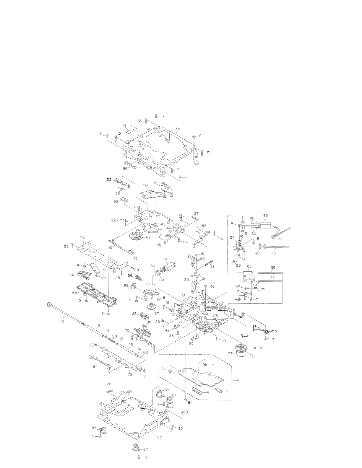
2. EXPLODED VIEWS AND PARTS LIST
2.1 CD MECHANISM

3
YPM-2106ZF
1 Control Unit CWX2412
2 Connector(CN802) CKS2192
3 Connector(CN801) CKS2193
4 Connector(CN901) CKS2767
5 Connector(CN101) CKS3486
6 Screw BMZ20P030FMC
7 Screw BSZ20P040FMC
8 Screw(M2x3) CBA1077
9 Screw(M2x6) CBA1489
10 Screw CBA1243
11 Screw(M2x4) CBA1362
12 Washer CBF1037
13 Washer CBF1038
14 Washer CBF1060
15 Spring CBH2372
16 Spring CBH2079
17 Spring CBH2117
18 Spring CBH2314
19 Spring CBH2373
20 Spring CBH2282
21 Spring CBH2318
22 Spring CBH2115
23 Spring CBH2324
24 Spring CBH2118
25 Spring CBH2161
26 Spring CBH2163
27 Spring CBH2189
28 Spring CBH2249
29 Spring CBH2260
30 Spring CBH2262
31 Bracket CNC8568
32 Spring CBL1369
33 Connector CDE5531
34 Connector CDE5532
35 Shaft CLA3304
36 Screw(M2.6x6) CBA1458
37 Frame CNC8682
38 Frame CNC8603
39 Lever CNC8694
40 Arm CNC8663
41 Bracket CNC8567
42 •••••
43 Spacer CNM3315
44 Sheet CNM6659
45 •••••
46 •••••
47 Ball CNR1189
48 Belt CNT1086
49 Roller CNV4509
50 Arm CNV6102
51 Arm CNV6094
52 Arm CNV5248
53 Arm CNV6095
54 Guide CNV5254
55 Guide CNV5255
56 Gear CNV5257
57 Gear CNV5256
58 Guide CNV6176
59 •••••
60 Arm CNV6096
61 Arm CNV6031
62 Arm CNV5361
63 Guide CNV6012
64 Guide CNV5510
65 •••••
66 Guide CNV5751
67 Clamper CNV6013
68 Gear CNV5813
69 Motor Unit(M1) CXB5827
70 Screw Unit CXB4726
71 Chassis Unit CXB5811
72 Gear Unit CXB4728
* 73 Arm Unit CXB5753
74 Motor Unit(M2) CXB5828
75 Lever Unit CXB4730
76 Arm Unit CXB4731
77 Motor Unit(M3) CXB5829
78 Arm Unit CXB5689
79 Bracket Unit CXB4795
80 Screw JFZ20P025FMC
81 Screw JGZ17P025FZK
82 Washer YE20FUC
83 Pickup Unit(Service)(P8) CXX1285
84 Screw IMS26P030FMC
* 85 Gathering PCB CNX2982
86 Photo Transistor(Q1, 2) CPT231SXTU
87 Damper CNV5266
88 Rack CNV6014
89 Spring CBH2315
- CD MECHANISM SECTION PARTS LIST
Mark No. Description Part No.
Mark No. Description Part No.
NOTE:
- Parts marked by “*” are generally unavailable because they are not in our Master Spare Parts List.
- Screws adjacent to ∇ mark on the product are used for disassembly.

4
YPM-2106ZF
5
YPM-2106ZF
1
2
34
1
2
34
D
C
B
A
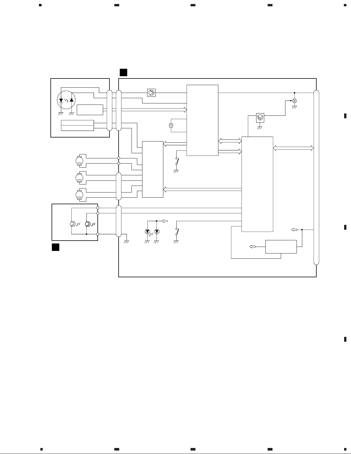
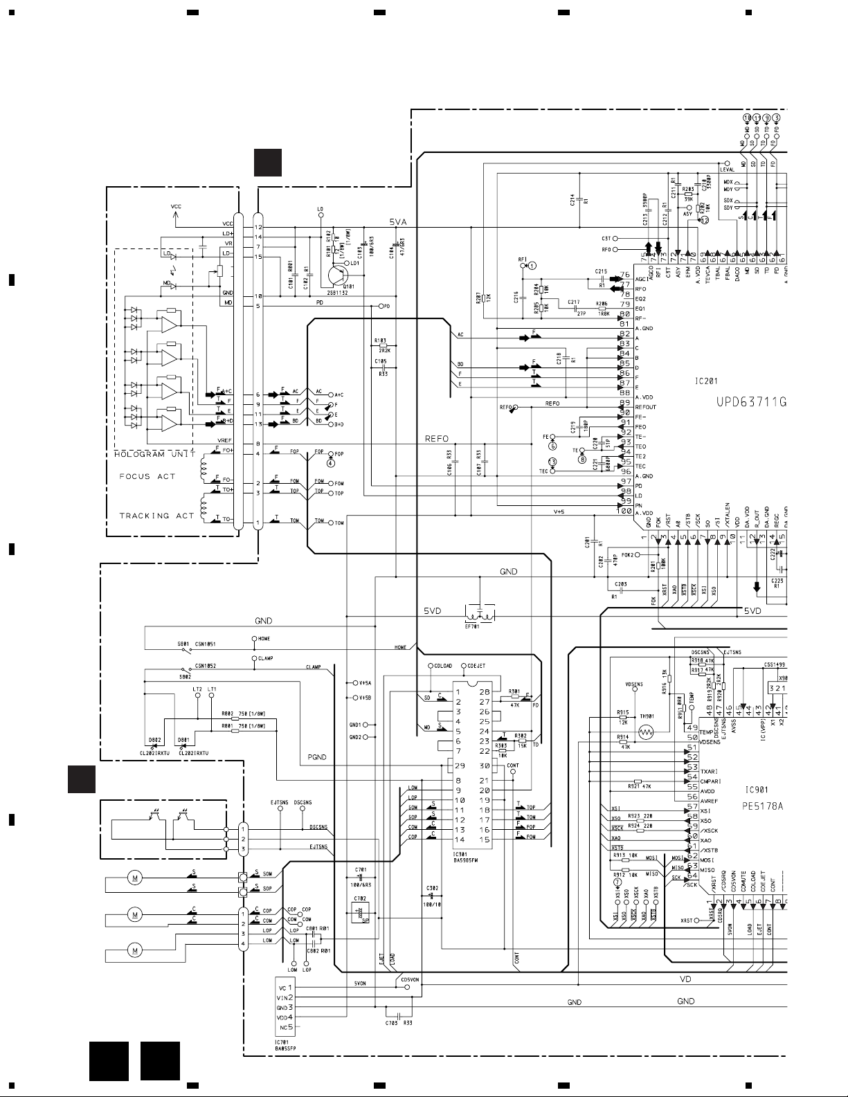
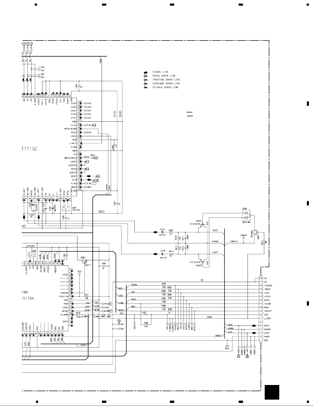
3. BLOCK DIAGRAM AND SCHEMATIC DIAGRAM
3.1 BLOCK DIAGRAM
M
M
M
LD
MD
HOLOGRAM
UNIT
FOCUS ACT
TRACKING ACT
LD+
MD
FO+
TO+
14
5
4
3
SPINDLE
MOTOR
CARRIAGE
MOTOR
LOADING
MOTOR
1
2
3
4
3
1
2
EJECT
SENSE
DISC SENSE
B
CN801
CN802
D802 D801
VD
S802
CLAMP
EJTSNS
CDMUTE
DSCSNS
CLAMP
CD5VON
VDD
IC 701
BA05SFP
IN
+5V REGULATOR
24
1
VD
A
Q101
CN101
FOP
TOP
A+C/F
B+D/E
98
LD L_OUT
PD
HOME
97
24
23
39
47
4
20
48
CD5VON
3
X201
TD/FD
CDLOAD/CDEJET
MISO/ejsw/MOSI/reset
cdsrq/brst/sck/cscd
XAO/xstb
XSI/XSO
xsck
LOCK/MIRR
FOK
SD/MD
RF-AMP, DSP,
SERVO, DAC,
LPF
IC 201
UPD63711GC
MICRO
COMPUTER
IC 901
PE5178A
16
CN901
3
18
17
IC 301
BA5985FM
S801
HOME
12
16
18
11
14
13
10
9
SOP
TOP
FOP
SOM
COP
COM
LOP
LOM
CD DRIVER
CONTROL UNIT
PICKUP UNIT(SERVICE)(P8)
PHOTO UNIT(S8F)
Q602
Q603
6
YPM-2106ZF
1
23
4
1
234
D
C
B
A
3P
22/6R3
RF-AMP, SERVO, DS
MICRO CO
CD DRIVER
5V REGULATOR
M3 CXB5829
M1 CXB5827
SPINDLE MOTOR
M2 CXB5828
CN801
CN802
LOADING MOTOR
CARRIAGE MOTOR
Q1 CPT231SXTU Q2 CPT231SXTU
PHOTO UNIT(S8F)
CN101
PICKUP UNIT
CONTROL UNIT
(SERVICE)(P8)
3.1 CD MECHANISM MODULE
B
A
B
A
7
YPM-2106ZF
5
6
78
5
6
78
D
C
B
A
4700P
16.934MHz
8.38MHz
RO COMPUTER
CN901
SWITCHES:
CONTROL UNIT
S801 : HOME SWITCH.....ON-OFF
S802 : CLAMP SWITCH....ON-OFF
The underlined indicates the switch position.
A
8
YPM-2106ZF
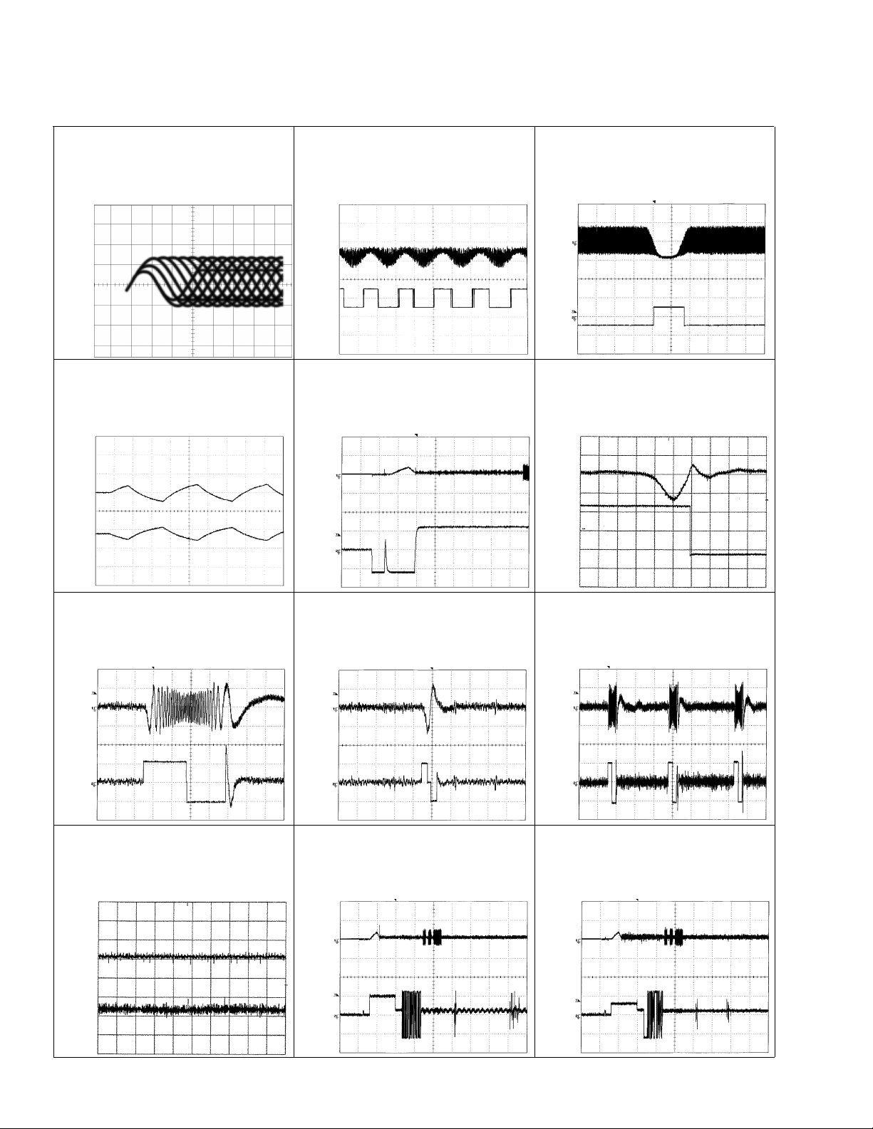
1 RFI 0.5V/div. 0.5µs/div.
Normal mode: play
1 CH1: RFI 1V/div.
2 CH2: MIRR 5V/div.
Test mode: Tracking open
0.5ms/div.
1 CH1: RFI 1V/div.
2 CH2: MIRR 5V/div.
Normal mode: The defect part
passes 800µm
0.5ms/div.
3 CH1: FD 0.5V/div.
4 CH2: FO+ 2V/div.
Test mode: No disc, Focus close
0.2s/div.
3 CH1: FD 0.5V/div.
5 CH2: FOK 2V/div.
Normal mode: Focus close
0.2s/div.
6 CH1: FE 0.5V/div.
7 CH2: XSI 2V/div.
Normal mode: Focus close
1ms/div.
REFO
→
8 CH1: TE 0.5V/div.
9 CH2: TD 0.5V/div.
Test mode: 32 tracks jump (FWD)
0.5ms/div.
8 CH1: TE 0.5V/div.
9 CH2: TD 0.5V/div.
Test mode: Single jump (FWD)
0.5ms/div.
8 CH1: TE 0.5V/div.
9 CH2: TD 0.5V/div.
Test mode: 100 tracks jump (FWD)
5ms/div.
6 CH1: FE 0.1V/div.
3 CH2: FD 0.2V/div.
Normal mode: Play
20ms/div.
3 CH1: FD 0.5V/div.
0 CH2: MD 1V/div.
Normal mode: Focus close (12cm)
0.5s/div.
3 CH1: FD 0.5V/div.
0 CH2: MD 1V/div.
Normal mode: Focus close (8cm)
0.5s/div.
REFO
→
REFO
→
REFO
→
REFO
→
REFO
→
REFO
→
GND
→
REFO
→
REFO
→
REFO
→
REFO
→
REFO
→
REFO
→
REFO
→
REFO
→
REFO
→
REFO
→
REFO
→
REFO
→
- Waveforms
Note:1. The encircled numbers denote measuring pointes in the circuit diagram.
2. Reference voltage
REFO:2.5V
REFO
→
REFO
→
REFO
→
REFO
→
9
YPM-2106ZF
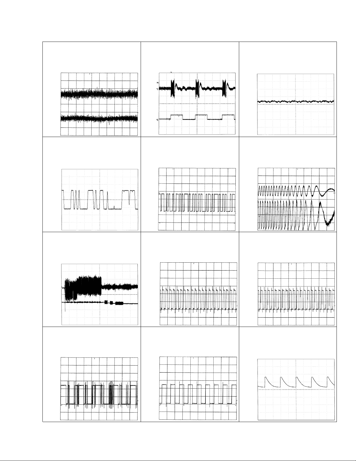
8 CH1: TE 0.2V/div.
9 CH2: TD 0.2V/div.
Normal mode: play
8 CH1: TE 0.5V/div.
! CH2: SD 0.5V/div.
TEST mode: 100 Tracks jump(FWD)
5ms/div.
0 MD 0.5V/div. 0.1s/div.
Normal mode: Play (12cm)
0 MD 1V/div. 10ms/div.
Normal mode:
Long Search (12cm)
@ EFM 1V/div. 5µs/div.
Normal mode: play
8 CH1: TE 1V/div.
# CH2: TEC 1V/div.
Test mode: Focus close
Tracking open
2ms/div.
8 CH1: TE 0.5V/div.
6 CH2: FE 0.5V/div.
Normal mode:
AGC after focus close
0.2s/div.
$ PLCK 2V/div. 0.5µs/div.
Normal mode: play
20ms/div.
% SCKO 2V/div. 1µs/div.
Normal mode: play
^ Dout 2V/div. 10µs/div.
Normal mode: play
& LRCK 2V/div. 20µs/div.
Normal mode: play
* VD 5V/div. 50ms/div.
Normal mode: No disc
GND
→
REFO
→
REFO
→
GND
→
REFO
→
REFO
→
REFO
→
REFO
→
REFO
→
REFO
→
REFO
→
REFO
→
REFO
→
GND
→
REFO
→
GND
→
REFO
→
GND
→
REFO
→
GND
→
REFO
→
10
YPM-2106ZF
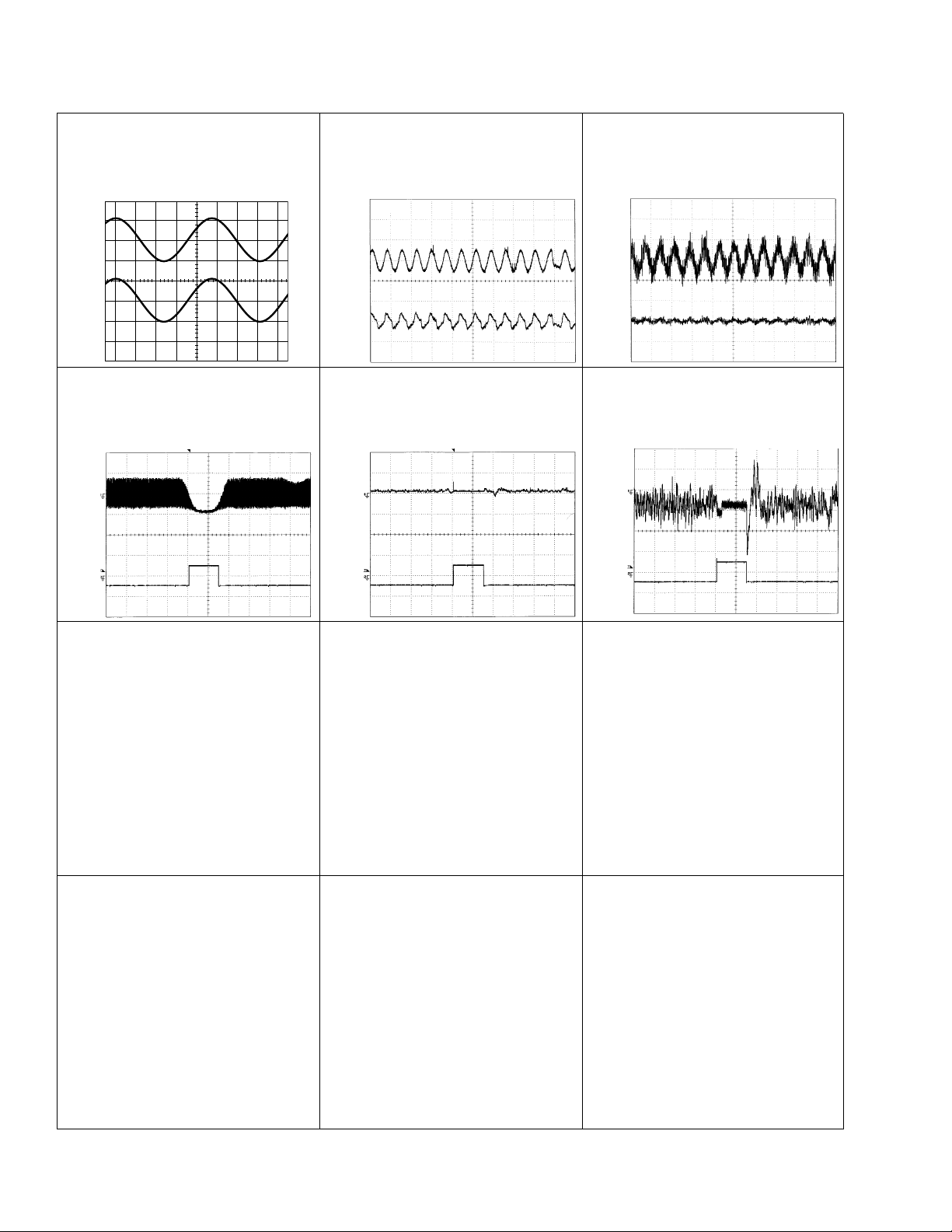
( CH1: R OUT 1V/div.
) CH2: L OUT 1V/div.
Normal mode: Play (1kHz 0dB)
6 CH1: FE 0.2V/div.
3 CH2: FD 0.5V/div.
Normal mode: During AGC
1ms/div.
8 CH1: TE 0.2V/div.
9 CH2: TD 0.5V/div.
Normal mode: During AGC
1 CH1: RFI 1V/div.
⁄ CH2: HOLD 5V/div.
Normal mode: The defect part passes
800µm(B.D)
0.2ms/div. 1ms/div.
0.5ms/div.
3 CH1: FD 0.5V/div.
⁄ CH2: HOLD 5V/div.
Normal mode: The defect part passes
800µm(B.D)
0.5ms/div.
9 CH1: TD 0.1V/div.
⁄ CH2: HOLD 5V/div.
Normal mode: The defect part passes
800µm(B.D)
0.5ms/div.
REFO
→
REFO
→
REFO
→
REFO
→
REFO
→
REFO
→
REFO
→
REFO
→
REFO
→
REFO
→
REFO
→
REFO
→

11
YPM-2106ZF
12
YPM-2106ZF
1
23
4
1234
D
C
B
A
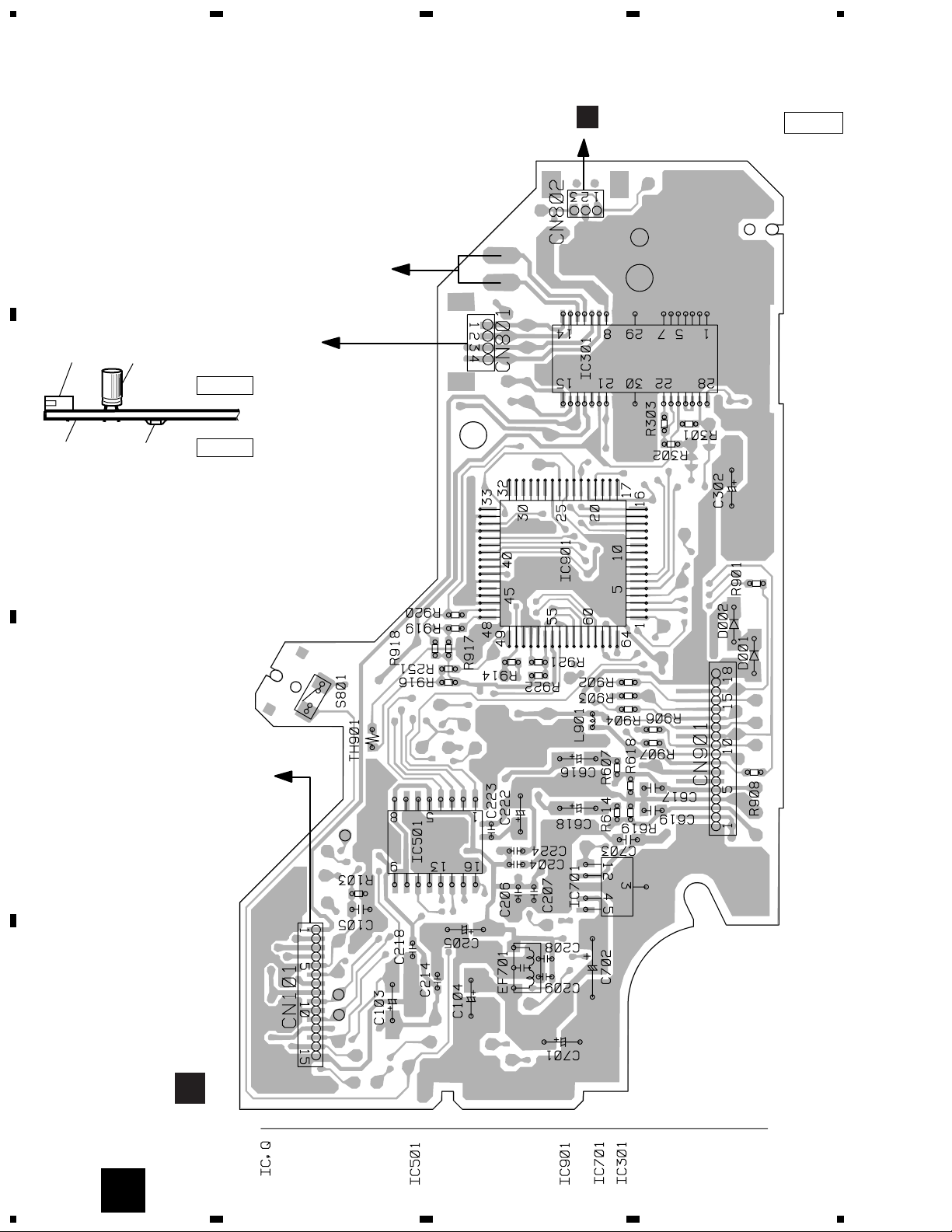
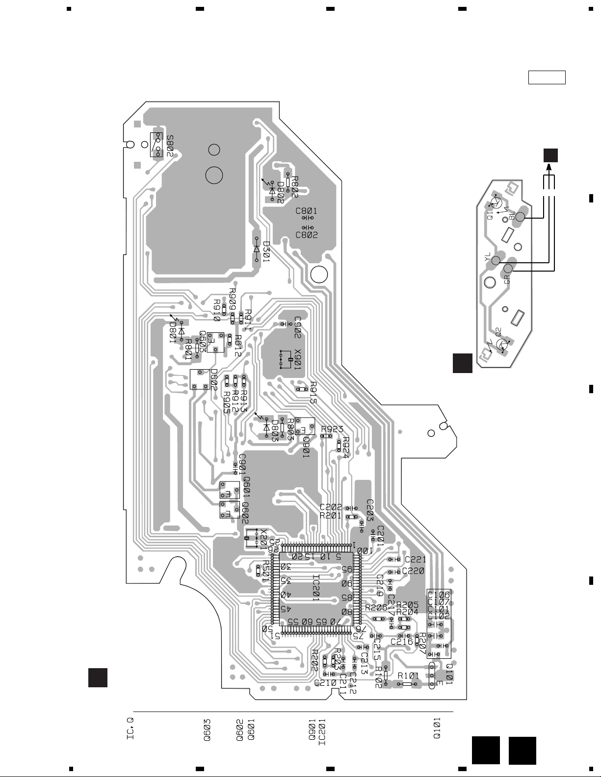
4. PCB CONNECTION DIAGRAM
4.1 CD MECHANISM MODULE
NOTE FOR PCB DIAGRAMS
1. The parts mounted on this PCB
include all necessary parts for
several destination.
For further information for
respective destinations, be sure
to check with the schematic dia-
gram.
2. Viewpoint of PCB diagrams
Capacitor
Connector
P.C.Board
Chip Part
SIDE A
SIDE B
CONTROL UNIT
HOME
E
F
REFO
M1 CARRIAGE MOTOR
M2 LOADING MOTOR
M3 SPINDLE MOTOR
PICKUP UNIT
(SERVICE)
SIDE A
A
B
A
13
YPM-2106ZF
1
2
34
1
2
34
D
C
B
A
CN802
321
PHOTO UNIT(S8)
A
B
A
CLAMP
SIDE B
CONTROL UNIT
A
B
 Loading...