

Pioneer WYD-GLFI SERIES, WD Series, YN Series Service Manual

Troubleshooting and Repair Guideline for
WD Indoor / YN Outdoor Units
Series DC Inverter Air Conditioner
WYD-GF16-S1-1714
SERVICE MANUAL
DC INVERTER
SPLIT WALL-MOUNTED
DUCTLESS HEAT PUMPS
WYD-GLFI SERIES
16 SEER VERSIONS

1
Contents
I. Electrical Control of Inverter Air Conditioner········································································2
1. Main compositions of the electrical control of inverter air conditioner·······························2
2. Wiring of Inverter AC Unit ································································································3
3. Current Flow ······················································································································4
4. Computer Control Function Flow Chart for Inverter AC Unit ············································5
5. Protection and Fault Codes·································································································5
II. Troubleshooting····················································································································8
1. According to the fault code ································································································8
(1) Display E1 or E2:·············································································································8
(2) Display E6························································································································9
(3) Display E3, E7, E8 ···········································································································10
(4) Display E4························································································································11
(5) Display EC ·······················································································································13
(6) Display EP························································································································14
(7) Display EA·······················································································································16
(8) Display EU·······················································································································17
(9) Display E9 (Firstly display P0 or P9, then change to E9)··················································18
(10) Display E0、E5··············································································································20
(11) Display EE ·····················································································································22
(12) Display P0······················································································································23
(13) Display P1······················································································································24
(14) Display P2······················································································································24
(15) Display P4······················································································································25
(16) Display P5······················································································································25
(17) Display P6······················································································································26
(18) Display P7······················································································································27
(19) Display P8······················································································································27
(20) Display P9······················································································································28
2. Other faults ························································································································29
1) The indoor unit works normally but the outdoor unit does not work.·································29
2) The outdoor unit is stopped when the air conditioner has run for a period of time ·············29
3) The air conditioner is tripped when it is started.·································································30
4) The complete unit does not work·······················································································30
Appendix 1································································································································31
Appendix 2································································································································34
Appendix 3································································································································36
Cautions on Replacement of PCB Boards··················································································37
2
I. Electrical Control of Inverter Air Conditioner
1. Main compositions of the electrical control of inverter air conditioner
The electrical control of inverter air conditioner is divided into indoor control system and outdoor
control system.
Relative to the fixed-speed air conditioner, the indoor control system is added with one
communication circuit, but removed of the control circuits for compressor, 4-way valve and
outdoor fan. The other circuits are basically the same.
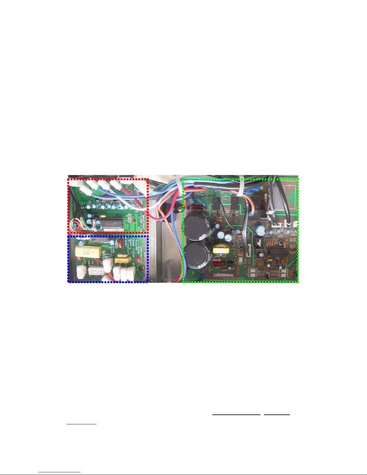
The outdoor circuit is generally divided into three parts, i.e. outdoor power source board, Power
Factor Correction (PFC) board and Intelligent Power Module (IPM). The details are as follows:
PFC board Outdoor power source board
WT/WL-LI Inverter Air Conditioner Model 1 – 1.5P has been developed for four generations.
The 1
st
generation (V1) applies 120° square wave control plan and the all PFC plan is used for
power treatment.
The 2nd generation (V2) remains to apply 120° square wave control plan, but the partial PFC plan
is used for power treatment. This product is never put into batch production.
The 3
rd
generation (V3) applies 180° sine wave plan and partial PFC plan. This model is also few.
The 4
th
generation (V4) remains to apply 180° sine wave plan (including 2P unit), where only
significant adjustment is made to the function architecture. That is, the indoor control plan applied
for the 1
st
and 2nd generation is changed to outdoor control (For details on the function distribution,
please refer to the Control Function Chart below.
The 5
th
generation(V5), the function is same as V4, but the Power source board, PFC board and
IPM board
have already integrated onto one board (All-In-One) for easily installation and
IPM board
3
repairing.
The products 2P and higher are mainly developed for two generations.
The 1
st
generation (VP1) applies NEC 180° sine wave plan and indoor control.
The 2
nd
generation (VP2) applies TI DSP 180° sine wave plan and outdoor control. (Exclusive of
2P unit).
There are derivative models, e.g. full DC inverter unit, inverter floor-standing unit and LC plan.
See Appendix 1 for details.
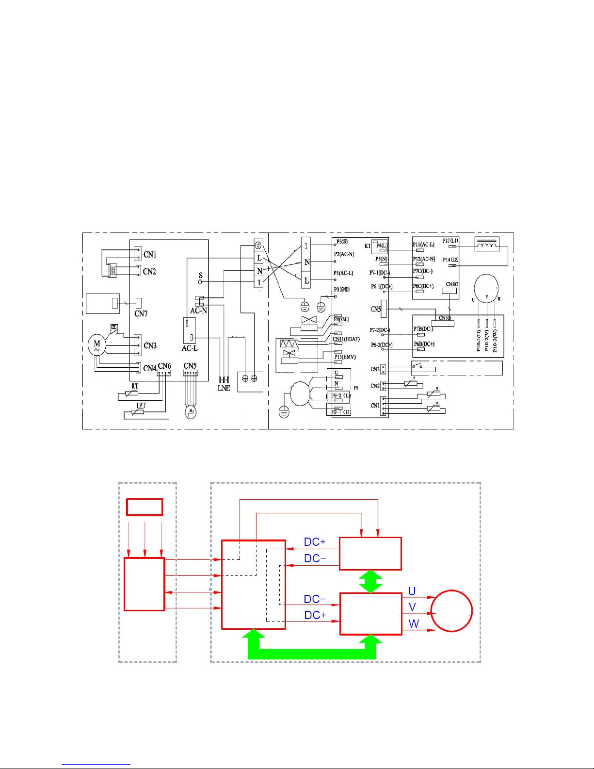
2. Wiring of Inverter AC Unit
3. Current Flow
Power
supply
Live
N
eutral
Ground
Live
N
eutral
Communicati
on wire
Ground
Main
control
board
Indoor
unit
Outdoor
power
source
Live
N
eutral
Outdoor
Unit
PFC board
IPM board
Compressor
Tran sforme r
Display circuit
board
Motor
protector
Fan Motor
Room temperature
sensor
Coil temperature
sensor
Main control
board
Rela
y
Guide louver
moto
r
Y/G
B
rOr
BL
BL
BR
Indoor uni
t
Y/G
Heat exchange
r
Wh
BL
B
r
Y/G
O
r
BL
Y/G
4-way Valve
BL
Electric
Heater
Solenoid
valve
Optional
Y/G
Outdoor uni
t
Fan
motor
O
r
BL
Re
BL
N
ote: There is no LOW FAN for single-speed motor P9-2
B
r
BL
Re
BL
Outdoor power source boar
d
BL
Re
Re
Re
Reactor
Compressor
Re
Wh
BL
Module board
Compressor top protection switch
(Optional)
Exhaust temperature senso
r
Outdoor temperature sensor
Outdoor coil temperature sensor
Port: P9 pair port for dual-speed moto
r
4
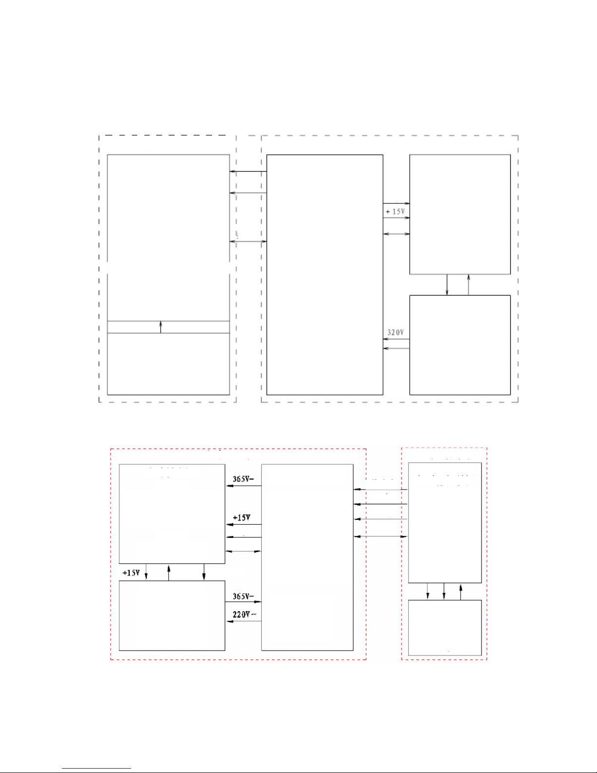
4. Computer Control Function Flow Chart for Inverter AC Unit
1) Outdoor control plan
2) Indoor control plan
Indoor control system
Indoor control board
Communication with outdoor unit
Indoor fan control
Louver motor control
Health assembly control
Temperature detection
Fan speed feedback
Electric heater control
Selection of cool-heat and cool-only
model
Selection of data sheet
Selection of Fahrenheit and
Centigrade temperature
Selection of LED OR without LED
display
Signal input
Display board
Temperature or fault code display
Emergencyl Switch signal input
Remote signal input
Live
N
eutral
Communi
cation
wire
Outdoor control system
Outdoor power source board
Storage of working parameters
Frequency generation
Outdoor temperature detection
Communication with indoor unit
Outdoor fan control
4-way valve control
Outdoor power treatment
Power ON/OFF
Communication with IPM
Fault and compressor state
indication
Switch signal on top of the
compressor
Chassis heating control
Electronic expansion valve control
Pressure switch signal processing
Voltage sampling
Signal
wire
Commu
nication
IPM module
Communication with power
source board
Compressor drive
IPM fault output
PFC control DC power
Outdoor PFC board
AC rectifier
Power factor adjustment
Protection current sampling
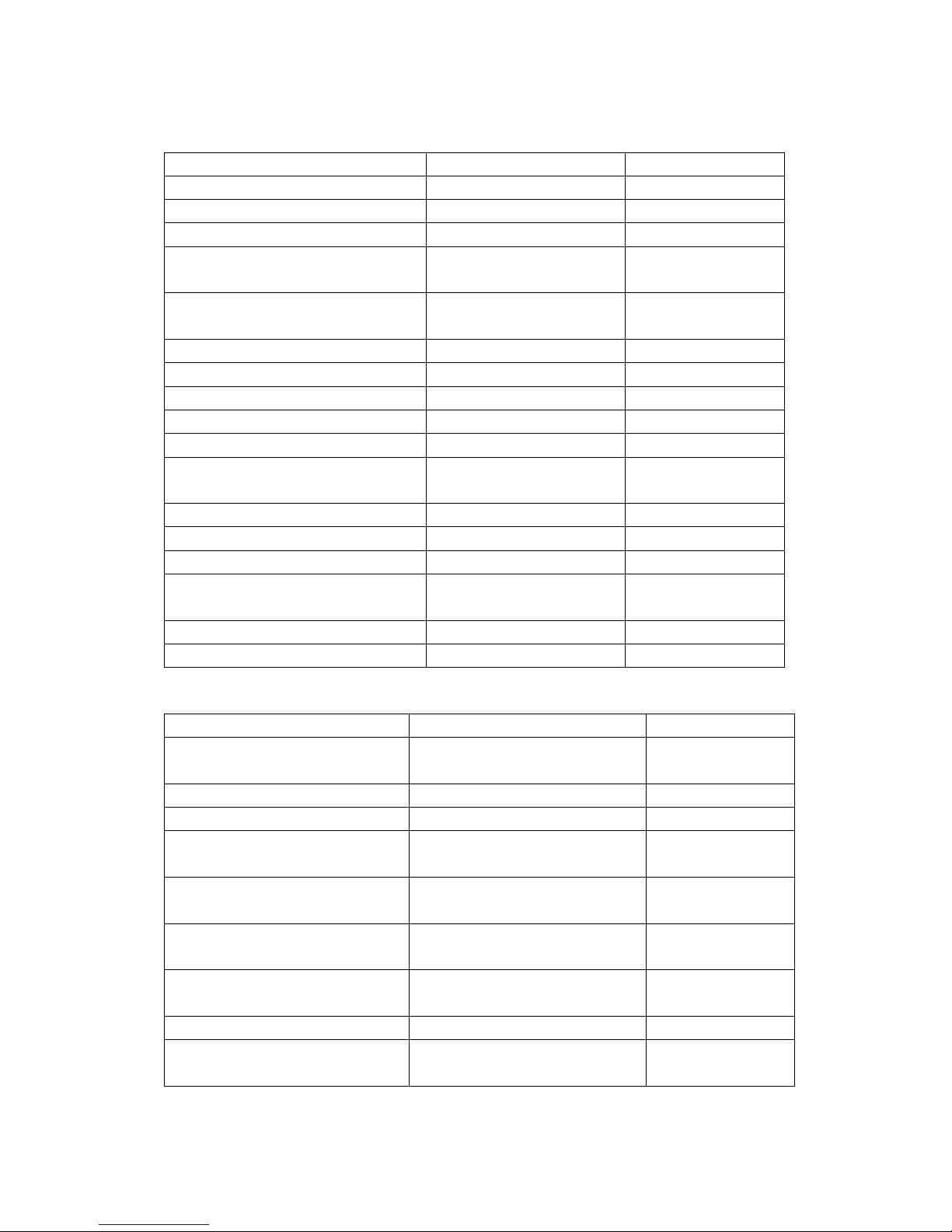
Outdoor control
IPM module
ST72141
Communication with power source
board、PFC control、IPM drive、Current
sampling and processing 、 Voltage
sampling and signal processing 、
Detection of compressor feedback signal
PS21865
Compressor inverter drive
IPM fault signal output
Signal
wire
PFC control
Signal wire
Outdoor PFC board
AC rectifier
Power factor adjustment
Boosting of DC voltage
Protection current sampling
Harmonic inhibition
Outdoor power source
b
oar
d
TMP86F807N
Temperature detection
Communication with indoo
r
unit
Outdoor fan control
4-way valve control
Communication with module
board
Power source indication
Repair key signal processing
Compressor top temperature
protection
BMC processing
AC voltage sampling
DC harmonics
Supply DC power
Ground wire
Communic
ation wire
Communic
ation wire
L wir e
N
wire
Indoor control
Indoor main PCB
TMP86PH46NG
Working frequency control
Indoor fan control
Swing motor control
Temperature detection
Storage of model
p
arameters
Operating signal processing
Outdoor power supply
Audio indication fo
r
operation
Communication with
outdoor unit
Other optional functions
Indoor display panel
Remote signal acceptance
Preset temperature display
Protection and fault display
Key operation
5
5. Protection and Fault Codes
Fault Code
Fault Type
Function Indicator (flash) Digital LED display
Indoor/outdoor communication fault RUN & TIMER: Blink E0
outdoor communication fault RUN & TIMER: Blink EC
Room temperature sensor (IRT) RUN-1/8 sec. E1
Indoor pipe (coil) temperature sensor
(IPT)
RUN-2/8 sec. E2
Outdoor pipe (coil) temperature sensor
(OPT)
RUN-3/8 sec. E3
System abnormal RUN-4/8 sec. E4
Model configuration wrong RUN-5/8 sec. E5
Indoor fan motor fault RUN-6/8 sec. E6
Outdoor temperature sensor RUN-7/8 sec. E7
Exhaust temperature sensor RUN-8/8 sec. E8
Intelligent power module of drive and
module fault
RUN-9/8 sec. E9
Outdoor fan motor fault (DC Motor) RUN-10/8 sec. EF
Current sensor fault RUN-11/8 sec. EA
EEPROM fault RUN-12/8 sec. EE
Temperature switch fault (on top of the
compressor)
RUN-13/8 sec. EP
Voltage sensor fault RUN-14/8 sec. EU
Intake temperature sensor RUN-15/8 sec. EH
Protection Code
Protection Type Function Indicator (flash)
Digital LED display
Overvoltage /
undervoltage protection
RUN: Blink; TIMER: 1 blink /8 sec P1
Overcurrent protection RUN: Blink; TIMER: 2 blink /8 sec P2
Exhaust overtemperature protection RUN: Blink; TIMER: 4 blink /8 sec P4
Subcooling protection
under cooling mode
RUN: Bright; TIMER: 5 blink /8
sec
P5
Overheating protection
under cooling mode
RUN: Bright; TIMER: 6 blink /8
sec
P6
Overheating protection
under heating mode
RUN: Bright; TIMER: 7 blink /8
sec
P7
Outdoor overtemperature
/ undertemperature protection
RUN: Bright; TIMER: 8 blink /8
sec
P8
Drive protection (software control ) RUN: Blink; TIMER: 9 blink /8 sec P9
Module protection (hardware
control)
RUN: Blink; TIMER: 10 blink /8
sec
P0

6
Display on outdoor power source board: The indicator alerts the fault in a cycle as such that it is
bright for 0.5 seconds, dark for 0.5 seconds, blinks “n” times and then dark for 3 seconds.
Blink
times(n)
Fault Message
Blink
times(n)
Fault Message
1 IPM protection 18
Short-circuit / open-circuit fault of
intake temperature sensor
2 Overvoltage / undervoltage 19 Outdoor EEPROM fault
3 Overcurrent 20 Outdoor fan motor protection
4 Exhaust overtemperature protection 21 Indoor fan motor protection
5
Outdoor coil overtemperature
protection
6 Drive fault and protection (V1,VP1) 23 System in shortage of Freon
7
Communication fault with indoor
unit
24 Model configuration wrong
8
Compressor overheat fault
(compressor top switch)
25 Indoor sensor fault
9
Short-circuit / open-circuit fault of
outdoor temperature sensor
26 Indoor coil sensor fault
10
Short circuit / open-circuit fault of
outdoor heat exchanger temperature
sensor
27 Indoor EEPROM fault
11
Short-circuit / open-circuit fault of
exhaust temperature sensor
28 Indoor fan motor fault
12 Voltage sensor fault 30 drive fault(V4、VP2)
13 Current sensor fault 31
Outdoor environmental
overtemperature /
undertemperature protection
14 IPM fault 32 Indoor coil deforst prevention
15
communication fault between power
source board and intelligent power
module
33 Indoor coil overheating protection
16
No feedback from DC fan
motor(outdoor unit)
17 Defrost state
7
Display on V5 All-in-one board
Blink
Counts
Fault Message
Blink
Counts
Fault Message
1 IPM fault 2
Short-circuit / open-circuit fault of
outdoor temperature sensor
3 Outdoor coil sensor fault 4 Absorption temperature sensor fault
5 Exhaust temperature sensor fault 6 Current sensor fault
7 Compressor drive fault 8 Compressor drive protection
9 Outdoor overheat protection 10 IPM protection
11 AC overcurrent protection 12 Exhaust Temperature Protection
13 Compressor top temperature protection 14 Exhaust Overtemperature Protection
15 Voltage protection 16 Exhaust underpressure protection
17 Exhaust Overpressure Protection 18 Indoor antifreeze protection
19 Indoor overheat protection 20 Indoor / outdoor communication fault
21 Outdoor EEPROM fault 22
Outdoor ambient overtemperature
protection
23 Outdoor DC fan fault 24 Outdoor coil overheat protection
25 Model configuration wrong 26 Indoor fan fault
27 Reserved 28 Reserved
29 Reserved 30 Reserved
V5 All-in-one board
8
II. Troubleshooting
1. According to the fault code
(1) Display E1 or E2:
Symptom Display E1 or E2
Cause
Room temperature sensor (IRT) and Indoor
pipe (coil) temperature sensor (IPT) fault
S/N Inspections How to Solve Remarks
1 Contact between indoor
temperature sensor CN6 (RT, IPT)
and slot
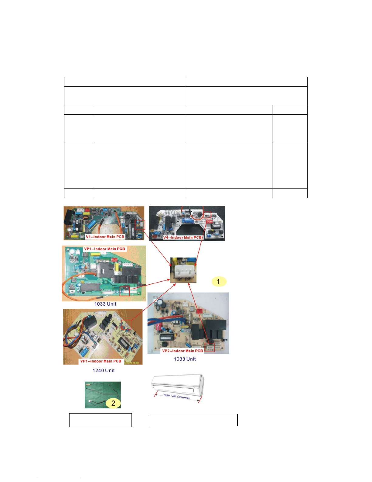
Insert again if loose. Photo 1
2 Measure the resistance on the two
ends of indoor temperature sensor:
(25 / 5KΩ). For other resistance, ℃
please refer to the Temperature –
Resistance Sheet (Appendix 1).
Replace the temperature sensor
if the resistance is incurred to
drift, open or short circuiting.
Photo 2
3 If the above testing is normal Replace the indoor control board
Position and marking of temperature sensors
CN6 (RT, IPT) on indoor control board
1033 Unit and 1240 Unit
indicate the dimensions of indoor unit.
Measure the resistance of
indo or temperature sensor
9
(2) Display E6
Symptom Display E6
Cause Indoor fan motor fault
S/N Inspections How to Solve Remarks
1
Check the indoor cross-flow fan
blade
If the fan does not run, readjust
the fan position until it can run
smoothly.
2
If the motor insert (CN3, CN4) on
indoor main PCB is in good contact
with the slot
Insert again if loose.
Red-line
part
3 Startup capacitance value
Capacitance incorrect. Replace
with a new capacitor.
Yellow-line
part
4 The above inspections are normal Replace the indoor main PCB
10
(3) Display E3, E7, E8
Symptom Display E3, E7, E8
Cause
Outdoor pipe (coil) temperature sensor and
outdoor temperature sensor and exhaust
temperature sensor fault
S/N Inspections How to Solve Remarks
1
If the temperature sensor on
outdoor power source board is in
good contact with the slot (CN1,
CN2)
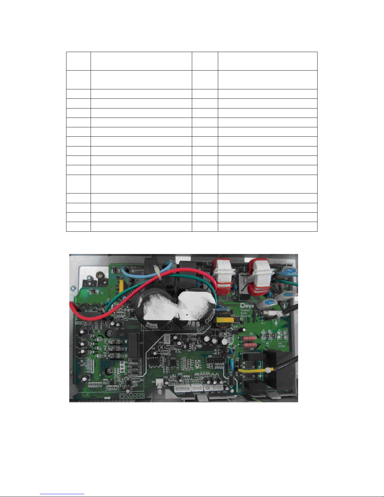
Insert again if loose. Photo 3
2
Measure the resistance on the two ends of
outdoor temperature sensor:
Resistance of CN1 terminal sensor –
(25 / 5KΩ). For other resistance, please ℃
refer to the Temperature – Resistance
Sheet. Resistance of CN2 terminal sensor
– (25 / 20KΩ). For other resistance, ℃
please refer to the Exhaust Temperature
Sensor Resistance Sheet.
Replace the temperature sensor
if the resistance is incurred to
drift, open or short circuiting.
Photo 4
3 If the above testing is normal Outdoor power source board
Position and marking of
temperature sensors (CN1, CN2) on
outdoor power source board
CN1 terminal sensorCN2 terminal senso
r

11
(4) Display E4
Symptom Display E4
Cause
System abnormal: Let the compressor run for 5
minutes. If the indoor coil temperature cannot
be 2 lower than that before the compressor is ℃
started (2 higher for heating mode), it can be ℃
judged that the system is abnormal.
S/N Inspections How to Solve Remarks
1
Check the high-pressure and
low-pressure valves.
If not open, open again to ensure
the system circulation is smooth.
Photo 5
2
Check the system refrigerant (Start
and run under cooling mode. When
the compressor is started, check the
outlet temperature for its change. If
the change is not obvious after 5
minutes)
The system is in shortage of
refrigerant. Test with pressure
gauge, check the leakage point
and recharge the refrigerant.
Photo 6
3
Check the evaporator coil
temperature sensor (25 /5KΩ). ℃
For other resistance, please refer to
the Temperature – Resistance
Sheet.
Replace the temperature sensor
if the resistance is incurred to
drift, open or short circuiting.
Photo 7
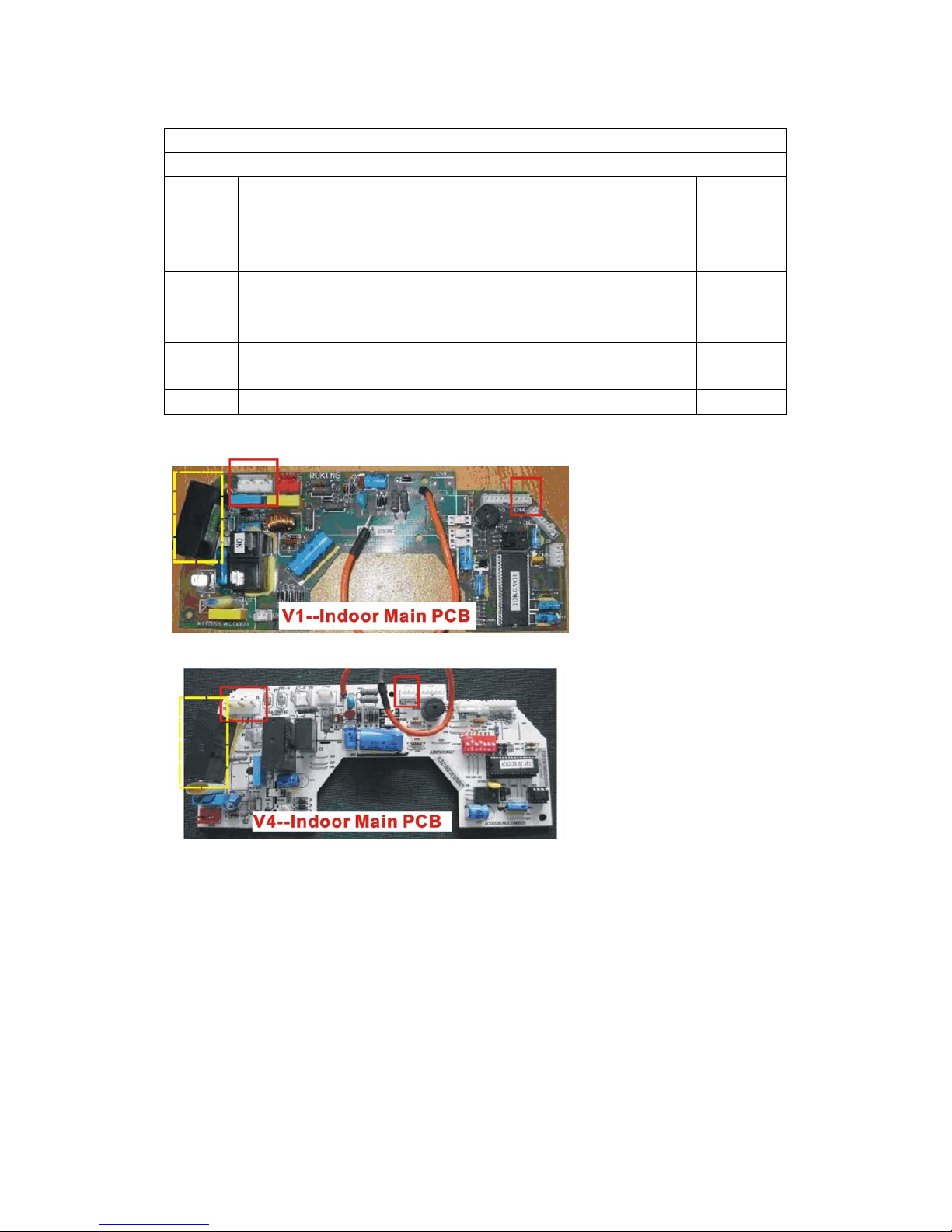
1. The flow might be uneven for
indoor system. Short circuit JP4
jumper of the indoor control
board to shield this protection
function (V1 – Indoor Main
PCB).
Photo 8
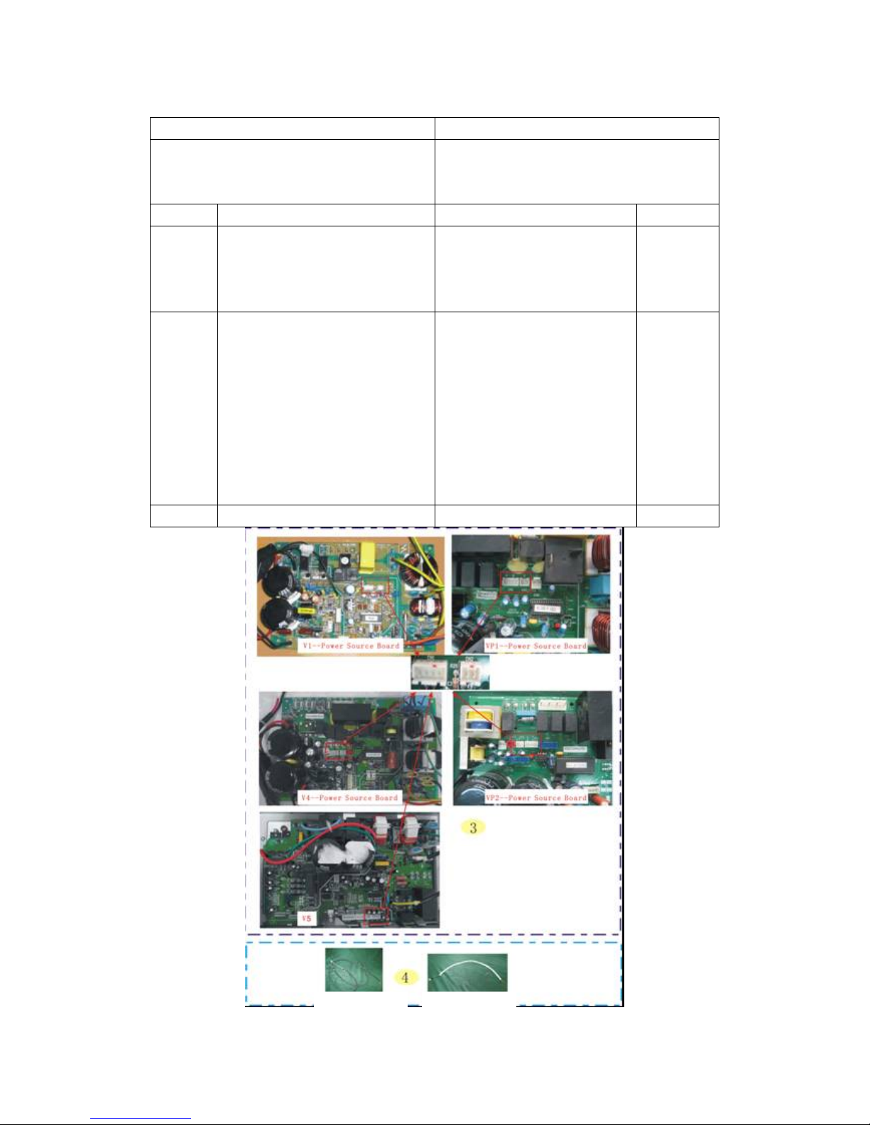
2. The flow might be uneven for
indoor system. Dial the JP4
switch of the outdoor power
source board to position “1” to
shield this protection function
(V4 – Power Source Board).
Photo 9
4 The above inspections are normal
Replace the indoor main PCB
if the problem cannot be solved
by using the above methods.
 Loading...