

Pioneer YN020GMFI22M2D, YN030GMFI22M3D, YN040GMFI22M4D, YN050GMFI22M5D Installation Manual
DC INVERTER TWO, THREE, FOUR AND FIVE ZONE MULTI SPLIT-TYPE AIR CONDITIONER HEAT PUMP
Installation Manual
IMPORTANT NOTE:
•
Read this manual carefully before
installing or operating your new air
conditioning unit. Make sure to save
this manual for future reference.
•
This manual only describes the information
for the outdoor unit. For matched indoor units
refer to the user’s manual provided with the indoor unit.
Copyright 2016 Parker Davis HVAC International Inc. All rights reserved.
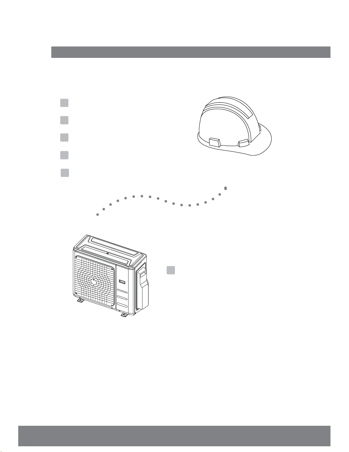
Table of Contents
Installation Manual
1
Accessories .................................................... 04
2
Safety Precautions ..................................... 05
3
Installation Overview ............................... 06
4
Installation Diagram
5
Specications
................................ 07
.............................................. 08
6
Outdoor Unit Installation ......................... 09
a. Outdoor Unit Installation Instructions ..... 09
b. Drain Joint Installation ................................ 11
c. Notes on Drilling Hole on Wall ................... 11
d. When Selecting a 24K Indoor Unit. ......... 11
Refrigerant Piping Connection ............... 12
7
L1 L2
9
Air Evacuation
.......................................... 20
8
Wiring ................................................. 14
a. Outdoor Unit Wiring ................... 14
b. Wiring Figure ................................ 16
MC MC
a. Evacuation Instructions ......................... 20
b. Note on Adding Refrigerant ............... 21
10
Test Run.......................................................22
11
Function of Automatic Wiring/Piping Correction......23
Page 3
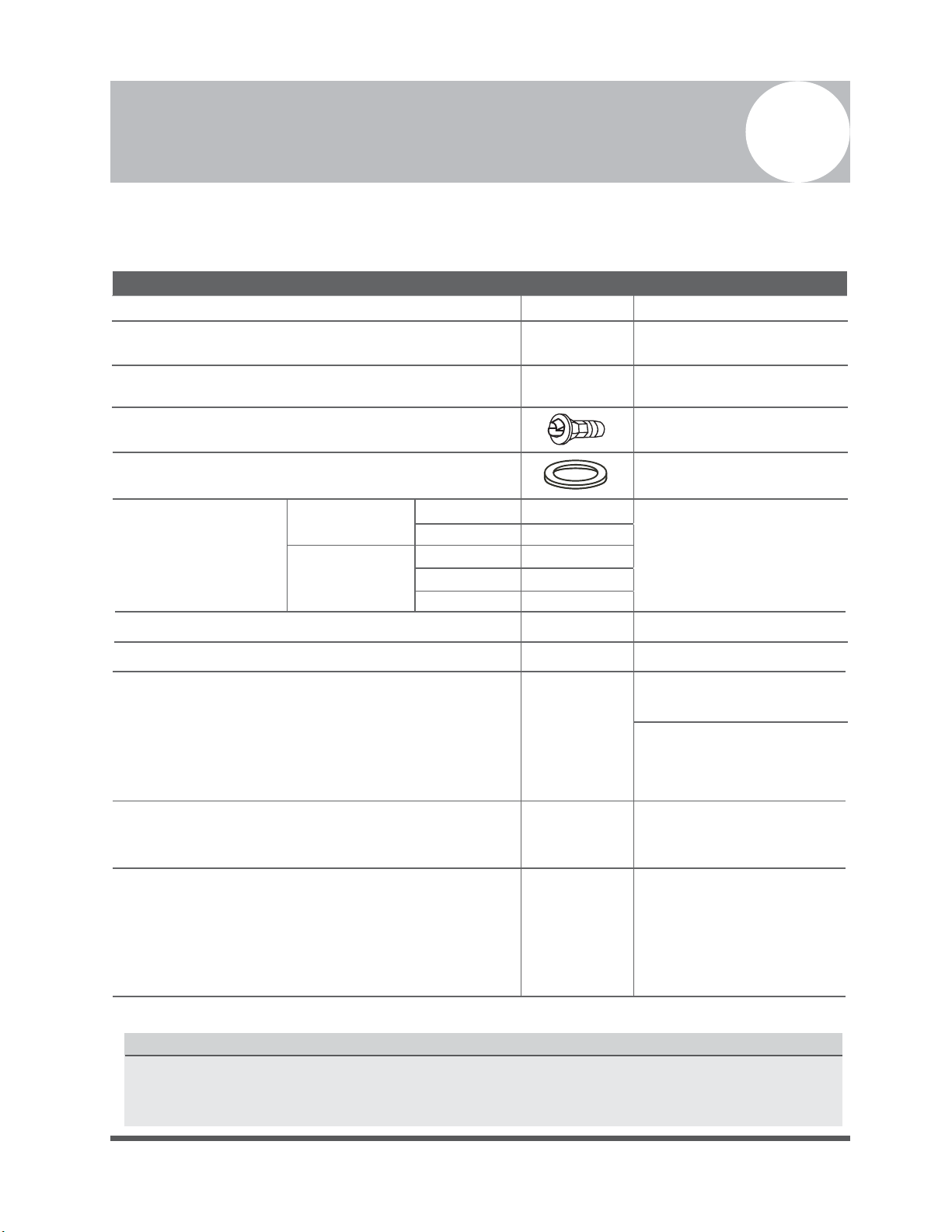
Accessories
1
The air conditioning system comes with the following accessories. Use all of the installation parts and
accessories to install the air conditioner. Improper installation may result in water leakage, electrical
shock and fire, or cause the equipment failure.
Name Shape Quantity
Installation Plate
Plastic Expansion Anchor
1
5-8
(depending on models)
Self-tapping Screw A ST3.9X25
Drain joint (some models)
Seal ring (some models)
Connecting
pipe
Assembly
Valve connector adapter (Packed with the indoor unit
or outdoor unit, depending on models )
(NOTE: Pipe size dier from appliance to appliance.
To meet dierent pipe size requirement, sometimes
the pipe connections need the brass adapters
to attach to the valves of the outdoor unit)
Magnetic ring
(Insert it over the connective cable between
indoor unit and outdoor unit during installation.)
Cord protection rubber ller ring
(If the cord clamp can not properly fasten the cord for
the small cord diameters, please use the cord
protection rubber ller ring (supplied with
accessories) to wrap on the cord, then tighten under
the cord clamp.)
Liquid side
Gas side
Owner’s manual
Installation manual
Ø6.35
Ø9.52
Ø9.52
Ø12.7
Ø15.9
5-8
(depending on models)
1
1
Size depends on indoor unit
Consult the technician
for the proper size.
1
1
Optional part
(one piece/one indoor unit)
Optional part
(1-5 pieces for outdoor
unit, depending on models)
Optional part
(one piece/one cable)
1
(on some models)
Optional Accessories
There are two types of remote controllers: Wired and Wireless.
Select a remote controller according to customers needs and install in an appropriate place.
Refer to catalogues and technical literature for selecting a suitable remote controller.
Page 4

Safety Precautions
Failure to observe a warning may result in death. The appliance must be installed in
accordance with national and local codes and regulations.
Failure to observe a caution may result in injury or equipment damage.
2
Read Safety Precautions Before Installation
Incorrect installation due to ignored instructions can cause serious damage or injury.
The seriousness of potential damage or injuries is classified as either a WARNING or CAUTION.
WARNING
CAUTION
WARNING
• Carefully read the Safety Precautions before installation.
• In certain functional environments, such as kitchens, server rooms, etc., the use of air-conditioning
units specically designed for this purpose is highly recommended.
• Only trained and certied technicians should install, repair and service this air
conditioning unit. This is a complex system for a DIY person without proper tools or training.
Improper installation may result in electrical shock, short circuit, leaks, fire or other damage to
the equipment and personal property.
• Strictly follow the installation instructions set forth in this manual.
Improper installation may result in electrical shock, short circuit, leaks, fire or other damage to
the equipment.
• Before you install the unit, consider strong winds, earthquakes and other perils that might aect
your unit and locate it accordingly. Failure to do so could cause the equipment to fail.
• After installation, ensure there are no refrigerant leaks and that the unit is operating properly.
Refrigerant is both toxic and flammable and carries a serious health and safety risk.
Note about Fluorinated Gasses
1. This air-conditioning unit contains fluorinated gasses. For specific information on the type of gas
and the amount, please refer to the relevant label on the unit itself.
2. Installation, service, maintenance and repair of this unit must be performed by a certified
technician.
3. Product uninstallation and recycling must be performed by a certified technician.
4. If the system has a leak-detection system installed, it must be checked for leaks at least every 12
months.
5.
When the unit is checked for leaks, proper record-keeping of all checks is strongly recommended.
Page 5
Unit Installation
Overview
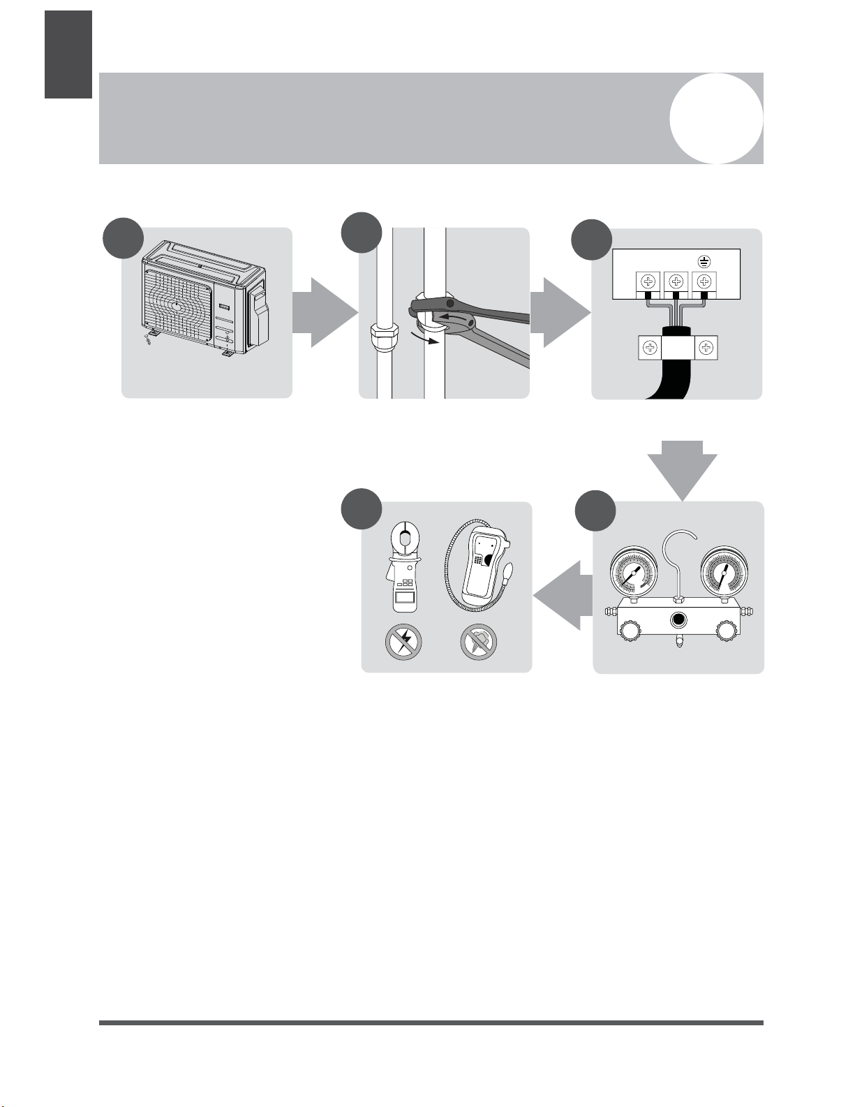
Installation Overview
3
INSTALLATION ORDER
1
Install the outdoor unit
(Page 9)
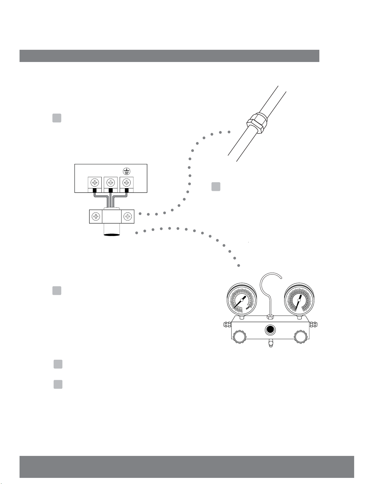
2
Connect the refrigerant pipes
(Page 12)
5
3
L1 L2
Connect the wires
(Page 14)
4
MC MC
Page 6
Perform a test run
(Page 22)
Evacuate the refrigeration
system
(Page 20)

Installation Diagram
Installation Diagram
4
Installation
Diagram
2 ZONE
3 ZONE
4 ZONE
5 ZONE
Safety Precautions
CAUTION
• This illustration is for explanation purposes
only. The actual shape of your air
condtioner may be slightly dierent.
•
Copper lines must be insulated individually
and independently
Fig. 4.1
CAUTION
• Use a stud nder to locate studs to prevent
unnecessary damage to the wall.
A minimum pipe run of 3m (10’) is needed
•
to minimise vibration & excessive noise.
•
Area around the outdoor unit should be
free from obstructions.
Page 7
Specications
Table 5.1
Indoor units that can be used in
Specications
combination
Compressor stop/start frequency Stop time 3 min or more
Power source voltage
Number of connected
units
voltage uctuation within ±10% of rated voltage
voltage drop during start within ±15% of rated voltage
interval unbalance within ±3% of rated voltage
1-5 units
5
Outdoor Unit
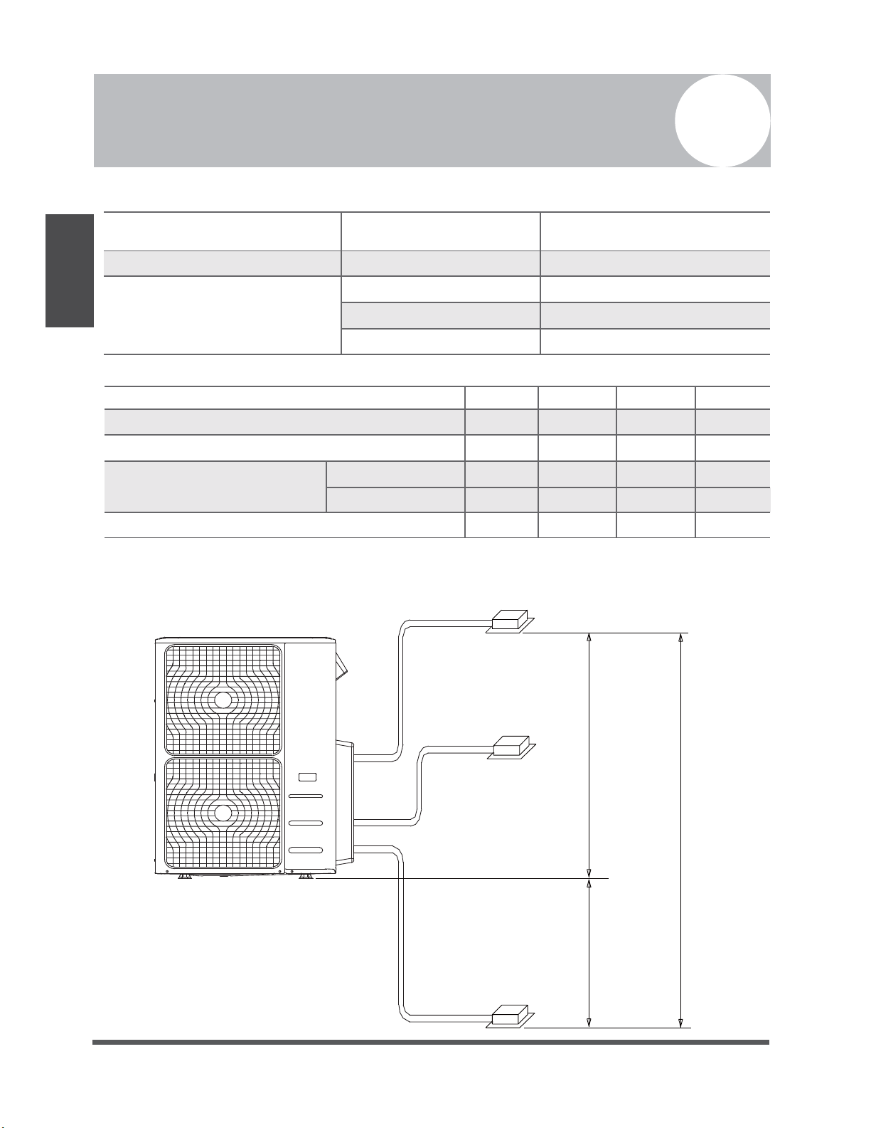
Table 5.2
2 Zone 3 Zone
Max. length for all rooms 30/100 45/150
Max. length for one indoor unit 20/65 25/80
Max. height dierent between
indoor and outdoor unit
Max. height dierent between indoor units
When installing multiple indoor units to a single outdoor unit, ensure that the length of the refrigerant
pipe and the drop height between the indoor and outdoor units meets the following requirements:
Outdoor unit
OU higher than IU
OU lower than IU 15/50 15/50
10/33 10/33
10/33 10/33
Indoor unit
Max.Height dierence
Indoor unit
4 Zone 5 Zone
60/200 75/250
30/100 30/100
10/33 10/33
15/50 15/50
10/33 10/33
15m(50ft)
Unit: m/ft.
Page 8
15m(50ft)
10m(33ft)
Indoor unit
Outdoor Unit Installation
Outdoor Unit Installation Instructions
Step 1: Select installation location.
The outdoor unit should be installed in the
location that meets the following requirements:
√
Place the outdoor unit as close to the indoor
units as possible.
√
Ensure that there is enough room for
installation and maintenance.
√
The air inlet and outlet must not be
obstructed or exposed to strong wind.
√
Ensure the location of the unit will not be
subject to snowdrifts, accumulation of leaves
or other seasonal debris. If possible, locate
the unit under an awning. Ensure the awning
does not obstruct the airflow.
√
The installation area must be dry and well
ventilated.
√
There must be enough room to install the
connecting pipes and cables and to access
them for maintenance.
6
√
The area must be free of combustible gases
and chemicals.
√
The pipe length between the outdoor and
indoor unit may not exceed the maximum
allowable pipe length.
√
If possible, install the unit away from where
it can be exposed to direct sunlight.
√
If possible, make sure the unit is located far
away from your neighbors’ property so that
the noise from the unit will not disturb them.
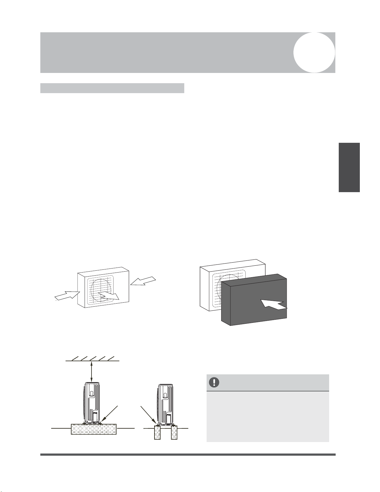
√
If the location is exposed to strong winds (for
example: near a seaside), the unit must be
placed against the wall to shelter it from the
wind. If necessary, use an awning.
(See Fig. 6.1 & 6.2)
√
Install the indoor and outdoor units, cables
and wires at least 1 meter from televisions or
radios to prevent static or image distortion.
Depending on the radio waves, a 1 meter
distance may not be enough to eliminate all
interference.
Outdoor Unit
Installation
Strong wind
trong wind
Fig. 6.1
Step 2: Install outdoor unit.
Fix the outdoor unit with anchor bolts (M10)
>60cm / 23.6”
Fix with bolts
Fig. 6.3
Strong wind
Fig. 6.2
CAUTION
• Be sure to remove any obstacles that
may block air circulation.
• Make sure you refer to Length
Specifications to ensure there is
enough room for installation and
maintenance.
Page 9
 Loading...