

Pioneer CB009GMFILCFHD, RB009GMFILCFHD, FB009GMFILCFHD, CB012GMFILCFHD, RB012GMFILCFHD SERVICE MANUAL
...Page 1
LIGHT COMMERCIAL SPLIT SYSTEMS
3D DC INVERTER HEAT PUMP
SERVICE MANUAL
ALL RIGHTS RESERVED. PARKER DAVIS HVAC INTERNATIONAL, INC., DORAL, FL 33172 USA
Phone: (800) 243-0340 www.highseer.com
RevisionA:1605,Contentupdated.
Table of Contents
1. Precaution
2. Part Names And Functions
3. Dimension
4. Service space
5. Refrigerant Cycle Diagram
6. Wiring Diagram
7. Static Pressure
8. Electric Characteristics
9. Sound Level
10. Accessories
11. The Specification of Power
12. Installation Details
13. Operation Characteristics
14. Electronic Function
15. Solar Panel
16. Troubleshooting
17. Disassembly Instructions
ModelNumbers:
IndoorUnitModelNumbers:
CeilingCassette ConcealedDucted Floor,Ceiling,LowWall
CB009GMFILCFHD RB009GMFILCFHD FB009GMFILCFHD
CB012GMFILCFHD RB012GMFILCFHD FB012GMFILCFHD
CB018GMFILCFHD RB018GMFILCFHD UB018GMFILCFHD
CB024GMFILCFHD RB024GMFILCFHD UB024GMFILCFHD
CB036GMFILCFHD RB036GMFILCFHD UB036GMFILCFHD
CB048GMFILCFHD RB048GMFILCFHD UB048GMFILCFHD
OutdoorUnit:
StandardCommunicationCircuitModels:
YN009GMFI22RPD YN012GMFI22RPD YN018GMFI22RPD
YN024GMFI22RPD
RS‐485CommunicationCircuitModels:
YN036GMFI17RUD YN038GMFI17RUD
Single Zone
WARN ING
Installation MUST conform with local building codes or, in the absence of local codes, with the National
Electrical Code NFPA70/ANSI C1-1993 or current edition and Canadian Electrical Code Part1 CSA
C.22.1.
The information contained in the manual is intended for use by a qualified service technician familiar
with safety procedures and equipped with the proper tools and test instruments
Installation or repairs made by unqualified persons can result in hazards to you and others.
Failure to carefully read and follow all instructions in this manual can result in equipment malfunction,
property damage, personal injury and/or death.
This service is only for service engineer to use.
Page 2

CONTENTS
1. Precaution .................................................................................................................................................. 1
1.1 Safety Precaution ....................................................................................................................... 1
1.2 Warning ...................................................................................................................................... 1
2. Part Names and Features .......................................................................................................................... 4
2.1 Model Names of Indoor/Outdoor units ........................................................................................ 4
2.2 Part names of Indoor/Outdoor units ............................................................................................ 5
2.3 Features ..................................................................................................................................... 9
3. Dimension ................................................................................................................................................ 18
3.1 Indoor Unit ................................................................................................................................ 18
3.2 Outdoor Unit ............................................................................................................................. 23
4. Service Space .......................................................................................................................................... 24
4.1 Indoor Unit ................................................................................................................................ 24
4.2 Outdoor Unit ............................................................................................................................. 26
5. Refrigerant Cycle Diagram ...................................................................................................................... 27
6. Wiring Diagram ........................................................................................................................................ 28
6.1 Indoor Unit ................................................................................................................................ 28
6.2 Outdoor Unit ............................................................................................................................. 34
7. Fan Curves ............................................................................................................................................... 40
8 Electric Characteristics ............................................................................................................................ 47
9 Sound Level .............................................................................................................................................. 48
9.1 Indoor unit ................................................................................................................................ 48
9.2 Outdoor unit .............................................................................................................................. 51
10 Accessories ............................................................................................................................................ 52
11 The Specification of Power .................................................................................................................... 54
12 Installation Details .................................................................................................................................. 56
12.1 Location selection ............................................................................................................... 56
12.2 Indoor unit installation ......................................................................................................... 56
12.3 Outdoor unit installation ...................................................................................................... 61
12.4 Refrigerant pipe installation ................................................................................................ 62
12.5 Drainage pipe installation .................................................................................................... 66
12.6 Vacuum Drying and Leakage Checking .............................................................................. 69
12.7 Additional refrigerant charge ............................................................................................... 70
12.8 Engineering of insulation ..................................................................................................... 71
12.9 Engineering of electrical wiring ........................................................................................... 72
12.10 Test operation .................................................................................................................. 72
13. Operation Characteristics ..................................................................................................................... 74
14. Electronic Function ............................................................................................................................... 75
14.1 Abbreviation ............................................................................................................................ 75
14.2 Display function ...................................................................................................................... 75
14.3 Main Protection ....................................................................................................................... 75
14.4 Operation Modes and Functions............................................................................................. 76
16. Troubleshooting .................................................................................................................................... 82
16.1 Indoor Unit Error Display ........................................................................................................ 83
16.2 Outdoor unit error display ....................................................................................................... 84
Page 3

For 9K-24K outdoor unit: ................................................................................................................ 84
For 36K-48K Outdoor Unit .............................................................................................................. 85
Outdoor check function ................................................................................................................... 86
16.3 Diagnosis and Solution ........................................................................................................... 88
16.4 Main parts check .................................................................................................................. 102
17. Disassembly Instructions ................................................................................................................... 109
17.1 Indoor unit ............................................................................................................................ 109
17.2 Outdoor unit .......................................................................................................................... 126
Page 4

1. Precaution
1.1 Safety Precaution
To prevent injury to the user or other
people and property damage, the following
instructions must be followed.
Incorrect operation due to ignoring
instruction will cause harm or damage.
Before service the unit, be sure to
read this service manual at first.
1.2 Warning
Installation
Do not use a defective or underrated
circuit breaker. Use this appliance on a
dedicated circuit.
There is risk of fire or electric shock.
For electrical work, contact the dealer,
seller, a qualified electrician, or an
authorized service center.
Do not disassemble or repair the product,
there is risk of fire or electric shock.
Always ground the product.
There is risk of fire or electric shock.
Install the panel and the cover of
control box securely.
There is risk of fire of electric shock.
Always install a dedicated circuit and
breaker.
Improper wiring or installation may cause
electric shock.
Use the correctly rated breaker of
fuse.
There is risk of fire or electric shock.
Do not modify or extend the power
cable.
There is risk of fire or electric shock.
Do not install, remove, or reinstall the
unit by yourself (customer).
There is risk of fire, electric shock, explosion,
or injury.
Be caution when unpacking and
installing the product.
Sharp edges could cause injury, be especially
careful of the case edges and the fins on the
condenser and evaporator.
For installation, always contact the
dealer or an authorized service center.
Do not install the product on a
defective installation stand.
Be sure the installation area does not
deteriorate with age.
If the base collapses, the air conditioner could
fall with it, causing property damage, product
failure, and personal injury.
Do not let the air conditioner run for a
long time when the humidity is very high
and a door or a window is left open.
Take care to ensure that power cable
could not be pulled out or damaged during
operation.
There is risk of fire or electric shock.
Do not place anything on the power
cable.
There is risk of fire or electric shock.
Do not plug or unplug the power
supply plug during operation.
There is risk of fire or electric shock.
Do not touch (operation) the product
with wet hands.
Do not place a heater or other
appliance near the power cable.
There is risk of fire and electric shock.
Do not allow water to run into
electrical parts.
It may cause fire, failure of the product, or
electric shock.
Do not store or use flammable gas or
combustible near the product.
There is risk of fire or failure of product.
Do not use the product in a tightly
closed space for a long time.
Oxygen deficiency could occur.
When flammable gas leaks, turn off
the gas and open a window for ventilation
before turn the product on.
1
Page 5

If strange sounds or smoke comes
from product, turn the breaker off or
disconnect the power supply cable.
There is risk of electric shock or fire.
Stop operation and close the window
in storm or hurricane. If possible, remove
the product from the window before the
hurricane arrives.
There is risk of property damage, failure of
product, or electric shock.
Do not open the inlet grill of the
product during operation. (Do not touch the
electrostatic filter, if the unit is so equipped.)
There is risk of physical injury, electric shock,
or product failure.
When the product is soaked, contact
an authorized service center.
There is risk of fire or electric shock.
Be caution that water could not enter
the product.
There is risk of fire, electric shock, or product
damage.
Ventilate the product from time to
time when operating it together with a stove
etc.
There is risk of fire or electric shock.
Turn the main power off when
cleaning or maintaining the product.
There is risk of electric shock.
When the product is not be used for a
long time, disconnect the power supply plug
or turn off the breaker.
There is risk of product damage or failure, or
unintended operation.
Take care to ensure that nobody
could step on or fall onto the outdoor unit.
This could result in personal injury and
product damage.
CAUTION
Always check for gas (refrigerant)
leakage after installation or repair of
product.
Low refrigerant levels may cause failure of
product.
Install the drain hose to ensure that
water is drained away properly.
A bad connection may cause water leakage.
Keep level even when installing the
product.
It can avoid vibration of water leakage.
Do not install the product where the
noise or hot air from the outdoor unit could
damage the neighborhoods.
It may cause a problem for your neighbors.
Use two or more people to lift and
transport the product.
Do not install the product where it will
be exposed to sea wind (salt spray) directly.
It may cause corrosion on the product.
Corrosion, particularly on the condenser and
evaporator fins, could cause product
malfunction or inefficient operation.
Operational
Do not expose the skin directly to
cool air for long time. (Do not sit in the
draft).
Do not use the product for special
purposes, such as preserving foods, works
of art etc. It is a consumer air conditioner,
not a precision refrigerant system.
There is risk of damage or loss of property.
Do not block the inlet or outlet of air
flow.
Use a soft cloth to clean. Do not use
harsh detergents, solvents, etc.
There is risk of fire, electric shock, or damage
to the plastic parts of the product.
Do not touch the metal parts of the
product when removing the air filter. They
are very sharp.
Do not step on or put anything on the
product. (outdoor units)
Always insert the filter securely.
Clean the filter every two weeks or more
often if necessary.
A dirty filter reduces the efficiency of the air
conditioner and could cause product
malfunction or damage.
2
Page 6

Do not insert hands or other objects
through air inlet or outlet while the product
is operated.
Do not drink the water drained from
the product.
Use a firm stool or ladder when
cleaning or maintaining the product.
Be careful and avoid personal injury.
Replace the all batteries in the remote
control with new ones of the same type. Do
not mix old and new batteries or different
types of batteries.
There is risk of fire or explosion.
Do not recharge or disassemble the
batteries. Do not dispose of batteries in a
fire.
They may burn of explode.
If the liquid from the batteries gets
onto your skin or clothes, wash it well with
clean water. Do not use the remote of the
batteries have leaked.
3
Page 7
2. Part Names and Features
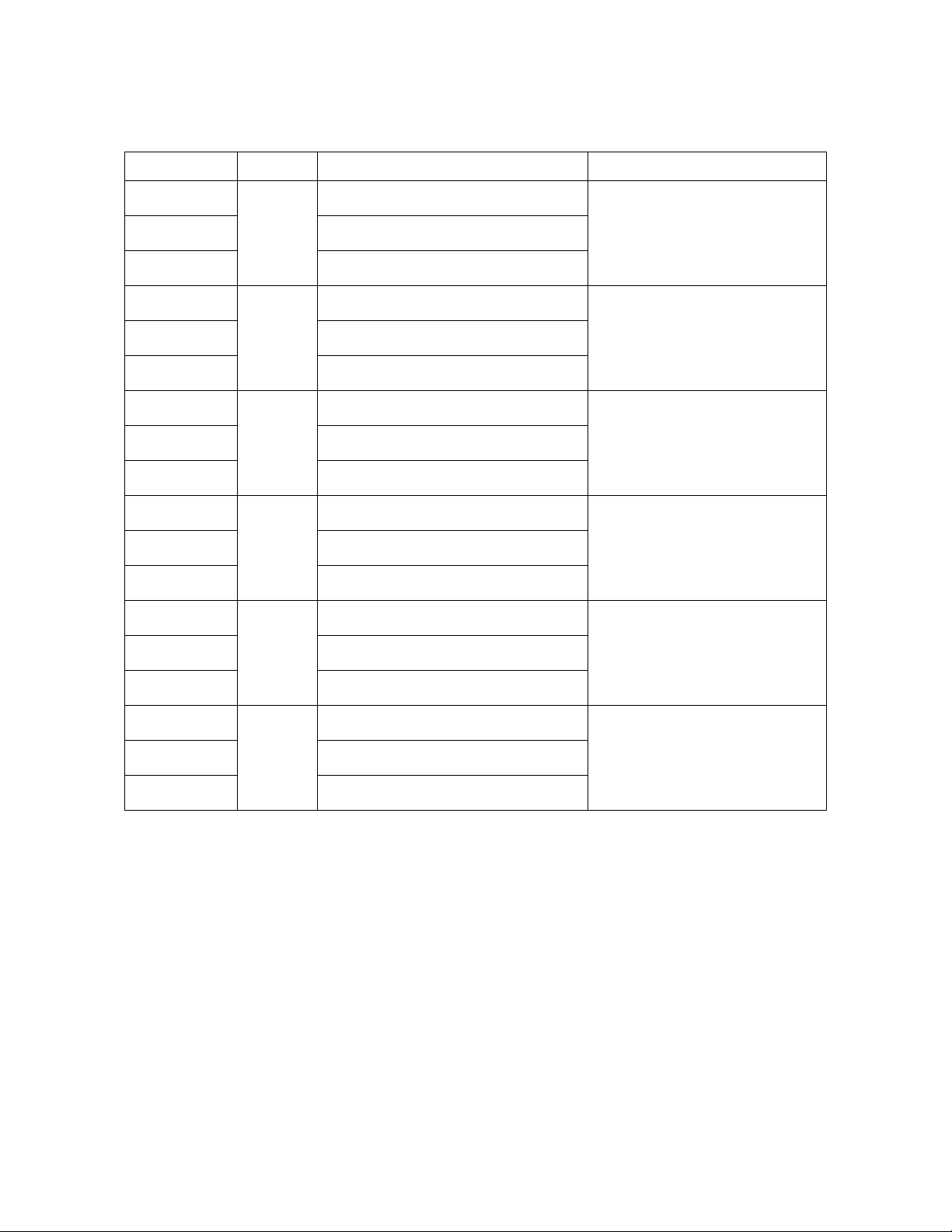
2.1 Model Names of Indoor/Outdoor units
Series Capacity Indoor units
Outdoor units
Cassette
Duct
Console
Cassette
Duct
Console
Cassette
Duct
Floor Ceiling
Cassette
Duct
Floor Ceiling
Cassette
9K
12K
18K
24K
CB009GMFILCFHD
RB009GMFILCFHD
FB009GMFILCFHD
CB012GMFILCFHD
RB012GMFILCFHD
FB012GMFILCFHD
CB018GMFILCFHD
RB018GMFILCFHD
UB018GMFILCFHD
CB024GMFILCFHD
RB024GMFILCFHD
UB024GMFILCFHD
CB036GMFILCFHD
YN009GMFI22RPD
YN012GMFI22RPD
YN018GMFI22RPD
YN024GMFI22RPD
Duct
Floor Ceiling
Cassette
Duct
Floor Ceiling
36K
48K
RB036GMFILCFHD
UB036GMFILCFHD
CB048GMFILCFHD
RB048GMFILCFHD
UB048GMFILCFHD
YN036GMFI17RUD
YN048GMFI17RUD
4
Page 8
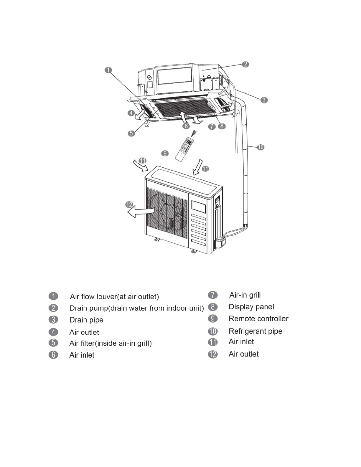
2.2 Part names of Indoor/Outdoor units
Ceiling Cassette Unit
5
Page 9
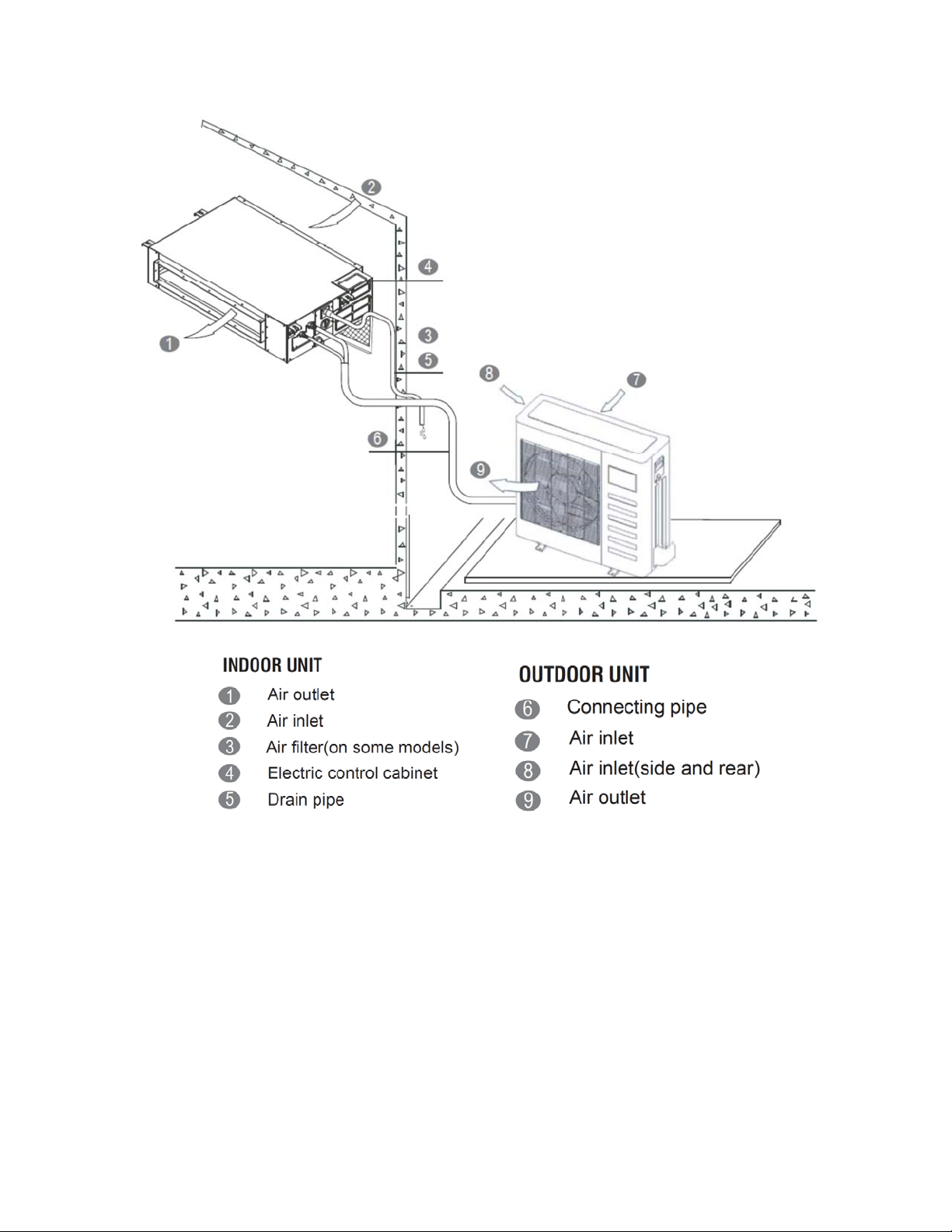
Ducted Concealed Units
6
Page 10
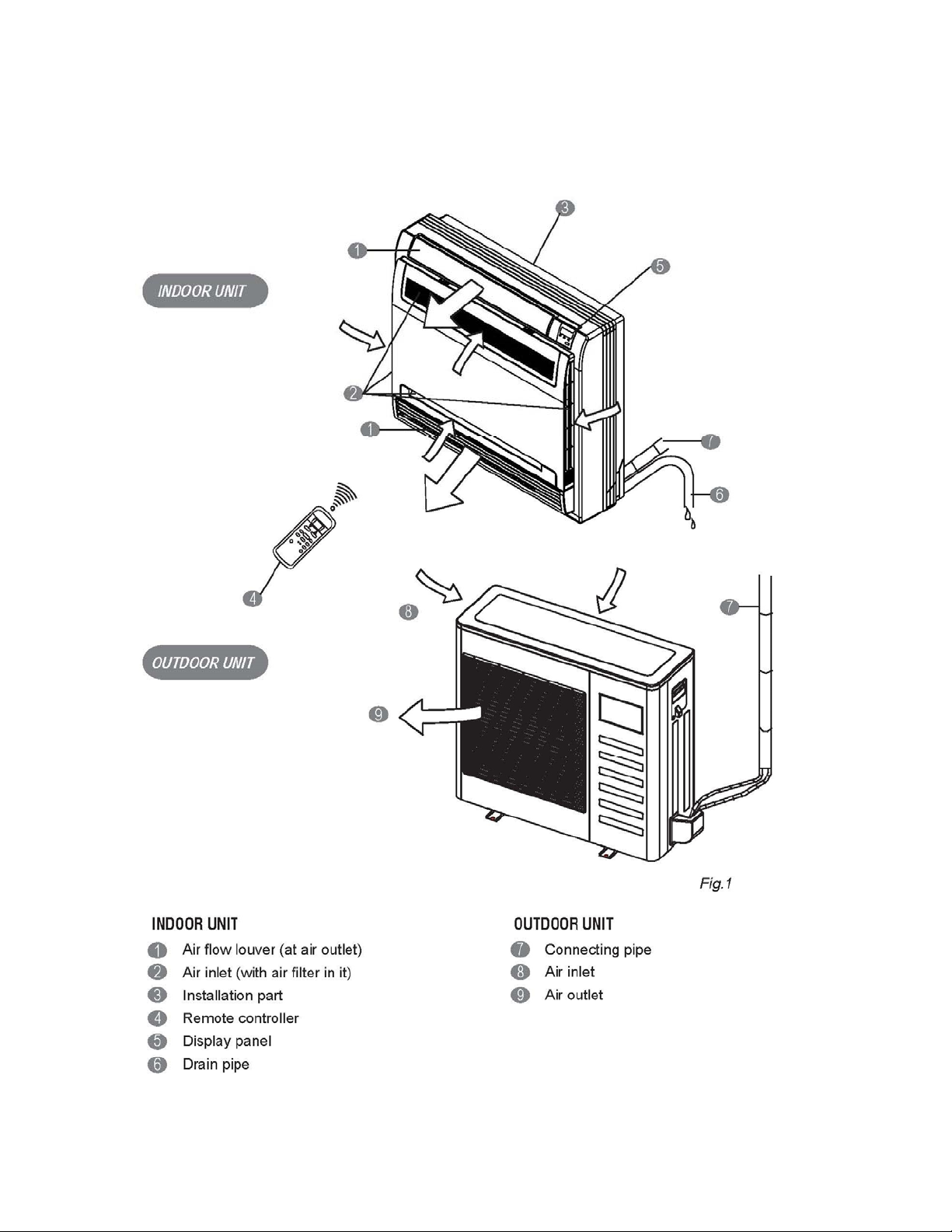
Floor Console Units
7
Page 11
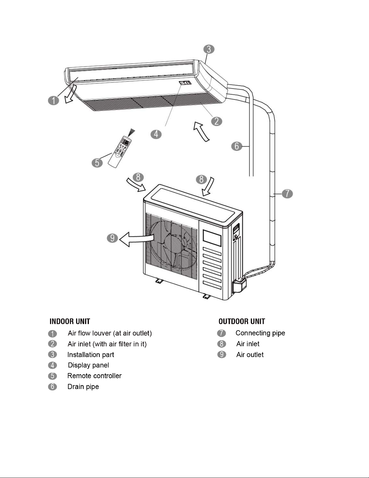
Ceiling-Floor Units
8
Page 12
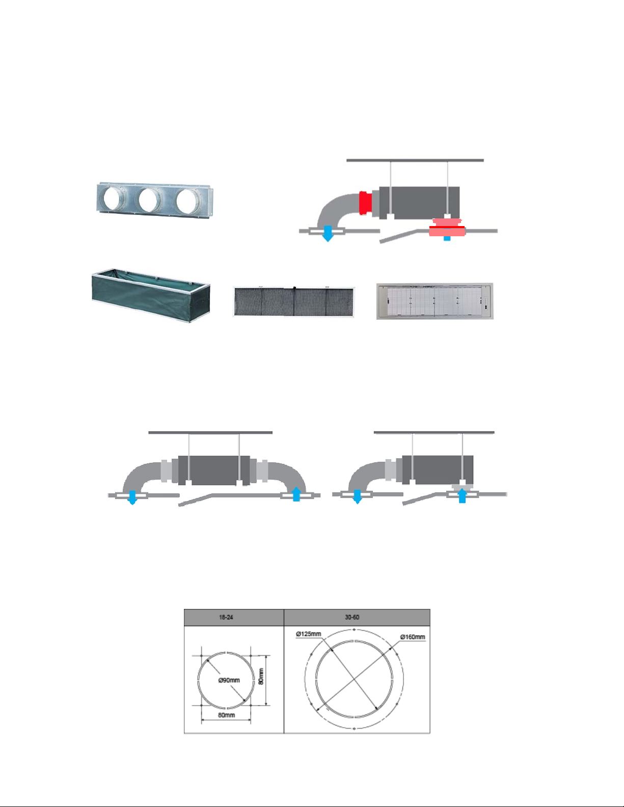
2.3 Features
2.3.1 Duct Units
2.3.1.1 Installation accessories: (Field Supplied / Optional)
Front Board, Canvas Air Passage, Filter, Panel, for easy installation
2.3.1.2 Easy Installation: Two air inlet styles (Bottom side or Rear side)
Air inlet from rear is standard for all capacity; air inlet from bottom is optional.
The size of air inlet frame from rear and bottom is same, it’s very easy to move the cover from
bottom to rear side, or from rear to the bottom, in order to matching the installation condition.
Panel
Air intake from rear (Standard)
2.3.1.3 Fresh air intake function
Install one duct from the reserved fresh-air intake to outdoor.
Continually inhale the fresh air to improve the quality of the indoor air, fulfills air quality more
healthy and comfortable.
9
Air intake from bottom (Optional)
Page 13
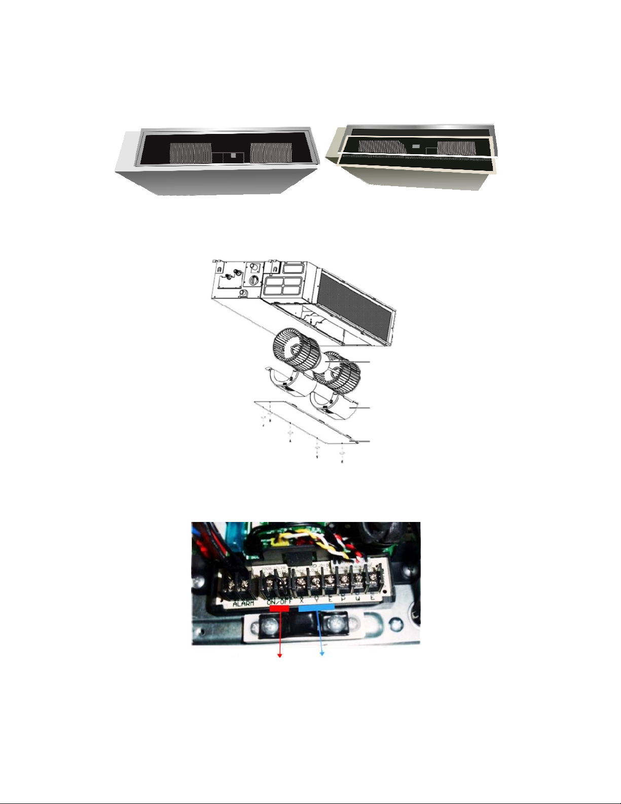
2.3.1.4 Easy maintenance
Clean the filter (Optional, standard product without filter)
It is easy to draw out the filter from the indoor unit for cleaning, even the filter is installed in rear
side or bottom side.
Replace the motor or centrifugal fan
Remove the ventilated panel firstly. Remove a half of blower housing and take out the motor with
centrifugal fan. Directly remove two bolts, and then replace the motor or centrifugal fan easily.
Motor
Blower Housing
Ventilated Panel
2.3.1.5 Reserved remote on-off and central control ports
Reserved remote on-off ports and central control ports, can connect the cable of an on-off
controller or a central controller to realize remote on-off control function or group control function.
Remote on-off ports Central control ports
2.3.1.6 Built-in drain pump (Optional):
Built-in drain pump can lift the water to 750mm upmost. It’s convenient to install drainage piping
under most space condition.
10
Page 14

2.3.2.7 Build-in Drain Pump with float switch
The drain pump can lift the condensing water up to 750mm upmost.
It’s convenient to install drainage piping under most space condition.
750mm upmost
2.3.1.8 Built-in display board
The standard indoor unit can be controlled by wired controller.
There is a display board with a receiver in the E-box. Move out the display, and fix it in other place,
even in the distance of 10m. The unit will realized remoter control.
The wired controller and the display board can display the error code or production code when the
chips detect some failure.
Wired Controller (Standard)
Remote Controller (Optional)
Display
11
Page 15
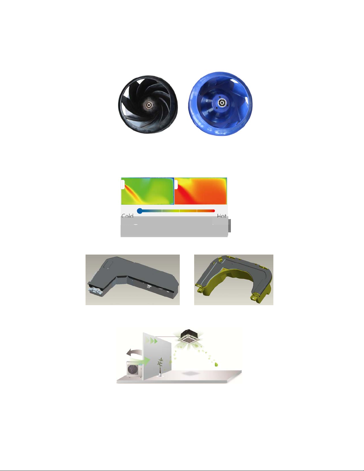
2.3.2 Cassette Unit
2.3.2.1 Lower Noise
Optimize air channel system design to ensure the maximum quietness and comfort.
Noise max down 6dB.
2.3.2.2 Turbo mode (Optional)
Turbo function can boost cooling or heating speed in a short period, and makes the room cool
down or heat up rapidly.
2.3.2.3 Fire-proof controller box
Electrical control box adopts new design, which can meet higher fire safety requirements.
Old
Common vs. Turbo
Cold
Turbo Mode (After 30 min)
New
Hot
New
2.3.2.4 Fresh Air
Fresh air intake function bring you fresh and comfortable air feeling.
2.3.2.5 Wired controller (Optional)
Compared with infrared remote controller, wired controller can be fixed on the wall and avoid
mislaying. It's mainly used for commercial zone and makes air conditioner control more
convenient.
12
Old
Page 16
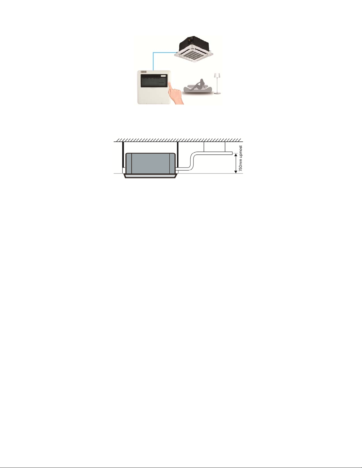
2.3.2.6 Build-in Drain Pump
The drain pump can lift the condensing water up to 750mm upmost.
It’s convenient to install drainage piping under most space condition.
2.3.2.7Terminals for alarm lamp and long-distance on-off controller connection are standard
Reserve terminals for the connection of alarm lamp and long-distance on-off controller, more
human control.
13
Page 17
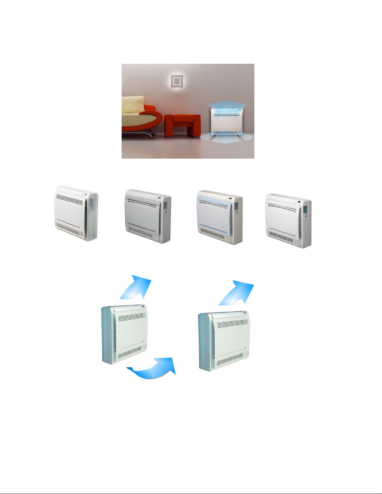
2.3.3 Console
2.3.3.1. Modern and elegant appearance
The simple and stylish designs can nicely harmonies with your living space.
3.2.3.2. Four panels optional
2.3.3.3. Two air-outlet ways
Cooling mode
Quick Cooling To maintain room temp
Air outlet from top and bottom to make quick cooling ------When the A/C is just switched on, or
room temp. is still high, cold air will be blown out from top and bottom air outlet to cool down the
room quickly
Air outlet from top to maintain room temp. ----When the room has been cooled down, or the A/C
has been opened over 1 hour, cold air only from the top outlet to keep constant room temp
14
Page 18
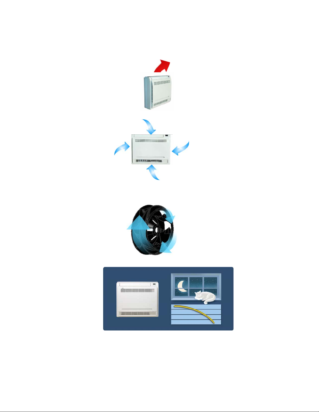
Heating mode
Anti-cold air ------When the AC is just turn on, temperature of evaporator is very low, in this case,
in order to prevent cold air direct blowing, only the upper louver is opened in a high position, the
lower louver closed.
2.3.3.4. Four air inlets
2.3.3.5. Low noise
DC indoor fan motor, which has five speeds.
Low noise and energy saving.
Advanced centrifugal fan technology makes a fast airflow and reduces the indoor noise.
2.3.3.6. Golden fin is optional.
2.3.3.7. Active carbon filter is standard
15
Page 19
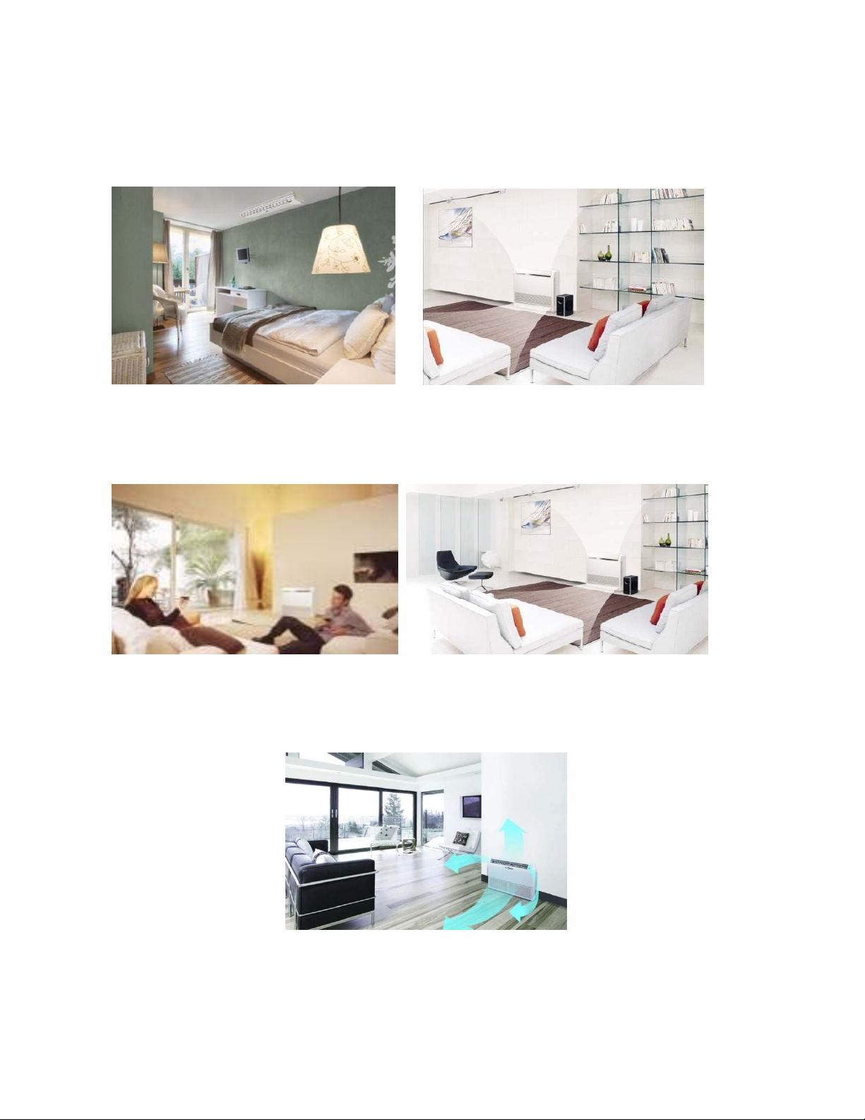
2.3.1 Ceiling-floor Units
2.3.1.1 Two-way installation
The rounded design of the ceiling and floor type air conditioner allows either ceiling or floor-level
installation. Ceiling installation saves room space, while floor installation helps prevent the loss of warm
air.
2.3.1.2 Brief design
Brief design that is suitable for any interior will not only give you cooling and heating performance but
also upgrade your lifestyle.
2.3.1.3 3D airflow
Vertical air flow and horizontal airflow can be adjusted by remote controller, the cooperation of the two airflow
ways help to spread air comfortably throughout even a large room. With these functions, the whole room can be
evenly air-conditioned for both floor-level and ceiling installation.
16
Page 20
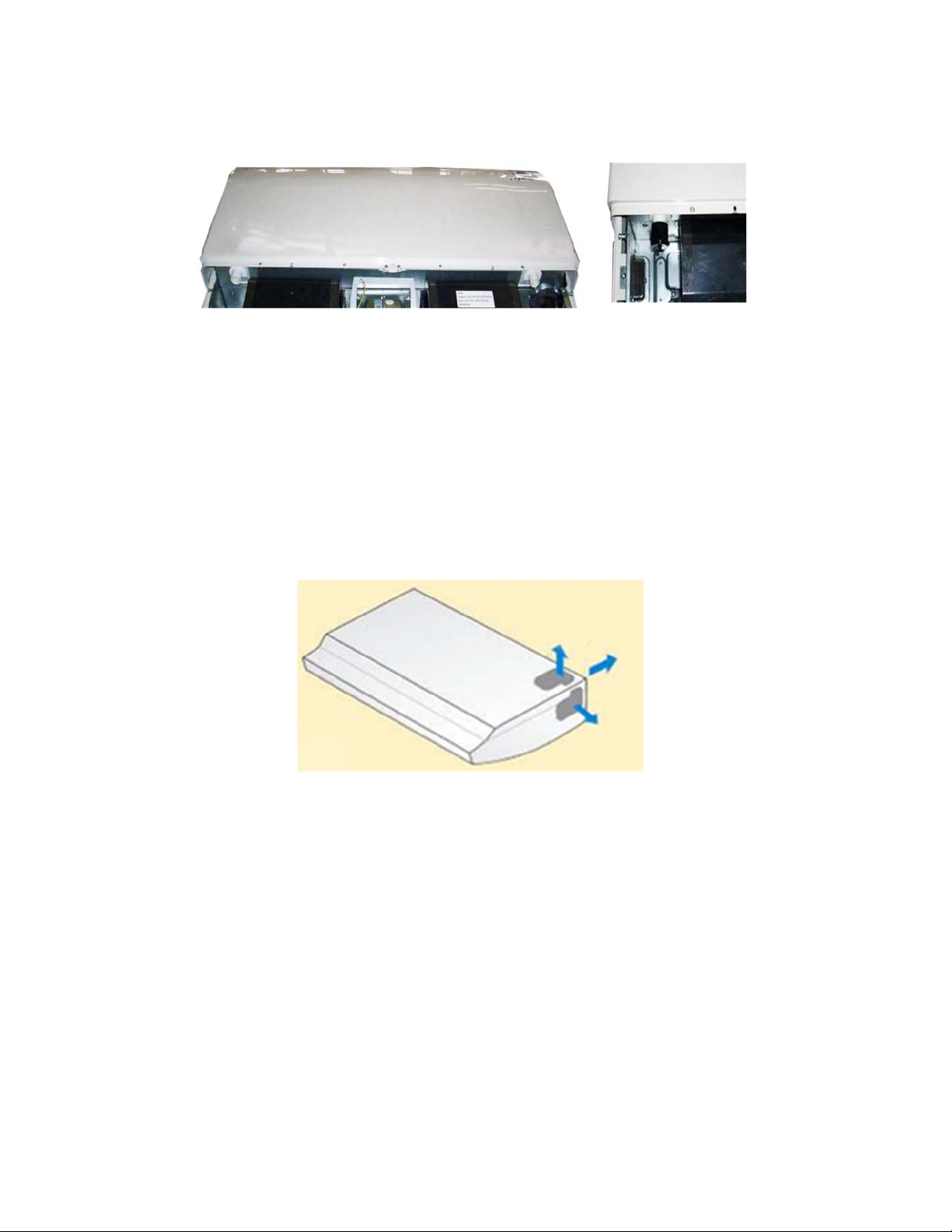
2.3.1.4 Optional drainage pipe connection
Both right side and left side drainage holes are available to avoid the space limitation for drainage pipe
installation. Make you more convenient during installation.
C Panel (LED display) D Panel
2.3.1.5 Convenience operating and easy maintenance
Remote controller as standard, wired controller for optional.
The filter without screw fixed, can be took out easily.
2.3.1.6 Easy installation, save working time
The pipes can be connected from bottom, back and right side, makes the installation more easily.
The wiring works can be finished before installation.
2.3.1.7 Outside water pump for optional when ceiling installation.
17
Page 21
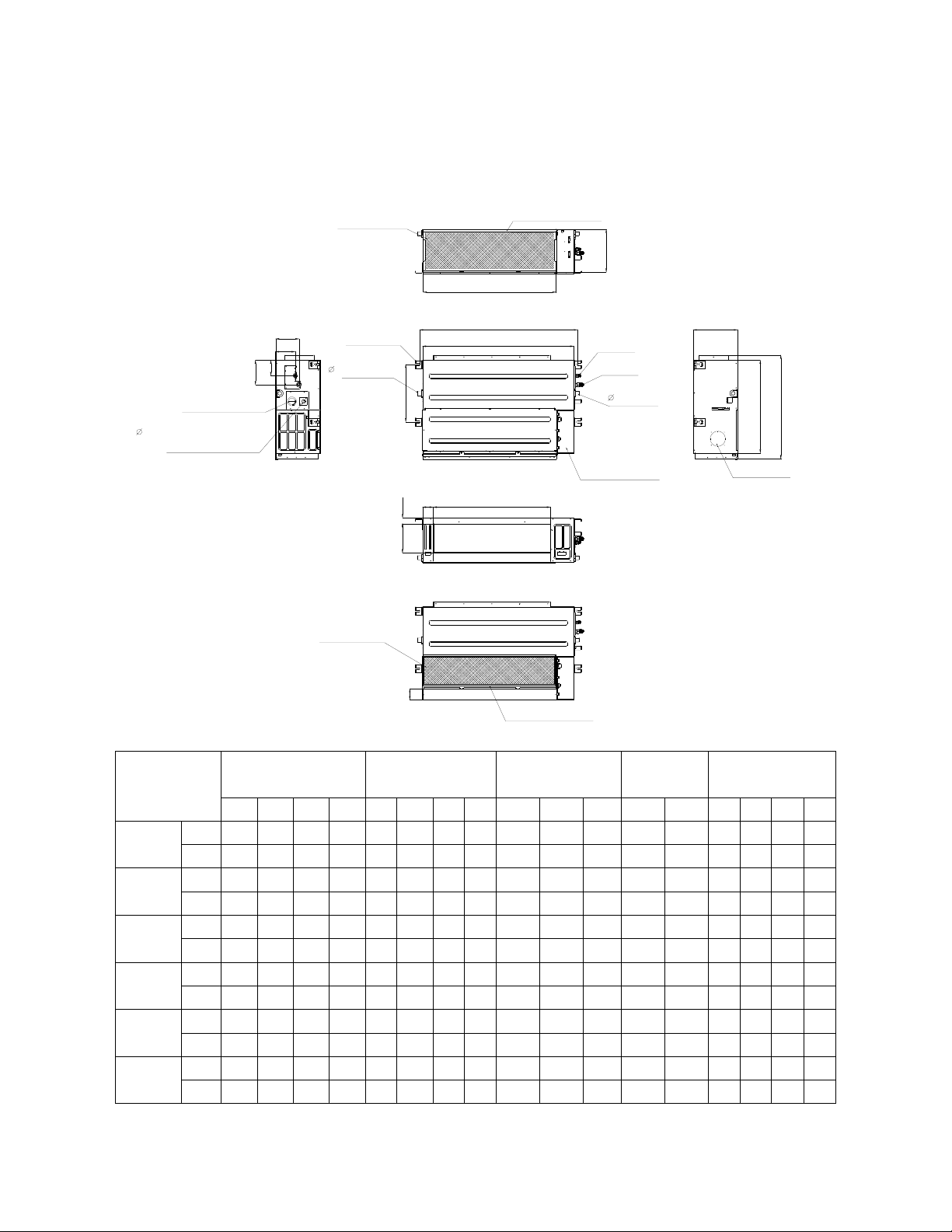
3. Dimension
3.1 Indoor Unit
Duct Units
Air filter ( optional )
air inlet from rear side
J
I
Test mouth & Test cover
25 Drain connecting pipe
( for pump )
Capacity (KBtu)
mm
9
12
18
24
36
48
in
mm
in
mm
in
mm
in
mm
in
mm
in
B
Fresh air intake
D
C
W2
H2
H1
W1
4-install hanger
25 Drain pipe
Air filter ( optional )
L
A
M
G
H
K
FE
air inlet from bottom side
Liquid side
Gas side
25 Drain pipe
Electric control box
Outline dimension(mm) Air outlet opening size Air return opening size
A B C D E F G H I J K L M H1 H2 W1 W2
700 210 635 570 65 493 35 119 595 200 80 740 350 120 143 95 150
27.56 8.27 25 22.44 2.56 19.41 1.38 4.69 23.43 7.87 3.15 29.13 13.78 4.72 5.63 3.74 5.91
700 210 635 570 65 493 35 119 595 200 80 740 350 120 143 95 150
27.56 8.27 25 22.44 2.56 19.41 1.38 4.69 23.43 7.87 3.15 29.13 13.78 4.72 5.63 3.74 5.91
920 210 635 570 65 713 35 119 815 200 80 960 350 120 143 95 150
36.22 8.27 25.00 22.44 2.56 28.07 1.38 4.69 32.09 7.87 3.15 37.80 13.78 4.72 5.63 3.74 5.91
920 270 635 570 65 713 35 179 815 260 20 960 350 120 143 95 150
36.22 10.63 25.00 22.44 2.56 28.07 1.38 7.05 32.09 10.24 0.78 37.80 13.78 4.72 5.63 3.74 5.91
1140 270 775 710 65 933 35 179 1035 260 20 1180 490 120 143 95 150
44.88 10.63 30.51 27.95 2.56 36.73 1.38 7.05 40.75 10.24 0.78 46.46 19.29 4.72 5.63 3.74 5.91
1200 300 865 800 80 968 40 204 1094 288 45 1240 500 175 198 155 210
47.24 11.81 34.06 31.50 3.15 38.11 1.57 8.03 43.07 11.34 1.77 48.82 19.69 6.89 7.80 6.10 8.27
Size of install
hanger
Size of refrigerant pipe
18
Page 22
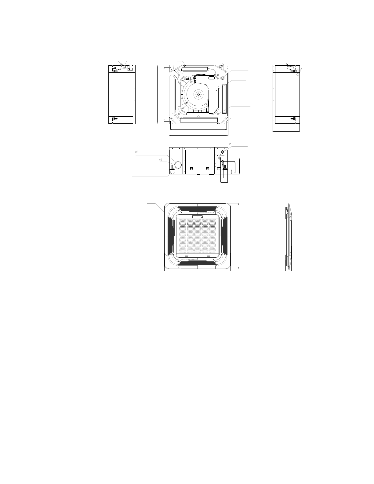
Cassette Units (9K, 12K, 18K)
Liquid side
Gas side
Fresh air intake
65
Wiring connection port
Panel
570
Body
523
545
570
75
( for Service )
E-parts box
4-Screw hole
(for install panel)
4-install hanger
32
44
42
68
Drain hole
Drain pipe
157
126
Wiring connection port
260
647
19
Page 23
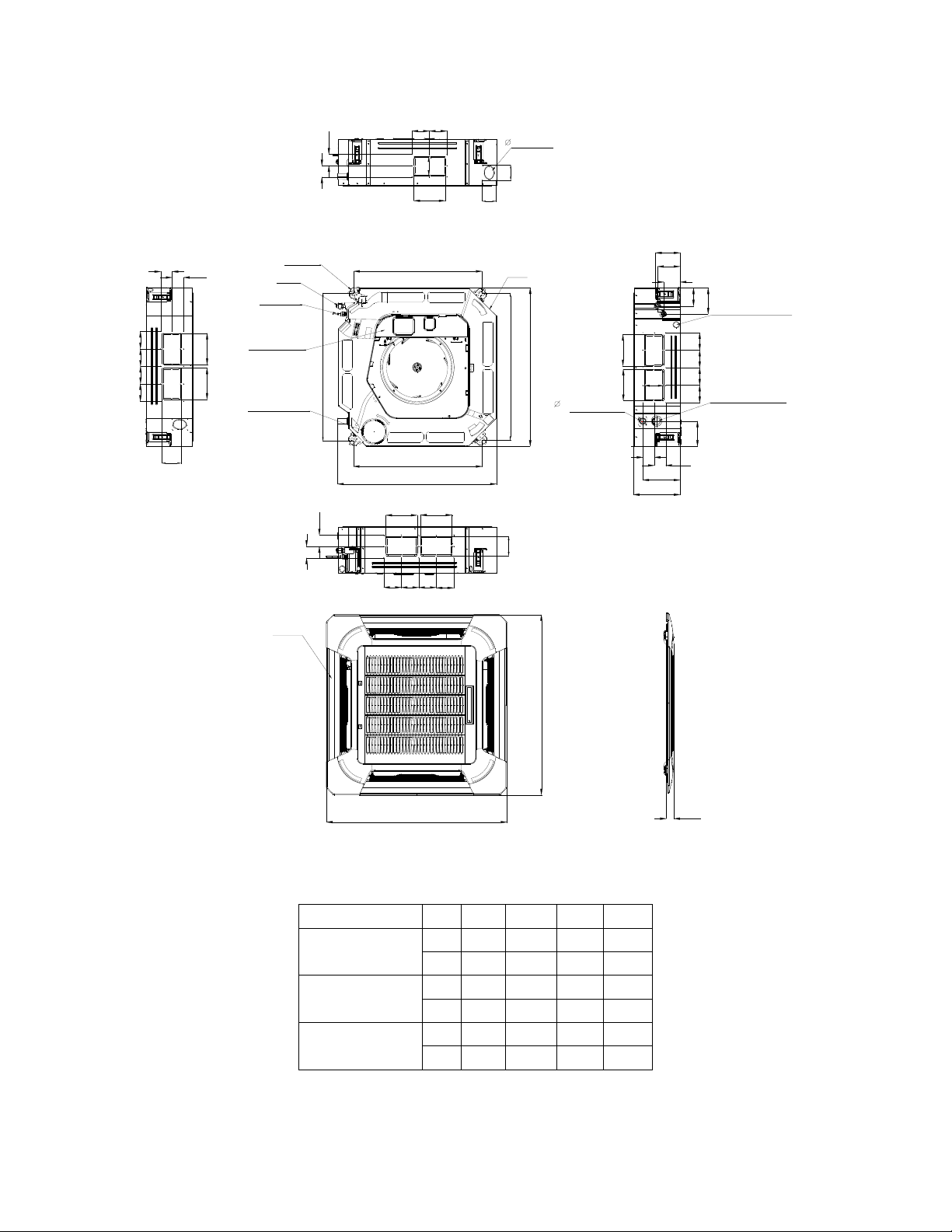
Cassette Units (24K, 36K, 48K)
D
D
D
D
92
9292
92
A
A
B
4-install hanger
Gas side
Liquid side
E-parts box
Service hole for
draining pump
780
D
D
92 92
75
Fresh air intake
B
A
680
680
840
A
A
80
80
136
Body
780
B
840
32
Drain hole
126
91
90
Wiring connection port
135
B
196
C
92929292
132
D
Test mouth &
Test cover
A
A
D
92 92
92
92
Panel
950
950
55
Capacity (Btu/h)
24K
36K
48K
A B C D
mm 160 75 205 50
inch 6.30 2.95 8.07 1.97
mm 160 95 245 60
inch 6.30 3.74 9.65 2.36
mm 160 95 287 60
inch 6.30 3.74 11.30 2.36
20
Page 24
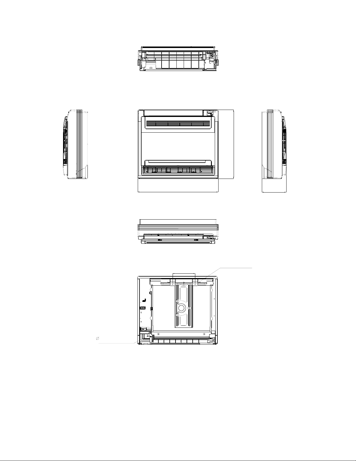
Console Units
600
16 Drain pipe
700
210
Hanging arm
195
Unit: mm
21
Page 25

Ceiling-floor Units (18K-48K)
2
-
0
4
Drain discharge port
120
Fresh air intake
94
Wiring connection port
2
-
3
3
120
A
204
140
Refrigerant pipe hole
B
C
D
Hanging arm
220
222
Capacity (Btu/h)
18K / 24K
36K
48K
A B C D
mm 1068 675 235 983
inch 42.05 26.57 9.25 38.70
mm 1285 675 235 1200
inch 50.59 26.57 9.25 47.24
mm 1650 675 235 1565
inch 64.96 26.57 9.25 61.61
22
Page 26
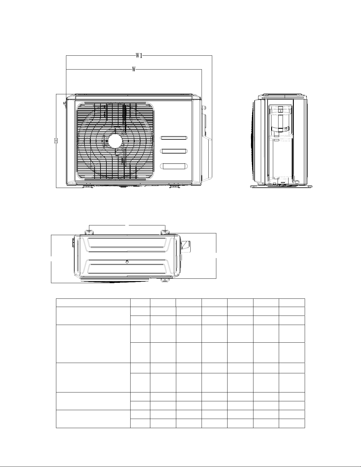
3.2 Outdoor Unit
A
D
Note: The above drawing is only for reference. The appearance of your units may be different.
Model W D H W1 A B
YN009GMFI22RPD
YN012GMFI22RPD
YN018GMFI22RPD
YN024GMFI22RPD
YN036GMFI17RUD
YN048GMFI17RUD
mm
inch
mm
inch
mm
inch
mm
inch
mm
inch
770 300 555 840 487 298
30.3 11.8 21.9 33.1 19.2 11.7
800 333 554 870 514 340
31.5 13.1 21.8 34.3 20.2 13.4
845 363 702 914 540 350
33.3 14.3 27.6 36.0 21.3 13.8
946 410 810 1030 673 403
37.2 16.1 31.9 40.6 26.5 15.9
952 415 1333 1045 634 404
37.5 16.3 52.5 41.1 25.0 15.9
B
23
Page 27

4. Service Space
4.1 Indoor Unit
Duct Units
Ensure enough space required for installation and maintenance.
200mm(7.87in) or more
All the indoor units reserve the hole to connect the fresh air pipe. The hole size as following
300mm(11.81in) or more
600mmx600mm/23.62inx23.62in
Check orifice
Cassette Units
Unit: mm
24
Page 28
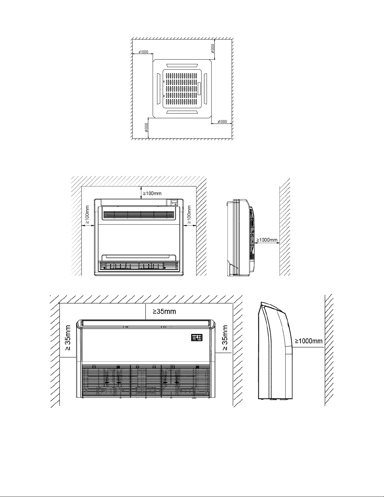
Console Unit
Ceiling-floor Units
25
Page 29
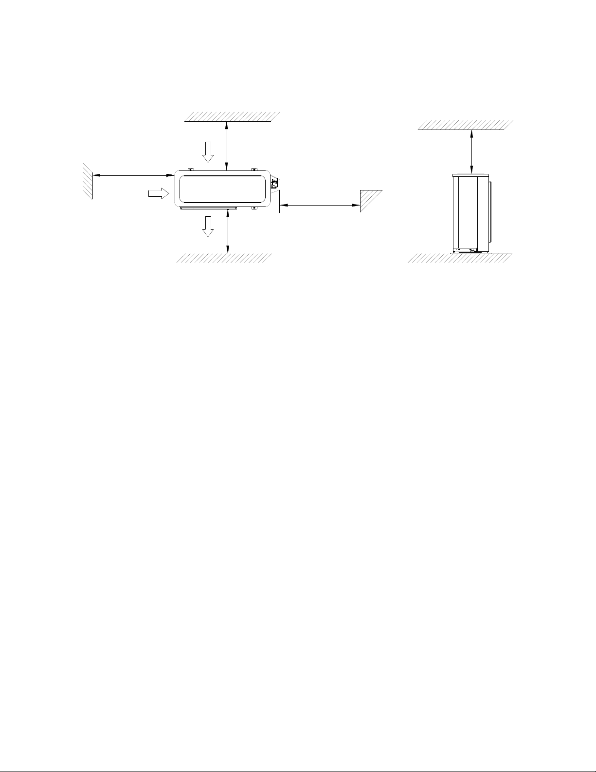
4.2 Outdoor Unit
(Wall or obstacle)
Air inlet
More than 30cm
(11.81in)
Air inlet
Air outlet
More than 30cm(11.81in)
Maintain channel
More than 60cm
(23.62in)
More than 200cm(78.74in)
More than 60cm
(23.62in)
26
Page 30
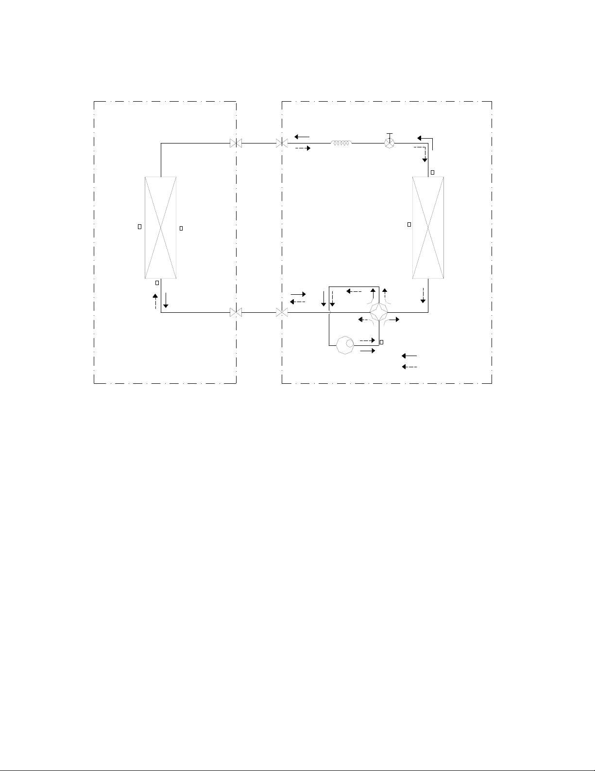
5. Refrigerant Cycle Diagram
INDOOR OUTDOOR
HEAT
EXCHANGE
(EVAPORATOR)
T2 Evaporator
temp. sensor
middle
T2B Evaporator
temp. sensor
outlet
T1 Room temp.
sensor
LIQUID SIDE
2-WAY VALVE
GAS SIDE
3-WAY VALVE
CAPILIARY TUBE
Compressor
Electronic
expansion valve
T4 Ambient
temp. sensor
4-WAY VALVE
T5 Discharge
temp. sensor
T3 Condenser
temp. sensor
COOLING
HEATING
HEAT
EXCHANGE
(CONDENSER)
27
Page 31
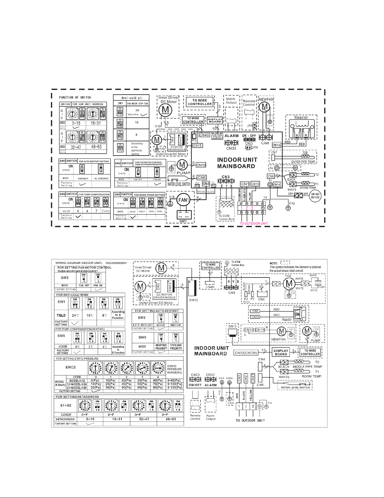
6. Wiring Diagram
6.1 Indoor Unit
CB009GMFILCFHD, CB012GMFILCFHD, CB018GMFILCFHD,CB024GMFILCFHD
RB009GMFILCFHD, RB012GMFILCFHD, RB018GMFILCFHD,RB024GMFILCFHD
28
Page 32
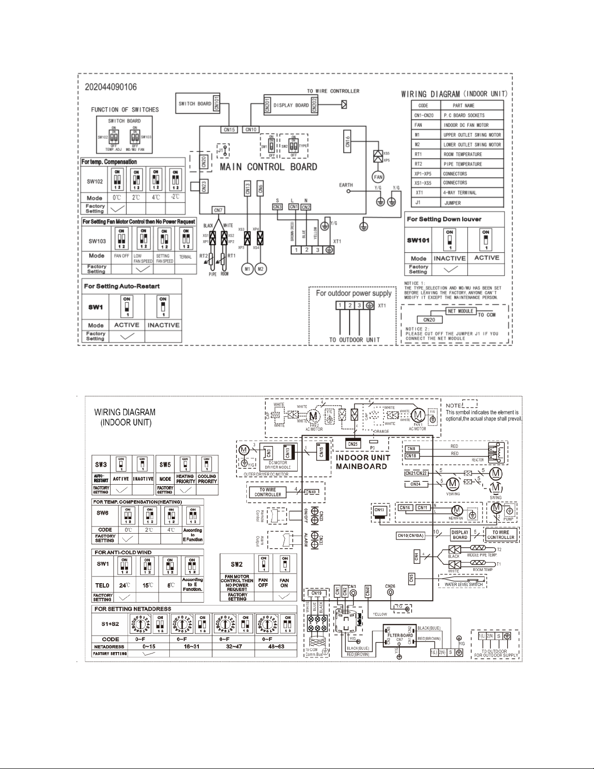
FB009GMFILCFHD, FB012GMFILCFHD
UB018GMFILCFHD
29
Page 33
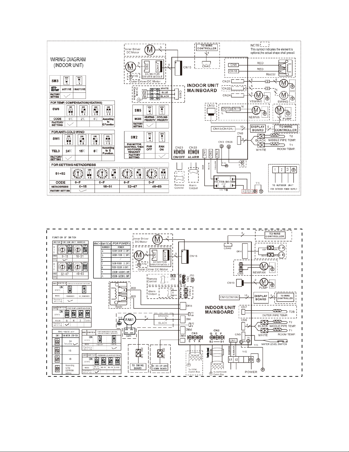
UB018GMFILCFHD
CB036GMFILCFHD,CB048GMFILCFHD
30
Page 34
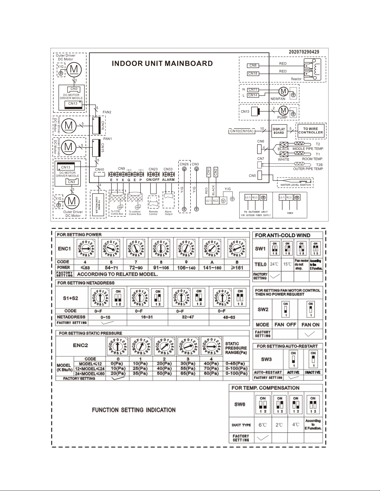
RB036GMFILCFHD,RB048GMFILCFHD
31
Page 35
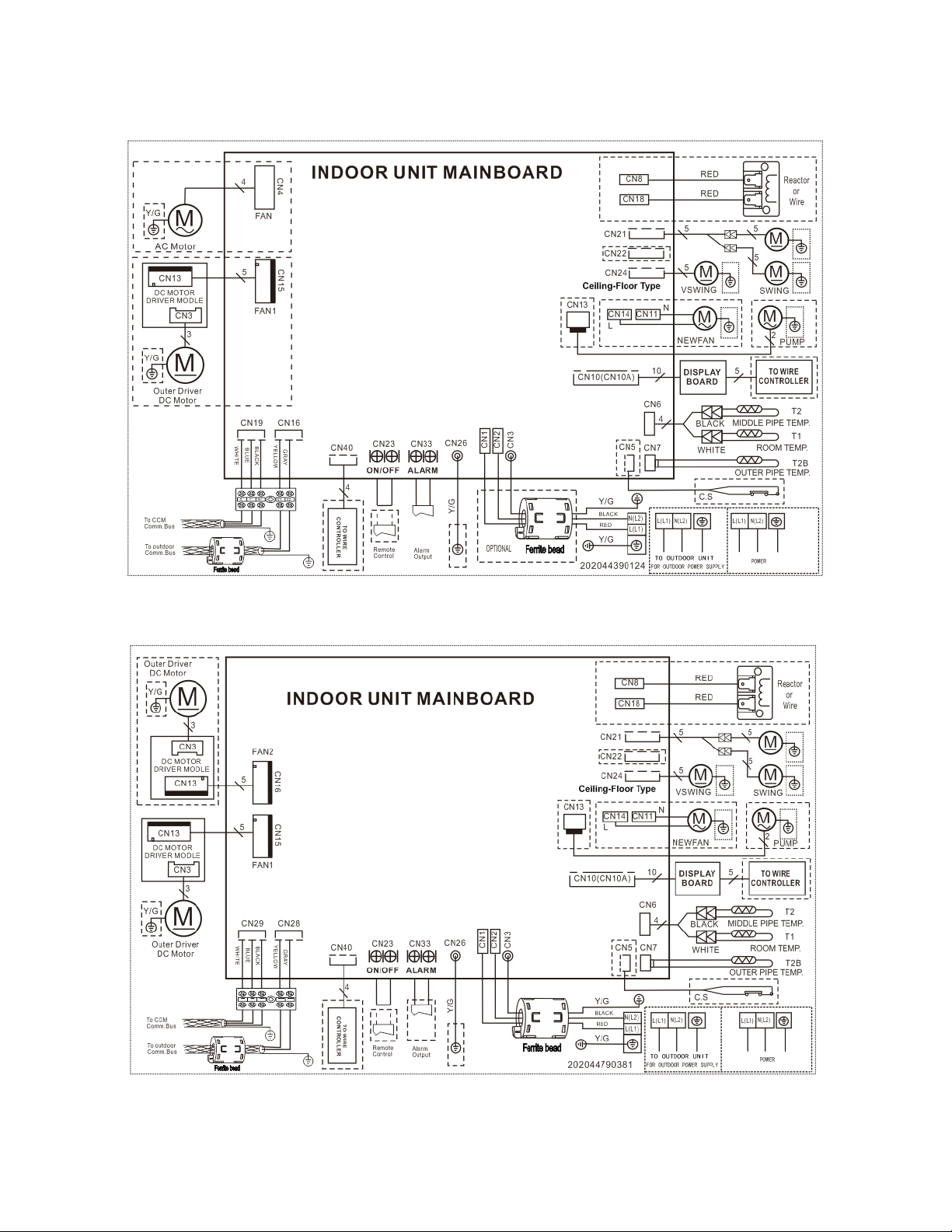
UB036GMFILCFHD
UB048GMFILCFHD
32
Page 36
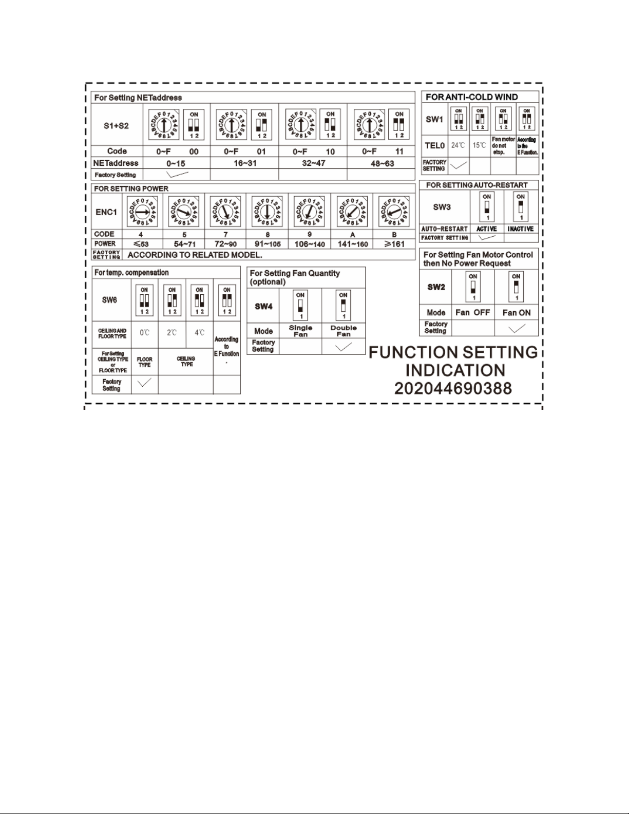
UB036GMFILCFHD, UB048GMFILCFHD
33
Page 37
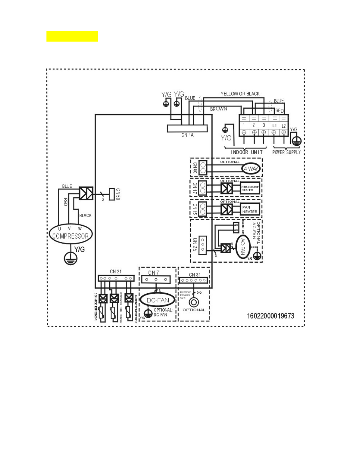
6.2 Outdoor Unit
YN009GMFI22RPD, YN012GMFI22RPD
34
Page 38
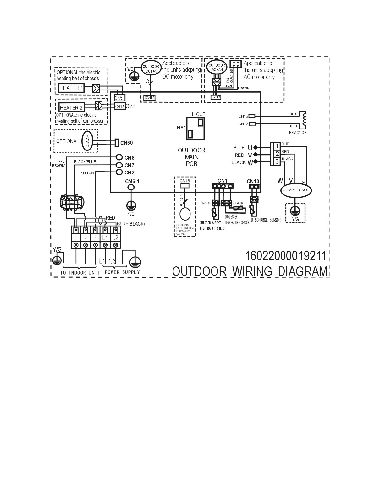
YN018GMFI22RPD
35
Page 39
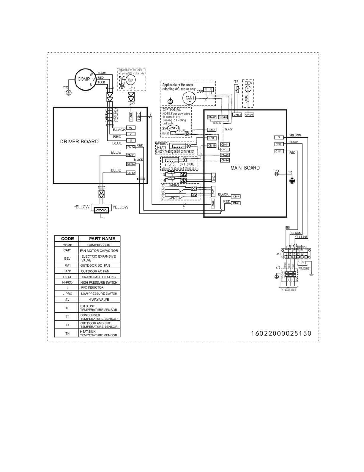
YN024GMFI22RPD
36
Page 40
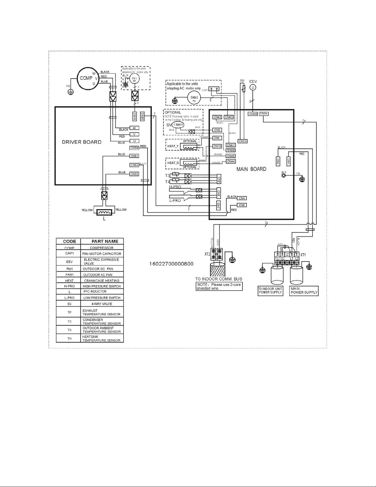
YN036GMFI17RUD
37
Page 41
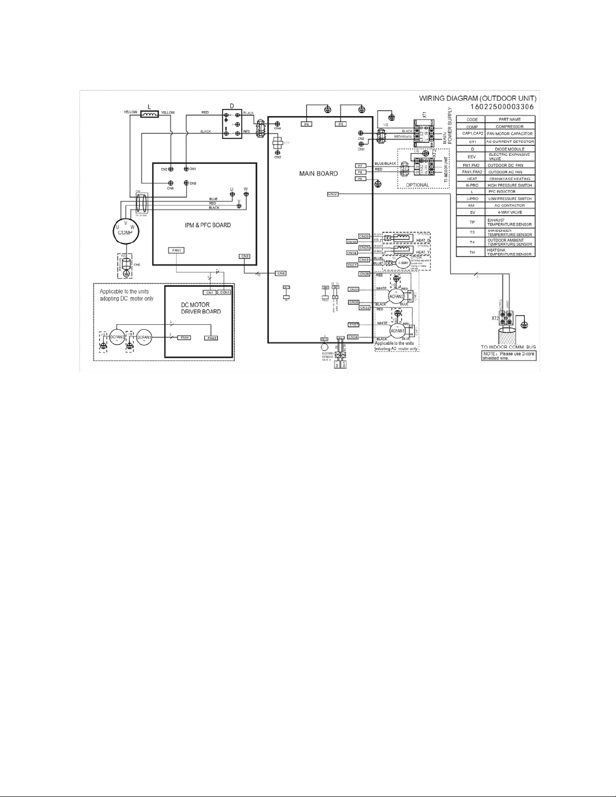
YN048GMFI17RUD
38
Page 42
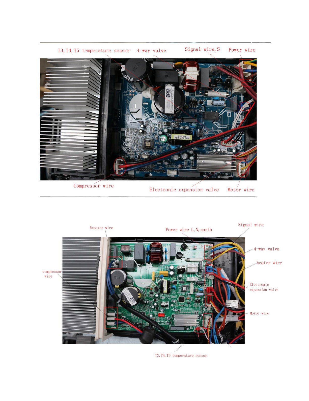
Outdoor Controller Set of
For YN009GMFI22RPD, YN012GMFI22RPD:
For YN018GMFI22RPD:
39
Page 43
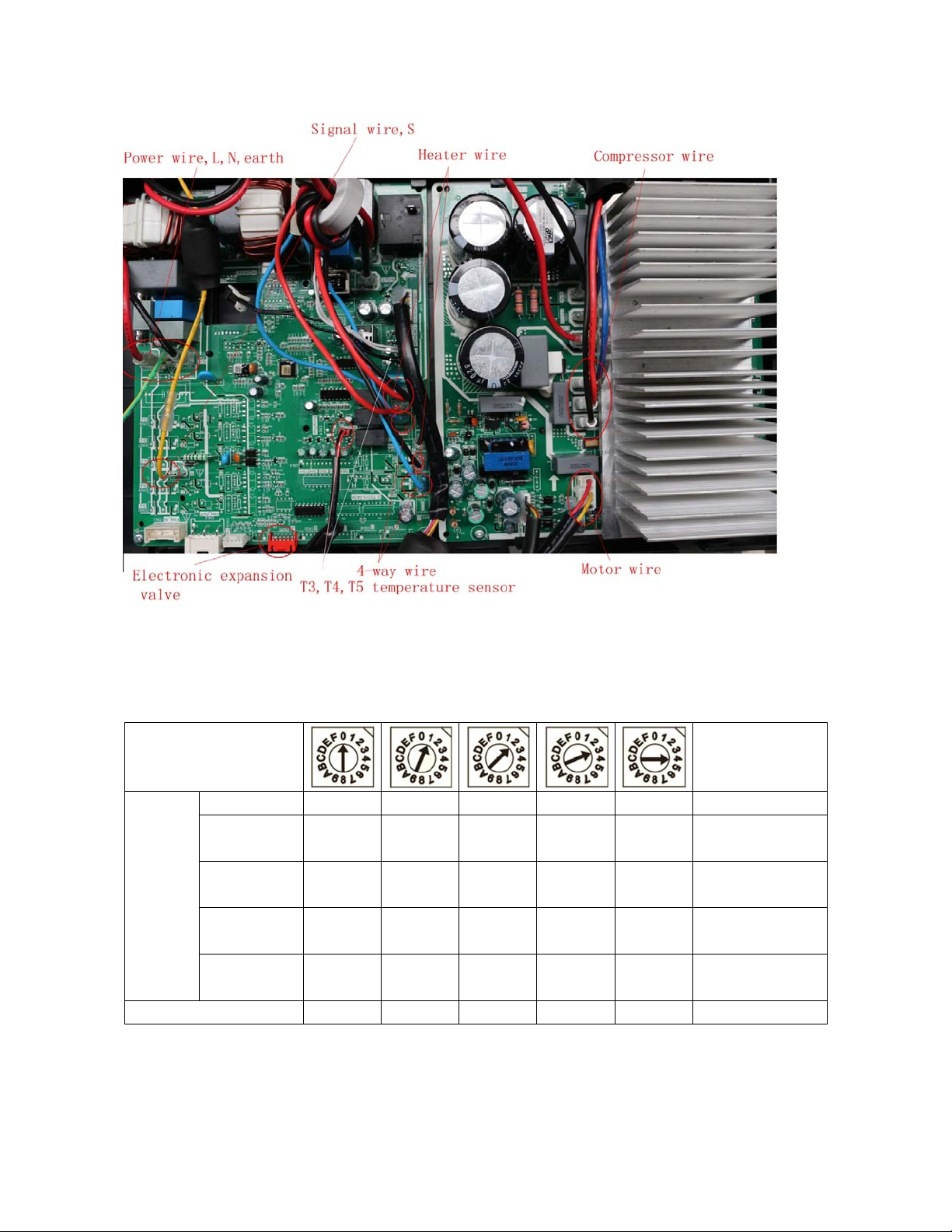
For YN024GMFI22RPD, YN036GMFI17RUD
7. Fan Curves
ENC2
Model 0 1 2 3 4
Model≤12
Model
(K Btu/h)
Factory Setting
Model=18
18<Model≤24
24<Model≤60
0.02
(5)
0.04
(10)
0.04
(10)
0.08
(20)
√
0.04
(10)
0.10
(25)
0.10
(25)
0.14
(35)
0.08
(20)
0.14
(35)
0.16
(40)
0.20
(50)
0.12
(30)
0.18
(45)
0.22
(55)
0.26
(65)
0.16
(40)
0.22
(55)
0.28
(70)
0.32
(80)
Static Pressure
Range In. WG (Pa)
0-0.18
(0-45)
0-0.28
(0-70)
0-0.40
(0-100)
0-0.40
(0-100)
40
Page 44
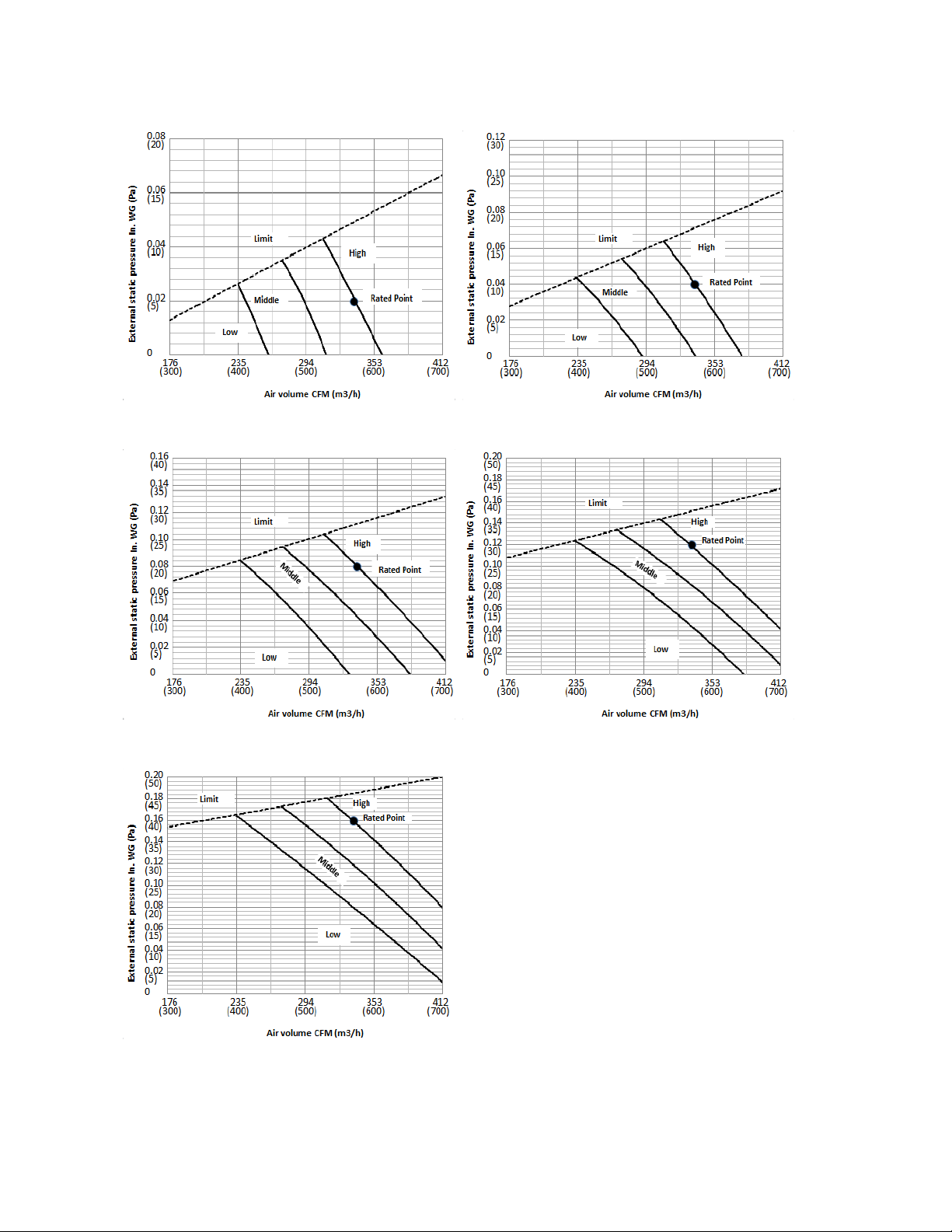
RB009GMFILCFHD
Code 0 Code 1
Code 2 Code 3
Code 4
41
Page 45
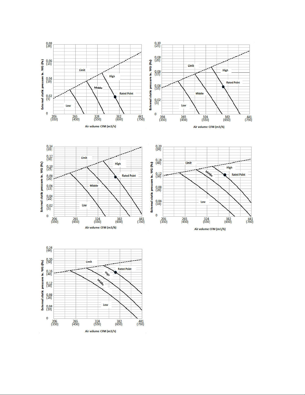
RB012GMFILCFHD
Code 0 Code 1
Code 2 Code 3
Code 4
42
Page 46
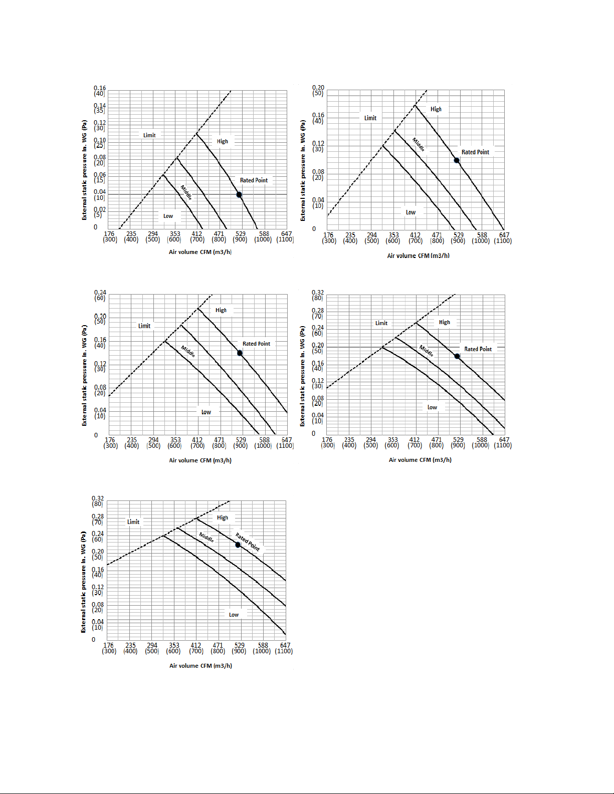
RB018GMFILCFHD
Code 0 Code 1
Code 2 Code 3
Code 4
43
Page 47
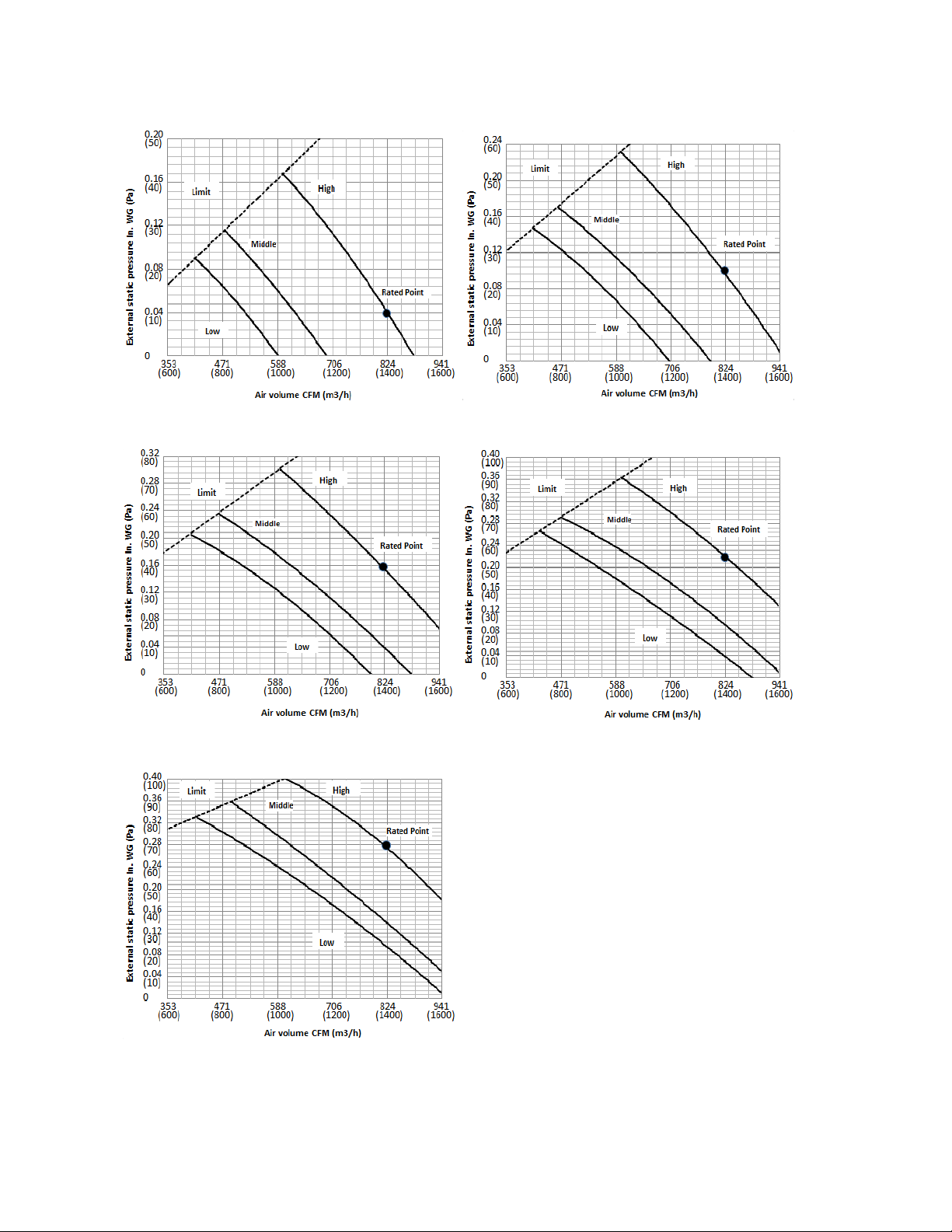
RB024GMFILCFHD
Code 0 Code 1
Code 2 Code 3
Code 4
44
Page 48

RB036GMFILCFHD
Code 0 Code 1
Code 2 Code 3
Code 4
45
Page 49
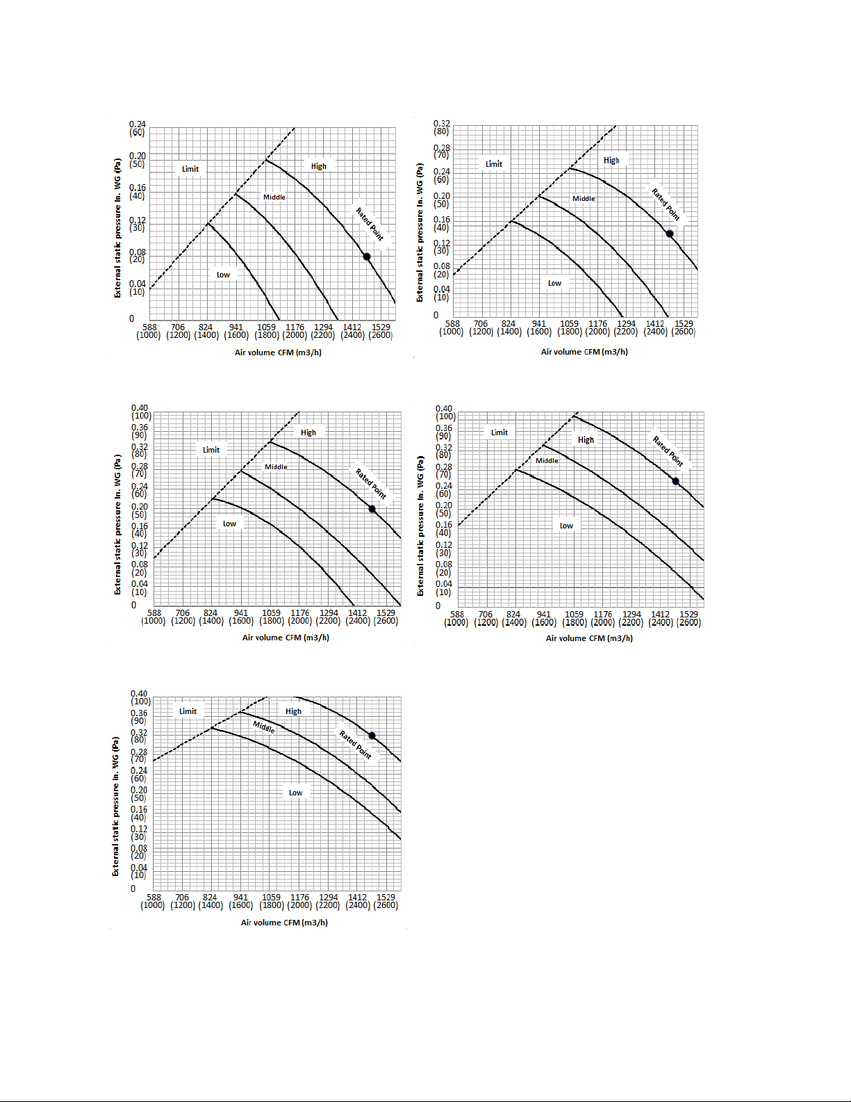
RB048GMFILCFHD
Code 0 Code 1
Code 2 Code 3
Code 4
46
Page 50
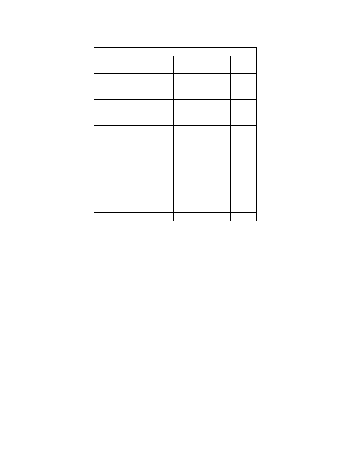
8 Electric Characteristics
Model
CB009GMFILCFHD
RB009GMFILCFHD
FB009GMFILCFHD
CB012GMFILCFHD
RB012GMFILCFHD
FB012GMFILCFHD
CB018GMFILCFHD
RB018GMFILCFHD
UB018GMFILCFHD
CB024GMFILCFHD
RB024GMFILCFHD
UB024GMFILCFHD
CB036GMFILCFHD
RB036GMFILCFHD
UB036GMFILCFHD
CB048GMFILCFHD
RB048GMFILCFHD
UB048GMFILCFHD
Indoor Unit
Hz Voltage Min. Max.
60 208-230V 187V 253V
60 208-230V 187V 253V
60 208-230V 187V 253V
60 208-230V 187V 253V
60 208-230V 187V 253V
60 208-230V 187V 253V
60 208-230V 187V 253V
60 208-230V 187V 253V
60 208-230V 187V 253V
60 208-230V 187V 253V
60 208-230V 187V 253V
60 208-230V 187V 253V
60 208-230V 187V 253V
60 208-230V 187V 253V
60 208-230V 187V 253V
60 208-230V 187V 253V
60 208-230V 187V 253V
60 208-230V 187V 253V
47
Page 51
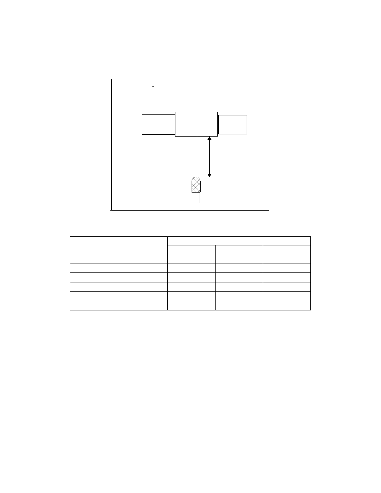
9 Sound Level
9.1 Indoor unit
Concealed Duct Type
Discharge
Suction
DuctDuct
1.4m
Microphone
Model
RB009GMFILCFHD 37 34 31
RB012GMFILCFHD
RB018GMFILCFHD 35 33 31
RB024GMFILCFHD 50 47 45
RB036GMFILCFHD
RB048GMFILCFHD 44 47 41
H M L
39 36 32
53 49 45
Noise level dB(A)
48
Page 52
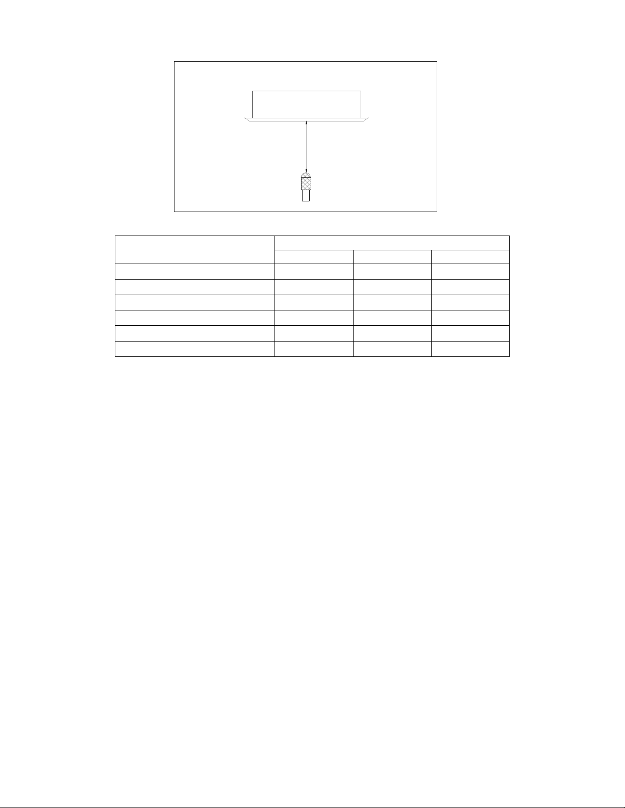
1.4m
Microphone
Model
CB009GMFILCFHD 41 39 37
CB012GMFILCFHD 41 38 35
CB018GMFILCFHD
CB024GMFILCFHD 51 47 43
CB036GMFILCFHD 52 47 44
CB048GMFILCFHD
H M L
46 43 41
53 49 45
Noise level dB(A)
49
Page 53
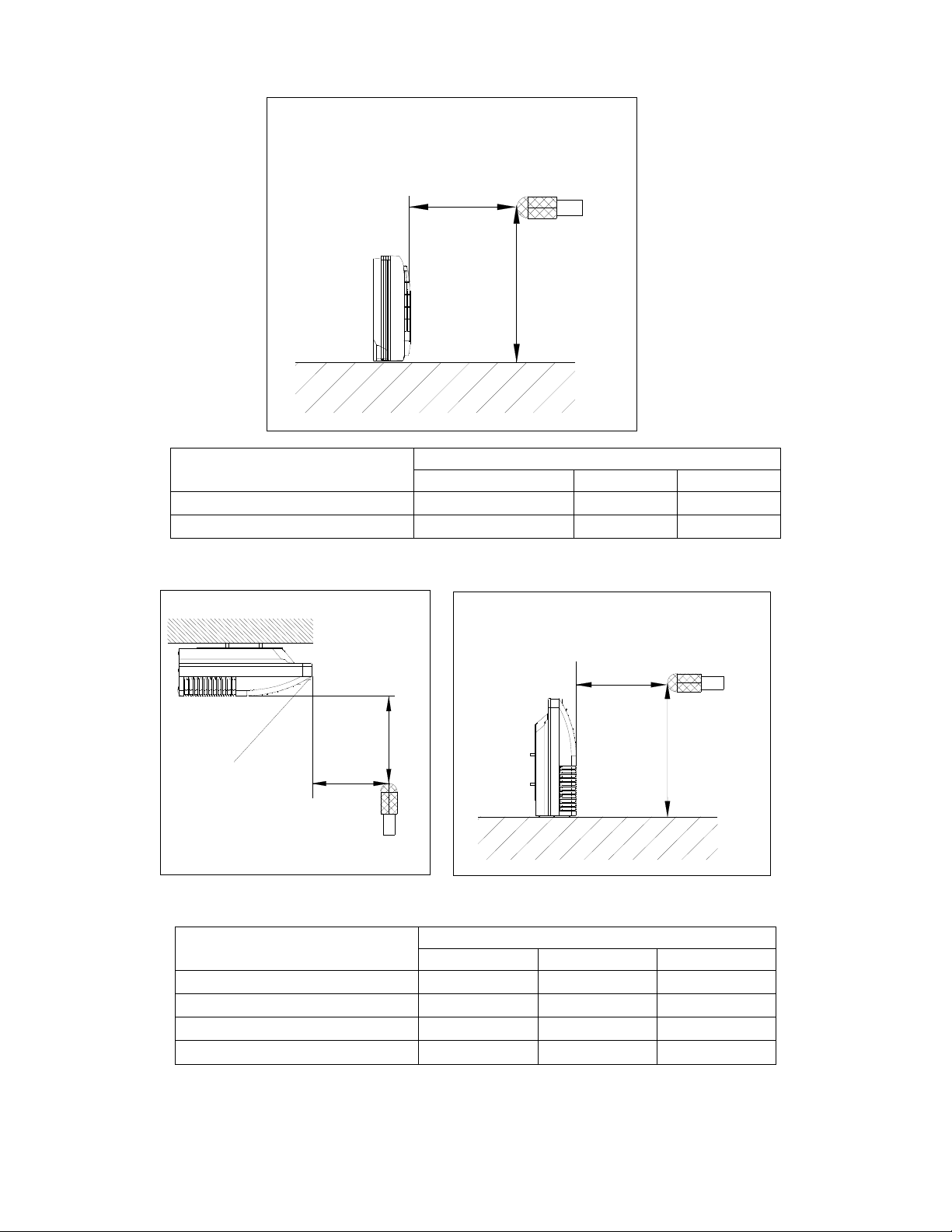
Microphone
1m
1.5m
Model
FB009GMFILCFHD 45 41 35
FB012GMFILCFHD
H M L
44 42 38
Noise level dB(A)
Microphone
1m
Air outlet side
1m
1m
Microphone
1.5m
Model
UB018GMFILCFHD 47 44 38
UB024GMFILCFHD
UB036GMFILCFHD 55 48 41
UB048GMFILCFHD 57 54 52
H M L
53 49 45
Noise level dB(A)
50
Page 54
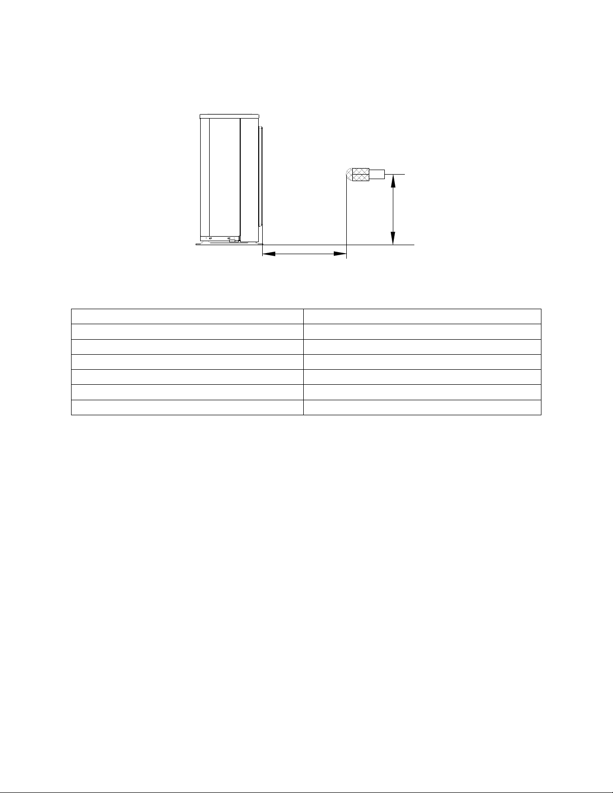
9.2 Outdoor unit
Outdoor Unit
Microphone
H
1.0m
Note: H= 0.5 × height of outdoor unit
Model Noise Level dB(A)
YN009GMFI22RPD
YN012GMFI22RPD
YN018GMFI22RPD
YN024GMFI22RPD
YN036GMFI17RUD
YN048GMFI17RUD
56
57
59
61
65
63
51
Page 55
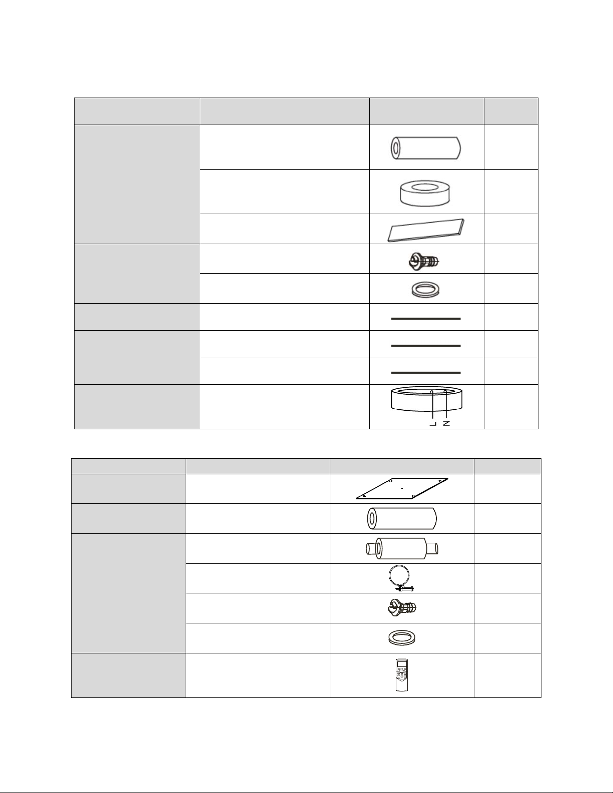
10 Accessories
Duct Units
Name Shape Quantity
Tubing & Fittings
Drainpipe Fittings
(for cooling & heating)
Wired controller & Its Frame
Others
EMS & It’s fitting
Soundproof / insulation sheath
Binding tape
Seal sponge
Drain joint
Seal ring
Wired controller
,
s manual
Owner
Installation manual
Magnetic ring (twist the electric wires L
and N around it to five circles)
2
1
1
1
1
1
1
1
1
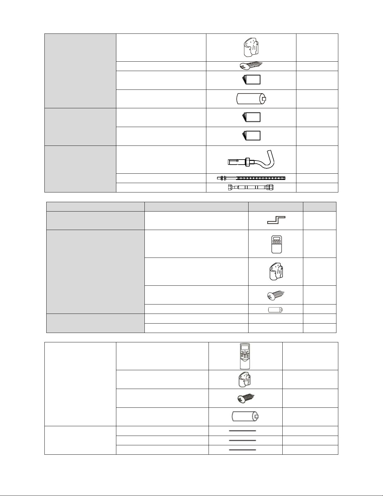
Cassette Units
Name Shape Quantity
Installation Fittings
Tubing & Fittings
Drainpipe Fittings
Remote controller & Its
Frame(The product you
have might not be
Installation paper board
Soundproof / insulation sheath
Out-let pipe sheath
Out-let pipe clasp
Drain joint
Seal ring
Remote controller & Its Frame
52
1
1
1
1
1
1
1
Page 56
provided the following
accessories)
Remote controller holder
1
Mounting screw(ST2.9×10-C-H)
Remote controller manual
Alkaline dry batteries (AM4)
Owner's manual
Others
Installation manual
Installation accessory
(The product you have
might not be provided the
following accessories
Expansible hook
Installation hook
Orifice
Console Units
Name Shape Quantity
Installation fittings Hook
Remote controller
2
1
2
1
1
4
4
1
2
1
Remote controller & Its Frame
Others
Ceiling-floor Units
1. Remote controller
Remote controller & Its
holder
Others
2. Remote controller holder
3. Mounting screw (ST2.9×10-C-H)
4. Alkaline dry batteries (AM4)
5. Owner's manual
6. Installation manual
7. Remote controller manual
Frame
Mounting screw(ST2.9×10-C-H)
Alkaline dry batteries (AM4)
Installation manual / 1
Owner's manual / 1
1
2
2
1
1
2
2
1
1
1
53
Page 57
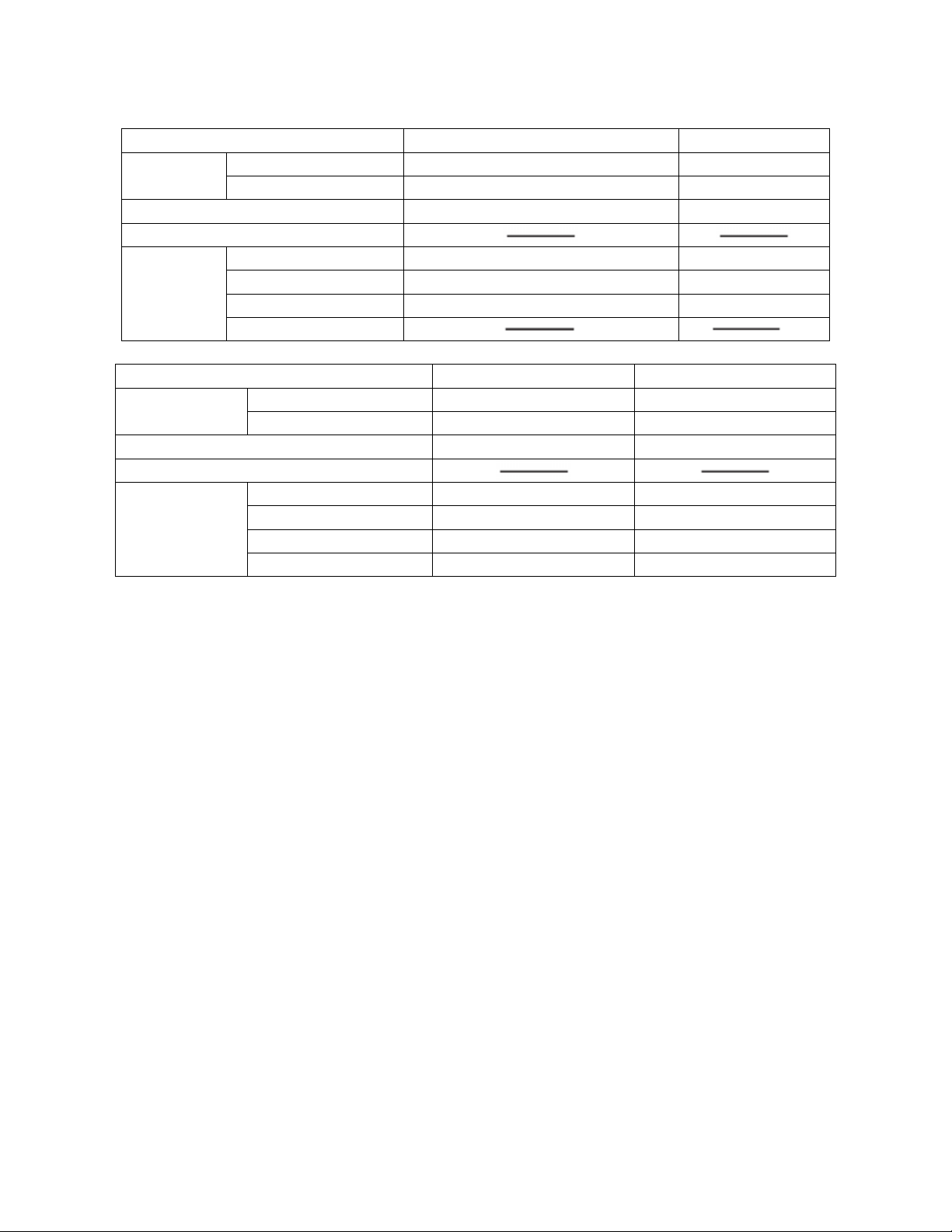
11 The Specification of Power
9K-18K
Type
Power
Circuit Breaker/ Fuse (A) 25/20 40/30
Indoor Unit Power Wiring (mm2)
Indoor/Outdoor
Connecting
Wiring
Phase 1-phase 1-phase
Frequency and Voltage 208-230V, 60Hz 208-230V, 60Hz
Ground Wiring 2.5 2.0
Outdoor Unit Power Wiring 3×2.5 3×2.0
High Voltage Signal 4×1.0 4×1.5
Low Voltage Signal
Model 36K 48K
Power
Circuit Breaker/ Fuse (A) 60/40 70/55
Indoor Unit Power Wiring (mm2)
Indoor/Outdoor
Connecting Wiring
Phase 1-phase 1-phase
Frequency and Voltage 208-230V, 60Hz 208-230V, 60Hz
Ground Wiring 4.0 4.0
Outdoor Unit Power Wiring 3×4.0 3×4.0
High Voltage Signal 3×1.5 3×1.5
Low Voltage Signal 3×0.5 3×0.5
24K
54
Page 58
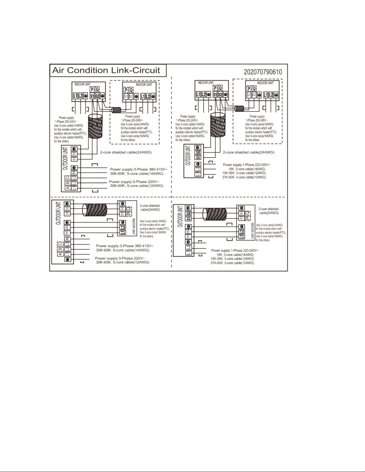
12 Field Wiring
36,000 and 48,000 BTU Models
55
Page 59
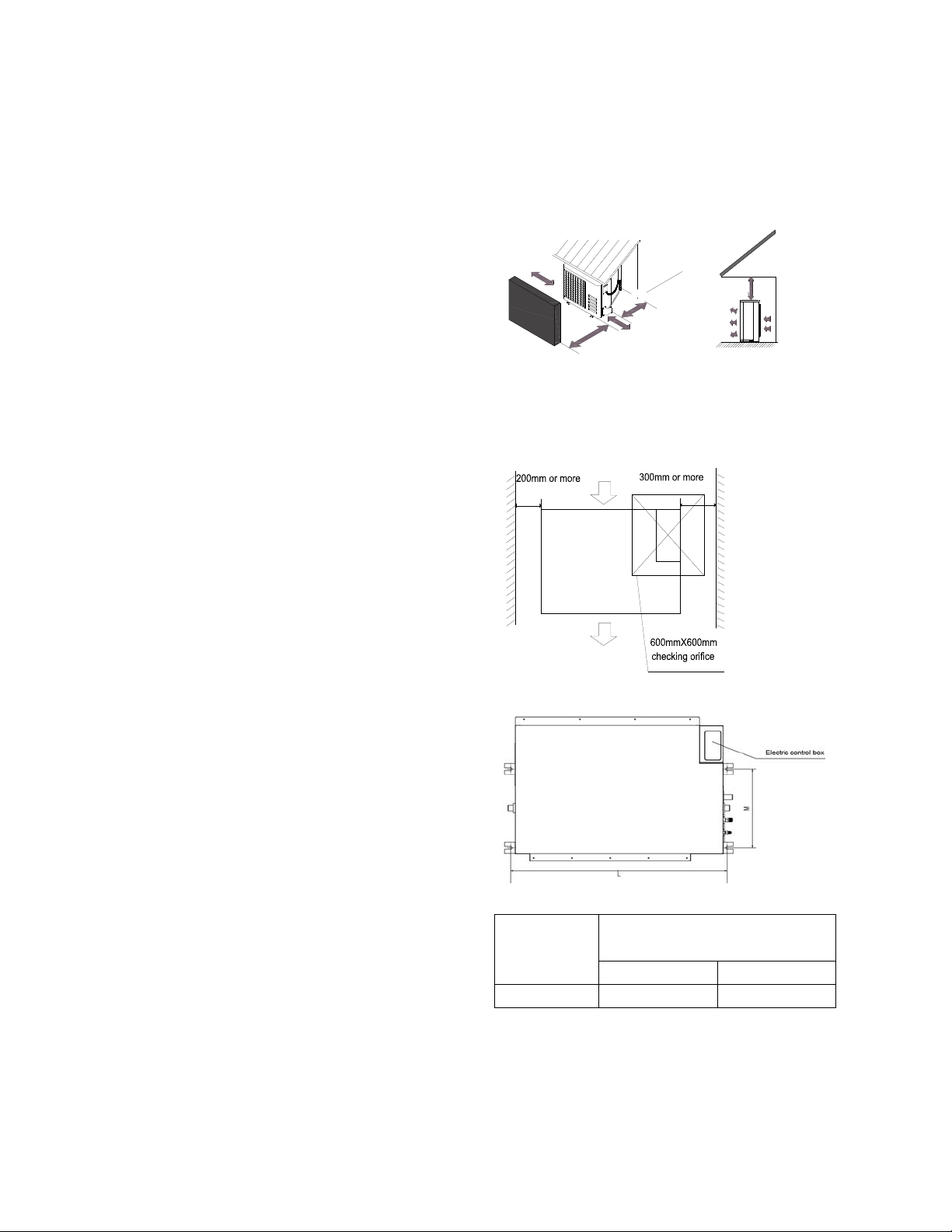
12 Installation Details
12.1 Location selection
12.1.1 Indoor unit location selection
The place shall easily support the indoor
unit’s weight.
The place can ensure the indoor unit
installation and inspection.
The place can ensure the indoor unit
horizontally installed.
The place shall allow easy water drainage.
The place shall easily connect with the
outdoor unit.
The place where air circulation in the room
should be good.
There should not be any heat source or
steam near the unit.
There should not be any oil gas near the unit
There should not be any corrosive gas near
the unit
There should not be any salty air neat the
unit
There should not be strong electromagnetic
wave near the unit
There should not be inflammable materials
or gas near the unit
There should not be strong voltage vibration.
12.1.2
The place shall easily support the outdoor
Locate the outdoor unit as close to indoor
The piping length and height drop cannot
The place where the noise, vibration and
There is enough room for installation and
The air outlet and the air inlet are not
It is easy to install the connecting pipes and
There is no danger of fire due to leakage of
It should be a dry and well ventilation place
The support should be flat and horizontal
Do not install the outdoor unit in a dirty or
Outdoor unit location selection
unit’s weight.
unit as possible
exceed the allowable value.
outlet air do not disturb the neighbors.
maintenance.
impeded, and not face the strong wind.
cables.
inflammable gas.
severely polluted place, so as to avoid
blockage of the heat exchanger in the
outdoor unit.
If is built over the unit to prevent direct
sunlight, rain exposure, direct strong wend,
snow and other scraps accumulation, make
sure that heat radiation from the condenser
is not restricted.
More than 30cm/11.81in
F
e
n
c
e
o
b
o
s
r
t
a
c
l
e
s
More than 30cm/11.81in
More than 60cm/23.62in
More than 200cm/78.74in
More than
60cm/23.62in
(Service space
︶
12.2 Indoor unit installation
12.2.1 A5 duct indoor unit installation
12.2.1.1 Service space for indoor unit
12.2.1.2 Bolt pitch
Size of outline dimension mounted
Capacity(KBtu)
12 740 350
12.2.1.3 Install the pendant bolt
Select the position of installation hooks
according to the hook holes positions showed
in upper picture.
plug
L M
56
Page 60
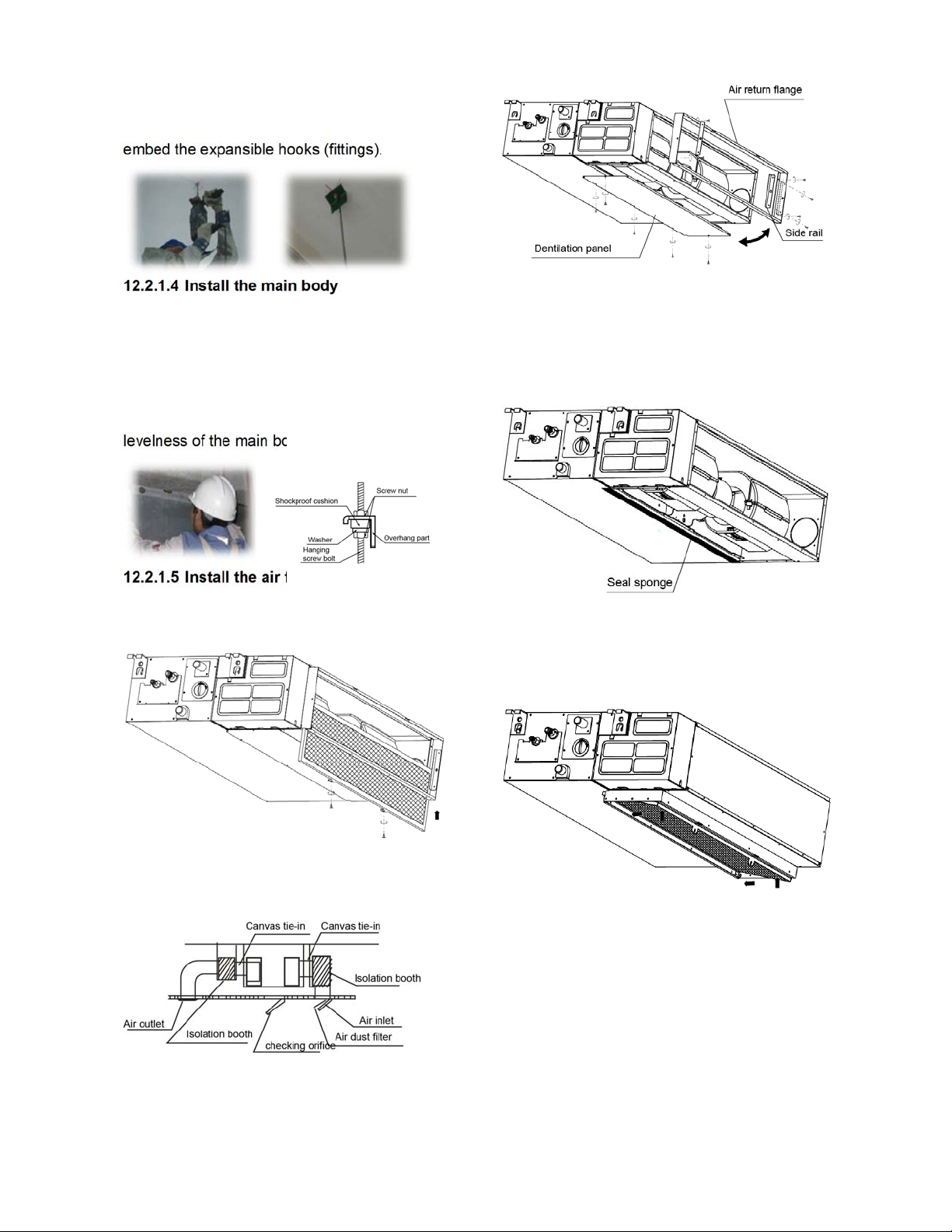
Drill four holes of Ø12mm, 45~50mm deep at
the selected positions on the ceiling. Then
embed the expansible hooks (fittings).
12.2.1.4 Install the main body
Make the 4 suspender through the 4 hanger of
the main body to suspend it. Adjust the
hexangular nuts on the four installation hooks
evenly, to ensure the balance of the body. Use
a leveling instrument to make sure the
levelness of the main body is within ±1°.
12.2.1.5 Install the air filter
Insert the air filter through the filter slot and fix it
with 2 screws.
② Stick the attached seal sponge as per the
indicating place in the following fig, and then
change the mounting positions of air return
panel and air return flange .
③ When install the filter mesh, please plug it
into flange inclined from air return opening, and
then push up.
12.2.1.6 Install the air duct
Please design the air duct as below
recommended picture
12.2.1.7 Change the air inlet direction
① Take off ventilation panel and flange, cut off
the staples at side rail.
④ The installation has finish, upon filter mesh
which fixing blocks have been insert to the
flange positional holes.
57
Page 61
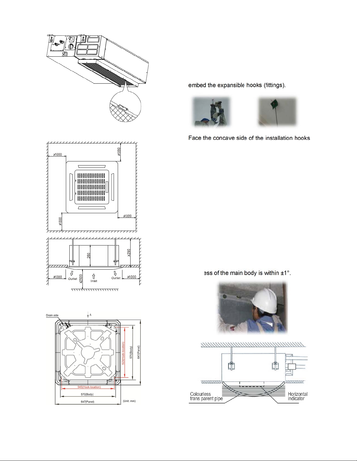
12.2.2 Cassette indoor unit installation
12.2.2.1 Service space for indoor unit
Select the position of installation hooks
according to the hook holes positions showed
in upper picture.
Drill four holes of Ø12mm, 45~50mm deep at
the selected positions on the ceiling. Then
embed the expansible hooks (fittings).
Face the concave side of the installation hooks
toward the expansible hooks. Determine the
length of the installation hooks from the height
of ceiling, then cut off the unnecessary part.
If the ceiling is extremely high, please
determine the length of the installation hook
depending on the real situation.
12.2.2.2 Bolt pitch
12.2.2.4 Install the main body
Make the 4 suspender through the 4 hanger of
the main body to suspend it. Adjust the
hexangular nuts on the four installation hooks
evenly, to ensure the balance of the body. Use
a leveling instrument to make sure the
levelness of the main body is within ±1°.
12.2.2.3 Install the pendant bolt
Adjust the position to ensure the gaps between
the body and the four sides of ceiling are even.
58
Page 62
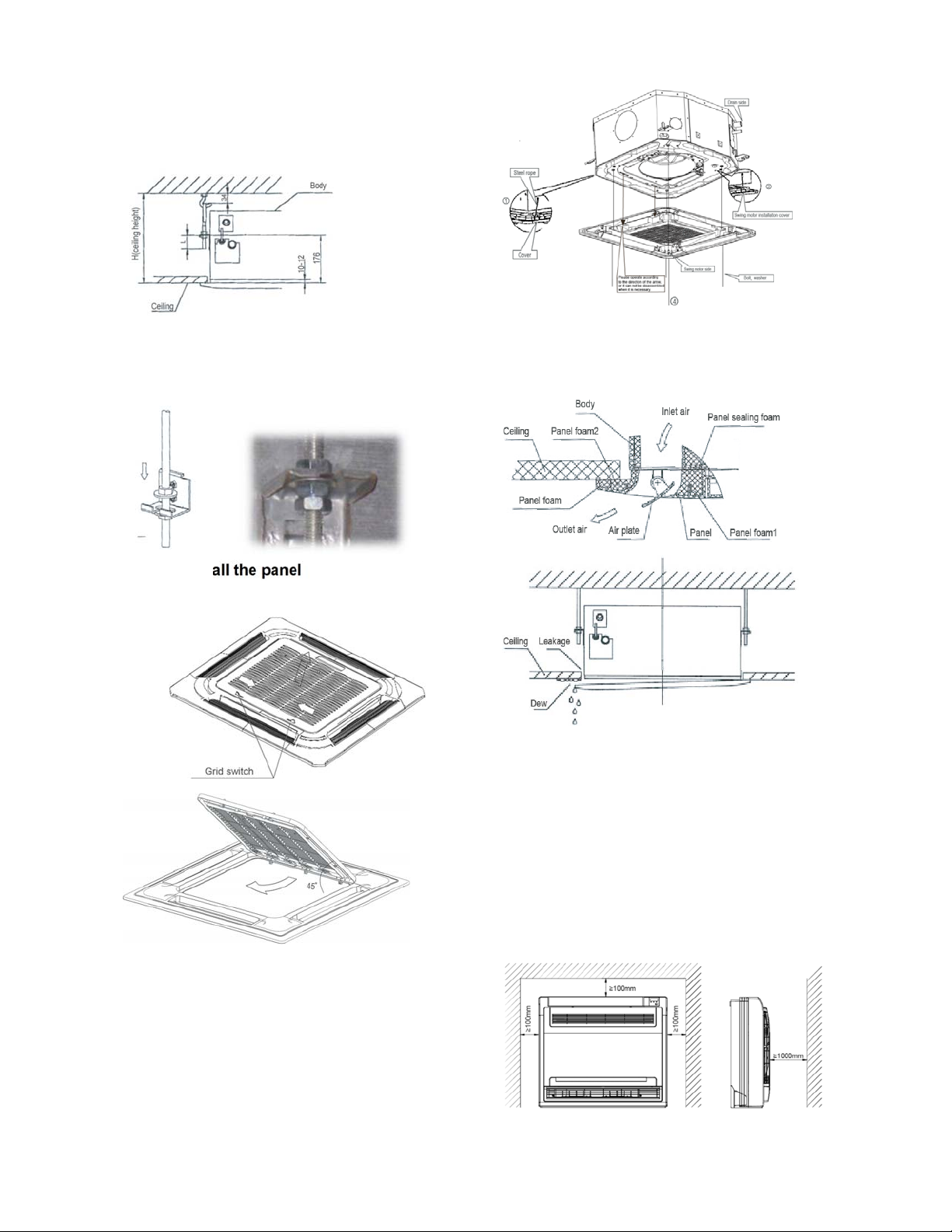
The body's lower part should sink into the
ceiling for 10~12 mm. In general, L is half of the
screw length of the installation hook.
Locate the air conditioner firmly by wrenching
the nuts after having adjusted the body's
position well.
12.2.2.5 Install the panel
Remove the grille
Tighten the screws under the panel hooks till
the panel closely stick on the ceiling to avoid
condensate water.
Hang the air-in grill to the panel, then connect
the lead terminator of the swing motor and that
of the control box with corresponding
terminators on the body respectively.
Hang the panel to the hooks on the mainbody.
Note: The panel shall be installed after the
wiring connected.
12.2.3 Console indoor unit installation
14.2.1.1 Service space for indoor unit
59
Page 63

12.2.3.2 Install the main body
Fix the hook with tapping screw onto the
wall
Hang the indoor unit on the hook.
(The bottom of body can touch with floor or
suspended, but the body must install vertically.)
Capacity
(Btu/h)
24K 983 220
36K 1200 220
48K 1565 220
D E
② Wall-mounted installation
14.2.1 Ceiling-floor unit installation
14.2.1.1 Service space for indoor unit
12.2.1.2 Bolt pitch
① Ceiling installation
3.4.1Install the pendant bolt
① Ceiling installation
Select the position of installation hooks according
to the hook holes positions showed in upper picture.
Drill four holes of Ø12mm, 45~50mm deep at the
selected positions on the ceiling. Then embed the
expansible hooks (fittings).
② Wall-mounted installation
Install the tapping screws onto the wall.(Refer to
picture below)
60
Page 64
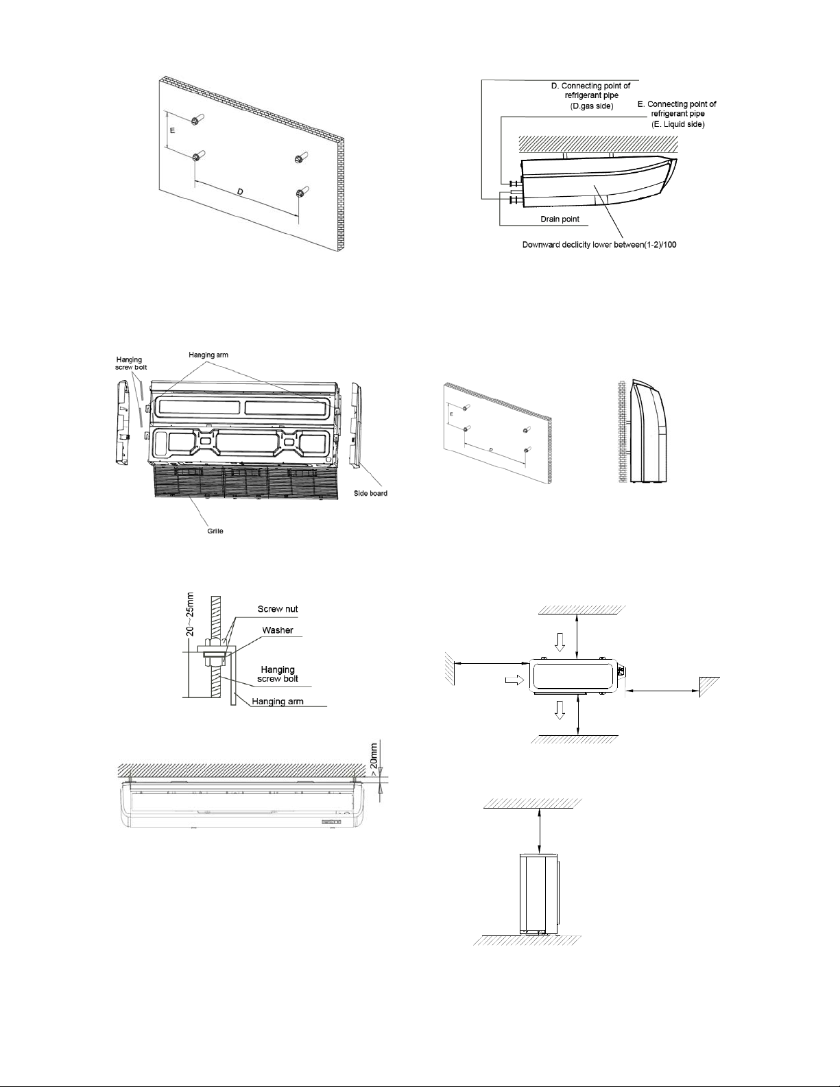
14.2.1.3 Install the main body
Ceiling installation (The only installation
①
method for the unit with drain pump)
Remove the side board and the grille.
Locate the hanging arm on the hanging screw bolt.
Prepare the mounting bolts on the unit.
Put the side panels and grilles back.
② Wall-mounted installation
Hang the indoor unit by insert the tapping screws
into the hanging arms on the main unit. (The bottom
of body can touch with floor or suspended, but the
body must install vertically.)
12.3 Outdoor unit installation
12.3.1 Service space for outdoor unit
(Wall or obstacle)
More than 30cm
(11.81in)
Air inlet
Air inlet
Air outlet
More than 30cm(11.81in)
Maintain channel
More than 60cm
(23.62in)
More than 200cm(78.74in)
More than 60cm
(23.62in)
12.3.2 Bolt pitch
61
Page 65
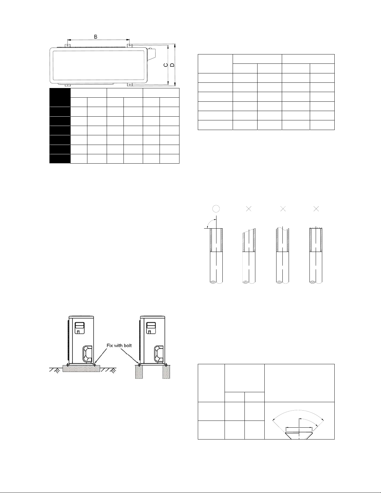
Model
9K 549 21.61 325 12.80 350 13.78
12K 549 21.61 325 12.80 350 13.78
18K 560 22.05 335 13.19 360 14.17
24K 640 25.20 405 15.94 448 17.64
36K 640 25.20 405 15.94 448 17.64
48K 634 24.96 404 15.91 448 17.64
B C D
mm inch mm inch mm inch
14.3.3 Install the Unit
Since the gravity center of the unit is not at its
physical center, so please be careful when
lifting it with a sling.
Never hold the inlet of the outdoor unit to
prevent it from deforming.
Do not touch the fan with hands or other
objects.
Do not lean it more than 45, and do not lay it
sidelong.
Make concrete foundation according to the
specifications of the outdoor units.
Fasten the feet of this unit with bolts firmly to
prevent it from collapsing in case of earthquake
or strong wind.
12.4 Refrigerant pipe installation
12.4.1 Maximum pipe length and height
drop
Considering the allowable pipe length and
height drop to decide the installation position.
Make sure the distance and height drop
between indoor and outdoor unit not exceeded
the date in the following table.
Model
9,000Btu/h 25 82.2 10 32.9
12,000Btu/h 25 82.2 10 32.9
18,000Btu/h 30 98.7 20 65.8
24,000Btu/h 50 164.5 25 82.2
36,000Btu/h 65 213.8 30 98.7
48,000Btu/h 65 213.8 30 98.7
Max. Length Max. Elevation
m Ft. m Ft.
12.4.2 The procedure of connecting pipes
1. Choose the pipe size according to the
specification table.
2. Confirm the cross way of the pipes.
3. Measure the necessary pipe length.
4. Cut the selected pipe with pipe cutter
Make the section flat and smooth.
o
90
Lean
Crude
Burr
5. Insulate the copper pipe
Before test operation, the joint parts should
not be heat insulated.
6. Flare the pipe
Insert a flare nut into the pipe before flaring
the pipe
According to the following table to flare the
pipe
Flare
Pipe
diameter
1/4"
(6.35)
3/8"
(9.52)
dimension A
(mm)
Min Max
8.3 8.7
12.0 12.4
Flare shape
90°
+
4
-
4
5
¡
ã
A
62
Page 66
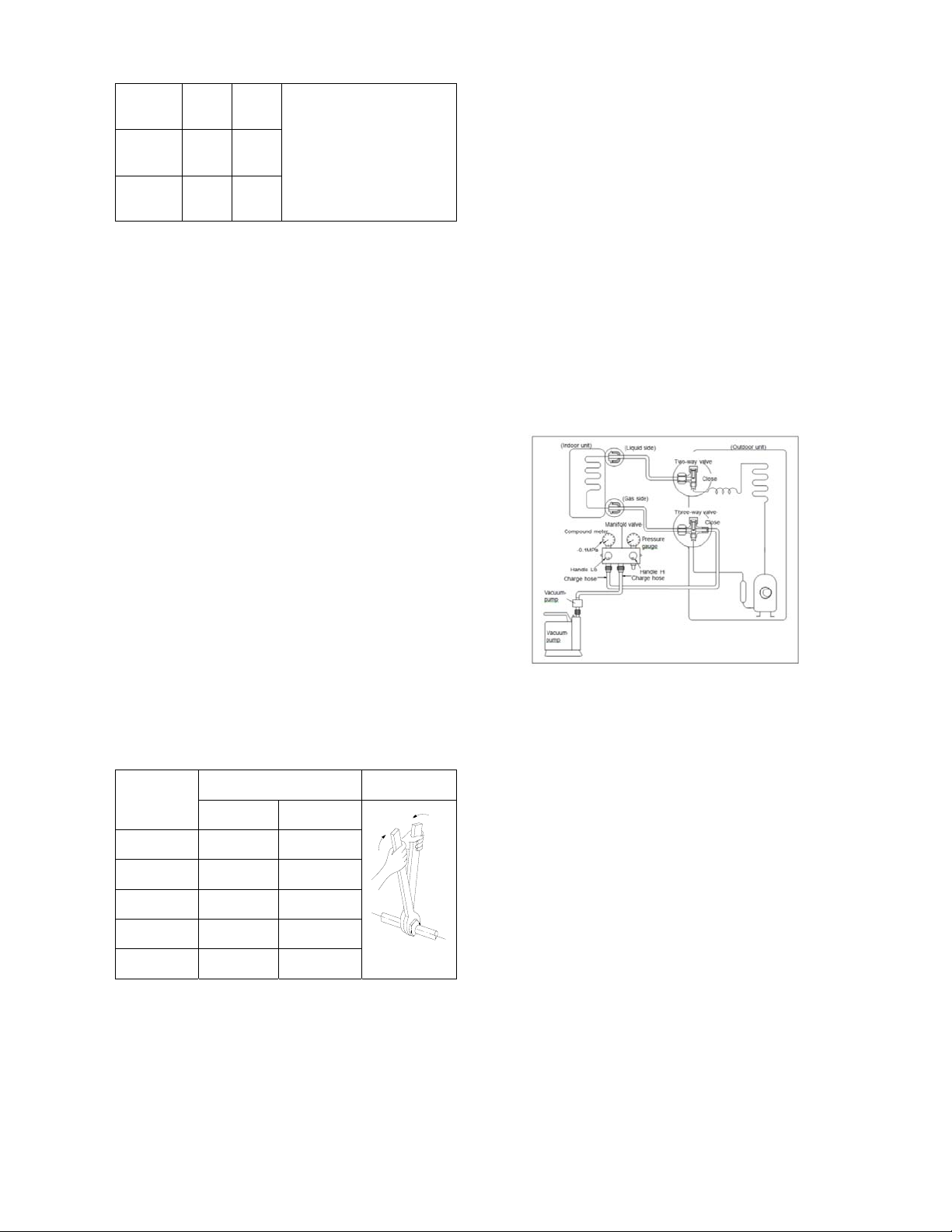
1/2"
(12.7)
5/8"
(15.9)
3/4" (19) 22.9 23.3
15.4 15.8
18.6 19.1
After flared the pipe, the opening part must
be seal by end cover or adhesive tape to
avoid duct or exogenous impurity come into
the pipe.
7. Drill holes if the pipes need to pass the
wall.
8. According to the field condition to bend the
pipes so that it can pass the wall smoothly.
9. Bind and wrap the wire together with the
insulated pipe if necessary.
10. Set the wall conduit
11. Set the supporter for the pipe.
12. Locate the pipe and fix it by supporter
For horizontal refrigerant pipe, the distance
between supporters should not be exceed
1m.
For vertical refrigerant pipe, the distance
between supporters should not be exceed
1.5m.
13. Connect the pipe to indoor unit and outdoor
unit by using two spanners.
Be sure to use two spanners and proper
torque to fasten the nut, too large torque
will damage the flare, and too small torque
may cause leakage. Refer the following
table for different pipe connection.
Pipe
Diameter
1/4" (6.35) 144~176 1420~1720
3/8" (9.52) 333~407 3270~3990
1/2" (12.7) 504~616 4950~6030
5/8" (15.9) 630~770 6180~7540
3/4" (19) 990~1210 9270~11860
Torque Sketch map
(kgf.cm) (N.cm)
12.4.3 Installation for the first time
Air and moisture in the refrigerant system have
undesirable effects as below:
● Pressure in the system rises.
● Operating current rises.
● Cooling or heating efficiency drops.
● Moisture in the refrigerant circuit may
freeze and block capillary tubing.
● Water may lead to corrosion of parts in the
refrigerant system.
Therefore, the indoor units and the pipes
between indoor and outdoor units must be leak
tested and evacuated to remove gas and
moisture from the system.
Gas leak check (Soap water method):
Apply soap water or a liquid neutral detergent
on the indoor unit connections or outdoor unit
connections by a soft brush to check for
leakage of the connecting points of the piping. If
bubbles come out, the pipes have leakage.
1. Air purging with vacuum pump
1) Completely tighten the flare nuts of the
indoor and outdoor units, confirm that both
the 2-way and 3-way valves are set to the
closed position.
2) Connect the charge hose with the push pin
of handle lo to the 3-way valves gas service
port..
3) Connect the charge hose of handle hi
connection to the vacuum pump.
4) Fully open the handle Lo of the manifold
valve.
5) Operate the vacuum pump to evacuate.
6) Make evacuation for 30 minutes and check
whether the compound meter indicates
-0.1Mpa (14.5Psi). If the meter does not
indicate -0.1Mpa (14.5Psi) after pumping 30
minutes, it should be pumped 20 minutes
more. If the pressure can’t achieve -0.1Mpa
(14.5Psi) after pumping 50 minutes, please
check if there are some leakage points.
Fully close the handle Lo valve of the
manifold valve and stop the operation of the
63
Page 67
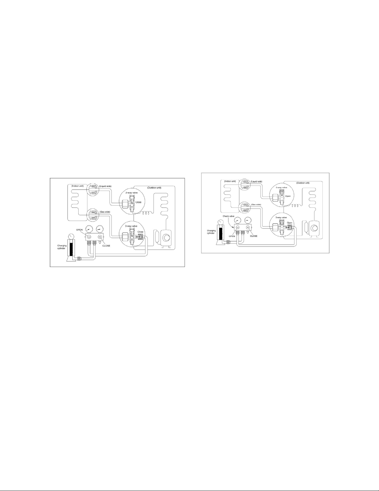
vacuum pump. Confirm that the gauge
needle does not move (approximately 5
minutes after turning off the vacuum pump).
7) Turn the flare nut of the 3-way valves about
45° counterclockwise for 6 or 7seconds
after the gas coming out, then tighten the
flare nut again. Make sure the pressure
display in the pressure indicator is a little
higher than the atmosphere pressure. Then
remove the charge hose from the 3 way
valve.
8) Fully open the 2 way valve and 3 way
valve and securely tighten the cap of the 3
way valve.
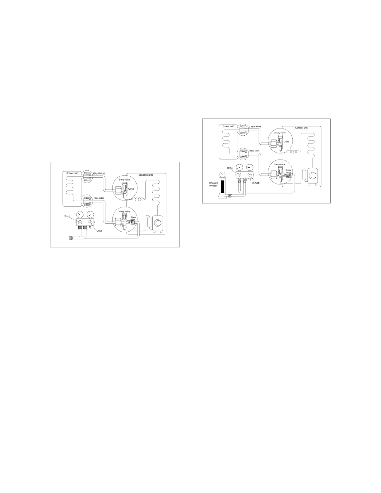
2. Air purging by refrigerant
the gauge indicates 0.3Mpa (43.5Psi) to 0.5
Mpa (72.5Psi).
6). Disconnect the charge set and the charging
cylinder, and set the 2-way and 3-way valves to
the open position.
Be sure to use a hexagonal wrench to operate
the valve stems.
7). Mount the valve stems nuts and the service
port cap.
Be sure to use a torque wrench to tighten the
service port cap to a torque 18N·m.
Be sure to check the gas leakage.
12.4.4 Adding the refrigerant after running
the system for many years
Procedure:
1). Confirm that both the 2-way and 3-way
valves are set to the closed position.
2). Connect the charge set and a charging
cylinder to the service port of the 3-way valve.
3). Air purging.
Open the valves on the charging cylinder and
the charge set. Purge the air by loosening the
flare nut on the 2-way valve approximately 45’
for 3 seconds then closing it for 1 minute; repeat
3 times.
After purging the air, use a torque wrench to
tighten the flare nut on the 2-way valve.
4). Check the gas leakage.
Check the flare connections for gas leakage.
5). Discharge the refrigerant.
Close the valve on the charging cylinder and
discharge the refrigerant by loosening the flare
nut on the 2-way valve approximately 45’ until
Procedure
1). Connect the charge hose to the 3-way
service port, open the 2-way valve and the
3-way valve.
Connect the charge hose to the valve at the
bottom of the cylinder. If the refrigerant is
R410A, make the cylinder bottom up to ensure
liquid charge.
2). Purge the air from the charge hose.
Open the valve at the bottom of the cylinder
and press the check valve on the charge set to
purge the air (be careful of the liquid
refrigerant).
3) Put the charging cylinder onto the electronic
scale and record the weight.
4) Operate the air conditioner at the cooling
mode.
5) Open the valves (Low side) on the charge set
and charge the system with liquid refrigerant.
6).When the electronic scale displays the
proper weight (refer to the gauge and the
64
Page 68
pressure of the low side), disconnect the charge
hose from the 3-way valve’s service port
immediately and turn off the air conditioner
before disconnecting the hose.
7). Mount the valve stem caps and the service
port
Use torque wrench to tighten the service port
cap to a torque of 18N.m.
Be sure to check for gas leakage.
12.4.5 Re-installation while the indoor unit
need to be repaired
1. Collecting the refrigerant into the outdoor
unit
Procedure
1). Confirm that both the 2-way and 3-way
valves are set to the opened position
Remove the valve stem caps and confirm that
the valve stems are in the opened position.
Be sure to use a hexagonal wrench to operate
the valve stems.
2). Connect the charge hose with the push pin
of handle lo to the 3-way valves gas service
port.
3). Air purging of the charge hose.
Open the handle Lo valve of the manifold valve
slightly to purge air from the charge hose for 5
seconds and then close it quickly.
4). Set the 2-way valve to the close position.
5). Operate the air conditioner at the cooling
cycle and stop it when the gauge indicates
0.1Mpa (14.5Psi).
6). Set the 3-way valve to the closed position
immediately
Do this quickly so that the gauge ends up
indicating 0.3Mpa (43.5Psi) to 0.5 Mpa
(72.5Psi).
Disconnect the charge set, and tighten the
2-way and 3-way valve’s stem nuts.
Use a torque wrench to tighten the 3-way valves
service port cap to a torque of 18N.m.
Be sure to check for gas leakage.
2. Air purging by the refrigerant
Procedure:
1). Confirm that both the 2-way and 3-way
valves are set to the closed position.
2). Connect the charge set and a charging
cylinder to the service port of the 3-way valve
Leave the valve on the charging cylinder closed.
3). Air purging.
Open the valves on the charging cylinder and
the charge set. Purge the air by loosening the
flare nut on the 2-way valve approximately 45’
for 3 seconds then closing it for 1 minute; repeat
3 times.
After purging the air, use a torque wrench to
tighten the flare nut on the 2-way valve.
4). Check the gas leakage
Check the flare connections for gas leakage.
5). Discharge the refrigerant.
Close the valve on the charging cylinder and
discharge the refrigerant by loosening the flare
nut on the 2-way valve approximately 45’ until
the gauge indicates 0.3Mpa (43.5Psi) to 0.5
Mpa (72.5Psi).
6). Disconnect the charge set and the charging
cylinder, and set the 2-way and 3-way valves to
the open position
Be sure to use a hexagonal wrench to operate
the valve stems.
65
Page 69
7). Mount the valve stems nuts and the service
port cap
Be sure to use a torque wrench to tighten the
service port cap to a torque 18N.m.
Be sure to check the gas leakage.
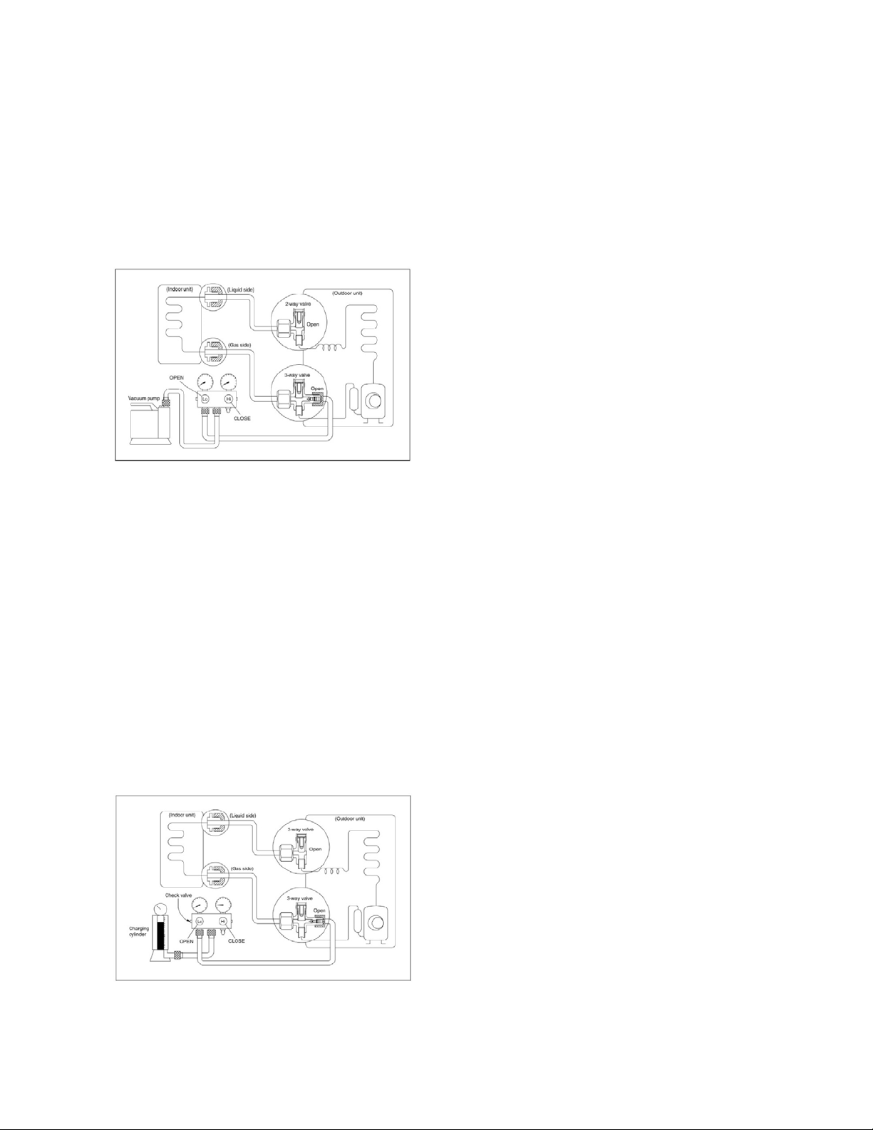
12.4.6 Re-installation while the outdoor unit
need to be repaired
1. Evacuation for the whole system
Procedure:
1). Confirm that both the 2-way and 3-way
valves are set to the opened position.
2). Connect the vacuum pump to 3-way valve’s
service port.
3). Evacuation for approximately one hour.
Confirm that the compound meter indicates
-0.1Mpa (14.5Psi).
4). Close the valve (Low side) on the charge set,
turn off the vacuum pump, and confirm that the
gauge needle does not move (approximately 5
minutes after turning off the vacuum pump).
5). Disconnect the charge hose from the
vacuum pump.
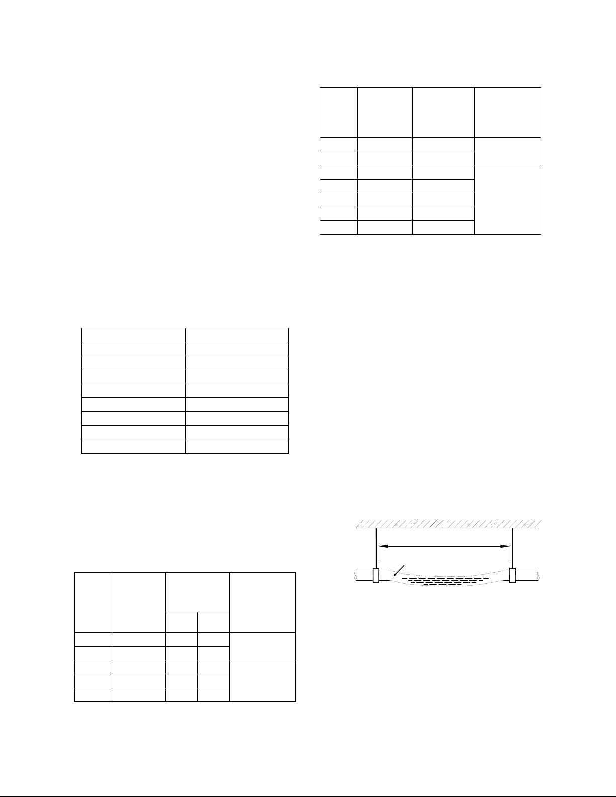
2. Refrigerant charging
1). Connect the charge hose to the charging
cylinder, open the 2-way valve and the 3-way
valve
Connect the charge hose which you
disconnected from the vacuum pump to the
valve at the bottom of the cylinder. If the
refrigerant is R410A, make the cylinder bottom
up to ensure liquid charge.
2). Purge the air from the charge hose
Open the valve at the bottom of the cylinder
and press the check valve on the charge set to
purge the air (be careful of the liquid
refrigerant).
3) Put the charging cylinder onto the electronic
scale and record the weight.
4). Open the valves (Low side) on the charge
set and charge the system with liquid refrigerant
If the system cannot be charge with the
specified amount of refrigerant, or can be
charged with a little at a time (approximately
150g each time) , operating the air conditioner
in the cooling cycle; however, one time is not
sufficient, wait approximately 1 minute and then
repeat the procedure.
5).When the electronic scale displays the
proper weight, disconnect the charge hose from
the 3-way valve’s service port immediately
If the system has been charged with liquid
refrigerant while operating the air conditioner,
turn off the air conditioner before disconnecting
the hose.
6). Mounted the valve stem caps and the
service port. Use torque wrench to tighten the
service port cap to a torque of 18N.m. Be sure
to check for gas leakage.
Procedure:
12.5 Drainage pipe installation
Install the drainage pipe as shown below and
take measures against condensation.
Improperly installation could lead to leakage
and eventually wet furniture and belongings.
12.5.1 Installation principle
Ensure at least 1/100 slope of the drainage
pipe
66
Page 70
Adopt suitable pipe diameter
Adopt nearby condensate water discharge
12.5.2 Key points of drainage water pipe
installation
1. Considering the pipeline route and
elevation
Before installing condensate water pipeline,
determine its route and elevation to avoid
intersection with other pipelines and ensure
slope is straight.
2. Drainage pipe selection
The drainage pipe diameter shall not small
than the drain hose of indoor unit
According to the water flowrate and
drainage pipe slope to choose the suitable
pipe, the water flowrate is decided by the
capacity of indoor unit.
Relationship between water flowrate and
capacity of indoor unit
Capacity (x1000Btu) Water flowrate (l/h)
12 2.4
18 4
24 6
30 7
36 8
42 10
48 12
60 14
According to the above table to calculate the
total water flowrate for the confluence pipe
selection.
For horizontal drainage pipe (The following
table is for reference)
Reference
PVC
pipe
PVC25 20 39 27
PVC32 25 70 50
PVC40 31 125 88
PVC50 40 247 175
PVC63 51 473 334
value of
inner
diameter of
pipe (mm)
Allowable
maximum
water flowrate
(l/h)
Slope
1/50
Slope
1/100
Remark
For branch
pipe
Could be used
for confluence
pipe
Attention: Adopt PVC40 or bigger pipe to be the
main pipe.
For Vertical drainage pipe (The following
table is for reference)
Reference
PVC
pipe
PVC25 20 220
PVC32 25 410
PVC40 31 730
PVC50 40 1440
PVC63 51 2760
PVC75 67 5710
PVC90 77 8280
value of
inner
diameter of
pipe (mm)
Allowable
maximum
water
flowrate (l/h)
Remark
For branch
pipe
Could be used
for confluence
pipe
Attention: Adopt PVC40 or bigger pipe to be the
main pipe.
3. Individual design of drainage pipe
system
The drainage pipe of air conditioner shall
be installed separately with other sewage
pipe, rainwater pipe and drainage pipe in
building.
The drainage pipe of the indoor unit with
water pump should be apart from the one
without water pump.
4. Supporter gap of drainage pipe
In general, the supporter gap of the
drainage pipe horizontal pipe and vertical
pipe is respectively 1m~1.5m (3.28~4.92ft)
and 1.5m~2.0m(4.95~6.56ft).
Each vertical pipe shall be equipped with
not less than two hangers.
Overlarge hanger gap for horizontal pipe
shall create bending, thus leading to air
block.
Too long distance
Gas bag
5. The horizontal pipe layout should avoid
converse flow or bad flow
67
Page 71
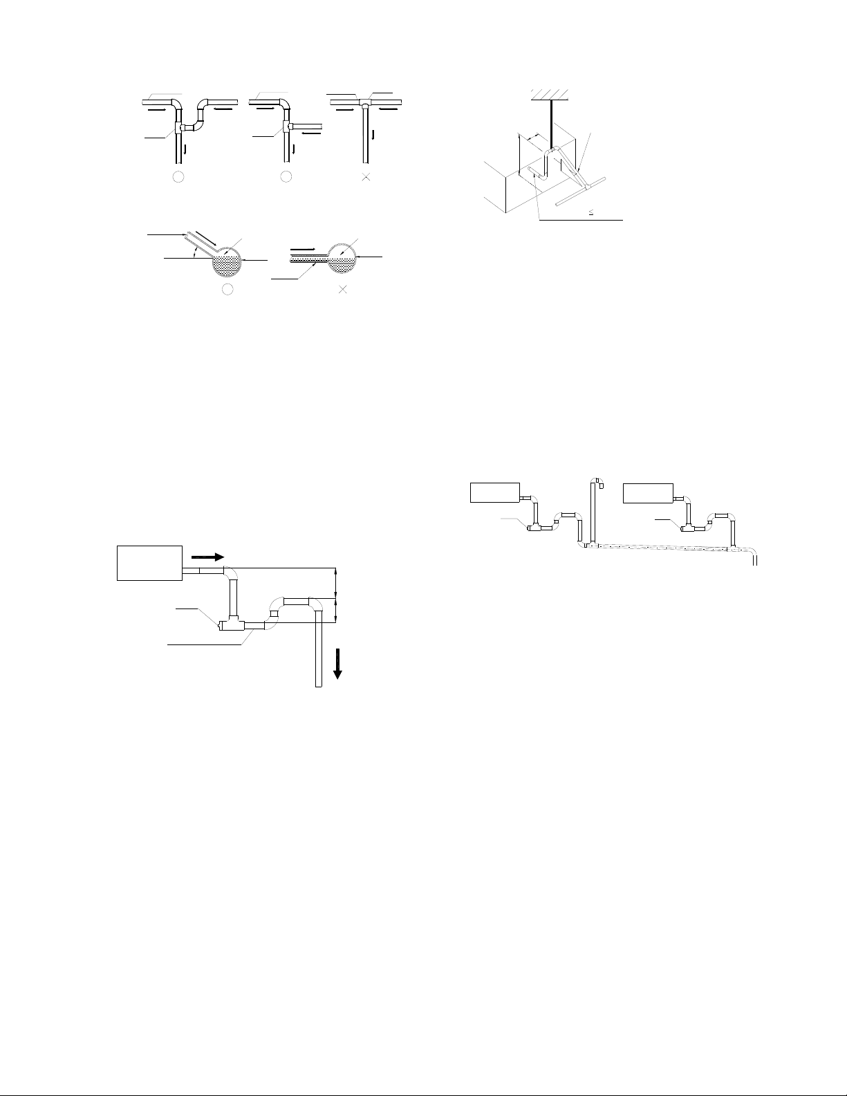
Drainage pipe
Water flow
Drain
Drainage pipe
Water flow
tee
Water flow
Water flow
Drain
tee
Drainage pipe
Water flow
Water flow
Water flow
Drain
Water flow
Water flow
tee
Hanger
A
B
Down incline pipe
A:Length of horizontal pipe≤150mm
B: Lift height
≤the pump head of water pump
Branch pipe
Keep a certain degree
Water flow
Gas
Main pipe
Branch pipe
Water flow
Gas
Main pipe
The correct installation will not cause
converse water flow and the slope of the
branch pipes can be adjusted freely
The false installation will cause converse
water flow and the slope of the branch pipe
cannot be adjusted.
6. Water storage pipe setting
If the indoor unit has high extra static
pressure and without water pump to
elevate the condensate water, such as high
extra static pressure duct unit , the water
storage pipe should be set to avoid
converse flow or blow water phenomena.
Indoor unit
More than 50mm
Plug
Water storage pipe
More than 25mm
7. Lifting pipe setting of indoor unit with
water pump
The length of lifting pipe should not exceed
the pump head of indoor unit water pump.
The drainage pipe should be set down
inclined after the lifting pipe immediately to
avoid wrong operation of water level switch.
Refer the following picture for installation
reference.
Flexible pipe 300mm
8. Blowhole setting
For the concentrated drainage pipe system,
there should design a blowhole at the
highest point of main pipe to ensure the
condensate water discharge smoothly.
The air outlet shall face down to prevent dirt
entering pipe.
Each indoor unit of the system should be
installed it.
The installation should be considering the
convenience for future cleaning.
Blowhole
Indoor unit
Plug
Indoor unit
Plug
9. The end of drainage pipe shall not
contact with ground directly.
12.5.3 Drainage test
12.5.3.1. Water leakage test
After finishing the construction of drainage pipe
system, fill the pipe with water and keep it for
24 hours to check whether there is leakage at
joint section.
12.5.3.2. Water discharge test
1. Natural drainage mode(the indoor unit with
outdoor drainage pump)
Infuse above 600ml water through water test
hole slowly into the water collector, observe
whether the water can discharge through the
transparent hard pipe at drainage outlet.
68
Page 72
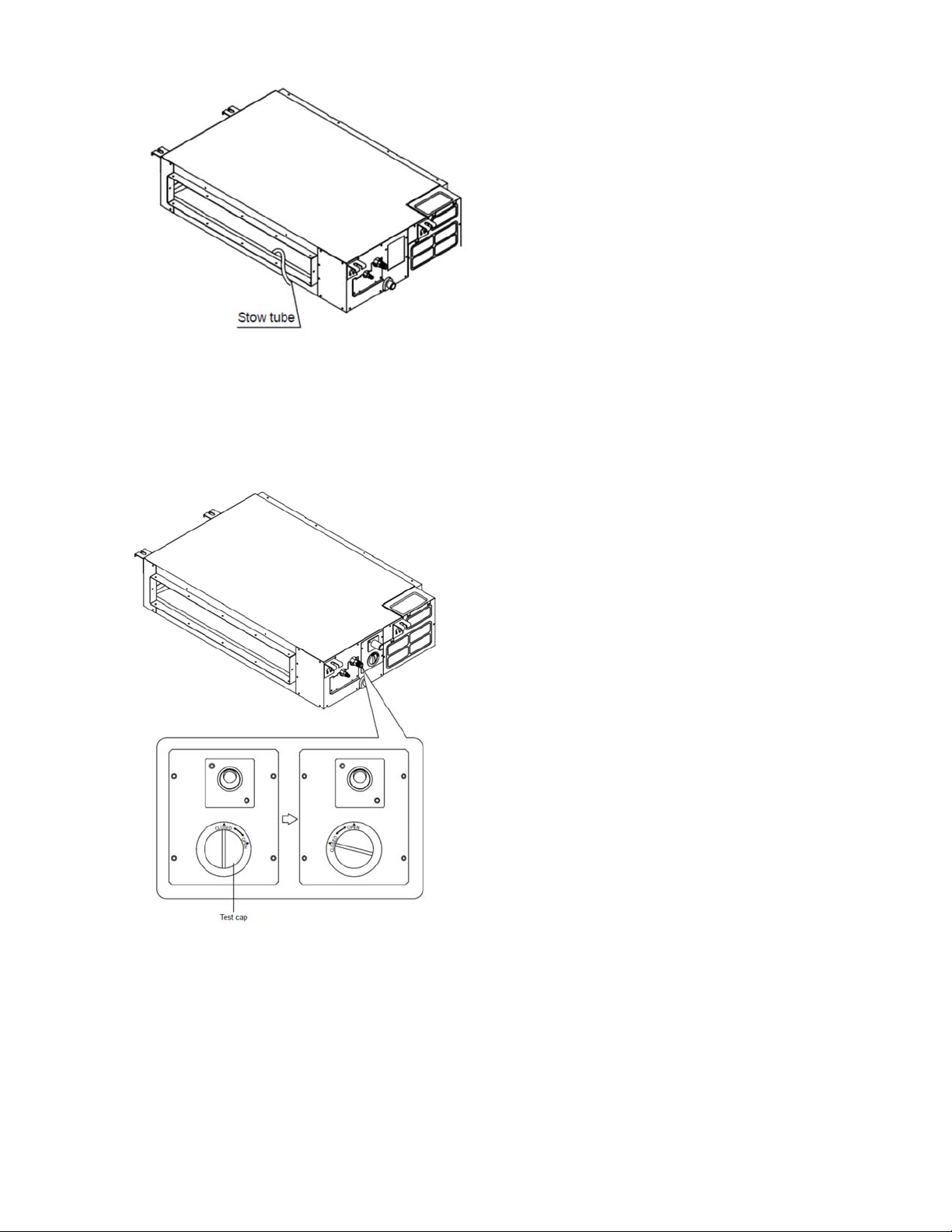
2. Pump drainage mode
2.1 Disconnect the plug of water level switch,
remove the cover of water test hole and slowly
infuse about 2000ml water through the water
test hole, be sure that the water will not touch
the motor of drainage pump.
drainage outlet. (In light of the length of
drainage pipe, water shall be discharged
about 1 minute delayed)
2.3 Stop the operation of air conditioner, power
off the power supply and put the cover of
water test hole back to the original place.
a. After stopped the air conditioner 3 minutes,
check whether there is anything abnormal.
If drainage pipes have not been distributed
properly, over back-flow water shall cause
the flashing of alarm indicator at
remote-controlled receiving board and
even water shall run over the water
collector.
b. Continuously infusing water until water
level alarmed, check whether the drainage
pump could discharge water at once. If
water level does not decline under warning
water level 3 minutes later, it shall cause
shutdown of unit. When this situation
happens, the normal startup only can be
recovered by turning down power supply
and eliminating accumulated water.
2.2 Power on and let the air conditioner
operate for cooling. Check operation status
of drainage pump, and then connect the
plug of water level switch, check the
operation sound of water pump and
observe whether the water can discharge
through the transparent hard pipe at
Note: Drain plug at the main water-containing
plate is used for eliminating accumulated water
in water-containing plate when maintaining air
conditioner fault. During normal operation, the
plug shall be filled in to prevent leakage.
12.5.4 Insulation work of drainage pipe
Refer the introduction to the insulation
engineering parts.
12.6 Vacuum Drying and Leakage
Checking
12.6.1 Purpose of vacuum drying
Eliminating moisture in system to prevent
the phenomena of ice-blockage and copper
oxidation.
69
Page 73

Ice-blockage shall cause abnormal
operation of system, while copper oxide
shall damage compressor.
Eliminating the non-condensable gas (air)
in system to prevent the components
oxidizing, pressure fluctuation and bad heat
exchange during the operation of system.
12.6.2 Selection of vacuum pump
The ultimate vacuum degree of vacuum
pump shall be -756mmHg or above.
Precision of vacuum pump shall reach
0.02mmHg or above.
12.6.3 Operation procedure for vacuum
drying
Due to different construction environment, two
kinds of vacuum drying ways could be chosen,
namely ordinary vacuum drying and special
vacuum drying.
1 Ordinary vacuum drying
When conduct first vacuum drying,
connect pressure gauge to the infusing
mouth of gas pipe and liquid pipe, and
keep vacuum pump running for 1hour
(vacuum degree of vacuum pump shall be
reached -755mmHg).
If the vacuum degree of vacuum pump
could not reach -755mmHg after 1 hour of
drying, it indicates that there is moisture or
leakage in pipeline system and need to go
on with drying for half an hour.
If the vacuum degree of vacuum pump still
could not reach -755mmHg after 1.5 hours
of drying, check whether there is leakage
source.
Leakage test: After the vacuum degree
reaches -755mmHg, stop vacuum drying
and keep the pressure for 1 hour. If the
indicator of vacuum gauge does not go up,
it is qualified. If going up, it indicates that
there is moisture or leak source.
2 Special vacuum drying
The special vacuum drying method shall be
adopted when:
Finding moisture during flushing refrigerant
pipe.
Conducting construction on rainy day,
because rain water might penetrated into
pipeline.
Construction period is long, and rain water
might penetrated into pipeline.
Rain water might penetrate into pipeline
during construction.
Procedures of special vacuum drying are as
follows:
Vacuum drying for 1 hour.
Vacuum damage, filling nitrogen to reach
0.5Kgf/cm2 .
Because nitrogen is dry gas, vacuum
damage could achieve the effect of
vacuum drying, but this method could not
achieve drying thoroughly when there is
too much moisture. Therefore, special
attention shall be drawn to prevent the
entering of water and the formation of
condensate water.
Vacuum drying again for half an hour.
If the pressure reaches -755mmHg,start
to pressure leakage test. If it cannot reach
the value, repeat vacuum damage and
vacuum drying again for 1 hour.
Leakage test: After the vacuum degree
reaches -755mmHg, stop vacuum drying
and keep the pressure for 1 hour. If the
indicator of vacuum gauge does not go up,
it is qualified. If going up, it indicates that
there is moisture or leak source.
12.7 Additional refrigerant charge
70
Page 74
After the vacuum drying process is carried
out, the additional refrigerant charge
process needs to be performed.
The outdoor unit is factory charged with
refrigerant. The additional refrigerant
charge volume is decided by the diameter
and length of the liquid pipe between indoor
and outdoor unit. Refer the following
formula to calculate the charge volume.
Diameter of
liquid pipe
(mm)
Formula V=15g/m×(L-7.5) V=30g/m×(L-7.5)
Φ6.35 Φ9.52
V: Additional refrigerant charge volume (g).
L: The length of the liquid pipe (m).
Note:
Refrigerant may only be charged after
performed the vacuum drying process.
Always use gloves and glasses to protect
your hands and eyes during the charge
work.
Use electronic scale or fluid infusion
apparatus to weight refrigerant to be
recharged. Be sure to avoid extra
refrigerant charged, it may cause liquid
hammer of the compressor or protections.
Use supplementing flexible pipe to connect
refrigerant cylinder, pressure gauge and
outdoor unit. And The refrigerant should be
charged in liquid state. Before recharging,
The air in the flexible pipe and manifold
gauge should be exhausted.
After finished refrigerant recharge process,
check whether there is refrigerant leakage
at the connection joint part. (Using gas
leakage detector or soap water to detect).
2 Purpose of refrigerant pipe insulation
During operation, temperature of gas pipe
and liquid pipe shall be over-heating or
over-cooling extremely. Therefore, it is
necessary to carry out insulation; otherwise
it shall debase the performance of unit and
burn compressor.
Gas pipe temperature is very low during
cooling. If insulation is not enough, it shall
form dew and cause leakage.
Temperature of gas pipe is very high
(generally 50-100 ℃ ) during heating.
Insulation work must be carried out to
prevent hurt by carelessness touching.
3 Insulation material selection for
refrigerant pipe
The burning performance should over
120℃
According to the local law to choose
insulation materials
The thickness of insulation layer shall be
above 10mm.If in hot or wet environment
place, the layer of insulation should be
thicker accordingly.
4 Installation highlights of insulation
construction
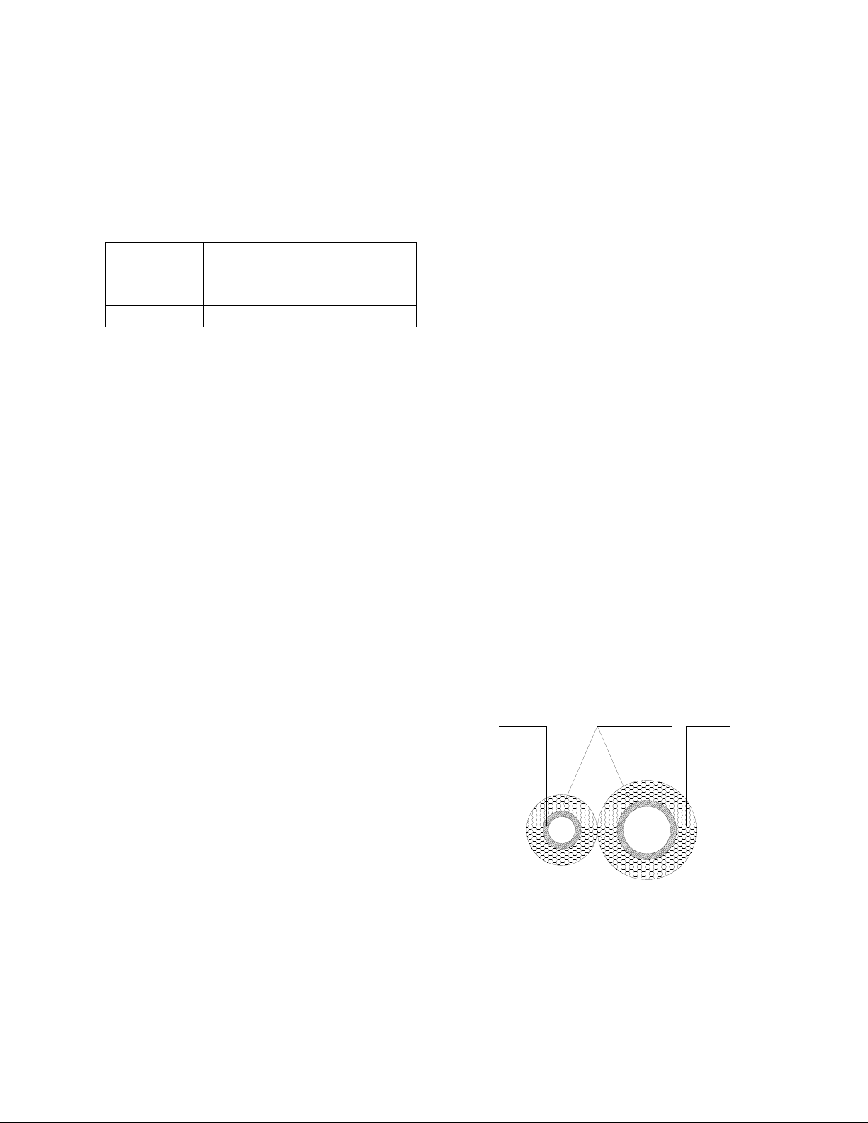
Gas pipe and liquid pipe shall be insulated
separately, if the gas pipe and liquid pipe
were insulated together; it will decrease the
performance of air conditioner.
Liquid pipe Insulation meterial
Gas pipe
12.8 Engineering of insulation
12.8.1 Insulation of refrigerant pipe
1 Operational procedure of refrigerant
pipe insulation
Cut the suitable pipe → insulation (except joint
section)
connection
joint parts
→ flare the pipe → piping layout and
→ vacuum drying → insulate the
The insulation material at the joint pipe
shall be 5~10cm longer than the gap of the
insulation material.
The insulation material at the joint pipe
shall be inserted into the gap of the insulation
material.
71
Page 75

The insulation material at the joint pipe
shall be banded to the gap pipe and liquid pipe
tightly.
The linking part should be use glue to paste
together
Be sure not bind the insulation material
over-tight, it may extrude out the air in the
material to cause bad insulation and cause
easy aging of the material.
12.8.2 Insulation of drainage pipe
1 Operational procedure of refrigerant
pipe insulation
Select the suitable pipe
joint section)
drainage test→ insulate the joint parts
2 Purpose of drainage pipe insulation
The temperature of condensate drainage water
is very low. If insulation is not enough, it shall
form dew and cause leakage to damage the
house decoration.
3 Insulation material selection for
drainage pipe
The insulation material should be flame
retardant material, the flame retardancy of
the material should be selected according
to the local law.
Thickness of insulation layer is usually
above 10mm.
Use specific glue to paste the seam of
insulation material, and then bind with
adhesive tape. The width of tape shall not
be less than 5cm. Make sure it is firm and
avoid dew.
4 Installation and highlights of insulation
construction
The single pipe should be insulated before
connecting to another pipe, the joint part
should be insulated after the drainage test.
There should be no insulation gap between
the insulation material.
→ piping layout and connection→
→ insulation (except
12.9 Engineering of electrical wiring
1 Highlights of electrical wiring
installation
All field wiring construction should be
finished by qualified electrician.
Air conditioning equipment should be
grounded according to the local electrical
regulations.
Current leakage protection switch should
be installed.
Do not connect the power wire to the
terminal of signal wire.
When power wire is parallel with signal wire,
put wires to their own wire tube and remain
at least 300mm gap.
According to table in indoor part named
“the specification of the power” to choose
the wiring, make sure the selected wiring
not small than the date showing in the
table.
Select different colors for different wire
according to relevant regulations.
Do not use metal wire tube at the place with
acid or alkali corrosion, adopt plastic wire
tube to replace it.
There must be not wire connect joint in the
wire tube If joint is a must, set a connection
box at the place.
The wiring with different voltage should not
be in one wire tube.
Ensure that the color of the wires of outdoor
and the terminal No. are same as those of
indoor unit respectively.
12.10 Test operation
1 The test operation must be carried out
after the entire installation has been
completed.
2 Please confirm the following points
before the test operation.
The indoor unit and outdoor unit are
installed properly.
Tubing and wiring are correctly completed.
The refrigerant pipe system is
leakage-checked.
The drainage is unimpeded.
The ground wiring is connected correctly.
The length of the tubing and the added
stow capacity of the refrigerant have been
recorded.
The power voltage fits the rated voltage of
the air conditioner.
There is no obstacle at the outlet and inlet
of the outdoor and indoor units.
72
Page 76

The gas-side and liquid-side stop values
are both opened.
The air conditioner is pre-heated by turning
on the power.
3 Test operation
Set the air conditioner under the mode of
"COOLING" by remote controller, and check
the following points.
Indoor unit
Whether the switch on the remote controller
works well.
Whether the buttons on the remote
controller works well.
Whether the air flow louver moves
normally.
Whether the room temperature is adjusted
well.
Whether the indicator lights normally.
Whether the temporary buttons works well.
Whether the drainage is normal.
Whether there is vibration or abnormal
noise during operation.
Outdoor unit
Whether there is vibration or abnormal
noise during operation.
Whether the generated wind, noise, or
condensed of by the air conditioner have
influenced your neighborhood.
Whether any of the refrigerant is leaked.
73
Page 77
13. Operation Characteristics
Temperature
Mode
Room temperature
Outdoor temperature
(Entry level)
Outdoor temperature
(E-Star level)
Outdoor temperature
(Hyper heat)
(-15℃~50℃(5℉~122℉):For
Cooling operation Heating operation Drying operation
17℃~32℃(62℉~90℉)
0℃~50℃
(32℉~122℉)
the models with low temperature
cooling system)
-25℃~50℃(-13℉~122℉)
-30℃~50℃(-22℉~122℉)
0℃~30℃
(32℉~86℉)
-15℃~30℃
(5℉~86℉)
-25℃~30℃
(-13℉~86℉)
-30℃~50℃
(-22℉~122℉)
10℃~32℃
(50℉~90℉)
0℃~50℃
(32℉~122℉)
CAUTION:
1. If the air conditioner is used beyond the above conditions, certain safety protection features may
come into operation and cause the unit to operate abnormally.
2. The room relative humidity should be less than 80%. If the air conditioner operates beyond this
figure, the surface of the air conditioner may attract condensation. Please set the vertical air flow louver to
its maximum angle (vertically to the floor), and set HIGH fan mode.
3. The optimum performance will be achieved during this operating temperature zone.
74
Page 78
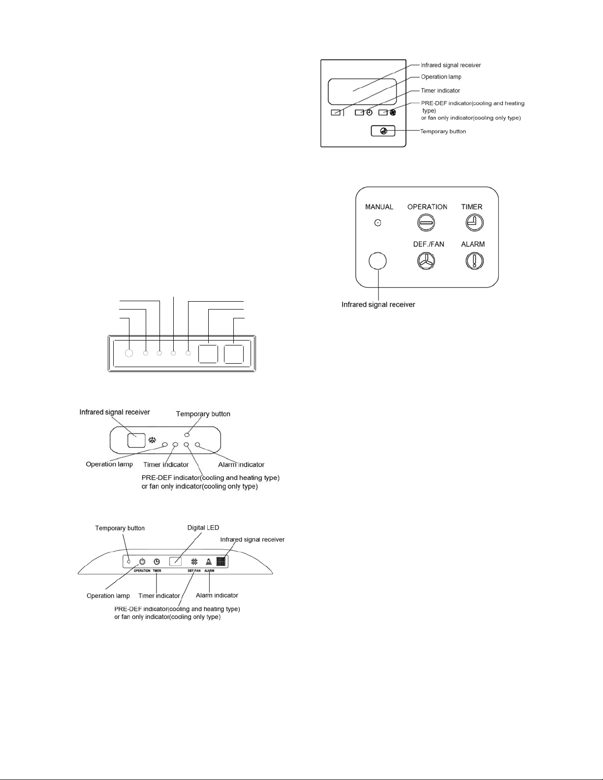
14. Electronic Function
14.1 Abbreviation
T1: Indoor room temperature
T2: Coil temperature of indoor heat exchanger
middle.
T2B: Coil temperature of indoor heat exchanger
outlet.
T3: Coil temperature of condenser
T4: Outdoor ambient temperature
T5: Compressor discharge temperature
Td: Target temperature
14.2 Display function
14.2.1 Icon explanation on indoor display board
(A5 Duct)
PRE-DEF indicator(cooling and heating type)
Timer indicator
Operation lamp
Temporary button
or fan only indicator(cooling only type)
DEF./FAN
TIMER
OPERATION
MANUAL
ALARM
14.2.2 Icon explanation on indoor display board
(Compact cassette).
14.2.3 Icon explanation on indoor display board
(slim Cassette).
14.2.3 Icon explanation on indoor display board
(Console).
Alarm indicator
Infrared signal receiver
Display digital tube
14.2.1 Icon explanation on indoor display board
(Ceiling Floor)
14.3 Main Protection
14.3.1 Three minutes delay at restart for
compressor
st
1 minute delay for the 1
minutes delay for others.
14.3.2 Temperature protection of
compressor top
The unit will stop working when the compressor
top temp. protector cut off, and will restart after
the compressor top temp. protector restart.
14.3.3 Temperature protection of
compressor discharge
When the compressor discharge temp. is
getting higher, the running frequency will be
limited as below rules:
---Compressor discharge temp. T5>115 ℃
(239°F) for 5s, compressor stops and restarts
up till T5<90℃(194°F)
---110<T5<115 ℃ (239°F), decrease the
frequency to the lower level every 2 minutes.
---105(221°F)<T5<110℃(230°F), keep running
at the current frequency.
----T5<105℃(221°F), no limit for frequency.
14.3.4 Fan speed is out of control
When indoor fan speed keeps too low (lower
than 300RPM) for 50s, the indoor fan will shut
off and restart 30s later, if protection happened
time stand-up and 3
75
Page 79
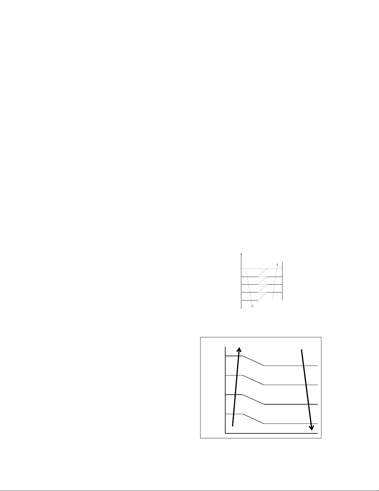
3 times when fan motor restarts continuously,
the unit will stop and the LED will display the
failure.
When outdoor fan speed keeps too low (lower
than 100RPM) or too high (higher than
1500RPM) for 60s, the unit will stop and the
LED will display the failure. Malfunction is
cleared 30s later.
14.3.5 Inverter module protection
The Inverter module has a protection function
about current, voltage and temperature. If these
protections happen, the corresponding code
will display on indoor unit and the unit will stop
working.
14.3.6 Indoor fan delayed open function
When the unit starts up, the louver will be active
immediately and the indoor fan will open 10s
later.
If the unit runs in heating mode, the indoor fan
will be also controlled by anti-cold wind
function.
14.3.7 Compressor preheating functions
Preheating permitting condition:
If T4<3℃(37.4°F) and the machine connects
to power supply newly within 5 seconds or if T4
<3℃(37.4°F) and compressor has stopped for
over 3 hours, the compressor heating cable will
work.
Preheating mode:
A weak current flow through the coil of
compressor from the wiring terminal of the
compressor, then the compressor is heated
without operation.
Preheating release condition:
If T4≥5 ℃ (41°F) or the compressor starts
running, the preheating function will stop.
14.3.9 Condenser high temperature T3
protection
---55°C(131°F)<T3<60°C(140°F), the
compressor frequency will decrease to the
lower level until to F1 and then runs at F1.If
T3<54°C(129.2°F), the compressor will keep
running at the current frequency.
---T3<52°C(125.6°F), the compressor will not
limit the frequency and resume to the former
frequency.
---T3>60°C(140°F) for 5 seconds, the
compressor will stop until T3<52°C(125.6°F).
14.3.10 Evaporator low temperature T2
protection
---T2<0°C(32°F), the compressor will stop and
restart when T2
≧5°C(41°F).
---0°C(32°F)≦T2<4°C(39.2°F), the compressor
frequency will be limited and decreased to the
lower level
---4°C(39.2°F)≤T2≤7°C(44.6°F), the
compressor will keep the current frequency.
---T2>7°C(44.6°F), the compressor frequency
will not be limited.
14.4 Operation Modes and Functions
14.4.1 Fan mode
(1) Outdoor fan and compressor stop.
(2) Temperature setting function is disabled,
and no setting temperature is displayed.
(3) Indoor fan can be set to high/med/low/auto.
(4) The louver operates same as in cooling
mode.
(5) Auto fan:
T1-24¡ãC(75.2¡ãF)
6.0¡ãC(42.8¡ãF)
5.0¡ãC(41.0¡ãF)
4.0¡ãC(39.2¡ãF)
2.5¡ãC(36.5¡ãF)
1.0¡ãC(33.8¡ãF)
a
b
c
d
e
14.4.2 Cooling Mode
14.4.2.1 Outdoor fan running rules
T4
28℃(82.4°F)
26℃(78.8°F)
25℃(77°F)
23℃(73.4°F)
22℃(71.6°F)
20℃(69°F)
19℃(66.2°F)
17℃(62.6°F)
A DC_FAN_HI_SPD_ADD
B DC_FAN_MID_SPD_ADD
C DC_FAN_MIN_SPD_ADD
D DC_FAN_SLOW_SPD_ADD
E DC_FAN_SSLOW_SPD_ADD
14.4.2.2 Indoor fan running rules
H
(H-L)*0.75+L
(H-L)*0.5+L
(H-L)*0.25+L
L
76
Page 80
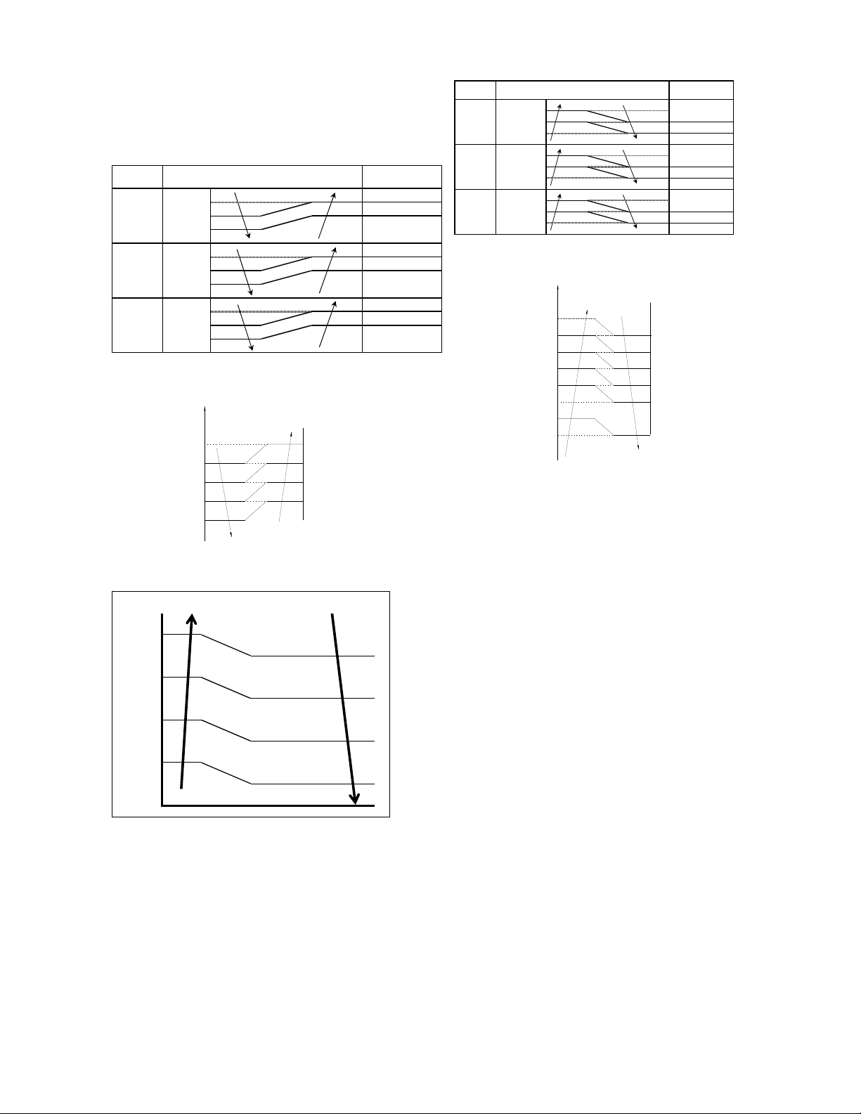
(
)
)
(
)
)
(
)
)
In cooling mode, indoor fan runs all the time
and the speed can be selected as high,
medium, low and auto.
The indoor fan is controlled as below:
Setting fan
speed
H
M
L
T1-Td ℃(°F)
4.5(40.1)
3.0(37.4)
1.5(34.7)
4.5(40.1)
3.0(37.4)
1.5(34.7)
4.5(40.1)
3.0(37.4)
1.5(34.7)
Actual fan speed
A H(=H)
B
C
D M(M=M)
E
F
G L(L=L)
H
I
H+(H+=H+G)
H-(H-=H-G)
M+(M+=M+Z)
M-(M-=M-Z)
L+(L+=L+D)
L-(L-=L-D)
Auto fan in cooling mode acts as follow:
T1-Td
6.0¡ãC(42.8¡ãF)
5.0¡ãC(41.0¡ãF)
4.0¡ãC(39.2¡ãF)
2.5¡ãC(36.5¡ãF)
1.0¡ãC(33.8¡ ãF)
a
b
c
d
e
H
(H-L)*0.75+L
(H-L)*0.5+L
(H-L)*0.25+L
L
14.4.3 Heating Mode
14.4.3.1 Outdoor fan running rules
T4
21℃(69.8°F)
19℃(66.2°F)
18℃(64.4°F)
16℃(60.8°F)
15℃(59°F)
13℃(55.4°F)
12℃(53.6°F)
10℃(50°F)
E DC_FAN_SSLOW_SPD_ADD
D DC_FAN_SLOW_SPD_ADD
C DC_FAN_MIN_SPD_ADD
B DC_FAN_MID_SPD_ADD
A DC_FAN_HI_SPD_ADD
14.4.3.2 Indoor fan running rules
When the compressor is on, the indoor fan can
be set to high/med/low/auto. And the anti-cold
wind function has the priority.
The indoor fan is controlled as below:
Setting fan
speed
H
M
L
T1-Td+1.5 ℃(34.7°F)
-1.5(29.3°F)
26.6°F
-3.0
-4.5(23.9°F
-1.5(29.3°F)
26.6°F
-3.0
-4.5(23.9°F
-1.5(29.3°F)
-3.0
26.6°F
-4.5(23.9°F
Actual fan speed
H-(H-=H-G)
H(=H)
H+(H+=H+G)
M-(M-=M-Z)
M(M=M)
M+(M+=M+Z)
L-(L-=L-D)
L(L=L)
L+(L+=L+D)
Auto fan action in heating mode:
1-Td+1.5¡ãC(34.7¡ãF)
0.0¡ãC(32¡ãF)
-1¡ãC(30.2¡ãF)
-2¡ãC(28.4¡ãF)
-3¡ãC(26.6¡ãF)
L
(H+-L)*0.2+L
(H+-L)*0.4+L
(H+-L)*0.6+L
-4¡ãC(24.8¡ãF)
-5¡ãC(23.0¡ãF)
-6¡ãC(21.2¡ãF)
-6.5¡ãC(20.3¡ãF)
(H+-L)*0.8+L
H+
14.4.3.3 Defrosting mode
If any one of the following items is satisfied, AC
will enter the defrosting mode.
After the compressor starts up and keeps
running, mark the minimum value of T3 from
the 10th minutes to 15th minutes as T30.
1)If the compressor cumulate running time is up
to 29 minutes and T3< TCDI1, T3 +
T30SUBT3ONE≦T30.
2)If the compressor cumulate running time is up
to 35 minutes and T3< TCDI2, T3 +
T30SUBT3TWO≦T30.
3)If the compressor cumulate running time is up
to 29 minutes and T3< TCDI3 for 3 minutes.
4)If the compressor cumulate running time is up
to 120 minutes and T3<-15℃(5°F).
Condition of ending defrosting:
If any one of the following items is satisfied, the
defrosting will finish and the machine will turn to
normal heating mode.
----T3 rises to be higher than TCDE1.
----T3 keeps to be higher than TCDE2 for 80
seconds.
----The machine has run for 10 minutes in
defrosting mode.
Defrosting action:
77
Page 81
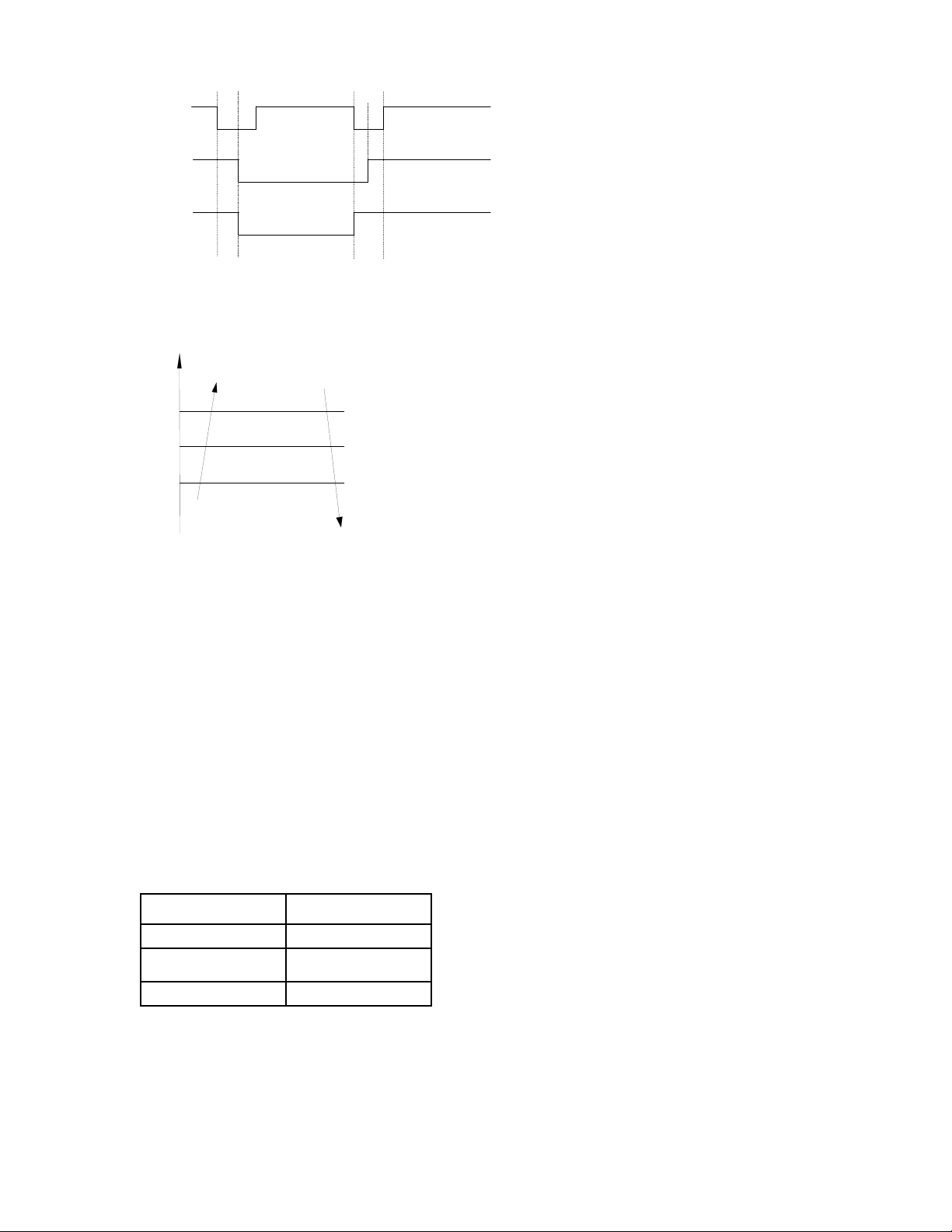
Compressor
4-Way valve
Outdoor fan
no longer than 10min
10S
X1
X2
10S
14.4.3.5 Evaporator coil temperature
protection
T2
TEstop
TEdown
TEH2
Off
Decrease
Hold
Resume
Off: Compressor stops.
Decrease: Decrease the running frequency to
the lower level.
Hold: Keep the current frequency.
Resume: No limitation for frequency.
14.4.4 Auto-mode
This mode can be chosen with remote
controller and the setting temperature can be
changed between 17~30℃(62.6~86°F).
In auto mode, the machine will choose cooling,
heating or fan-only mode according to ΔT (ΔT
=T1-Ts).
ΔT=T1-Ts Running mode
ΔT≥1℃(33.8°F) Cooling
-1℃ (30.2°F)<ΔT<1 ℃
(33.8°F)
ΔT≤-1℃(30.2°F) Heating
Fan-only
Indoor fan will run at auto fan of the relevant
mode.
The louver operates same as in relevant mode.
If the machine switches mode between heating
and cooling, the compressor will keep stopping
for 15 minutes and then choose mode
according to T1-Ts.
If the setting temperature is modified, the
machine will choose running function again.
14.4.5 Drying mode
Drying mode works the same as cooling mode
in low speed.
All protections are active and the same as that
in cooling mode.
14.4.6 Timer function
14.4.6.1 Timing range is 24 hours.
14.4.6.2 Timer on. The machine will turn on
automatically when reaching the setting time.
14.4.6.3 Timer off. The machine will turn off
automatically when reaching the setting time.
14.4.6.4 Timer on/off. The machine will turn on
automatically when reaching the setting “on”
time, and then turn off automatically when
reaching the setting “off” time.
14.4.6.5 Timer off/on. The machine will turn off
automatically when reaching the setting “off”
time, and then turn on automatically when
reaching the setting “on” time.
14.4.6.6 The timer function will not change the
AC current operation mode. Suppose AC is off
now, it will not start up firstly after setting the
“timer off” function. And when reaching the
setting time, the timer LED will be off and the
AC running mode has not been changed.
14.4.6.7 The setting time is relative time.
14.4.7 Sleep function mode
14.4.7.1 The sleep function is available in
cooling, heating or auto mode.
14.4.7.2. Operation process in sleep mode is as
follow:
When cooling, the setting temperature rises 1℃
(33.8°F) (be lower than 30℃(86°F)) every one
hour, 2 hours later the setting temperature
stops rising and the indoor fan is fixed at low
speed.
When heating, the setting temperature
decreases 1℃(33.8°F) (be higher than 17℃
(62.6°F)) every one hour, 2 hours later the
78
Page 82

setting temperature stops rising and indoor fan
is fixed at low speed. (Anti-cold wind function
has the priority).
14.4.7.3 Operation time in sleep mode is 7
hours. After 7 hours the AC quits this mode and
turns off
14.4.7.4 Timer setting is available.
14.4.8 Auto-Restart function
The indoor unit is equipped with auto-restart
function, which is carried out through an
auto-restart module. In case of a sudden power
failure, the module memorizes the setting
conditions before the power failure. The unit will
resume the previous operation setting (not
including sleep function) automatically after 3
minutes when power returns.
14.4.9 Follow me
1) If the indoor PCB receives the signal which
results from pressing the FOLLOW ME button
on remote controller or wired remote controller,
the buzzer will emit a sound and this indicates
the follow me function is initiated. But when the
indoor PCB receives signal which sent from
remote controller every 3 minutes, the buzzer
will not respond. When the unit is running with
follow me function, the PCB will control the unit
according to the temperature from follow me
signal, and the temperature collection function
of room temperature sensor will be shielded.
2) When the follow me function is available,
the PCB will control the unit according to the
room temperature from the remote controller
and the setting temperature.
3) The PCB will take action to the mode
change information from remote controller
signal, but it will not affected by the setting
temperature.
4) When the unit is running with follow me
function, if the PCB doesn’t receive any signal
from remote controller for 7 minutes or pressing
FOLLOW ME button again, the follow me
function will be turned off automatically, and the
temperature will control the unit according to
the room temperature detected from its own
room temperature sensor and setting
temperature.
14.4.10 8℃ Heating(optional)
In heating operation, the preset temperature of
the air conditioner can be as lower as 8 ℃
(46.4°F), which keeps the room temperature
steady at 8℃(46.4°F) and prevents household
things freezing when the house is unoccupied
for a long time in severe cold weather.
1.3.11 Drain pump control
Adopt the water-level switch to control the
action of drain pump.
Main action under different condition :( every 5
seconds the system will check the water level
one time)
1. When the A/C operates with cooling
(including auto cooling), dehumidifying, and
forced cooling mode, the pump will start
running immediately and continuously, till stop
cooling.
2. Once the water level increase and up to the
control point, LED will alarm and the drain
pump open and continue checking the water
level. If the water level fall down and LED
disalarmed (drain pump delay close 1 minute)
and operate with the last mode. Otherwise the
entire system stop operating (including the
pump) and LED remain alarming after 3
minutes,
79
Page 83
Point check function
Press the LED DISPLAY or LED or MUTE button of the remote controller three times, and then press
the AIR DIRECTION or SWING button three times in ten seconds, the buzzer will keep ring for two
seconds. The air conditioner will enter into the information enquiry status. You can press the LED
DISPLAY or AIR DIRECTION button to check the next or front item’s information.
When the AC enter the “information enquiry” status, it will display the code name
details are as follows.
Enquiry information Displaying code Meaning
T1 T1 T1 temp.
T2 T2 T2 temp.
T3 T3 T3 temp.
T4 T4 T4 temp.
T2B Tb T2B temp.
TP TP TP temp.
TH TH TH temp.
Targeted Frequency FT Targeted Frequency
Actual Frequency Fr Actual Frequency
Indoor fan speed IF Indoor fan speed
Outdoor fan speed OF Outdoor fan speed
EXV opening angle LA EXV opening angle
Compressor continuous running time CT Compressor continuous
Causes of compressor stop. ST Causes of compressor
Reserve A0
Reserve A1
Reserve 0
Reserve 1
Reserve 2
Reserve 3
Reserve 4
Reserve 5
Reserve 6
Reserve L
Reserve A
Reserve U
Reserve T
running time
stop.
in 2 seconds, the
80
Page 84
When the AC enter into the information enquiry status, it will display the code value in the next 25s
details are as follows.
Enquiry
information
T1,T2,T3,T4,
T2B,TP,TH,
Targeted
Frequency,
Actual
Frequency
Indoor fan
speed
/Outdoor fan
speed
EXV opening
angle
Compressor
continuous
running time
Causes of
compressor
stop.
Reserve 0-FF
Display value Meaning Remark
-1F,-1E,-1d,-1c,-
1b,-1A
-19—99 -19—99
A0,A1,…A9 100,101,…109
b0,b1,…b9 110, 111 , …11 9
c0,c1,…c9 120,121,…129
d0,d1,…d9 130,131,…139
E0,E1,…E9 140,141,…149
F0,F1,…F9 150,151,…159
0 OFF
1,2,3,4 Low speed, Medium
14-FF Actual fan
0-FF Actual EXV opening
0-FF 0-255 minutes If the actual value exceeds the
0-99 For the detailed
-25,-24,-23,-22,-21,-20 1. All the displaying temperature is actual
value.
2. All the temperature is °C no matter
what kind of remote controller is used.
3. T1,T2,T3,T4,T2B display range:-25~70,
TP display range:-20~130.
4. Frequency display range: 0~159HZ.
5. If the actual value exceeds the range, it
will display the maximum value or minimum
value.
For some big capacity motors.
speed, High speed,
Turbo
For some small capacity motors,
speed=Display value
turns to decimal
value and then
multiply 10. The unit
is RPM.
value=Display value
turns to decimal
value and then
multiply 2.
meaning, please
consult with engineer
display value is from 14-FF(hexadecimal),
the corresponding fan speed range is from
200-2550RPM.
range, it will display the maximum
value or minimum value.
Decimal display
, the
81
Page 85
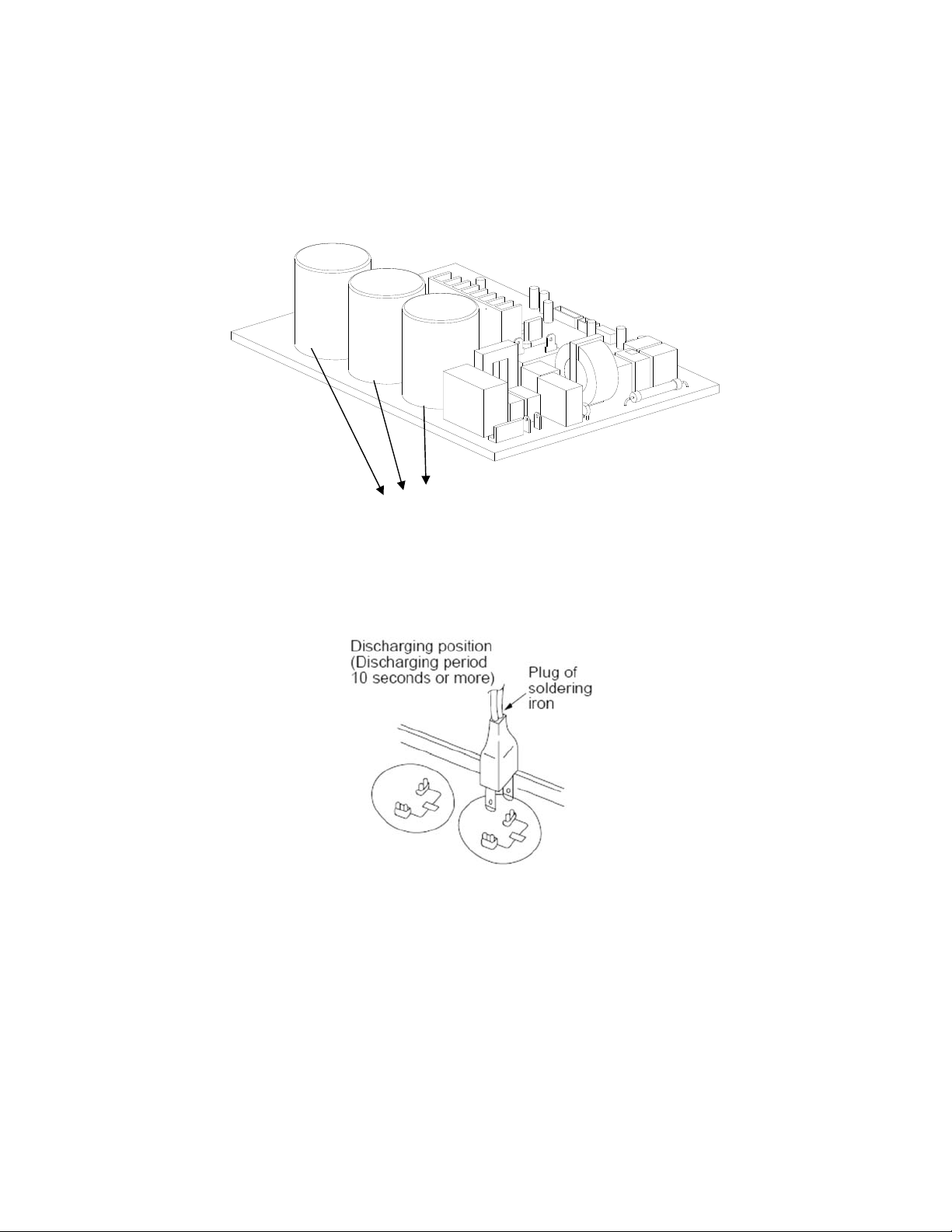
16. Troubleshooting
Safety
Electricity power is still kept in capacitors even the power supply is shut off. Do not forget to discharge the electricity
power in capacitor.
Electrolytic Capacitors
(HIGH VOLTAGE! CAUTION!)
For other models, please connect discharge resistance (approx.100Ω 40W) or soldering iron (plug) between +, -
terminals of the electrolytic capacitor on the contrary side of the outdoor PCB.
Note: The picture above is only for reference. The plug of your side may be different.
82
Page 86
16.1 Indoor Unit Error Display
Operation
lamp
☆ 1 time
☆ 2 times
☆ 4 times
☆ 5 times
☆ 6 times
☆ 7 times
☆ 8 times
☆ 1 time
☆ 2 times O F1 Outdoor ambient temperature sensor (T4 ) malfunction
☆ 3 times
☆ 4 times
☆ 5 times
☆ 6 times
Timer lamp Display LED STATUS
X
X
X
X
X
X
X
O F0 Current overload protection
O
F2 Condenser coil temperature sensor (T3) malfunction
O
O
F4 Outdoor unit EEPROM parameter error
O
F5 Outdoor fan speed has been out of control
E0 Indoor unit EEPROM parameter error
E1
E3 Indoor fan speed has been out of control
E4 Indoor room temperature sensor (T1 ) malfunction
E5 Evaporator coil temperature sensor (T2) malfunction
EC Refrigerant leakage detection
EE Water-level alarm malfunction
F3
Communication malfunction between indoor and
outdoor units
Compressor discharge temperature sensor (T5)
malfunction
☆ 7 times
☆ 8 times
☆ 9 times
☆ 10 times
☆ 1 times ☆
☆ 2 times ☆
☆ 3 times ☆
☆ 4 times ☆
☆ 5 times ☆
☆ 6 times ☆
☆ 7 times ☆
☆ 8 times ☆
O F6
O F7
O F8 Cassette optional lift panel malfunction
O F9 Cassette optional lift panel not closed
P0 Inverter module (IPM) malfunction
P1 Over-voltage or under-voltage protection
P2 Compressor top high temperature protection (OLP)
P3 Low ambient temperature cut off in heating
P4 Compressor drive malfunction
P5 Indoor units mode conflict
P6 Low pressure protection
P7 Outdoor IPM temperature sensor error
O(light) X(off) ☆(flash)
Indoor coil outlet pipe sensor(Located on outdoor unit
low pressure valve)
Communication malfunction between Cassette optional
lift panel and the unit
83
Page 87
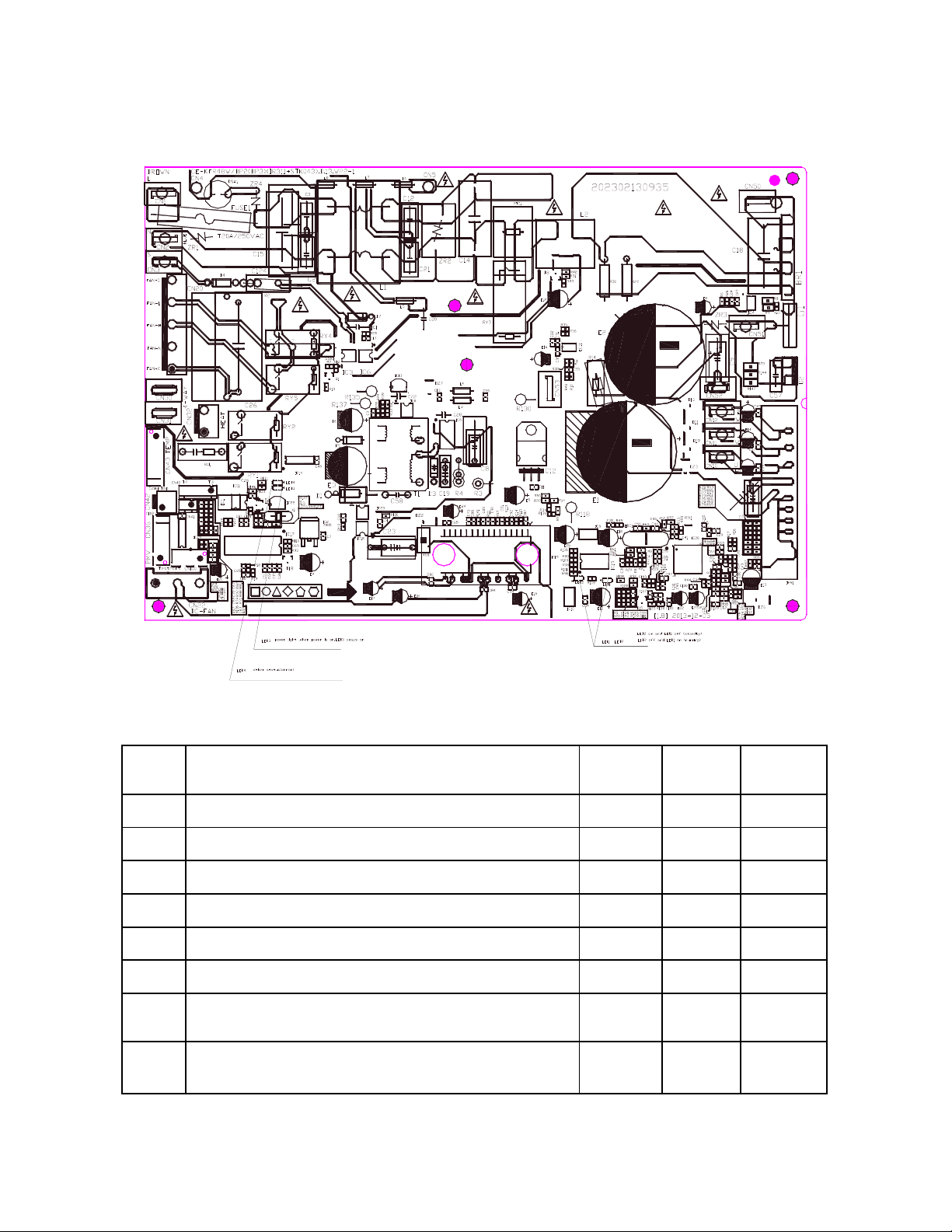
16.2 Outdoor unit error display
For 9K-24K outdoor unit:
No. Problems
1 standby for normal O X
2 Operation normally X O
3 Compressor drive board EEPROM error O
4 IPM malfunction or IGBT over-strong current protection
5 Over voltage or too low voltage protection O O P1
6 Inverter compressor drive error X
7 Inverter compressor drive error
Communication malfunction between main control board
8
and driver board
84
LED2
(Green)
☆
☆
☆ ☆
LED1
(Red)
☆
X P0
☆
O P4
IU display
E5
P4
P4
Page 88
For 36K-48K Outdoor Unit
No Problems Error Code
1 Communication malfunction between indoor and outdoor units E1
2 Current overload protection F0
3 Outdoor ambient temperature sensor (T4 ) malfunction F1
4 Condenser coil temperature sensor (T3) malfunction F2
5 Compressor discharge temperature sensor (T5) malfunction F3
6 Outdoor unit EEPROM parameter error F4
7 Outdoor fan speed has been out of control F5
8
Inverter module (IPM) malfunction
9 Over-voltage or under-voltage protection P1
10
Compressor top high temperature protection (OLP) P2
11
Low ambient temperature cut off in heating P3
12 Compressor drive malfunction P4
13 High temperature protection of indoor coil in heating J0
14 Outdoor temperature protection of outdoor coil in cooling J1
15 Temperature protection of compressor discharge J2
16 PFC module protection J3
P0
17 Communication malfunction between control board and IPM board J4
18 High pressure protection J5
19 Low pressure protection J6
20
Outdoor IPM module temperature sensor malfunction
21 AC voltage protection J8
P7
85
Page 89
Outdoor check function
N Display Remark
00 Normal display
01 Indoor unit capacity demand code
02 Amendatory capacity demand code
The frequency after the capacity requirement
03
transfer
04 The frequency after the frequency limit
05 The frequency of sending to 341 chip
Indoor unit evaporator outlet temp.(heating T2
06
cooling T2B)
07 Condenser pipe temp.(T3) If the temp. is lower than -9 degree, the digital display tube
08 Outdoor ambient temp.(T4)
09 Compressor discharge temp.(T5)
10 AD value of current
11 AD value of voltage
12 Indoor unit running mode code Off:0, Fan only 1,Cooling:2, Heating:3
13 Outdoor unit running mode code Off:0, Fan only 1,Cooling:2, Heating:3, Forced cooling:4
14 EXV open angle
Display running frequency, running state or malfunction
code
Actual data*HP*10
If capacity demand code is higher than 99, the digital display
tube will show single digit and tens digit. (For example, the
digital display tube show “5.0”,it means the capacity demand
is 15. the digital display tube show “60”,it means the
capacity demand is 6.0)
If the temp. is lower than 0 degree, the digital display tube
,
will show “0”.If the temp. is higher than 70 degree, the digital
display tube will show “70”.
will show “-9”.If the temp. is higher than 70 degree, the
digital display tube will show “70”. If the indoor unit is not
connected, the digital display tube will show: “――”
The display value is between 13~129 degree. If the temp. is
lower than 13 degree, the digital display tube will show
“13”.If the temp. is higher than 99 degree, the digital display
tube will show single digit and tens digit. (For example, the
digital display tube show “0.5”,it means the compressor
discharge temp. is 105 degree. the digital display tube show
“1.6”,it means the compressor discharge temp. is 116
degree)
The display value is hex number.
Actual data/4.
If the value is higher than 99, the digital display tube will
show single digit and tens digit.
For example, the digital display tube show “2.0”,it means the
EXV open angle is 120×4=480p.)
86
Page 90
Frequency limit caused by
Bit7
IGBT radiator
Frequency limit caused by
Bit6
PFC
Bit5 Frequency limit caused by T4.
15 Frequency limit symbol
16 DC fan motor speed
17 IGBT radiator temp.
Indoor unit number The indoor unit can communicate with outdoor unit well.
18
19 Evaporator pipe temp. T2 of 1# indoor unit
20 Evaporator pipe temp. T2 of 2# indoor unit
21 Evaporator pipe temp. T2 of 3# indoor unit
22 1# Indoor unit capacity demand code
23 2# Indoor unit capacity demand code
24 3# Indoor unit capacity demand code
25 Room temp. T1 of 1# indoor unit
26 Room temp. T1 of 2# indoor unit
27 Average room temp. T1
28 Reason of stop
29 Evaporator pipe temp. T2B of 1# indoor unit
30 Evaporator pipe temp. T2B of 2# indoor unit
Bit4 Frequency limit caused by T2.
Bit3 Frequency limit caused by T3.
Bit2 Frequency limit caused by T5.
Frequency limit caused by
Bit1
current
Frequency limit caused by
Bit0
voltage
The display value is between 30~120 degree. If the temp. is
lower than 30 degree, the digital display tube will show
“30”.If the temp. is higher than 99 degree, the digital display
tube will show single digit and tens digit. (For example, the
digital display tube show “0.5”,it means the IGBT radiator
temp. is 105 degree. the digital display tube show “1.6”,it
means the IGBT radiator temp. is 116 degree)
General:1, Twins:2
If the temp. is lower than 0 degree, the digital display tube
will show “0”.If the temp. is higher than 70 degree, the digital
display tube will show “70”. If the indoor unit is not
connected, the digital display tube will show: “――”
Actual data*HP*10
If capacity demand code is higher than 99, the digital display
tube will show single digit and tens digit. (For example, the
digital display tube show “5.0”,it means the capacity demand
is 15. the digital display tube show “60”,it means the
capacity demand is 6.0). If the indoor unit is not connected,
the digital display tube will show: “――”
If the temp. is lower than 0 degree, the digital display tube
will show “0”.If the temp. is higher than 70 degree, the digital
display tube will show “70”. If the indoor unit is not
connected, the digital display tube will show: “――”
If the temp. is lower than 0 degree, the digital display tube
will show “0”.If the temp. is higher than 70 degree, the digital
display tube will show “70”. If the indoor unit is not
connected, the digital display tube will show: “――”
The display value is
hex number. For
example, the digital
display tube show
2A, then Bit5=1,
Bit3=1, Bit1=1.
It means frequency
limit caused by T4,
T3 and current.
87
Page 91
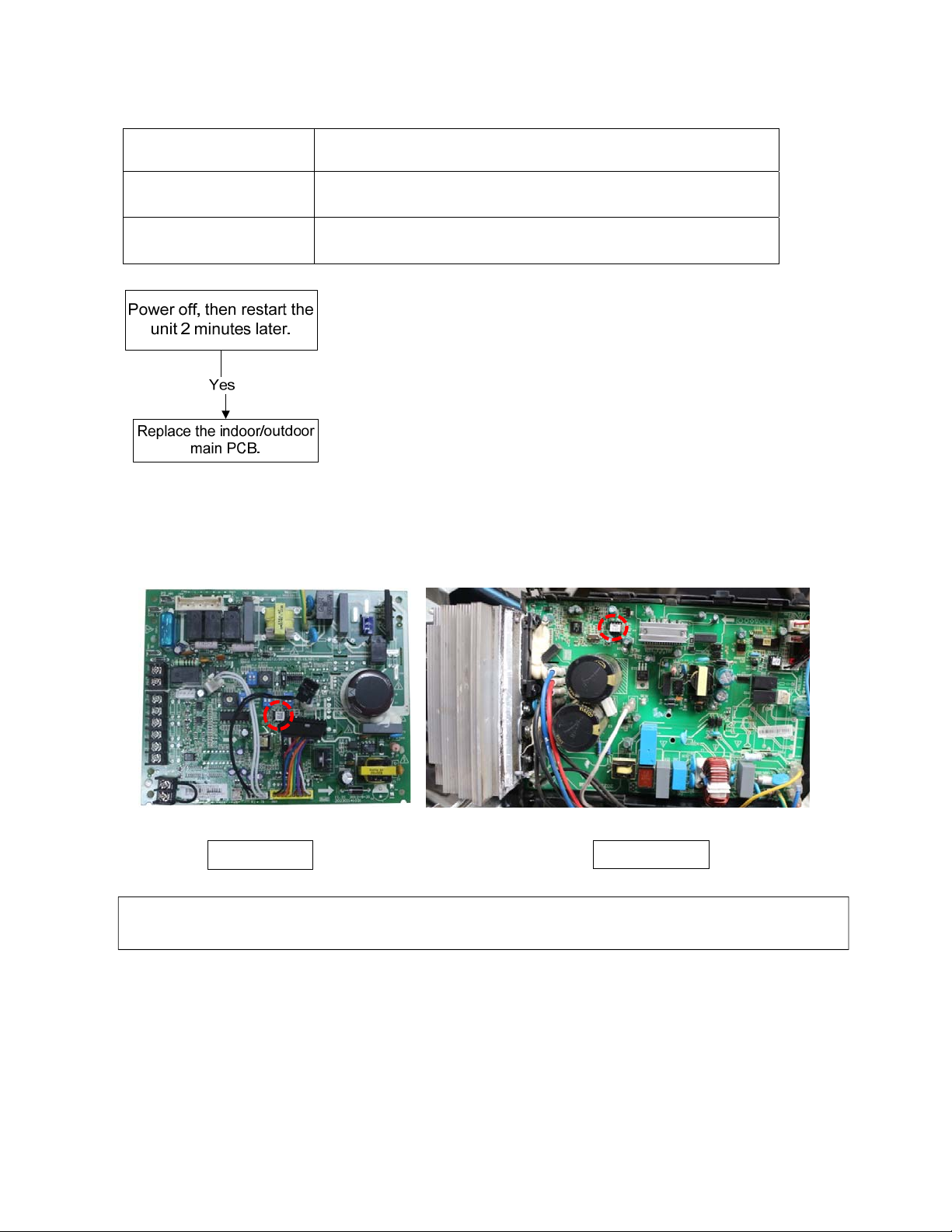
16.3 Diagnosis and Solution
your
16.3.1 EEPROM error diagnosis and solution (E0/F4)
Error Code
E0/F4
Malfunction decision
conditions
Supposed causes ● Installation mistake
Indoor or outdoor PCB main chip does not receive feedback
from EEPROM chip.
● PCB faulty
Trouble shooting:
EEPROM:
An electrically erasable programmable read-only memory whose contents can be erased
and reprogrammed using a pulsed voltage.
Indoor PCB Outdoor PCB
Note: The two photos above are only for reference, it’s may be not same totally with the ones on
side.
88
Page 92
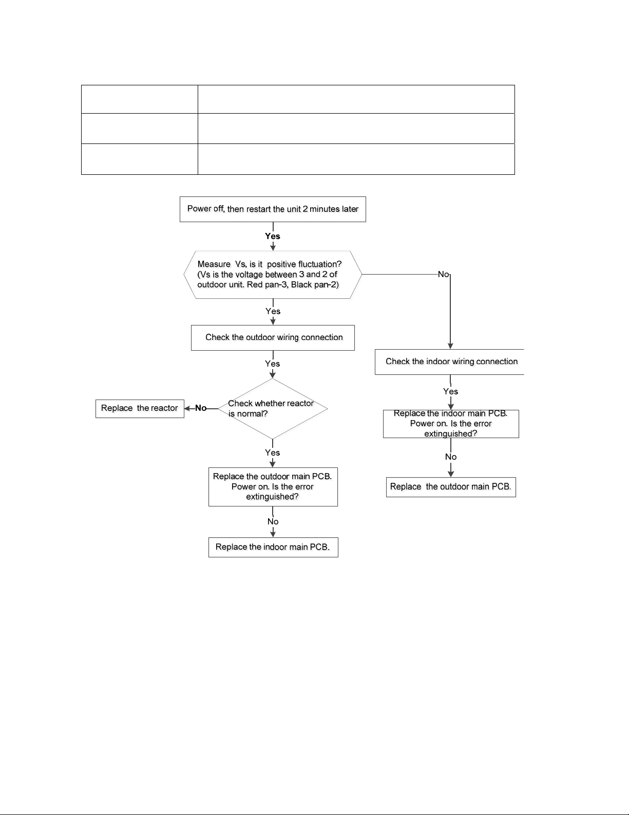
16.3.2 Communication malfunction between indoor and outdoor units diagnosis and solution
(E1)
Error Code
E1
Malfunction decision
conditions
Supposed causes ● Wiring mistake
Indoor unit does not receive the feedback from outdoor unit during
110 seconds and this condition happens four times continuously.
● Indoor or outdoor PCB faulty
Trouble shooting:
89
Page 93
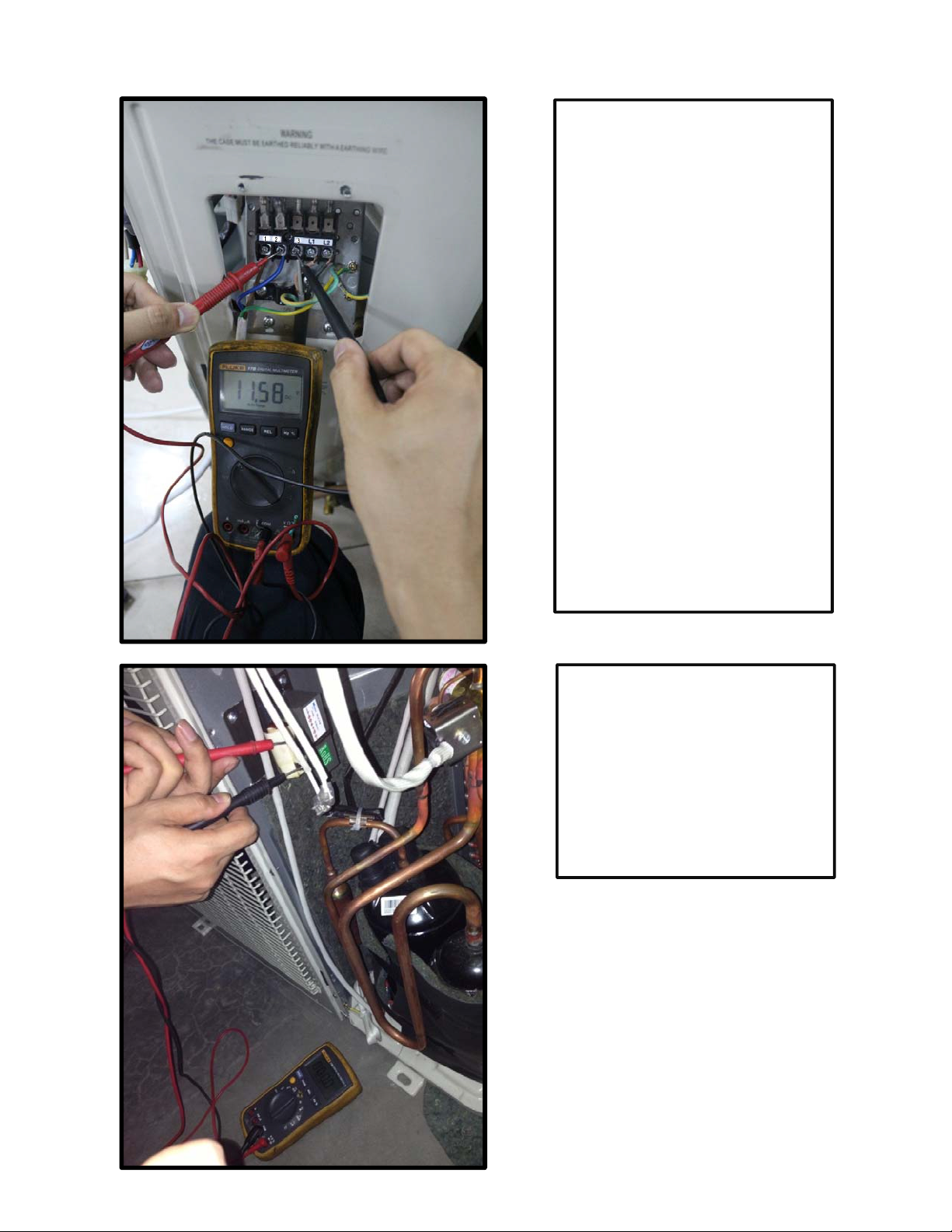
Remark:
Use a multimeter to test the DC
voltage between 2 port and 3 port of
outdoor unit. The red pin of
multimeter connects with 2 port while
the black pin is for 3 port.
When AC is normal running, the
voltage will move alternately between
-50V to 50V.
If the outdoor unit has malfunction,
the voltage will move alternately with
positive value.
While if the indoor unit has
malfunction, the voltage will be a
certain value.
Remark,
The old label is L1,L2,S, L1,L2
The new label is 1, 2, 3, L1,L2
Remark:
Use a multimeter to test the
resistance of the reactor which does
not connect with capacitor.
The normal value should be around
zero ohm. Otherwise, the reactor
must have malfunction and need to
be replaced.
90
Page 94
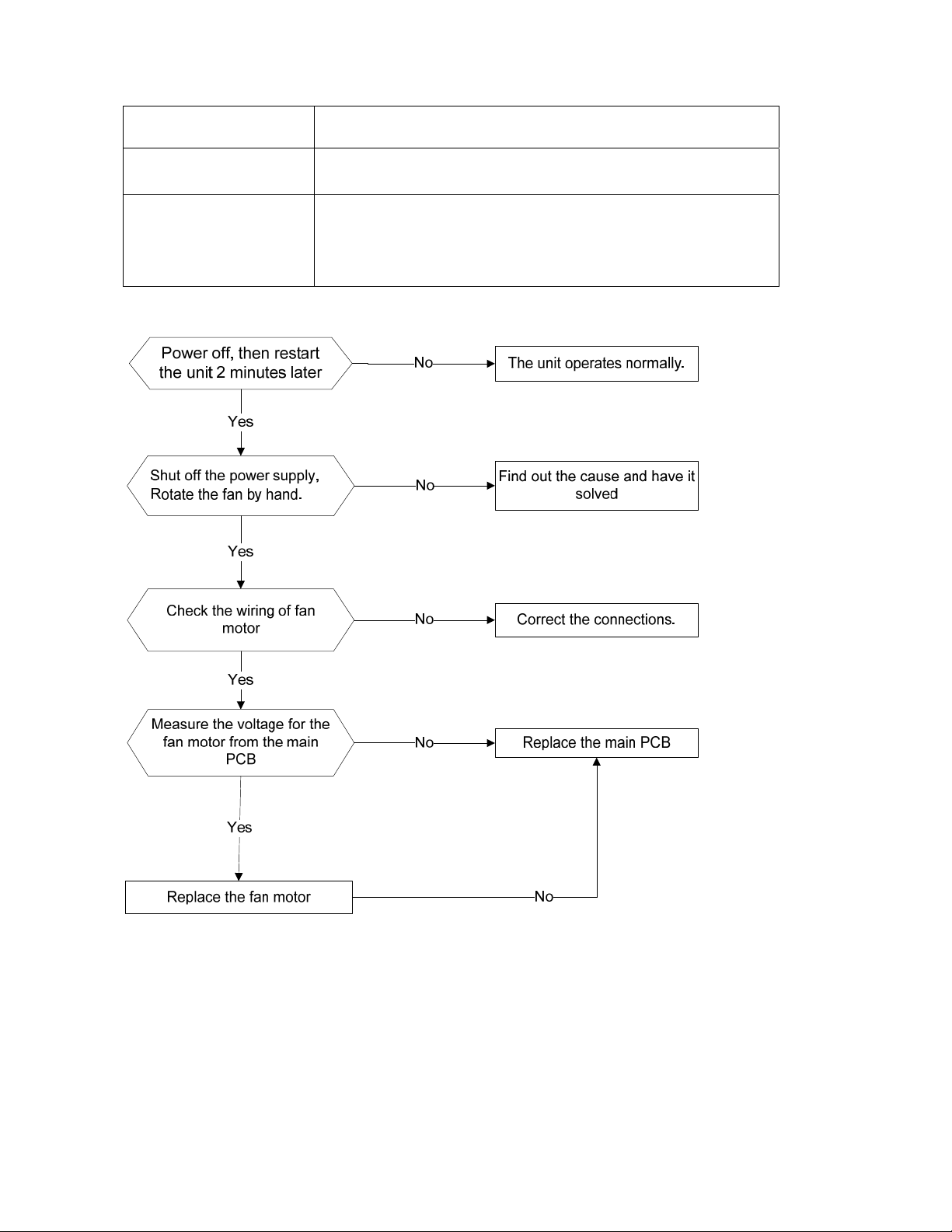
16.3.3 Fan speed has been out of control diagnosis and solution (E3)
Error Code
Malfunction decision
conditions
Supposed causes
Trouble shooting:
E3
When indoor fan speed keeps too low (300RPM) for certain time,
the unit will stop and the LED will display the failure.
● Wiring mistake
● Fan ass’y faulty
● Fan motor faulty
● PCB faulty
91
Page 95
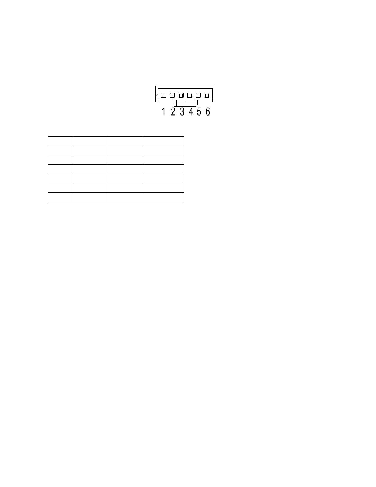
Index 1:
1
. Indoo
Power
conn
roblems and need to be replaced.
p
DC
r DC fan motor(control chip is inside fan moto
r)
on and when the unit is in standby, measure the voltage of pin1-pin3, pin4-pin3 in fan moto
ector. If the value of the voltage is not in the range showing in below table, the PCB must h
motor voltage input and output
NO. Color Signal Voltage
1 Red Vs/Vm 200~380V
2 --- --- ---
3 Black GND 0V
4 White Vcc 13.5~16.5V
5 Yellow Vsp 0~6.5V
6 Blue FG 13.5~16.5V
r
ave
92
Page 96
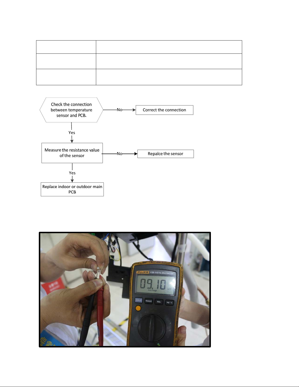
16.3.4 Open circuit or short circuit of temperature sensor diagnosis and solution
(E4/E5/F1/F2/F3)
Error Code
E4/E5/F1/F2/F3
Malfunction decision
conditions
If the sampling voltage is lower than 0.06V or higher than 4.94V,
the LED will display the failure.
Supposed causes ● Wiring mistake
● Sensor faulty
Trouble shooting:
93
Page 97
16.3.5 Refrigerant Leakage Detection diagnosis and solution (EC)
Error Code
EC
Malfunction decision
conditions
Supposed causes ● T2 sensor faulty
Define the evaporator coil temp.T2 of the compressor just starts
running as Tcool.
In the beginning 5 minutes after the compressor starts up, if T2
<Tcool-2℃ does not keep continuous 4 seconds and this
situation happens 3 times, the display area will show “EC” and
AC will turn off.
● Indoor PCB faulty
● System problems, such as leakage or blocking.
Trouble shooting:
Power off, then restart the
unit 2 minutes later.
Yes
Check cool air blowing out
from indoor air outlet
No
Yes
Check if T2 sensor
Yes
Check leakage of system
No
check blockIng of system and
clear the blocking
Yes
Replace indoor PCB.
Repair the leakage and
recharge the refrigerant.
94
Page 98
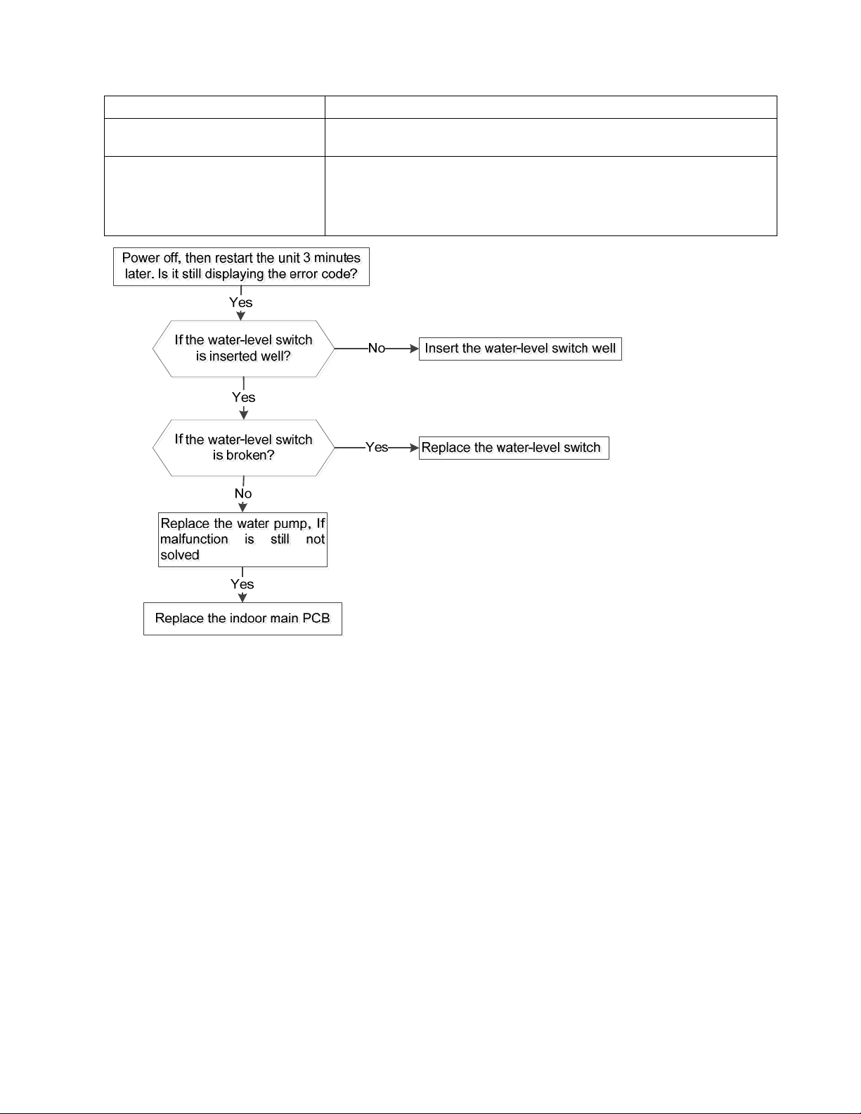
16.3.6
Error Code
Water-level alarm malfunction diagnosis and solution
Malfunction decision
conditions
Supposed causes
EE
If the sampling voltage is not 5V, the LED will display the
failure.
● Wiring mistak
●
Water-level switch faulty
e
● Water pump faulty
● Indoor PCB fau
lty
95
Page 99
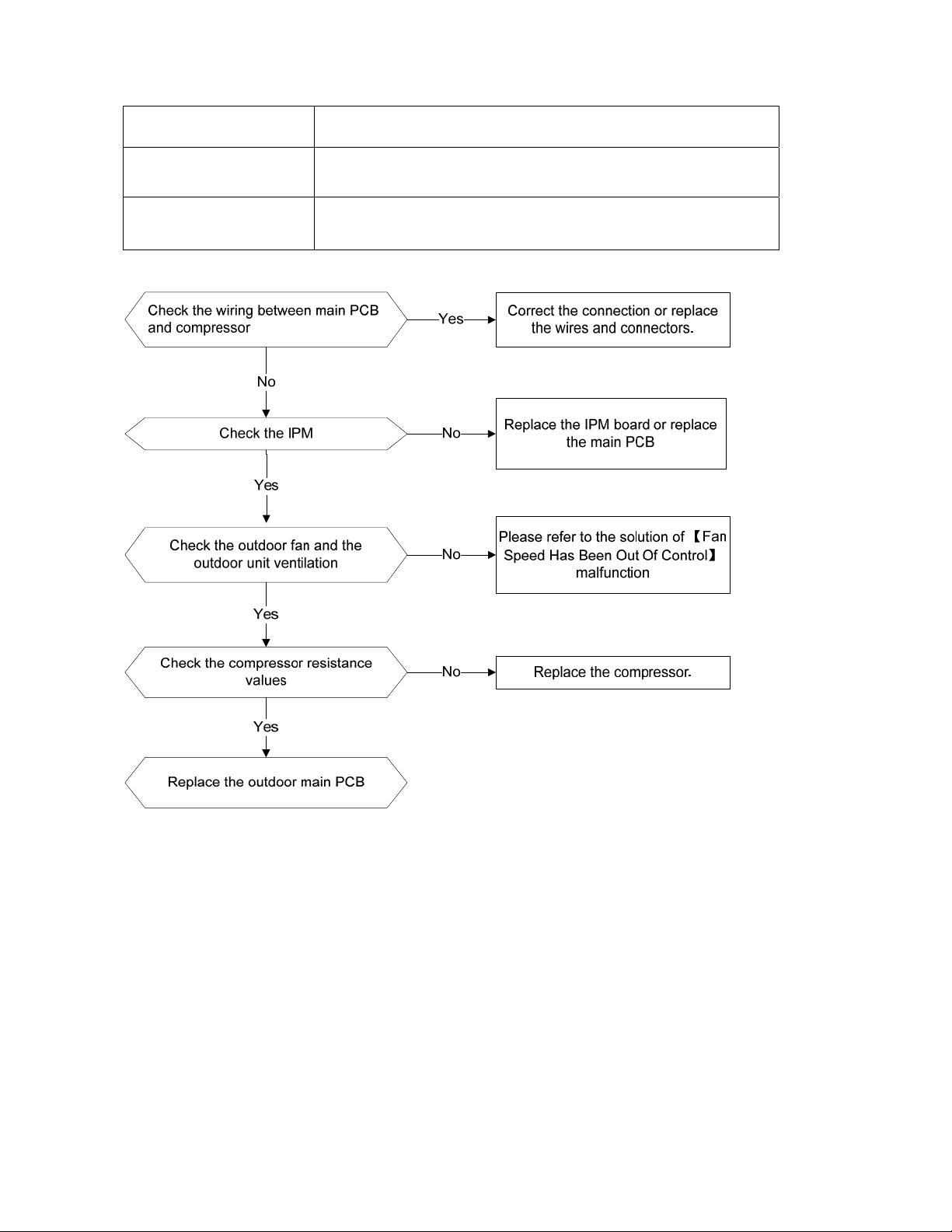
16.3.7 IPM malfunction or IGBT over-strong current protection diagnosis and solution (P0)
Error Code
Malfunction decision
conditions
Supposed causes
Trouble shooting:
P0
When the voltage signal that IPM send to compressor drive chip
is abnormal, the display LED will show “P0” and AC will turn off.
Wiring mistake; IPM malfunction; Outdoor fan ass’y faulty
Compressor malfunction; Outdoor PCB faulty
96
Page 100
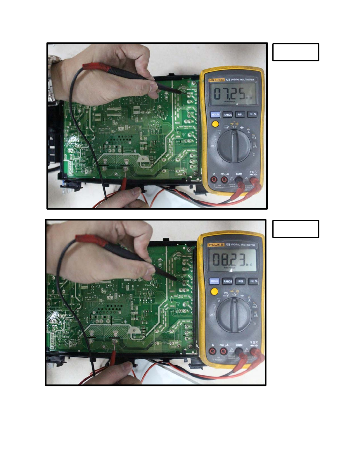
P-U
P-V
97
 Loading...