

Pioneer TX-530-L Service manual
()
rrloNEEFt'
STEREO
TUNER
TXISSOL
o
This
service
o
ce manuel
o
Este
manual
MODEL
Type
HE
HB
CONTENTS
1.
SPECIFICATIONS
FRONT
2.
PARTS
3.
4.
BLOCK
5.
CIRCUIT
DIAL
6.
7.
P.C.
BOARDS
CORD
manual is
d'instruction
de
servicio
TX-530L
PANEL
LOCATION
DIAGRAM
DESCRIPTIONS.
COMES
22OV and
22OV and24OV
FACILITIES
STRINGING
CONNECTION
applicable
to the
se refdre
trata
del
IN
TWO
Voltage
24OY
DIAGRAM
HE,
HB
au mode
m6todo
de r6glage,
de
VERSIONS
types.
en frangais.
ajuste escrito
DISTINGUISHED
2
3
4
5
5
6
7
8.
9.
10.
11.
12.
en
espafrot.
REMARKS
Europe
model
U.K. model
SCHEMATIC
ELECTRICAL
EXPLODEDVIEW...
PACKING
ADJUSTMENTS
DIAGRAM
PARTS
..
nEclnce
AJUSTE
ORDER
ARP
AS FOLLOWS:
Remarks
LIST.
.
NO.
-086-O
9
11
13
14
15
17
19
CHANGE
When
transformer.
PICINEEFI
fJ'''
FE'ifIIF|
F|C
NTIF|
FE'NtlFl
lllcr;loNtc
ILICTFIC'NICa
OF LINE
switching
ELECTFICINIC
ILIC?!|CINIC!
(ErJFroPEt
VOLTAGE
trom
over
CCIFIFCIFIATICIN
AUaTFIALIA
22OY
CCIFIPCIFIATICIN
N.v' Luirh€gen-H.ven
P?Y.
to 24OV,
E}5
Oxfond D.ive. Moonechte,
LTo. 178. 1A4
change
4-1.
Meeu.o 1-chome,
g.
eo3o
anrweFp,
Elouncie.y Road,
the connection
rwesu.o-ku,
New Jens€v
Elelgium
Bnaes.de, vacconia
o7o74.
Tokyo 1s3,
31
of
L).s.A.
95.
the
a.u6r.6tr6
lead
J6p6n
YU O
wire for
1982
JAN.
the
Printed
power
in
lapan
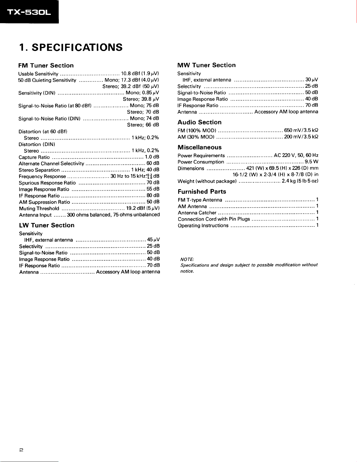
1.
SPECIFICATIONS
Tuner
FM
Usable Sensitivity
50 dB Ouieting Sensitivity
Sensitivity(DlN)
Signal-to-Noise
Signal-to-Noise
Distortion
Stereo........
Distortion
Stereo
CaptureRatio..........
Alternate Channel
Stereo Separation
Frequency Response
Spurious
lmage Response Ratio
Response Ratio ..........
lF
AM
Suppression
Muting
Antenna Input . . . . .. . 300
Section
.........
Ratio
Ratio
(at
dBf)
@
(DlN)
........
Selectivity
Response
Ratio
Threshold
(at
80 dBf)
(DlN)
............
Ratio .........
ohms balanced,
LW Tuner Section
Sensitivity
lHF, external antenna
selectivity
Signal-to-Noise
lmage Response
lF Response
Antenna
Ratio
Ratio
Ratio ..........
.........
...... 30
Accessory
10.8 dBf
Mono; 17.3
Stereo; 39.2
75 ohms unbalanced
dBf
dBf
Mono;0.85pV
Stereo; 39.8
Mono; 75 dB
..
Stereo;
Mono;74d8
Stereo;
l k{z:O.2o/o
....,..
....... 1 kHz,O.2o/o
......1.0d8
................ 60
1 kHz;
Hz to 15 kHz:!
...........
. . . . .. 55 dB
...... 50 dB
19.2 dBf
....... 50
......
looP
AM
(1.9
sV)
(4.0
prV)
(50
pV)
lV
70 dB
66 dB
dB
ztO
dB
dB
fr
70 dB
..
dB
80
(5
pV)
45pV
....
dB
... 25
40 dB
..70 dB
antenna
dB
MW Tuner Section
Sensitivity
lHF, external
selectivity
Signal-to-Noise
lmage Response
lF Response
Antenna
Audio
(100%
FM
(30%
AM
antenna
Ratio
Ratio
Ratio ..........
Section
MOD) .........
MOD) .........
Miscellaneous
Requirements
Power
Power Consumption
Dimensions
Weight
(without
Furnished
FMT-typeAntenna
AM Antenna
Antenna Catcher
Connection Cord
Operating
NOTE:
Specifications
notice.
package)
Parts
Pin Plugs
with
lnstructions
and design subject
....421
16-1/2
Accessory
........
(W)
x@.5(H)
(W)
x 2-3/4
possible
to
.... 30pV
... 25 dB
.. 70
antenna
(D)
(5
lb 5 oz)
without
dB
dB
Hz
W
mm
in
1
1
1
1
....... 50
...... 40 dB
loop
AM
mV/3.5 ka
650
200 mV/3.5 ka
AC 220 V, 50, 60
........ 9.5
x226{D)
(H)
x 8-718
. ..... 2.4 kg
...............1
........................
...................
..................
............
modification
<
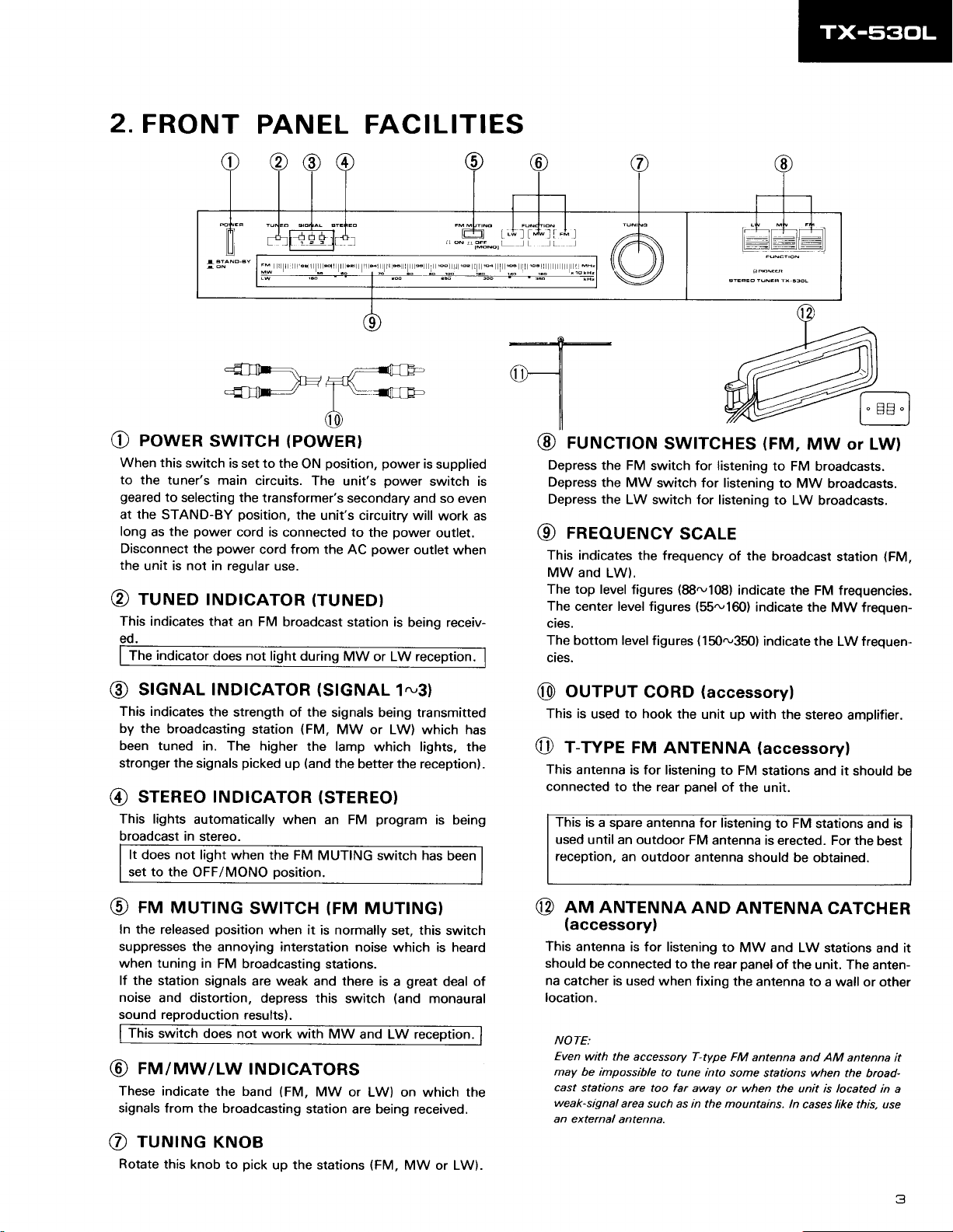
2.FRONT
PANEL FACILITIES
poweR
O
When this
to
geared
the
at
long
Disconnect
the
rurueo
@
This indicates
ed.
The
switch is
the tuner's main
to
selecting the
STAND-BY
power
the
as
the
unit is not in regular
indicator
r) e)
m
l3l;-*
(3) (4) (5) (6
ttt
ru^lEo
s'6+al 6rE+Eo
I r-=-f-T-] r
L
]L_::Jt
lffi#l
swtrcH
position.
cord is connected to
power
tNDlcAToR
that an FM
does not
(powER)
set to the
circuits.
transformer's
the
cord from the
use.
broadcast
light during
ON
The unit's
(TUNED)
]
9
position, power
secondary
unit's circuitry
the
power
AC
station
MW or LW reception.
is
oower switch is
and so even
will work as
power
outlet
is
being receiv-
tttl
FMMl,i,No
supplied
outlet.
when
FUN4noN
I
I
rurucnoN
@
Depress
Depress
Depress the
rneouENcY
@
This indicates
MW and
The top level
The
center level figures
cies.
The bottom level
cies.
@
the FM
the MW
LW switch
the frequency
LW).
figures
.I -t
l:trlrl rl
swtTcHES
switch for listening
switch for listening
for listening to
(FM,
scALE
of the
(88ru'108)
figures
indicate the
(55ru160)
(150-350)
indicate the
indicate
.L
MW or
to FM
broadcasts.
to
MW broadcasts.
LW broadcasts.
broadcast
station
FM frequencies.
MW frequen-
the LW frequen-
a;:-l
I o FlFi o I
t--l
LW)
(FM,
stcNAL tNDtcAToR
@
This indicates
by the
been tuned
stronger
sreneo rNDtcAToR
@
This lights
broadcast
It does not light
set to the
mu MUTTNG
@
In the released
suppresses the
when tuning in
lf the station
noise
and distortion,
sound reproduction
This
switch does not
rulnnw/Lw
@
These indicate
signals from the
rurutruc
@
Rotate
the
strength of the
broadcasting
in. The higher
the
automatically
in stereo.
OFF/MONO
picked
signals
when the FM
position
annoying interstation noise
FM broadcasting
signals
results).
the band
broadcasting
KNoB
this
knob to
pick
station
position.
swtrcH
when
are weak and there is
depress this
work with MW
rNDtcAToRs
up the stations
(stcNAL
signals being transmitted
(FM,
MW or LW) which has
the lamp
(and
up
the
1.,31
which lights, the
better the reception).
(srEREo)
when an FM
MUTING switch has
(FM
it is normally
stations.
(FM,
MW
station are being received.
program
MUTTNG)
set, this switch
which is heard
great
a
switch
(and
and LW reception.
or LW) on which the
(FM,
MW or LW).
is being
been
deal of
monaural
oureuT
@
This is
r-wpe
@
This
connected
This is
used
reception.
nrta ANTENNA
@
(accessory)
This antenna
should
na
catcher is used
location.
NO7-E:
Even
may be impossible
cast
weak-signal
an external
to
used
FM
antenna
stations are too far
is for listening
to the rear
a spare
until an outdoor
an outdoor
is for listening
be connected
with the
accessory T-type FM
area such as in
antenna.
coRD
hook the
(accessory)
unit up with the
ANTENNA
to FM
panel
of the
antenna for listening
FM
antenna is erected. For the
antenna should
AND ANTENNA
to
MW and LW
to the rear
when fixing
to tune into some
away
panel
the antenna to
antenna
or when the unit is located
mountains.
the
stereo
amplifier.
(accessoryl
stations and it should
unit.
to FM
stations and
best
be obtained.
cATcHER
stations and it
of the
unit. The anten-
a wall or other
and AM antenna it
stations when
ln
the broad-
cases like this, use
be
in a
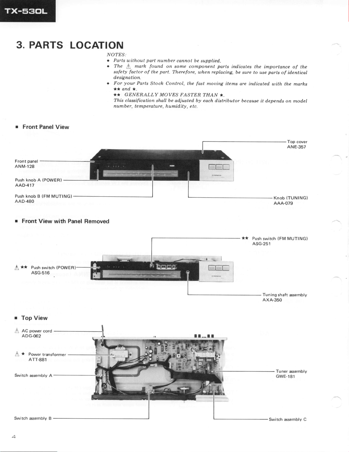
PARTS
3.
r
Front
panel
Front
ANM-128
Panel
LOCATION
View
NO?ES:
e
Parts
o
o
without
The
safety
designation.
For
**
*T
This classification
number,
marh
I
factor
your
Parts
and *.
GENESALLY
temperature, humidity, e
part
number
found
of the
Stoch Control, the
shall
cannot be
on
some
part.
Therefore, when replacing,
MOVES
be
adjusted by each
component
fast
FAS'I:ER
tc.
supplied.
parts
moving items
THAN *.
distributor because
indicates
be
sure to use
are indicated
the importance
parts
of
with the
depends
it
on model
of the
identical
marhs
Push
knob A
AAD.417
Push
knob B
AAD-480
r
Front
**
Push
[
ASG-s16
Top View
power
AC
A
ADG.062
(POWERI
MUTING}
{FM
View with Panel
(POWE
switch
cord
Removed
**
Push
switch
ASG.251
Tuning
AXA.350
(TUNINGI
Knob
AAA-079
(FM
MUTING}
shaft
assembly
*
Po*",
A
Switch
Switch assembly B
4
transformer
ATT.881
assembly A
Tuner
GWE-181
Switch
assembly
assembly
C
BLOCK
4.
DIAGRAM
FM FRONT-END
POIVER
SUPPLY
FM
IF
AMP
A DETECTOR
IC
(PA300r-A
FM
MPX STEREO DEMODULATOR
)
-.o
MUTTNG
DIAL POINTER
7t
O-
*oFF *
INDICATORS
I
I
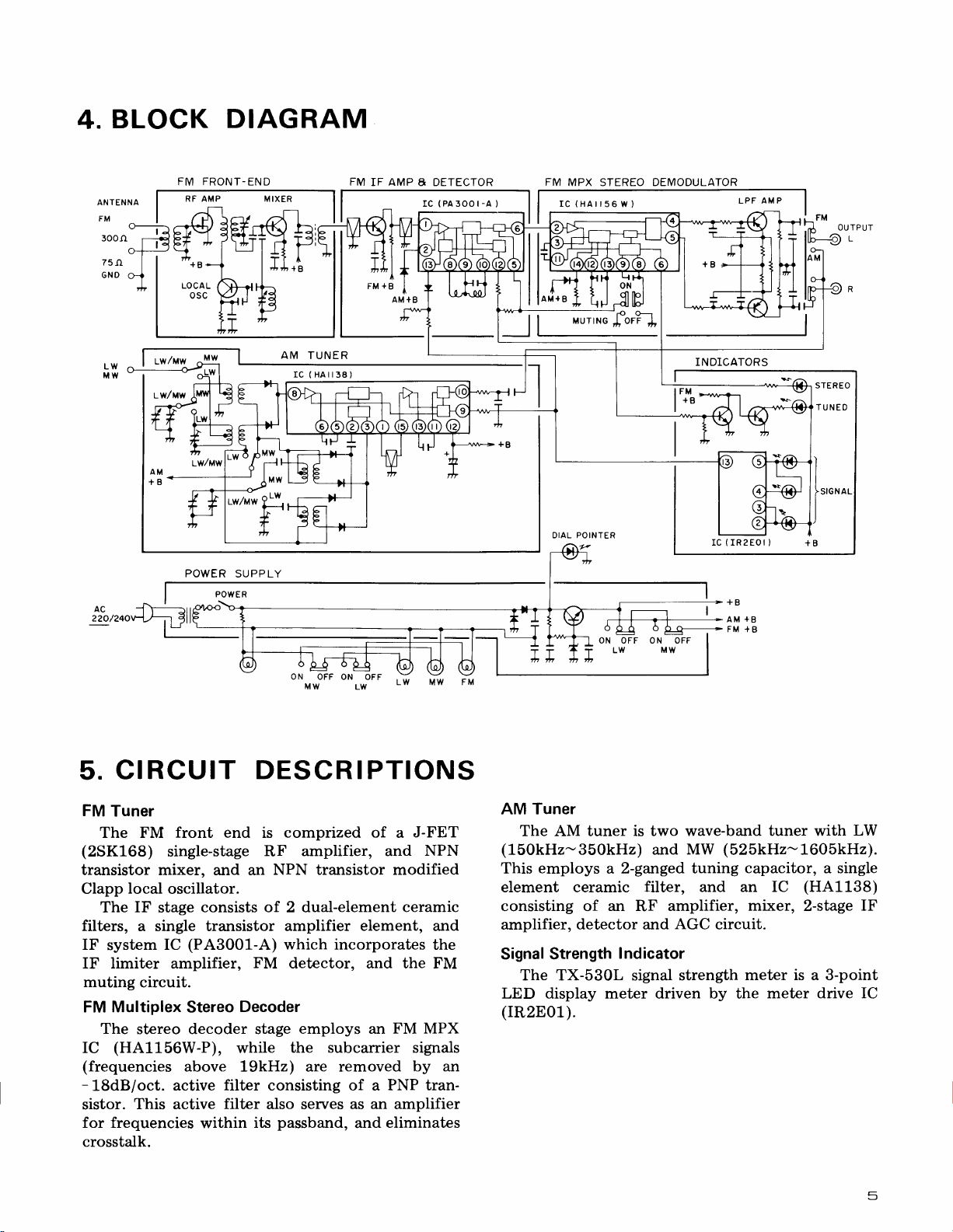
CIRCUIT
5.
FM
Tuner
The FM
(2SK168)
single-stage
front
DESCRIPTIONS
end is
transistor mixer, and an
Clapp
filters,
local
IF
The
a single transistor
IF
system
IF limiter
muting
FM
circuit.
Multiplex
oscillator.
consists of. 2 dual-element
stage
(PA300L-A)
IC
amplifier,
Stereo
FM
Decoder
The stereo decoder stage
(HA1156W-P),
IC
(frequencies
-
18dB/oct.
sistor.
This active
above 19kHz) are removed
active
for frequencies
filter
filter
within
while
its
crosstalk.
ON
OFF
Lfv
.ri"
comprized of
RF amplifier,
a
and
J-FET
NPN
NPN transistor modified
ceramic
amplifier element, and
which incorporates
detector, and the FM
employs an
the subcarrier
FM MPX
signals
by an
an
and
PNP tran-
amplifier
eliminates
consisting of a
also serves as
passband,
Mw
the
FM
AM Tuner
The AM tuner is two wave-band
(150kHz-350kHz)
employs a 2-ganged tuning
This
element ceramic
consisting of
amplifier,
Signal Strength
The TX-530L
an
RF
detector and
Indicator
signal
and
filter,
amplifier,
AGC
strength
MW
and
circuit.
LED display meter driven by the meter
(rR2E01).
tuner with
LW
(525kHz-1605kH2).
capacitor,
an IC
mixer,
a single
(HA1138)
2-stage
IF
meter is a 3-point
drive IC
5
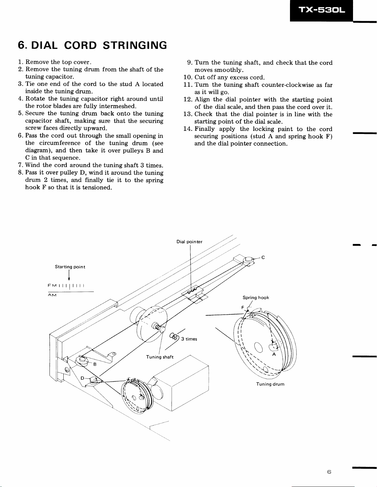
6. DIAL
1.
Remove the top cover.
2. Remove the
CORD STRINGING
tuning drum from
tuning capacitor.
Tie
3.
4.
5. Secure
6.
7. Wind
8.
one end
inside
the
tuning
Rotate
the rotor
the tuning capacitor
blades
the tuning drum back
capacitor
shaft, making
screw faces
Pass
the cord
the
circumference
diagram),
C in that
and then
sequence.
the cord
Pass
it over
drum
2 times,
hook F
so that it is tensioned.
the cord
of
directly
out through the
around the tuning
pulley
and
the
shaft
to the
stud A located
drum.
right
around until
are fully intermeshed.
onto the
sure that the
upward.
small opening
of
the tuning
it
take
over
drum
pulleys
shaft 3 times.
D,
wind it around the
finally
tie it
to
of
tuning
securing
B
tuning
the
spring
the
in
(see
and
9. Turn the tuning
moves
10.
Cut off any excess
11. Tum
as
12.
Align the
of the
13.
Check that the
starting
Finally
1"4.
securing
and the dial
smoothly.
the tuning
will
go.
it
dial
dial
scale, and then
point
apply the locking
positions
pointer
shaft, and
check that
cord.
shaft counter-clockwise
pointer
dial
of the dial
with the starting
pass
the cord
pointer
is in line
scale.
paint
(stud
A
and spring hook F)
connection.
the cord
far
as
point
over it.
with the
to the cord
-I
FM
AM
Star
I
I
Tuning
)-'---t
shaft
Tuning
drum
-
--
 Loading...