

Pioneer TX-130-L Service manual
rrloNeErl'
GD
STEREO
TUNER
TXIISOL
MODEL TX-130L COMES
Type
o
o
o
HE
HB
This
manuel
Ce
Este
service
manual
22OY and24OV Europe model
22OY and24OV
manual
d'instruction
de
servicio trata
CONTENTS
1.
SPECIFICATIONS
2. FRONT
3. BLOCK
4.
C!RCUIT
5. PARTS
6. EXPLODED
7. P.C. BOARD
8.
SCHEMATIC
ELECTRICAL
9.
10. PACKING
11.
DIAL
12. ADJUSTMENTS
PANEL FACILITIES
DIAGRAM
DESCRIPTIONS.
LOCATION
CORD
nEcuce
AJUSTE
.
VIEW
.
CONNECTION DIAGRAM
DIAGRAM
PARTS
STRINGING
IN TWO VERSIONS
Voltago
is
applicable to
se refCre
the HE,
au
del m6todo
. .
LIST. .
mode
de
DISTINGUISHED
HB
types.
de r6glage,
ajuste
escrito
2
3
4
4
5
6
7
9
11
12
13
14
16
18
model
U.K.
en francais.
en espafiol.
Change
Line
1.
2.
3.
4.
of
voltage
Disconnect
Remove the
Change the
former)
11 of
Switch
Voltage
220V
240V
Stick the line
Part No.
AAX-193
AAX.192
FOLLOWS:
AS
Remarks
Line Voltage
can be
the
changed
power
AC
Top cover.
connection
of terminal
No.
assembly A as follows:
Terminal
No.
Green
wire
Blue wire
voltage
Description
22OY label
240V
12
label on
label
ORDER
ARP
with following
cord.
wire
12 and
-099-O
(for power
terminal
Terminal
the rear
No. 11
Blue wire
Green
wire
NO.
steps.
trans-
No.
panel.
PICINEEFI
PICINEEFI
PIoNEEFI
P|ONEEFI
ELECTFICINIC
ELECTFICINICE|
ELEcrFloNlc
ELECTFICINIC€i
tNC. 1925
IUAAI
IEIJFIoPEI
AIJCITFIALIA
CCIFIPCIFIATIGIN
N.v.
E.
Dominguez
Luirhagen-Haven
PTY. LtE.
4-1, Mesuno
St., Long Beach,
9, ao3o Anrwenp,
17AJ184
1-chome,
Califonnie
Boundany Fload,
Mesuno-ku, Tokyo.158,
9OE1O U.S.A.
E}etgium
BnaLside,
Victonia
YL o APR.
Japan
3195, Ausrnatia
Printed in
i982
lapan

1.
SPECIFICATIONS
FM Tuner
Usablesensitivity............
50 dB Quieting
Sensitivity
Signal-to-Noise
Signal-to-Noise
Distortion
Stereo........
Distortion
Stereo........
Capture
Alternate Channel
Stereo
Frequency
Spurious
lmage
lF Resoonse
AM
Suppression
Muting Threshold
Antenna
Tuner Section
LW
Sensitivity
lHF,
Selectivity
Signal-to-Noise
lmage
lF Response
Antenna
Section
Sensitivity
(DlN)
.........
(at
Ratio
(DlN)
Ratio
(at
60 dBf)
(DlN)
Ratio ..........
Selectivity
Seoaration
Response
Response Ratio
Response
Input ....... 300
external antenna
Response
............
Ratio
Ratio..........
Ratio
Ratio
Ratio
..........
Ratio
80 dBf
)
......... Mono;72d8
...... 30 Hz
.........
ohms balanced,
Accessory
.... 10.8dBf
Mono; 17.3
Stereo; 39.2
Mono; 0.85prV
Stereo; 39.8
.. Mono; 75 dB
Stereo;
Stereo;
.......1k{2;Q.2o/o
....... 1kHz,0.2o/o
................
......... 1 kHz;
to 1 5 kHz:!
...........
19.2 dBf
75 ohms
AM looP antenna
(1.9pV)
(4.0
dBf
dBf
pV)
(50
pV)
pV
70
dB
70
dB
...... 1 .0 dB
60 dB
zl0
dB
dB
fr
70 dB
......55dB
..80d8
...... 50
unbalanced
.......50 dB
dB
(5
pV)
....45pV
... 25 dB
...... 40 dB
.. 70 dB
Tuner Section
MW
Sensitivity
lHF, external antenna
Selectivity
Signal-to-Noise
lmage Response
lF Response
Antenna
Ratio
Ratio
Ratio ..........
Audio Section
(100%
FM
AM
MOD) .........
(30%
MOD)
.........
Miscellaneous
Power Requirements
Power Consumption
Dimensions
Weight
(without
Furnished
FM T-type
Antenna
AM
Antenna Catcher
Connection
Operating
NOTE:
Specifications
notrce.
package)
Parts
Antenna
Cord with
Instructions
and design
.......42O
(W)
16-1/2
Pin Plugs
subiect
Accessory
AC22OV
(W)
x 69
x2-3/4
possible
to
....30pV
...25d8
....... 50
looP
AM
650
200
l24OV,
...... 40 dB
mV/3.5
mV/3.5 ka
dB
.. 70 dB
antenna
ka
50/60H2
{Switchable)
........9.5W
(D)
x?26
lHl
(H)
x 8-718
. .. .. . 2.5
........................
kg
...............
................... 1
.................. 1
modification
mm
(D)
(5
............ 1
in
lb 8 oz)
without
'l
1
2.
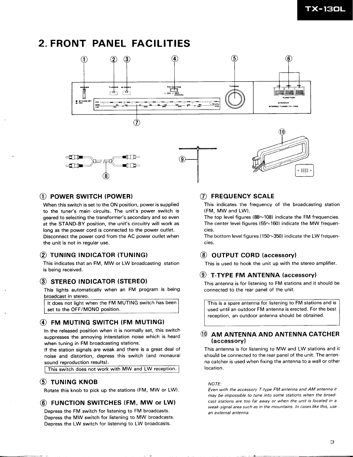
FRONT PANEL FACILITIES
-ilF
cfl
_fr...,.t
* *r"_a'';-
,- HK
@
poweR
O
this switch
When
to the
geared
the
at
STAND-BY
long
as
Disconnect
the
unit
rururruc rNDrcAToR
@
This indicates that
is
being
sreneo
@
lights automatically
This
broadcast
It does
set to
rru MUTTNG
@
In the
suppresses
when tuning
lf the station
noise
sound
This switch
swrrcH
is
to the ON
set
tuner's main circuits.
to selecting
the
is not
the transformer's secondary
position,
power
power
the
in
is connected
cord
cord
regular
use.
FM, MW or LW broadcasting station
an
received.
tNDtcAToR
in stereo.
not light when
the
OFF/MONO
released
and
reproduction
position
the annoying
in FM
signals are
distortion,
does
the FM MUTING
Position.
swtrcH
when
broadcasting stations.
weak
depress
results).
not work
|
{=;
I
(PowER)
position,
The unit's
the unit's circuitry
to the
from the AC
power
(TUNTNG)
(srEREo)
program
when an
interstation
with MW and
FM
(FM
normally set,
it is
noise
there is a
and
this switch
switch
MUTING)
power
power
and so even
will work as
power
outlet when
which
great
(and
LW
is supplied
switch
outlet.
being
is
has been
this switch
is heard
deal of
monaural
reception.
rneouENcY scALE
@
This indicates the frequency of the broadcasting station
is
(FM,
MW and LW).
top level figures
The
The center level figures
cies.
The bottom level f igures ( 150-350) indicate
cies.
ourPUT
@
is
This
r-rYPE
@
This antenna
connected
This
used until
reception,
nnn ANTENNA
@
to hook the unit up
used
is for
to the rear
is a spare antenna
an outdoor
an
(88-1081
coRD
ANTENNA
FM
listening to FM stations
panel
FM antenna
outdoor antenna
indicate the FM frequencies.
(55ru160)
(accessory)
of the unit.
listening to FM stations and
for
ANTENNA
AND
indicate the MW frequen-
with the stereo amplifier.
(accessory)
is erected.
should
the
and
be obtained.
f requen-
LW
it
should
For the best
cATcHER
be
is
(accessory)
listening
This antenna
should be connected
na
catcher
location.
is for
is used
when fixing
to
to the rear
the
MW and
panel
of the unit.
antenna
LW stations and
The
to a wall or other
it
anten-
rurutruc
@
this knob
Rotate
rurucfloN
@
Depress
Depress
Depress
KNoB
pick
to
swlTcHEs
FM
the
the MW switch
the LW switch
switch
the stations
up
(FM,
listening to
for
listening to MW
for
for listening
(FM,
MW or LW)
or LW)
MW
FM broadcasts.
broadcasts.
to LW broadcasts.
NOTE:
Even with
may be impossible
cast
weak-signal
an external
the accessory
stations
antenna.
too far awaY or
are
area such
T-type FM antenna
to tune into some
when the unit
as in the mountains.
and AM antenna
stations
when the broad-
ln cases
located in a
is
like this, use
it
3
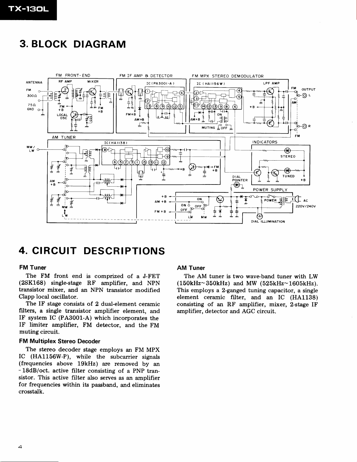
3. BLOCK
DIAGRAM
ANTENNA
FM
300f]
75rI
GND
FM FRONT-
AM TUNER
END
FM
IC(HAil38)
IF AMP
8 DETECTOR
(
PA300t-A
IC
FM
MPX
STEREO
)
(HAlr56w)
rc
DEMODULATOR
IN
DICATORS
IAL
D
POINTER
POWER
ILLUMINATION
STEREO
SUPPLY
4.
CIRCUIT
FM
Tuner
The
FM front
(2SK168)
transistor
Clapp local
The IF
filters,
IF
system IC
single-stage
mixer,
oscillator.
stage consists
a single
IF limiter
muting
circuit.
FM Multiplex
The
stereo
(HA1L56W-P),
IC
(frequencies
-
18dB/oct.
sistor. This
for
frequencies
crosstalk.
DESCRIPTIONS
end
is comprized
RF amplifier,
and
an
of.
transistor
(PA3001-A)
amplifier, FM
Stereo
decoder
above
active filter
active filter
Decoder
stage employs
while
19kHz)
consisting
also serves
within its
NPN
transistor
2 dual-element
amplifier
which
detector,
the
are
element,
incorporates
ffid
subcarrier
removed
of a PNP
as an
passband,
and
J-FET
of a
and
modified
ceramic
the
FM
an
signals
by an
amplifier
eliminates
NPN
and
the
FM
MPX
tran-
AM
Tuner
The
AM
tuner is two
(150kHz-350kHz)
This employs
and MW
2-ganged
a
element ceramic filter,
consisting
amplifier,
of an
amplifier, mixer,
RF
detector and AGC
wave-band tuner
(525kHz-1605kH2).
tuning capacitor,
and an IC
circuit.
$rith LW
a single
(HA1138)
2-stage IF

5.
PARTS
Front
Panel
Top
cover
ANE-357
View
LOCATION
NO?ES;
o
Parts
c
The
safety
designation.
o
For
**
and *.
**
This classification
number,
without
I
your
GENERALLY
part
marh
found
of the
factor
Parts
Stoch Control, the
temperature,
number
shall be adjusted by each
cannot be
on
part.
MOVES FASTER
humidity, e tc.
component
some
Therefore,
when
fast
supplied.
moving items
THAN *.
parts
replacing,
distributor
indicates
be
sure
are indicated
because
the importance
parts
to use
it depends
Knob
AAD48O
with
(FM
B
of
of the
identical
the marhs
model
on
MUTING)
Knob
AAD417
Front
ANM-208
(POWER)
A
panel
Rear Panel
Terminal
(ANTENNA)
AKA.O18
4P
Top View
View
@@GA
-i-
t
Panel
stay
ANR.522
Knob
AAA.O79
Terminal
(OUTPUT}
AKB.O77
power
AC
ADG-062
ADG-063
assembly
(TUNINGI
2P
cord
(HE
typsl
(HB
typel
a*
A**
Power
transformer
ATT.881
Push
switch
ASG-s16
Push
switch
ASG-313
(POWER)
(
**
Push
switch
ASX-190
Tuning
AXA-35O
Tuner
assembly
GWE-186
(FUNCTION)
shaft asembly

EXPLODED
6.
VIEW
Mark
A
A
No.
1. AN
2.
*
3. AEL-165
4.
5.
b.
7.
8.
9.
10.
11.
**
12.
13.
14.
15.
16. AXA-350
17.
18. ATT-881
19.
20. AEC-784
Part
No.
E-357
BBZ30P080FZK
AAD417
PMZ30P060FMC
AAG-237
ANM.208
AAD.48O
AAA-O79
wA73F1
ABN-067
AEK4O6
ANR-522
AAF-1
ABA-252
18U050
17
Description
Top
cover
Screw 3x8
Lamp assembly
Knob
Screw 3x6
Dial
Front
Knob
Knob
Washer
Nut M7
Fuse
Panel
Dial
Tuning
Screw
Power
Foot
(POWER)
A
scale
panel
(FM
B
(TUNING)
(T630mA)
stay assembly
pointer
assembly
shaft assembly
transformer
assembly
MUTING)
Mark
A
Part
No.
21. ADG-062
22.
51.
52.
53.
54.
55.
56.
57.
58.
59.
60.
61.
62.
63.
64.
65.
No.
ADG-063
GwE-186
Description
power
AC
power
AC
Tuner
assembly
Switch assembly A
joint
Switch
Pulley
assembly
Plate
LED
assembly
Switch assembly B
Smoother
Pulley
holder
Switch assembly
Chassis
panel
Rear
Tuning drum
Pulley
assembly
Nylon rivet
Remote
cord
cord
wire
(HE
(HB
typel
type)
-
C
21
)4=:\,
M
fy
\r'"
z@
sJ?.-
-
5
-'v-z
e-{t
xr/
-
o
 Loading...