

Pioneer TS4 Service Manual
CANAL PLUS TUNER
TS4
THIS MANUAL IS APPLICABLE TO THE FOLLOWING MODEL(S) AND TYPE(S).
Type
NYXK/FR AC230V
Model
TS4
Power Requirement Remarks
ORDER NO.
ORDER NO.
ARP3039
CONTENTS
1. SAFETY INFORMATION .............................................. 2
2. EXPLODED VIEWS AND PARTS LIST........................3
3. BLOCK DIAGRAM AND SCHEMATIC DIAGRAM........ 5
4. PCB CONNECTION DIAGRAM.................................. 24
5. PCB PARTS LIST ....................................................... 30
6. GENERAL INFORMATION ........................................ 33
6.1 DIAGNOSIS.......................................................... 33
6.1.1 TEST SOFTWARE ........................................ 33
6.1.2 SELF-DIAGNOSIS MODE............................. 36
6.1.3 TROUBLE SHOOTING ................................. 43
6.2 IC .......................................................................... 55
7. PANEL FACILITIES AND SPECIFICATIONS............ 70
PIONEER CORPORATION 4-1, Meguro 1-Chome, Meguro-ku, Tokyo 153-8654, Japan
PIONEER ELECTRONICS SERVICE, INC. P.O. Box 1760, Long Beach, CA 90801-1760, U.S.A.
PIONEER ELECTRONIC (EUROPE) N.V. Haven 1087, Keetberglaan 1, 9120 Melsele, Belgium
PIONEER ELECTRONICS ASIACENTRE PTE. LTD. 253 Alexandra Road, #04-01, Singapore 159936
c
PIONEER CORPORATION 1999
O- SZS AUG. 1999 Printed in Japan
TS4
1. SAFETY INFORMATION
This service manual is intended for qualified service technicians ; it is not meant for the casual do-ityourselfer. Qualified technicians have the necessary test equipment and tools, and have been trained
to properly and safely repair complex products such as those covered by this manual.
Improperly performed repairs can adversely affect the safety and reliability of the product and may
void the warranty. If you are not qualified to perform the repair of this product properly and safely, you
should not risk trying to do so and refer the repair to a qualified service technician.
WARNING
This product contains lead in solder and certain electrical parts contain chemicals which are known to the state of California to cause
cancer, birth defects or other reproductive harm.
Health & Safety Code Section 25249.6 – Proposition 65
NOTICE
(FOR CANADIAN MODEL ONLY)
Fuse symbols (fast operating fuse) and/or (slow operating fuse) on PCB indicate that replacement parts must
be of identical designation.
REMARQUE
(POUR MODÈLE CANADIEN SEULEMENT)
Les symboles de fusible (fusible de type rapide) et/ou (fusible de type lent) sur CCI indiquent que les pièces
de remplacement doivent avoir la même désignation.
(FOR USA MODEL ONLY)
1. SAFETY PRECAUTIONS
The following check should be performed for the
continued protection of the customer and service
technician.
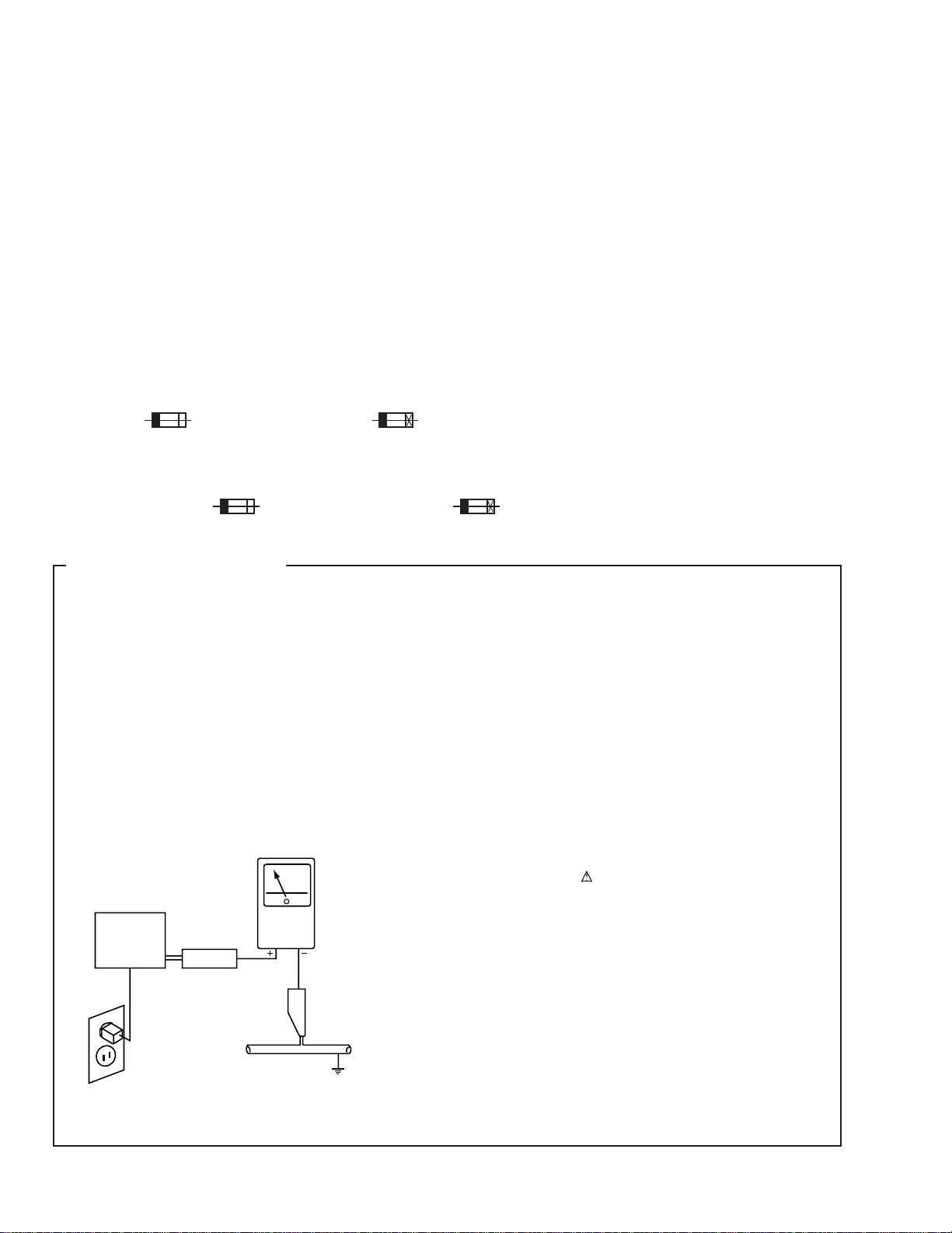
LEAKAGE CURRENT CHECK
Measure leakage current to a known earth ground (water
pipe, conduit, etc.) by connecting a leakage current tester
such as Simpson Model 229-2 or equivalent between the
earth ground and all exposed metal parts of the appliance
(input/output terminals, screwheads, metal overlays, control
shaft, etc.). Plug the AC line cord of the appliance directly
into a 120V AC 60Hz outlet and turn the AC power switch
on. Any current measured must not exceed 0.5mA.
Reading should
not be above
0.5mA
Earth
ground
Device
under
test
Also test with
plug reversed
(Using AC adapter
plug as required)
Leakage
current
tester
Test all
exposed metal
surfaces
ANY MEASUREMENTS NOT WITHIN THE LIMITS
OUTLINED ABOVE ARE INDICATIVE OF A POTENTIAL
SHOCK HAZARD AND MUST BE CORRECTED BEFORE
RETURNING THE APPLIANCE TO THE CUSTOMER.
2. PRODUCT SAFETY NOTICE
Many electrical and mechanical parts in the appliance
have special safety related characteristics. These are
often not evident from visual inspection nor the protection
afforded by them necessarily can be obtained by using
replacement components rated for voltage, wattage, etc.
Replacement parts which have these special safety
characteristics are identified in this Service Manual.
Electrical components having such features are identified
by marking with a
in this Service Manual.
The use of a substitute replacement component which does
not have the same safety characteristics as the PIONEER
recommended replacement one, shown in the parts list in
this Service Manual, may create shock, fire, or other hazards.
Product Safety is continuously under review and new
instructions are issued from time to time. For the latest
information, always consult the current PIONEER Service
Manual. A subscription to, or additional copies of, PIONEER
Service Manual may be obtained at a nominal charge from
PIONEER.
on the schematics and on the parts list
AC Leakage Test
2
2. EXPLODED VIEWS AND PARTS LIST
NOTES:•Parts marked by "NSP" are generally unavailable because they are not in our Master Spare Parts List.
The mark found on some component parts indicates the importance of the safety factor of the part.
•
Therefore, when replacing, be sure to use parts of identical designation.
Screws adjacent to mark on the product are used for disassembly.
•
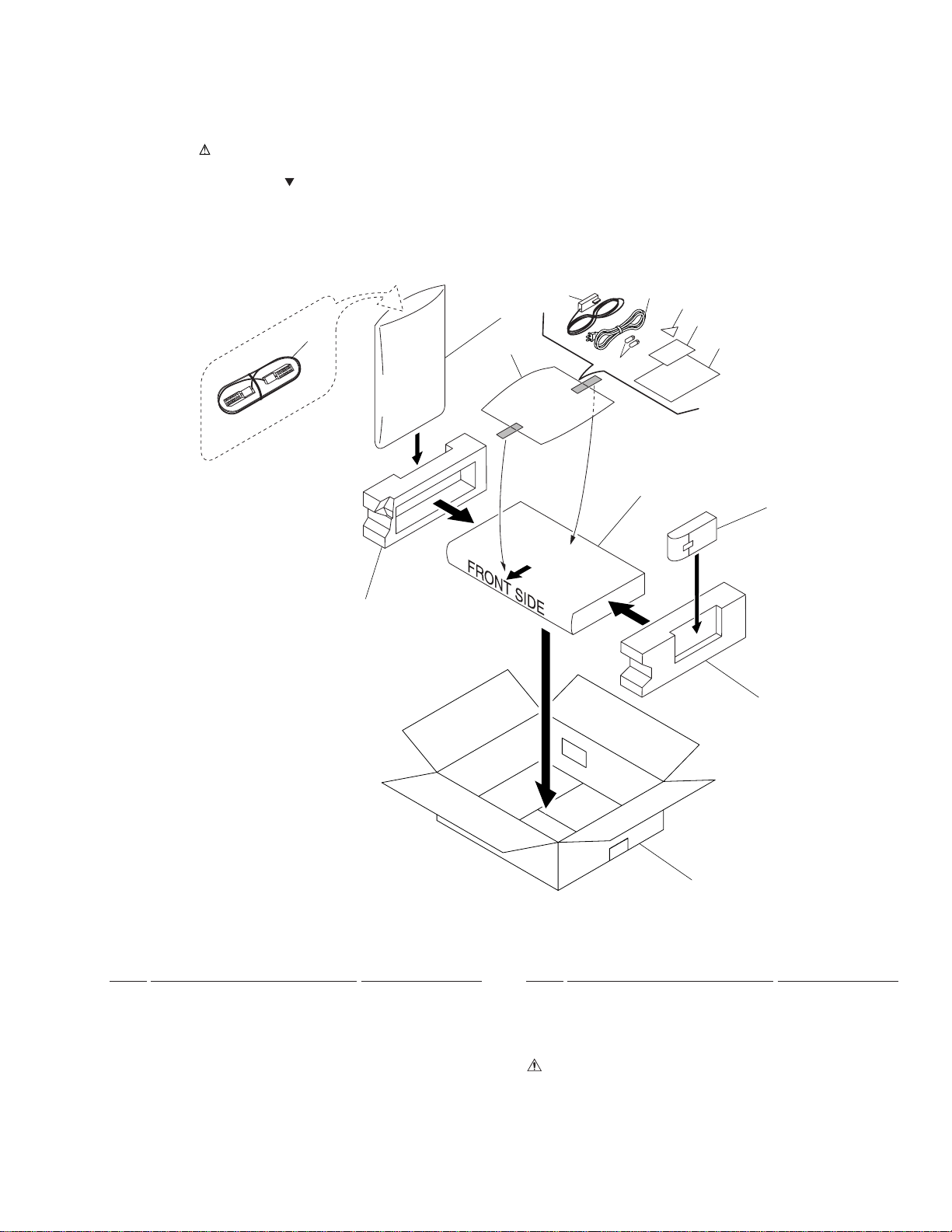
2.1 PACKING
TS4
14
8
9
5
13
12
10
11
7
6
4
3
2
• PACKING PARTS LIST
Mark No. Description Part No.
1 PACKING CASE(PAP) BHD1369
2 SIDE PAD R BHA1147
3 REMOTE CONTROL UNIT BXD1010
4 SHEET AHG1153
5 SIDE PAD L BHA1146
NSP 6 BATTERY (R03) 2P VEM1018
7 INSTRUCTION MANUAL
(French) BRC1003
1
Mark No. Description Part No.
8 POLYETHYLENE BAG Z21-038
9 SCART CABLE (1m:Black) BDH1018
NSP 10 STICKER BAX1271
11 MODEM APPROVAL CARD BRM1022
12 AC POWER CORD(2m:Black)BDG1035
NSP 13 CATALOGUE BAG BHG1047
14 MODEM CABLE (10m:White) BDH1014
3
TS4
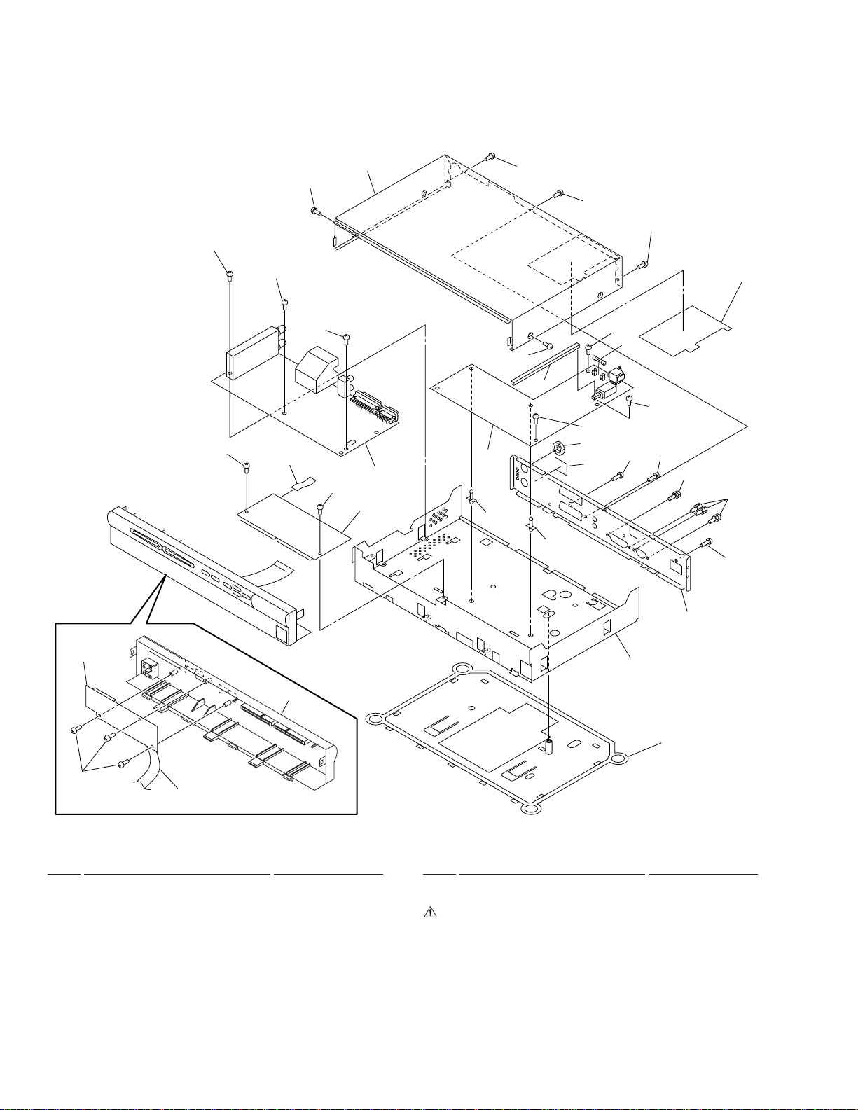
2.2 EXTERIOR SECTION
19
19
19
15
19
19
19
18
19
19
19
17
19
13
19
14
19
19
12
6
5
7
11
10
7
19
19
16
16
19
2
1
19
8
EXTERIOR PARTS LIST
Mark No. Description Part No.
1 FRONT PANEL ASSY BMB1071
2 FRONT ASSY BWE1079
3 PLASTIC BASE(PLS) BMA1001
4 CHASSIS(MET) BNA1149
5 CARD ASSY BWE1080
6 MAIN ASSY(FRANCE) BWE1055
7 PCB SUPPORT AEC1215
8 20P FFC(J1) BDD1032
9 REAR PANEL(MET) BNC1137
10 NAME LABEL(PAP) BAL1366
9
4
3
Mark No. Description Part No.
11 WASHER FACED NUT BBN1005
12 POWER ASSY BXF1112
13 FUSE (F101: T2AH250V) REK1101
14 JOINT BMR1133
15 12P FFC(J2) BDD1033
16 HEXAGON HEADED SCREW BBA1059
17 BARRIER(PLS) BEC1173
18 BONNET CASE(MET) BNE1090
19 SCREW BBZ30P080FZK
4
5
678
3. BLOCK DIAGRAM AND SCHEMATIC DIAGRAM
TS4
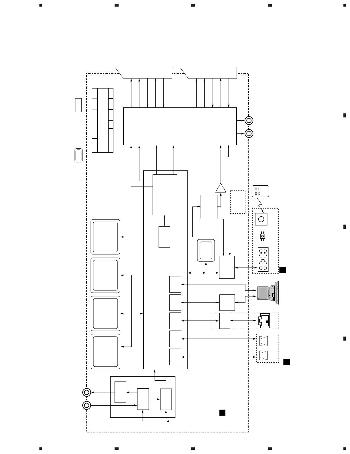
3.1 BLOCK DIAGRAM
: KEY PARTS: MEMORYS
POWER SUPPLY
SWITCHING & SERIES
AC CLK +30V +24V/+19V +24V +12V
POW 1 PC5V +5V +5.5V +3.3V +8V
Note : When ordering service parts, be sure to refer to "EXPLODED VIEWS
and PARTS LIST" or "PCB PARTS LIST".
TV SCART VCR SCART
R/G/B
R/G/B
CVBS
PAL C
CVBS
AUDIO L/R
AUDIO L/R
PAL/
PAL Y
SECAM
D/A PAL
TELETEXT
CVBS
SECAM
ST
STV6411A
Volume control
AV SWITCH with
CVBS
PAL Y
IC4001
PAL C
AK4319
AUDIO D/A
CVBS
18-BIT
AUDIO L/R
L/R
LPF
IC4002
AUDIO L/R
C
2
I
SLOW
SWITCHING
CIRCUIT
R
L
RCA PIN JACK
REMOTE
CONTROLLER
IR
RECEIVER
A
B
SDRAM
RF in RF out
DIREDCT
x1
16Mbit/16bit
and Graphic)
(for MPEG Decode
II
x1
FLASH
(for DATA)
4Mbit/16bit
x1
FLASH I
16Mbit/16bit
(for BOOT/API)
x1
DRAM
(for CPU)
16Mbit/16bit
CONV.
NIM
IC3005
IC3002
IC3001
IC3003
Diseqc
Cont.
16bit bus
16bit bus
A/V
MPEG
16Kbit
IC6005
EEPROM
C
2
IC2001
STi5510
I/F
IEEE 1284
I/F
RS232
I/F
MODEM
I/F 2
Card
I/F 1
SGS-THOMSON <OMEGA>
TUNER
Card
DEMUX CPU DESCRAMBLER
FEC
QPSK,
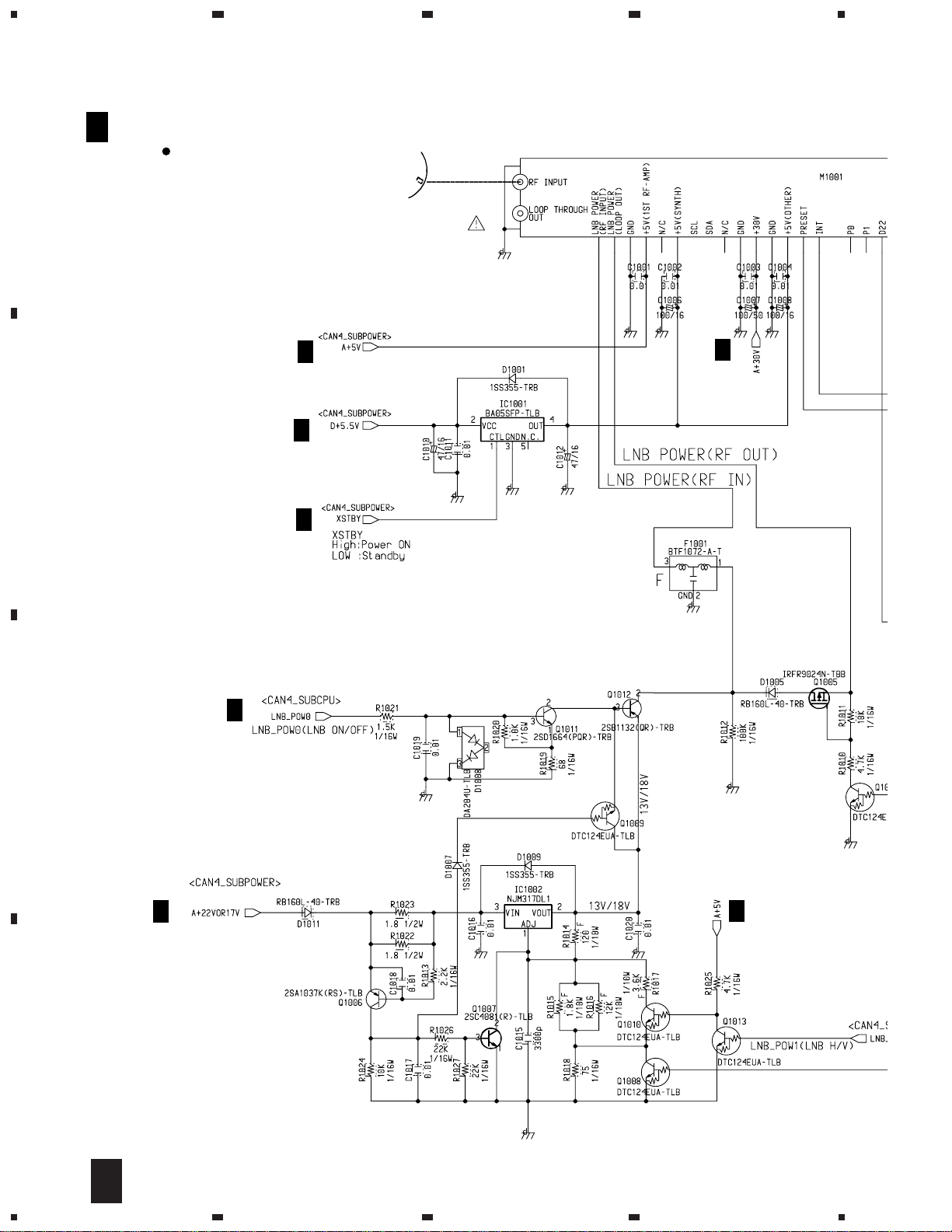
M1001 BXF1108
I
C
2
I
IC6001
Sub CPU
uPD78013BY
IC5001
DRIVER
RS232C
V23
MODEM
MAIN ASSY
(BWE1055)
A
KEYS4-DIGIT LED
FRONT ASSY
B
TEL JACK
CARDS
CA BANK
(BWE1079)
CARD ASSY
(BWE1080)
C
C
D
5
5
6
7
8
1
0
1
0
L
23
TS4
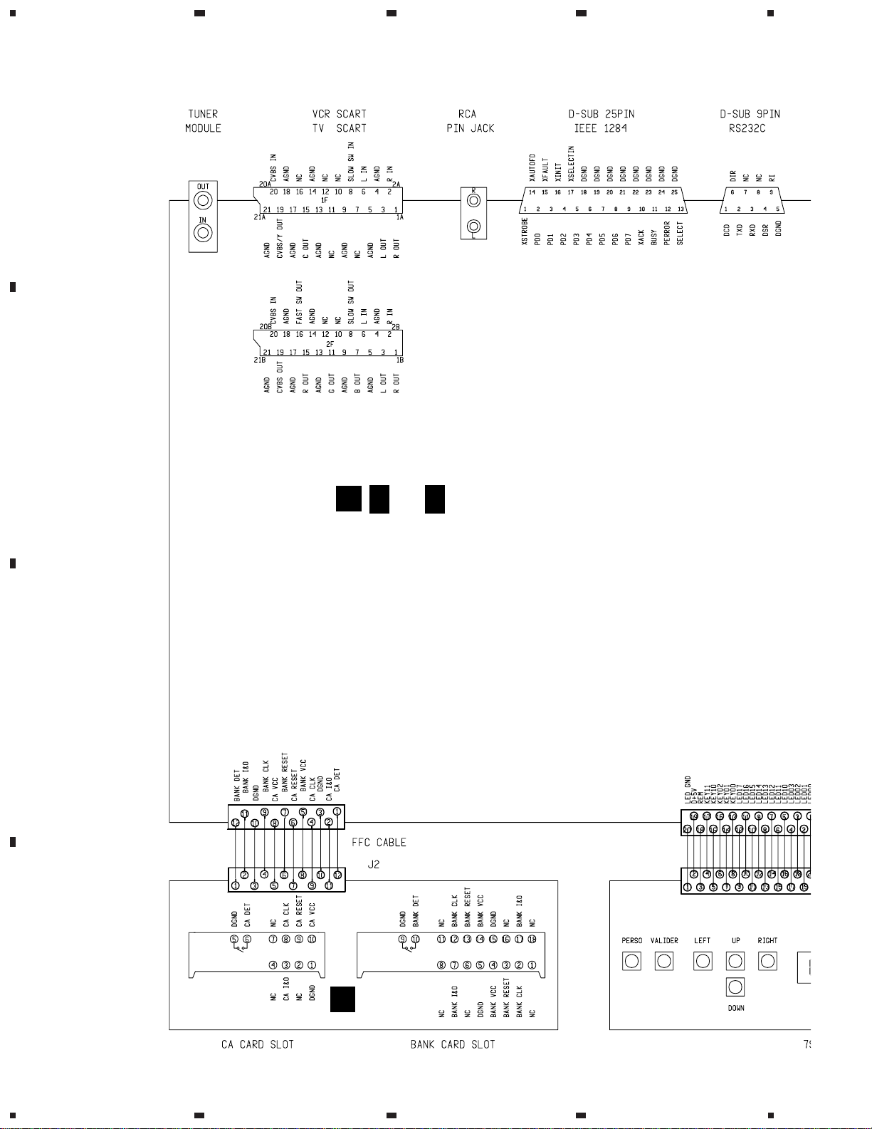
3.2 OVERALL CONNECTION DIAGRAM
A
4
CN4001-1
BKN1019
M1001
BXF1108
CN4001-2
BKN1019
B
(
A
A
1/6-
A
)
6/6
JA4002
BKB1017
MAIN ASSY(BWE1055)
CN5005
BKP1123
CN5
BKP1
CHDEC BLOCK : B1E1055
DMXCPU BLOCK : B2E1055
MEMORY BLOCK : B3E1055
ANALOG AV BLOCK : B4E1055
IO/MODEM BLOCK : B5E1055
SUBPWR/CPU BLOCK : B6E1055
C
CN2003
9604S-12C
BDD1033
CN8503
9604S-12C
CN6001
9604S-20C
CN8001
9604S-20F
CARD ASSY
BWE1080
S8004
D8
BE
S8006
S8003 S8002
D
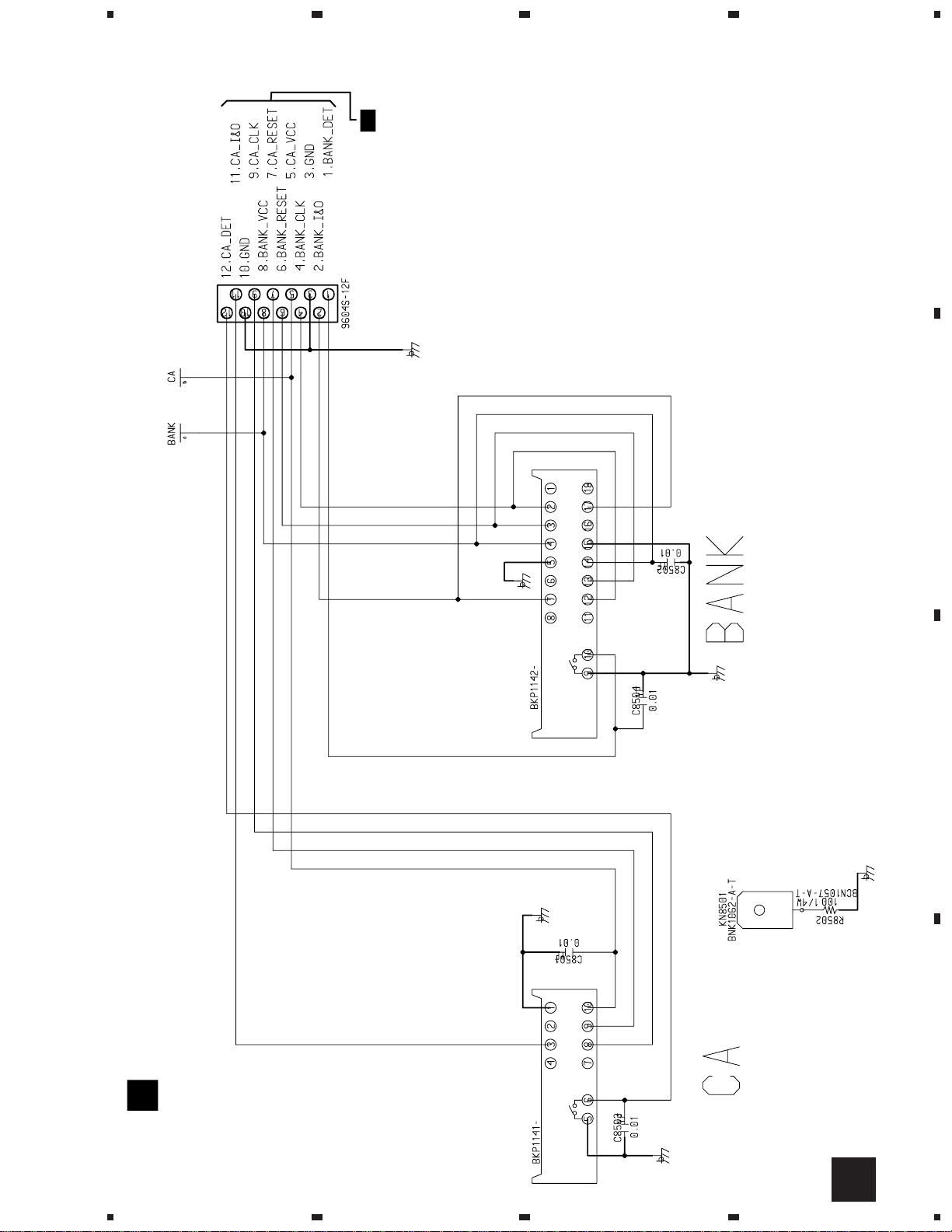
CN8502
BKP1141
CN8501
BKP1142
C
S8001
S8005
6
1234
5
678
TS4
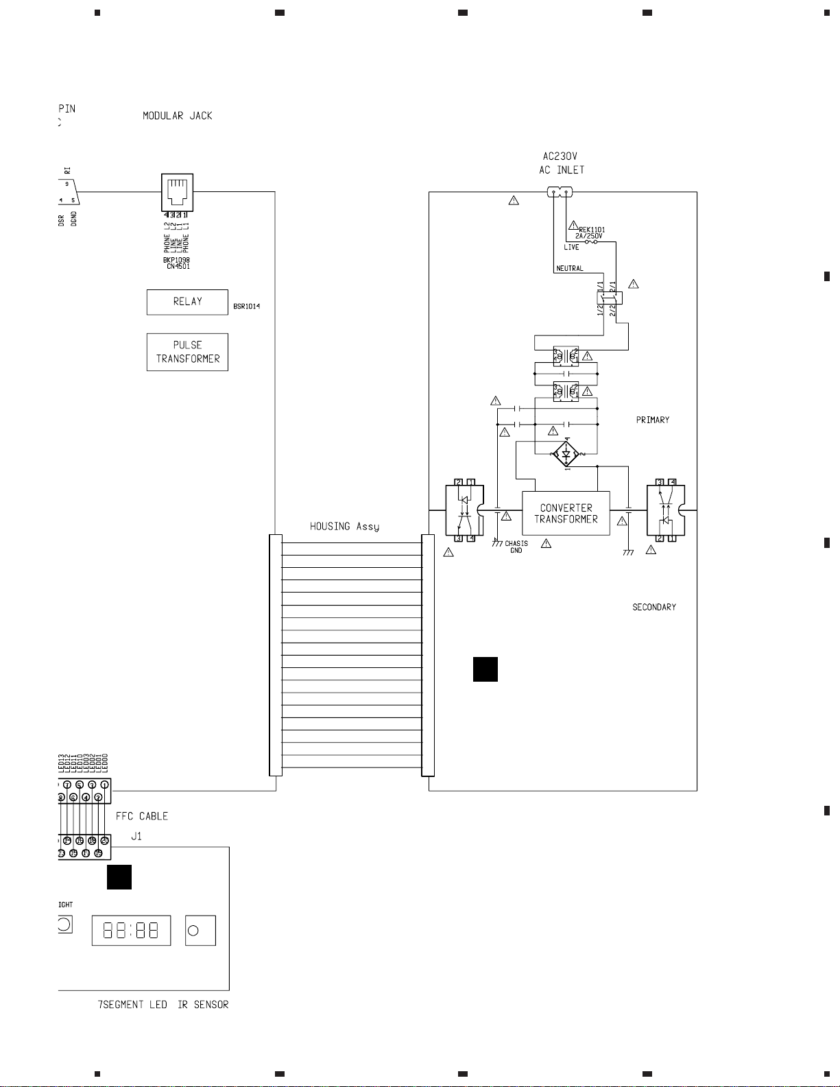
A
CN5004
BKP1122
CN5003
BKP1137
RY5001
T5001
BTX1032
GND
+5.5V
GND
GND
GND
GND
POW1
+3.3V
+3.3V
+3.3V
AC_CLK
+5V
+5VReturn
+8V
+24V
+12V
+24/19V
GND
+30V
CN6002
BKP1120
^
%
$
@
!#
~
-=
0
9
8
67
5
4
3
2
1
CN201
CN101
F101
SW1
L101
C101
C114
T101
L102
B
D101-D104
C116
PC101
C112
C111
C113
1
PC102
2
3
4
5
67
8
9
0
-=~
POWER ASSY
D
BXF1112
C
!#
@
$
%
^
004
B
D8001
BEL1037
BDD1032
FRONT ASSY
BWE1079
M8001
BXX1026
5
D
7
6
7
8
1
8
TS4
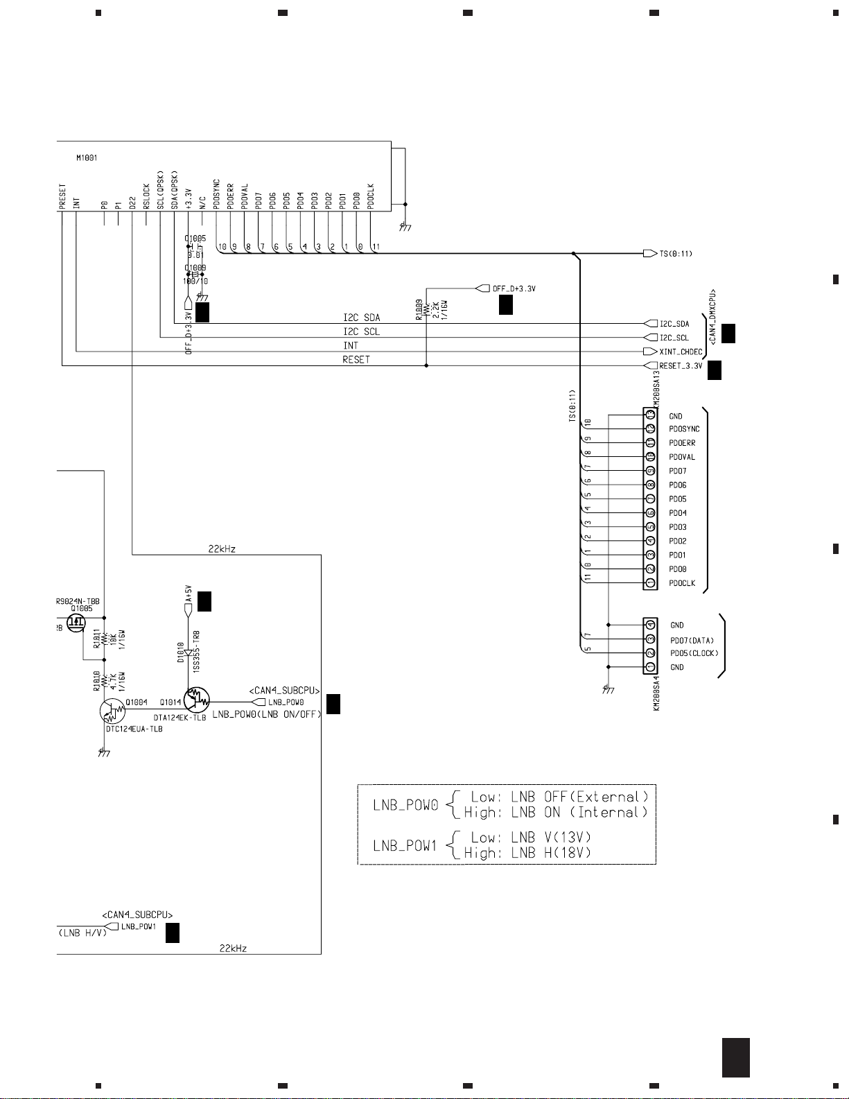
3.3 MAIN ASSY(1/6)
23
4
A 1/6
A
B
MAIN ASSY (1/6) (BWE1055)
CHDEC BLOCK
A
6/6
A
6/6
A
6/6
A
BXF110
6/6
A
6/6
C
A
A
6/6
D
6/6
1/6
A
8
1234
BXF1108
5
DIGITAL TUNER MODULE
A
6/6
678
TS4
A
Not Used
A
6/6
A
2/6
A
6/6
A
6/6
A
6/6
CN1002
B
Not Used
Not Used
C
CN1001
A
6/6
5
D
1/6
A
6
7
8
9
1
TS4
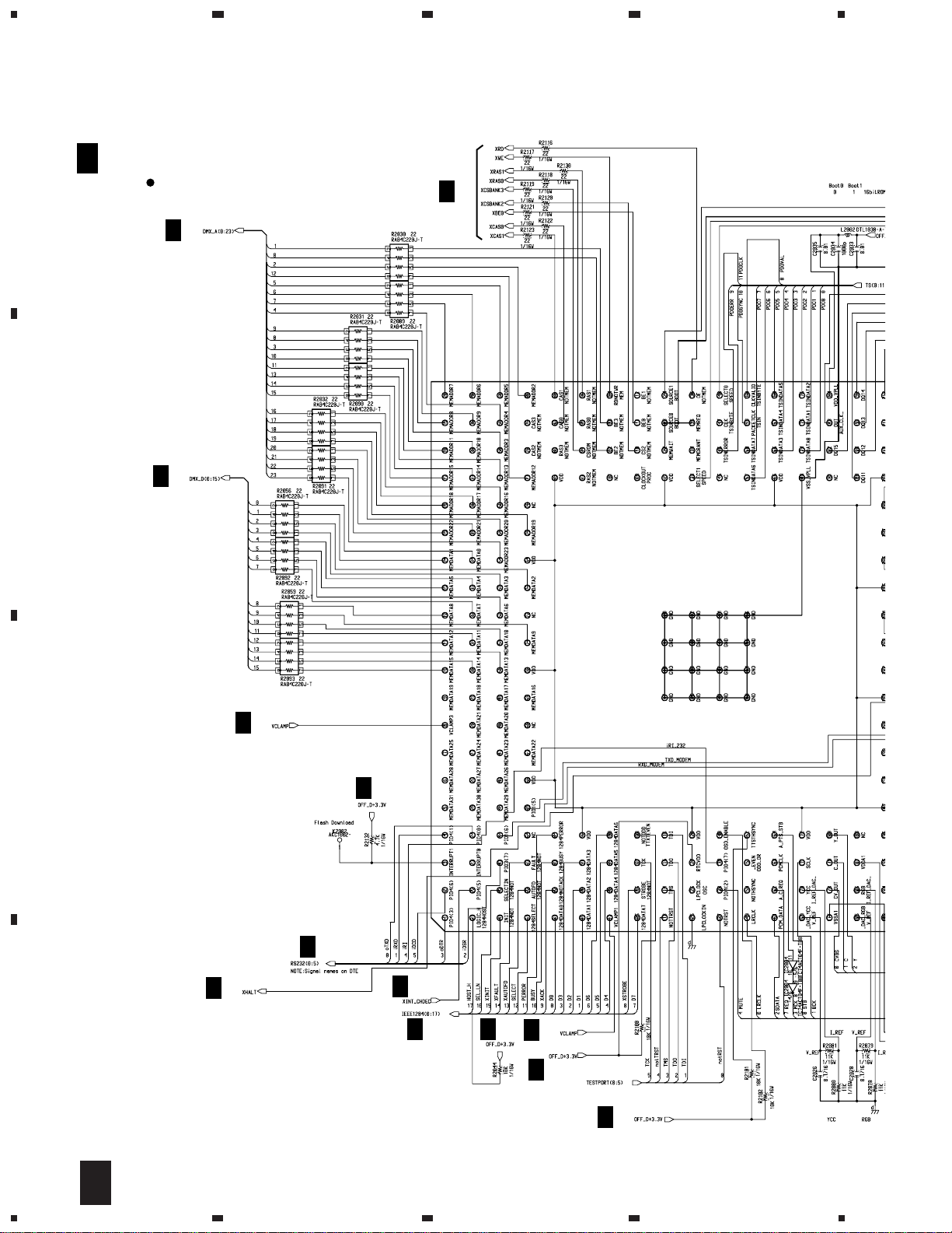
3.4 MAIN ASSY(2/6)
23
4
A
B
A 2/6
MAIN ASSY (2/6) (BWE1055)
DMXCPU BLOCK
A
3/6
A
3/6
A
3/6
IC2001 DEMUX CPU DESCRAMBLER
STI5510
A
6/6
C
A
6/6
A
5/6
A
A
6/6
D
1/6
A
5/6
A
6/6
A
A
6/6
6/6
A
6/6
10
2/6
A
1234
5
678
TS4
A
A
6/6
A
6/6
Not Used
A
5/6
A
A
3/6
A
6/6
6/6
A
3/6
A
6/6
A
3/6
A
6/6
A
3.3 1/2W
6/6
3.3 1/2W
A
6/6
CN2002
Not Used
B
C
A
A
6/6
A
1/6,4/6,6/6
A
A
4/6
6/6
A
6/6
A
6/6
A
6/6
6
A
4/6
5
6/6
A
6/6
7
A
6/6
CN2003
A
2/6
8
CN8503
C
D
11
1
TS4
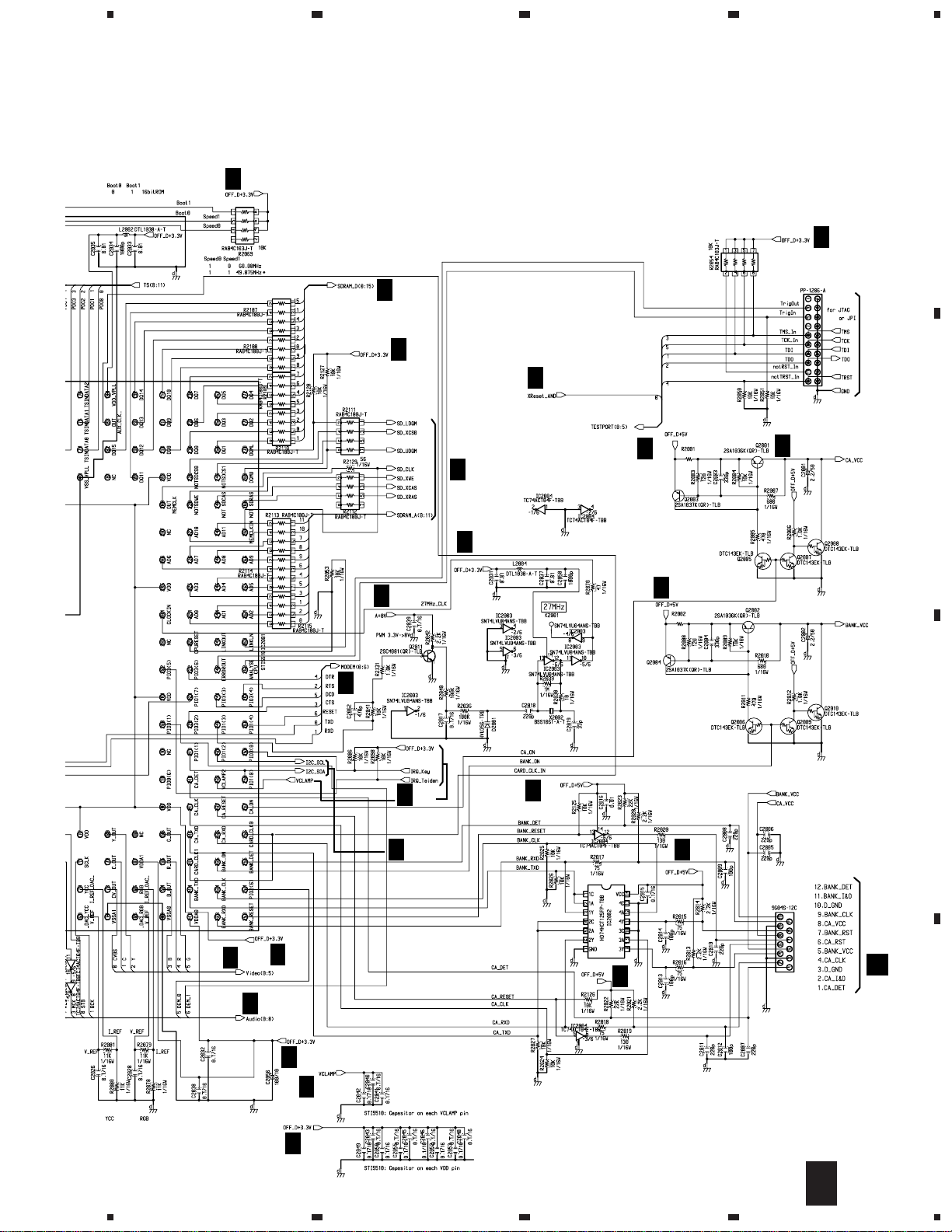
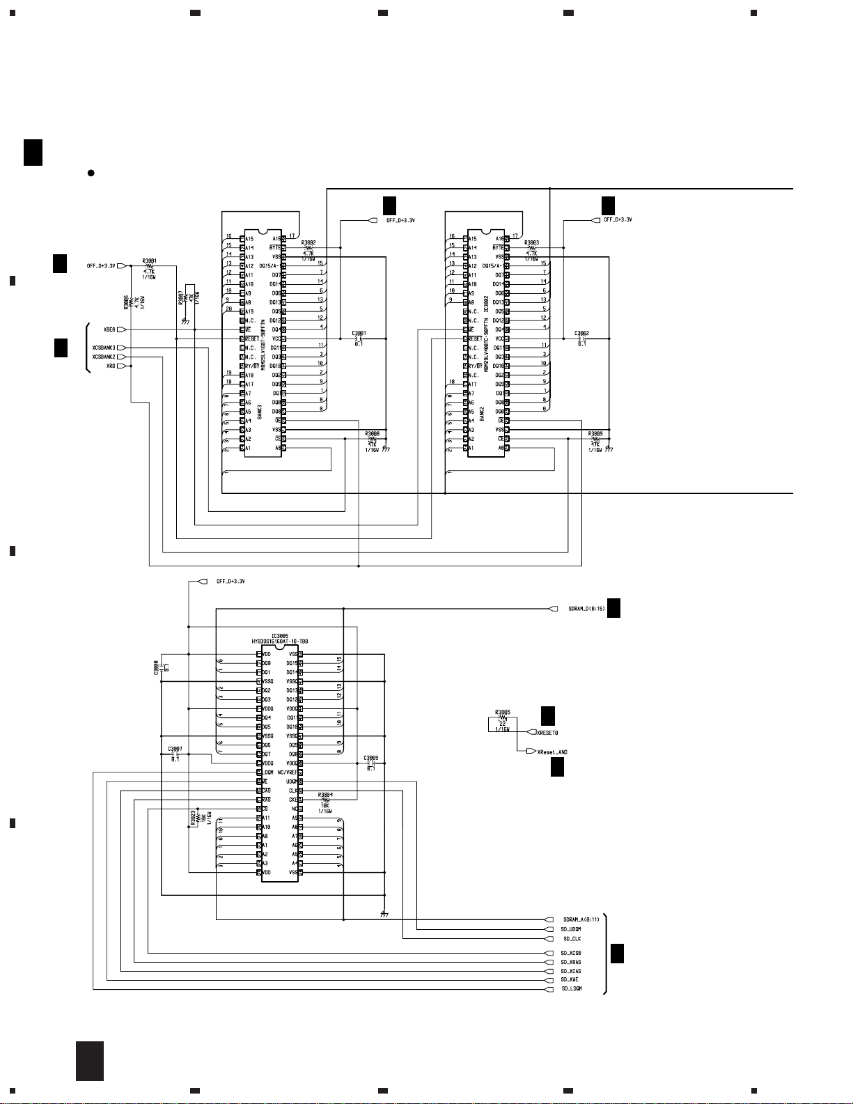
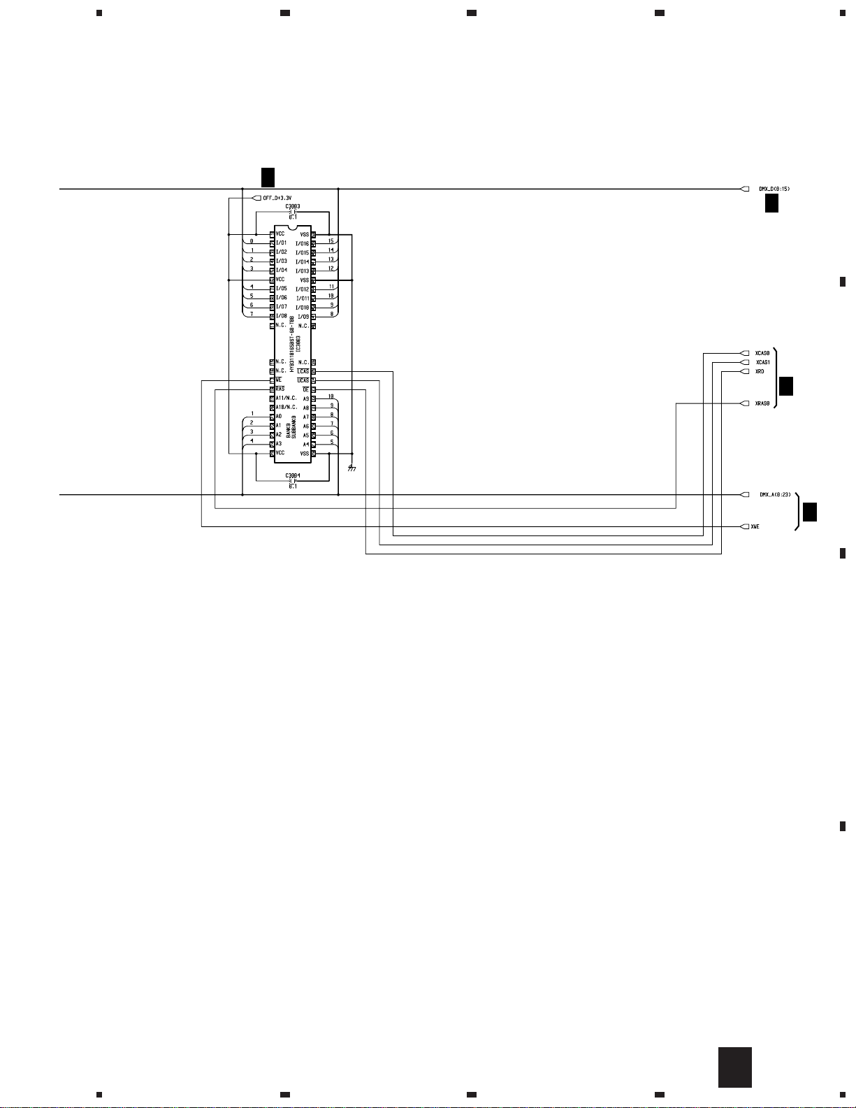
3.5 MAIN ASSY(3/6)
23
4
A
A 3/6
B
MAIN ASSY (3/6) (BWE1055)
MEMORY BLOCK
IC3001 : 16M FLASH
A
6/6
A
2/6
IC3001
A
6/6
IC3002 : 4M FLASH
A
6/6
A
2/6
C
A
3/6
A
2/6
IC3005 : 16M SDRAM
A
D
2/6
12
3/6
A
1234
5
678
TS4
IC3003 : 16M DRAM
A
6/6
A
2/6
A
2/6
A
A
B
2/6
C
D
13
3/6
A
5
6
7
8
1
TS4
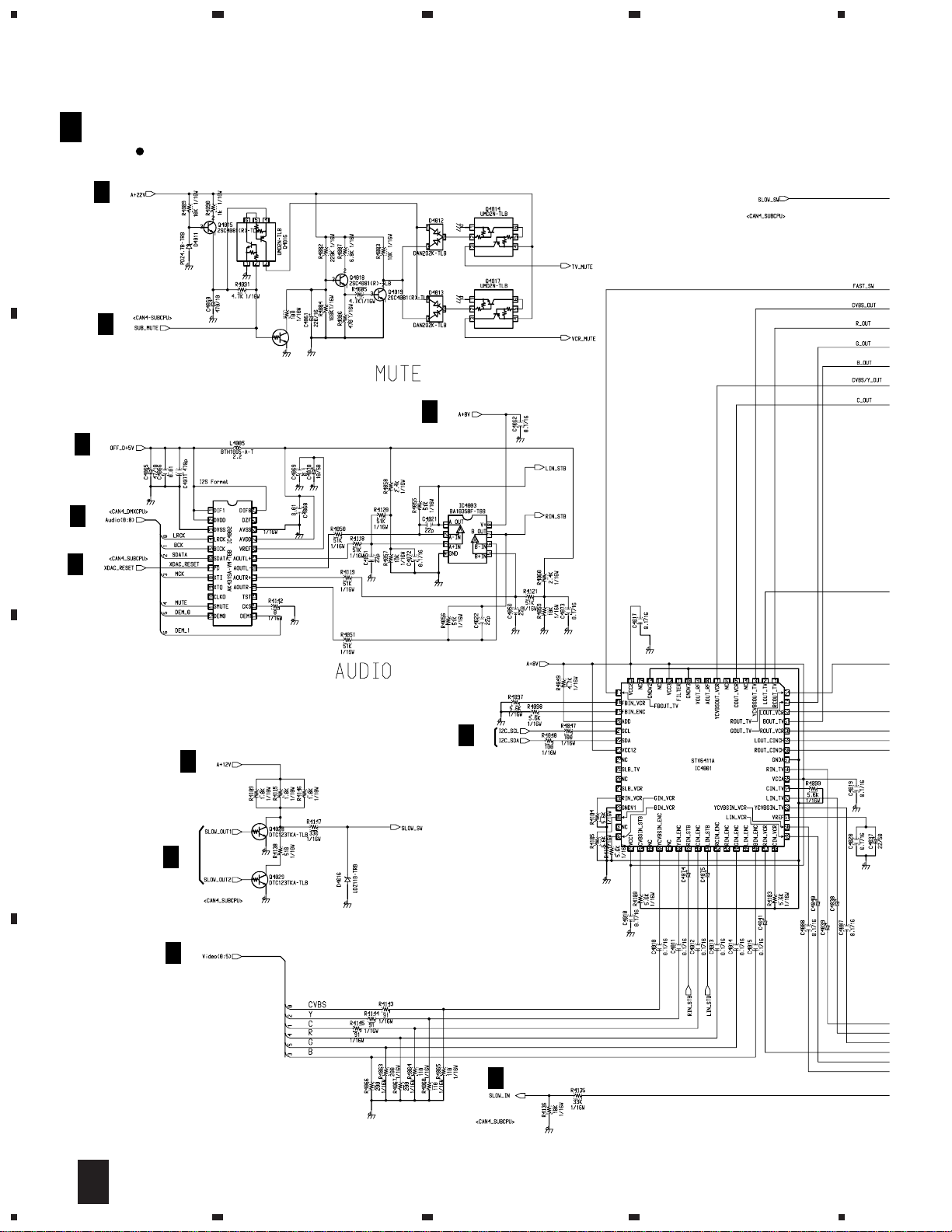
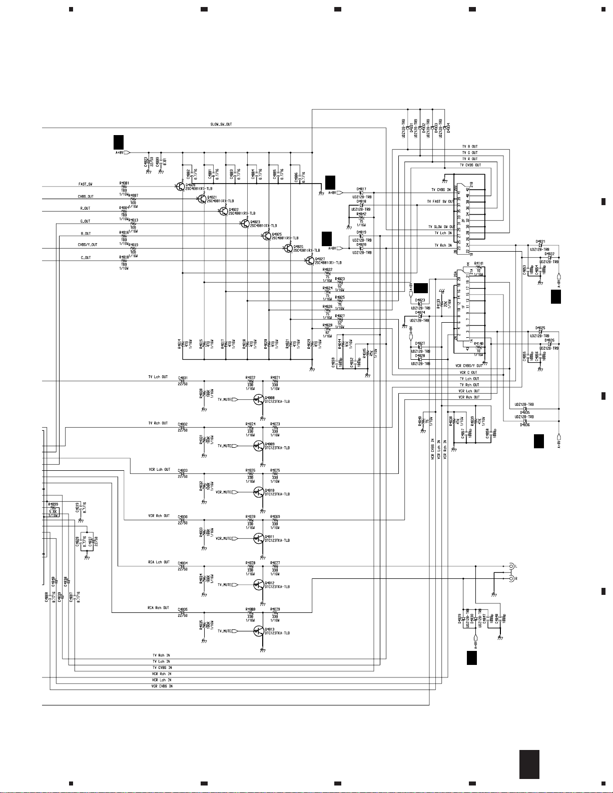
3.6 MAIN ASSY(4/6)
23
4
A 4/6
A
A
B
A
2/6
A
6/6
MAIN ASSY (4/6) (BWE1055)
ANALOG AV BLOCK
A
6/6
A
6/6
Q4030
DTC124TKA-TLB
6/6
R4148
A
6/6
IC4002 : DAC
A
2/6
A
A
A
6/6
2/6
6/6
A
6/6
C
D
IC4001 : AV SWITCH
2.2/50
2.2/50
2.2/50
2.2/50
2.2/50
2.2/50
14
4/6
A
1234
A
6/6
5
678
TS4
A
A
6/6
A
6/6
CN4001-2
BKN1019
CN4001-1
6/6
A
A
6/6
B
2.2/50
2.2/50
2.2/50
BKN1019
RCA OUT
BKB1017
JA4002
A
6/6
C
A
6/6
D
15
4/6
A
5
6
7
8
1
D
23
4
TS4
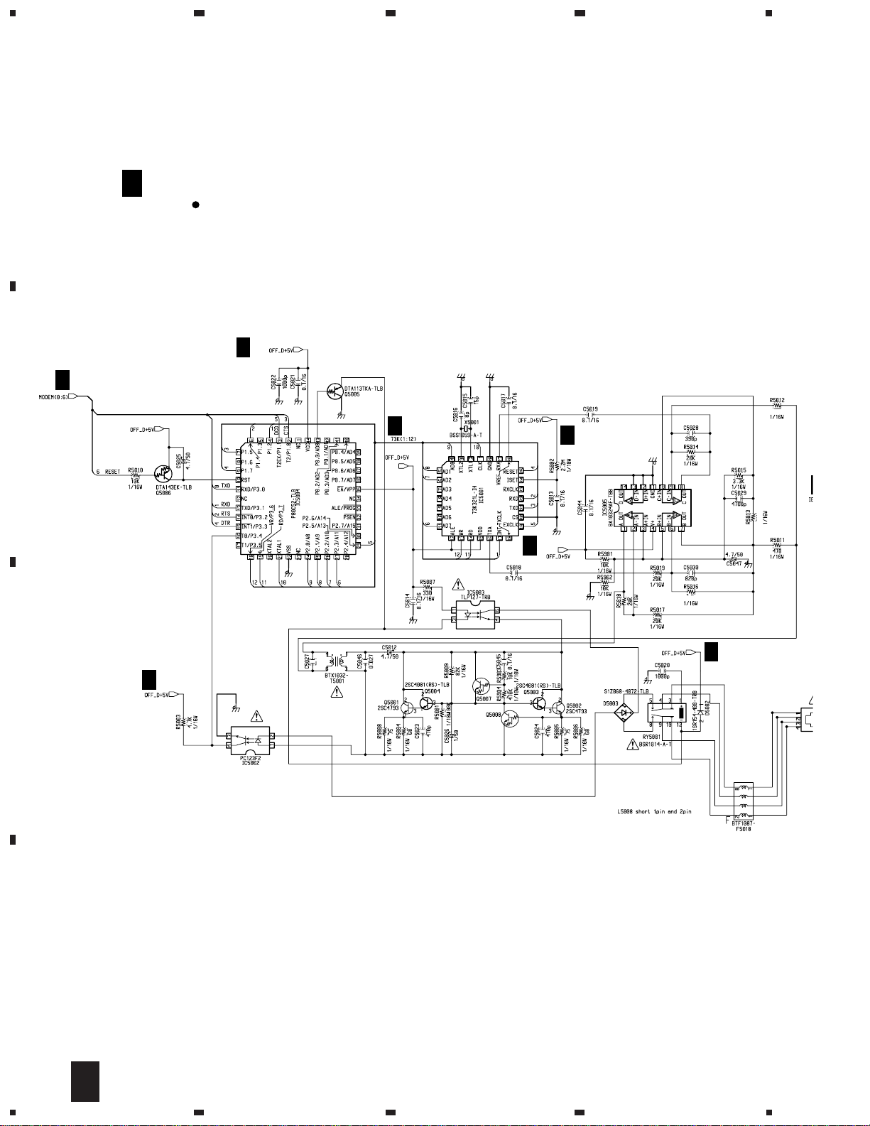
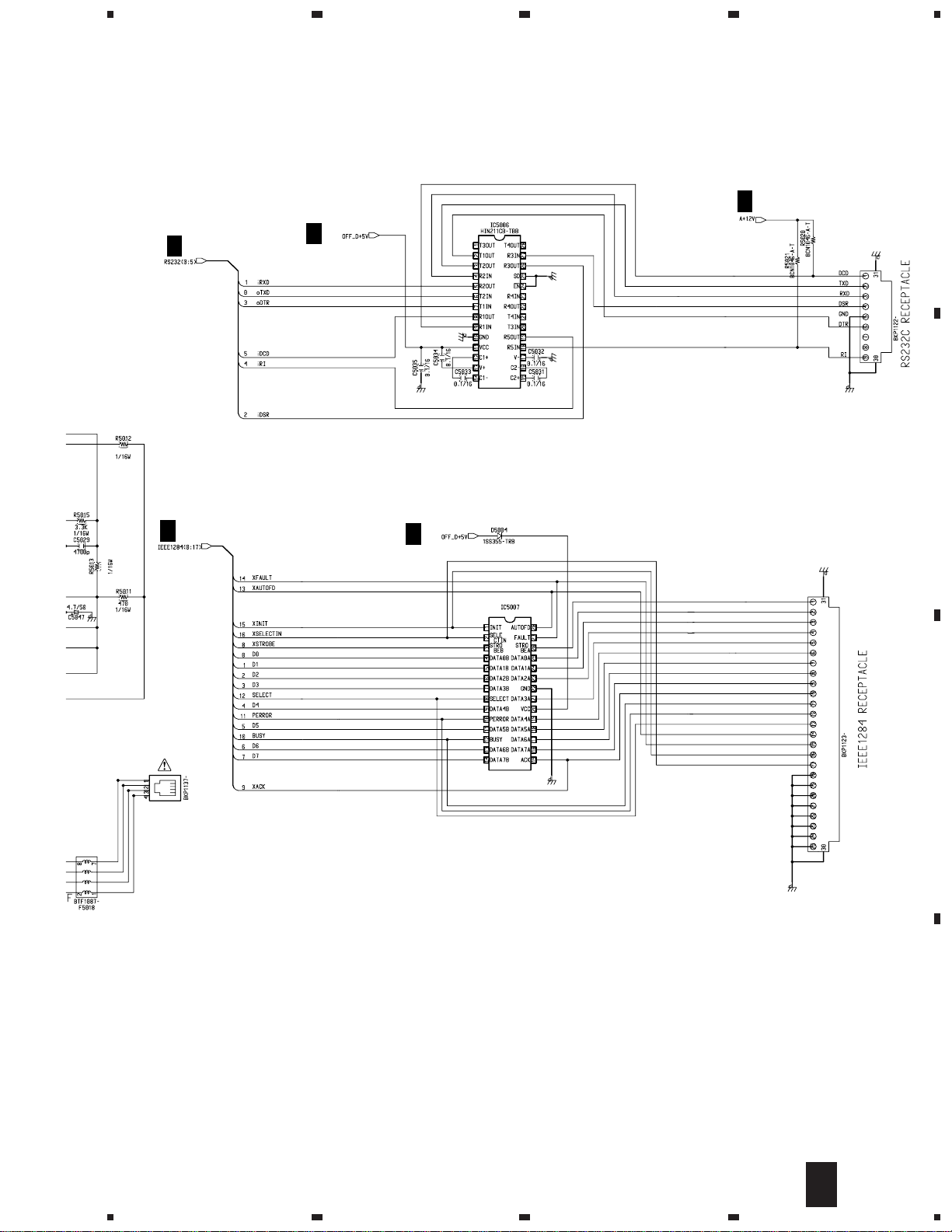
3.7 MAIN ASSY(5/6)
A
A 5/6
MAIN ASSY (5/6) (BWE1055)
I/O MODEM BLOCK
IC5004 : MODEM U-COM
A
6/6
A
2/6
B
IC5001 : MODEM IC
A
6/6
-TLB
A
6/6
A
20K
6/6
20K
15K
A
0.033
A
6/6
C
D
2SC4061K(NP)-TLB
MMSTA13-TLB
LB
6/6
MO
16
5/6
A
1234
5
678
TS4
20K
20K
A
A
2/6
2/6
A
6/6
IC5006 : RS-232C DRIVER
A
6/6
PACS1284-04Q
A
A
6/6
SERIAL I/F
CN5004
B
/6
CN5003
MODULAR JACK
CN5005
C
IC5007 : Termination Network
PARALLEL I/F
D
5/6
A
5
6
7
8
17
1
TS4
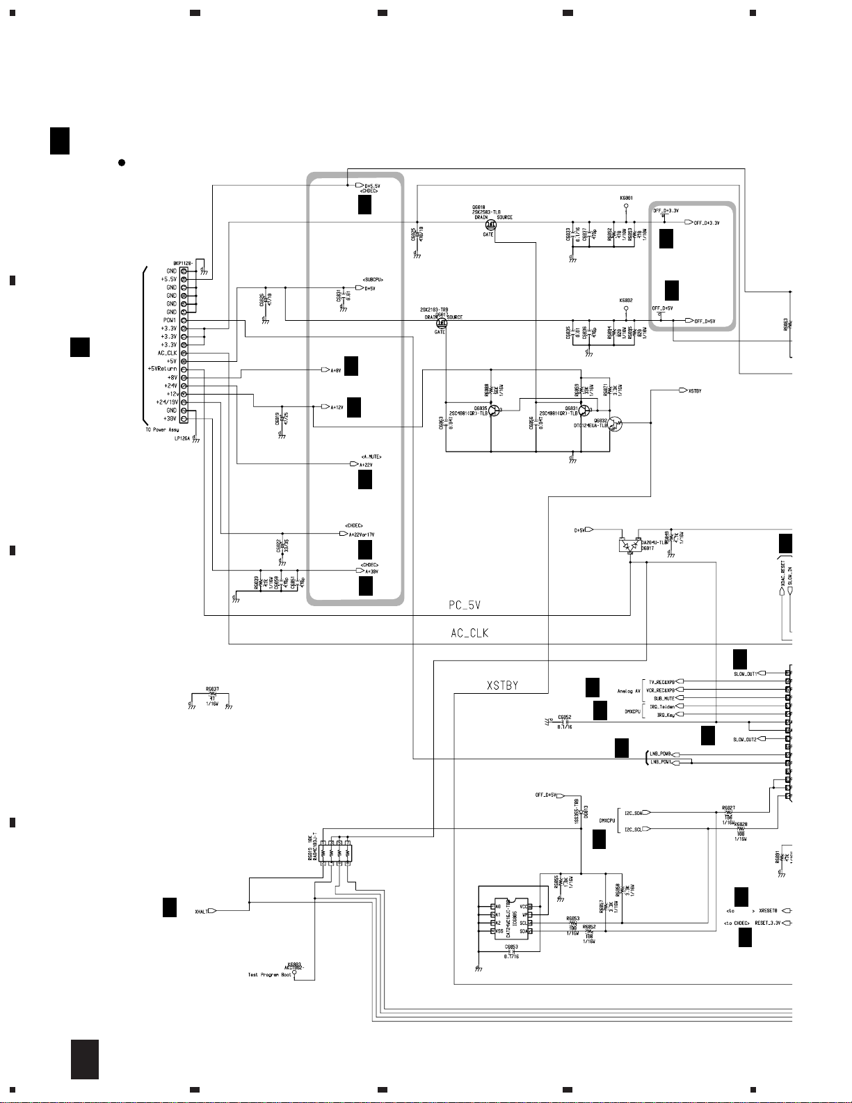
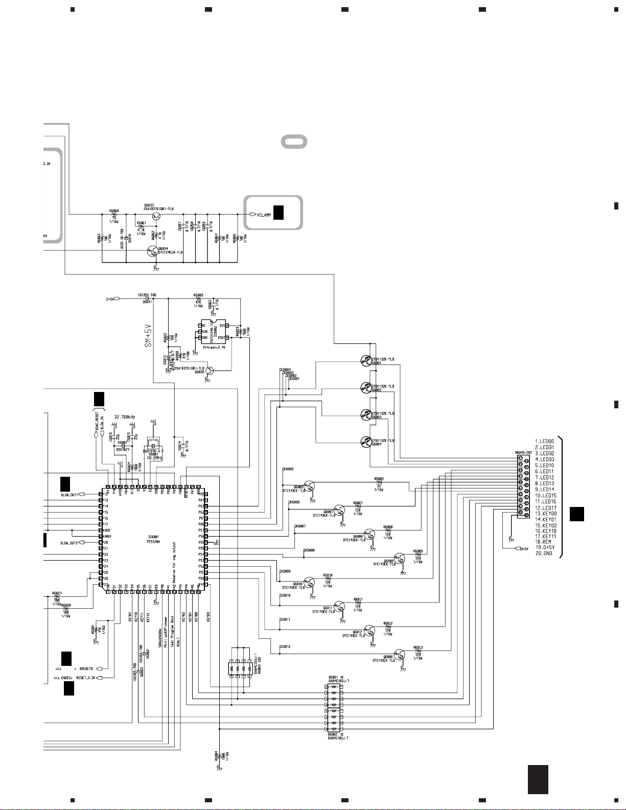
3.8 MAIN ASSY(6/6)
23
4
A
A 6/6
MAIN ASSY (6/6) (BWE1055)
SUBPWR/SUBCPU BLOCK
A 1/6
A 1/6,2/6,3/6
CN6002
A 2/6,4/6,5/6
D
CN201
A 2/6,4/6
B
A 4/6,5/6
A 4/6
A 1/6
A
A 1/6
A 4/6
C
A 4/6
A 2/6
A 4/6
A 1/6
A 2/6
A 3/6
A 2/6
MEMORY
A 1/6
D
IC6005 : EEPROM
18
6/6
A
1234
3/6
,5/6
5
678
TS4
A
: The power supply is shown with the marked box.
A
2/6
IC6002: Reset IC
B
4/6
A
4/6
A
3/6
MEMORY
A
1/6
A
4/6
IC6001 : SUB CPU
CN6001
CN8001
C
B
D
6/6
A
5
6
7
8
19
1
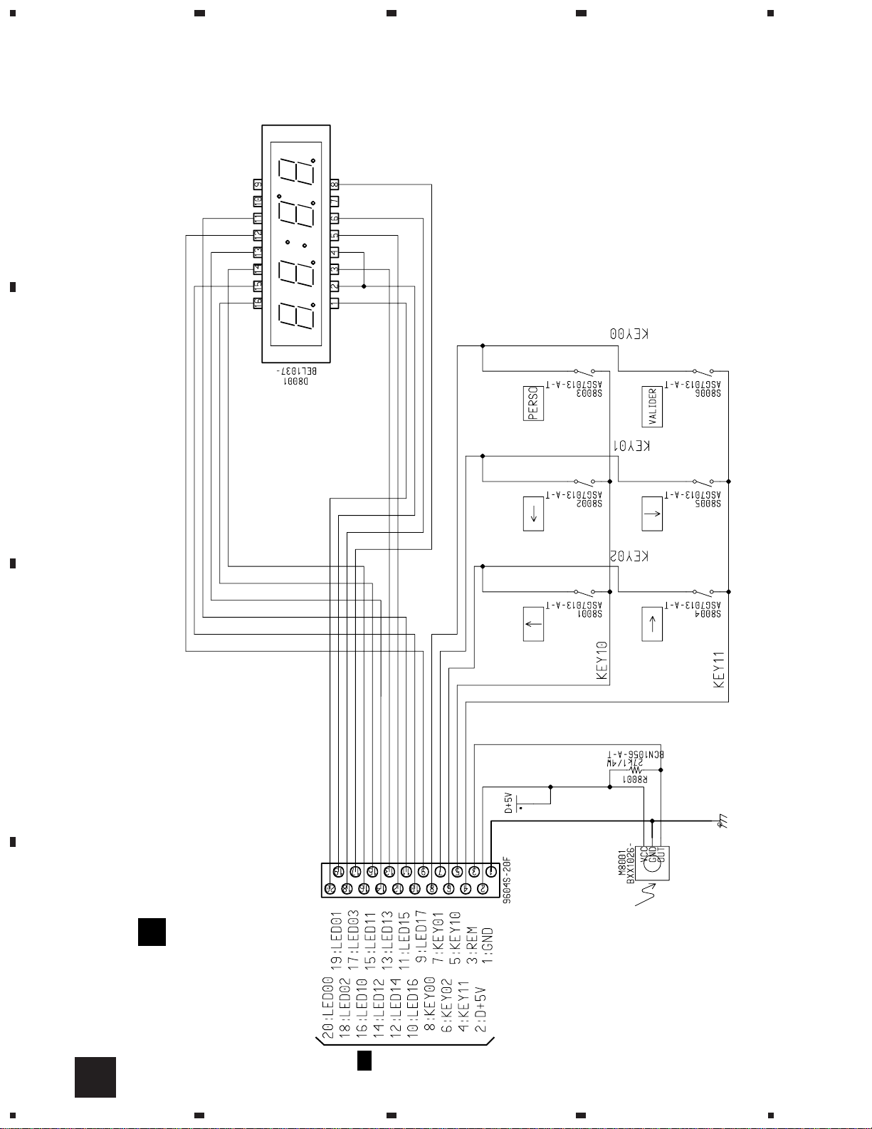
CN8001
SWITCHES
S8001 : ↑ (UP)
S8002 : ← (LEFT)
S8003 : PERSO(MENU)
S8004 : → (RIGHT)
S8005 : ↓ (DOWN)
S8006 : VALIDER(ENTER)
A
6/6
CN6001
FRONT ASSY
(BWE1079)
B
TS4
3.9 FRONT ASSY
A
B
23
4
C
D
B
20
1234
5
CN8502
CN8501
CN8503
A
2/6
CN2003
CARD ASSY
(BWE1080)
C
3.10 CARD ASSY
678
TS4
A
B
C
5
6
7
8
21
C
D
1
TS4
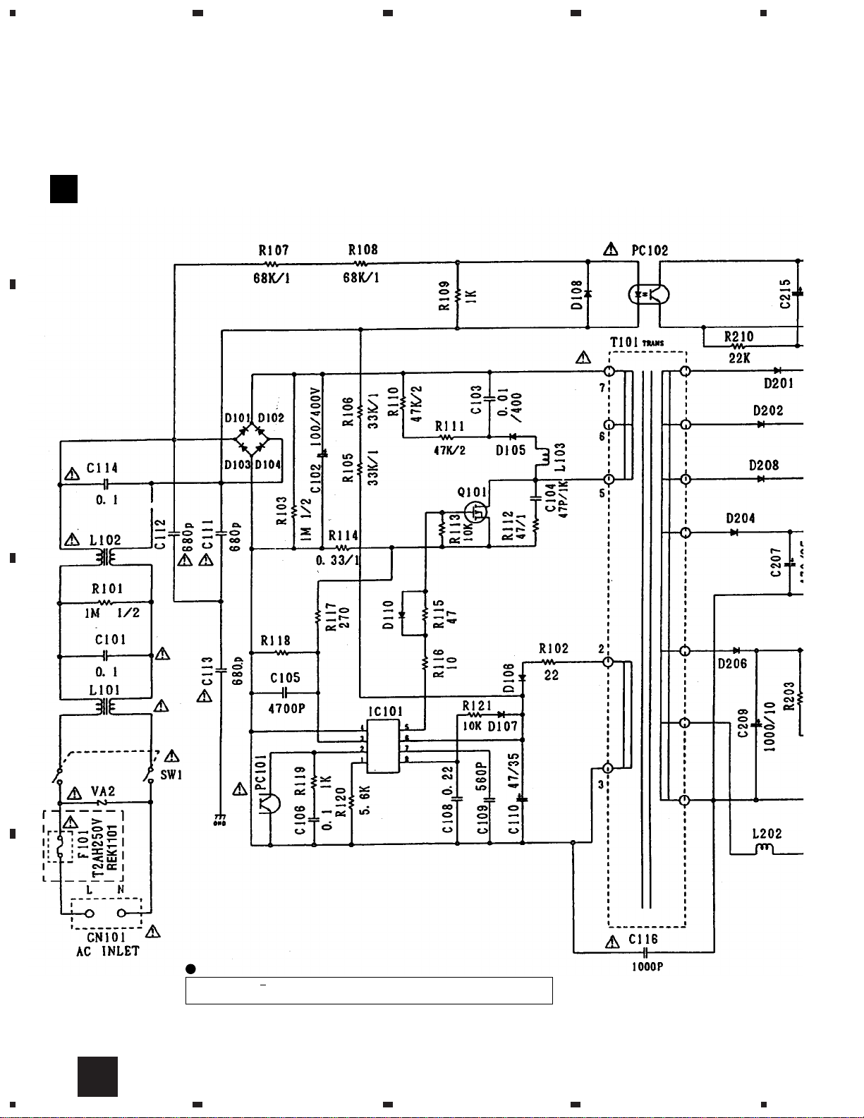
3.11 POWER ASSY
A
POWER ASSY (BXF1112)
D
B
23
4
C
F101 REK1101: Only this part is supplied as a service part..
D
22
D
1234
NOTE FOR FUSE REPLACEMENT
CAUTION
FOR CONTINUED PROTECTION AGAINST RISK OF FIRE.
REPLACE ONLY WITH SAME TYPE AND RATINGS ONLY.
 Loading...