

Page 1
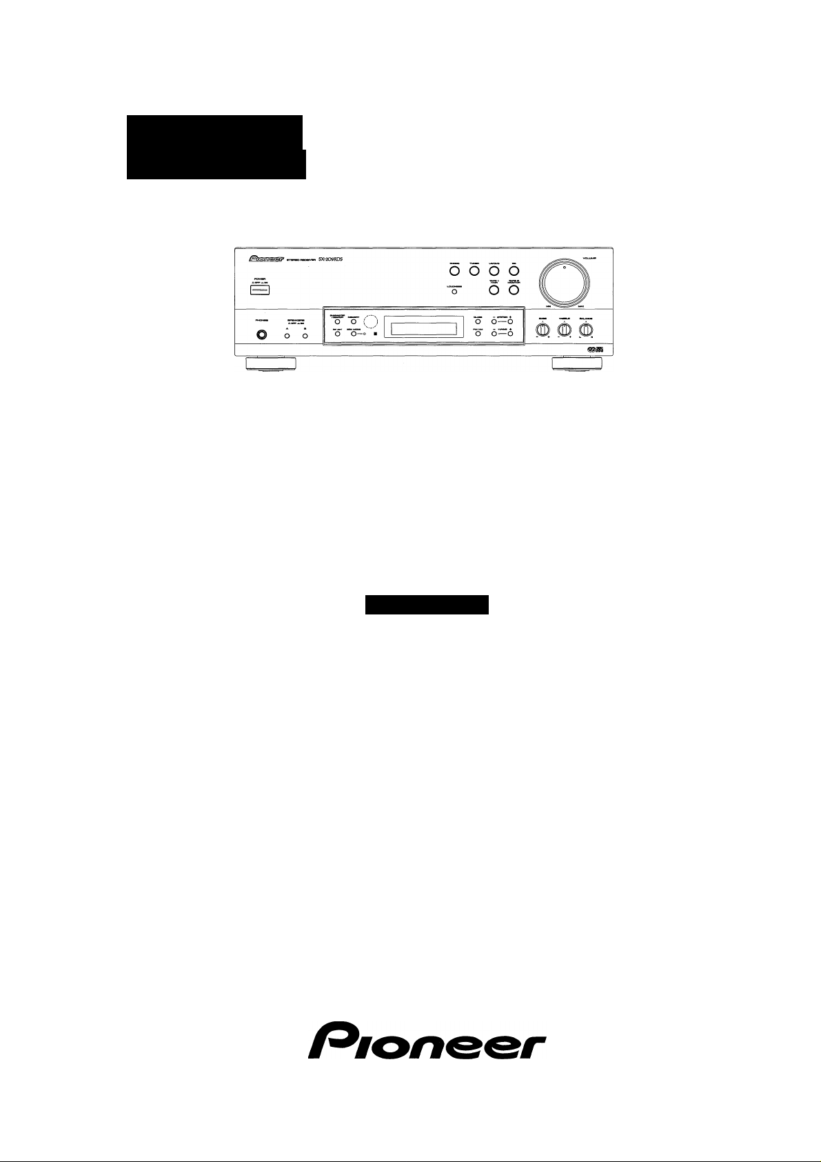
Operating
STEREO RECEIVER
instructions
Thank you for buying this Pioneer product.
Please read through these operating instructions so you will know
howto operate yournnodel properly. After you have finished read
ing the instructions, put them away in a safe place for future ref
erence.
NOTE: Please remove scratch resistant film from the display
window before use.
SX-209RDS
IMPORTANT
CAUTION
RISK OF ELECTRIC SHOCK
A
The lightning flash with arrowhead, within an
equilateral triangle, is intended to alert the user to the
presence of uninsulated "dangerous voltage" within the
product's enclosure that may be of sufficient
magnitude to constitute a risk of electric shock to
persons.
CAUTION:
TO PREVENT THE RISK OF ELECTRIC SHOCK, DO
NOT REMOVE COVER (OR BACK). NO USERSERVICEABLE PARTS INSIDE. REFER SERVICING TO
QUALIFIED SERVICE PERSONNEL.
DO NOT OPEN
WARNING : TO PREVENT FIRE OR SHOCK HAZ
ARD, DO NOT EXPOSE THIS APPLIANCE TO RAIN
OR MOISTURE.
This product complies with the Low Voltage Directive (73/23/
EEC), EMC Directives (89/336/EEC, 92/31/EEC) and CE Marking
Directive (93/68/EEC).
A
The exclamation point within an equilateral triangle is
intended to alert the user to the presence of important
operating and maintenance (servicing) instructions in
the literature accompanying the appliance.
The cut-off plug should be disposed of and must not be
IMPORTANT
FOR USE IN THE UNITED
KINGDOM
The wires in this mains lead are coloured in
accordance with the following code :
If the plug provided is unsuitable for your socket
outlets, the plug must be cut off and a suitable plug
fitted.
Blue : Neutral
Brown : Live
inserted into any 13 amp socket as this can result in electric
shock. The plug or adaptor or the distribution panel should
be provided with 5 amp fuse. As the colours of the wires in
the mains lead of this appliance may not correspond with
coloured markings identifying the terminals in your plug,
proceed as follows :
The wire which is coloured blue must be connected to the
terminal which is marked with the letter N or coloured black.
The wire which is coloured brown must be connected
to the terminal which is marked with the letter L or coloured
red.
CONTENTS
CHECKING ACCESSORY ITEMS
INSTALLATION........................................................................... 2
CONNECTIONS.......................................................................... 3
REAR PANEL FACILITIES......................................................... 5
FRONT PANEL FACILITIES....................................................... 6
REMOTE CONTROL UNIT FACILITIES
SETTING THE UNIT PRIOR TO OPERATION.......................... 9
LISTENING TO A BROADCAST................................................ 9
.............................................
....................................
Do not connect either wire to the earth terminal of a
three pin plug.
NOTE
After replacing or changing a fuse, the fuse cover in the
plug must be replaced with a fuse cover which corre
sponds to the colour of the insert in the base of the plug
orthe word that is embossed on the base of the plug, and
the appliance must not be used without a fuse cover. If
lost replacement fuse covers can be obtained from;
your dealer.
Only 5 A fuses approved by B.S.I. or A.S.T.A to B.S.
1362 should be used.
2
8
DIRECT ACCESS TUNING
PRESET TUNING..................................................................... 11
RDS (Radio Data System) BROADCAST
RECEPTION.............................................................................. 12
TO LISTEN TO OTHER MUSIC SOURCES............................. 18
TAPE RECORDING................................................................... 18
TROUBLESHOOTING............................................................... 19
SPECIFICATIONS......................................................................20
.....................................................
10
Page 2
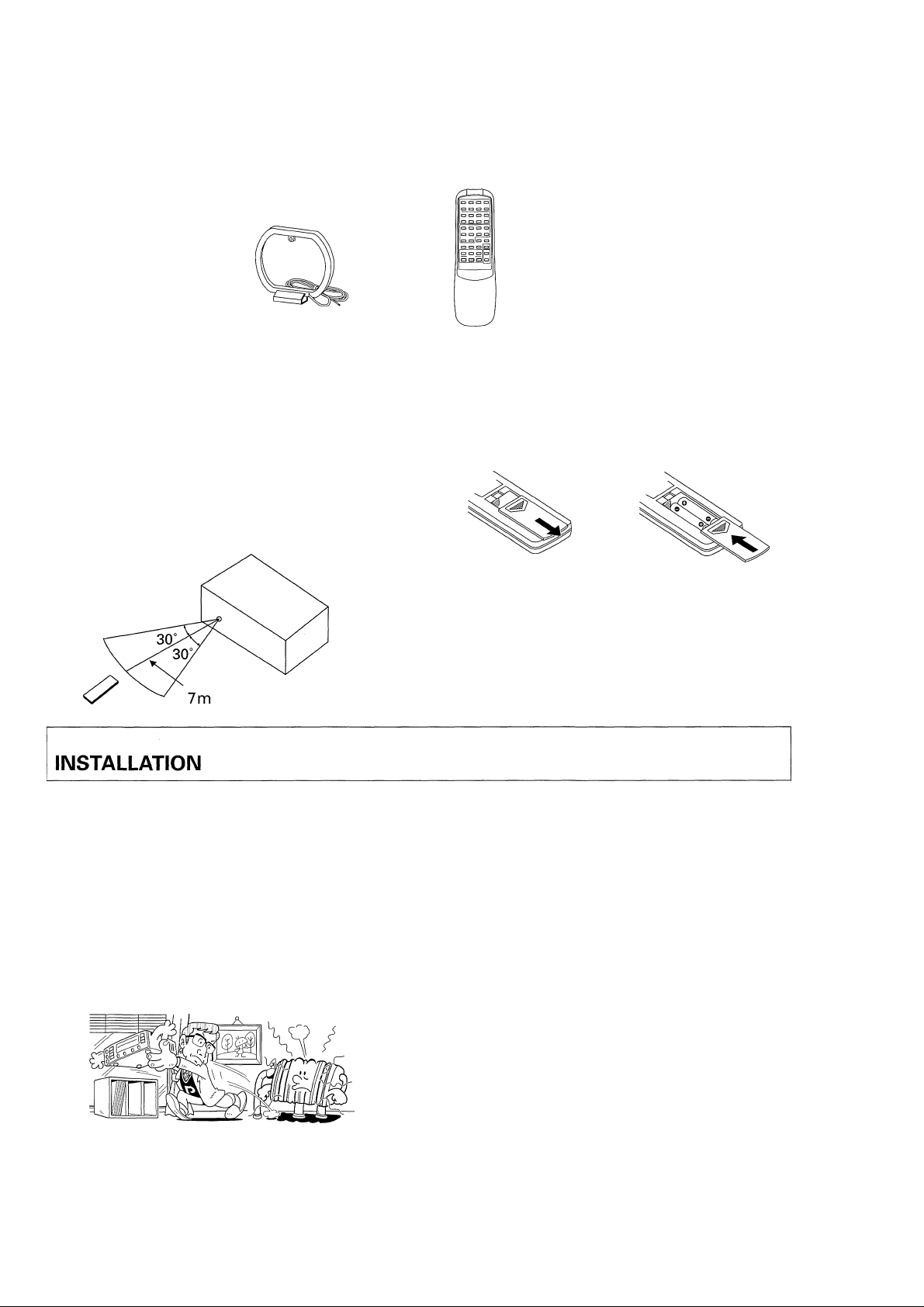
FM Antenna
AM Loop Antenna
Remote control unit Dry cell batteries (AA/R6P)
REMOTE CONTROL RANGE
When operating the remote control unit, point the front of the
unit at the front panel of the receiver. The remote control unit
may be used within a range of about 7 meters from the remote
sensor, within angles of up to about 30 degrees.
Remote control will not be possible if there is an obstacle be
tween the remote control unit itself and the remote sensor win
dow in the receiver. Performance of the remote control unit is
adversely affected in the presence of strong fluorescent light. Keep
such lights away, especially from the sensor window.
LOCATION
Install the unit in a well-ventilated location where it will not
be exposed to high temperatures or humidity.
Do not install the unit in a location which is exposed to direct
rays of the sun, or near hot appliances or radiators. Excessive
heat can adversely affect the cabinet and internal components.
Installation of the unit in a damp or dusty environment may also
result in a malfunction or an accident. (Avoid installation near
cookers etc., where the unit may be exposed to oily smoke, steam
or heat.)
Do not install the unit on a tottered stand, nor on an unstable or
inclined surface.
LOADING BATTERIES
1. Open the rear cover.
2. Install AA/R6P batteries correctly matching polarities.
3. Close the cover.
Incorrect use of batteries may lead to leakage or rupture.
Always be sure to follow these guidelines:
A: Always insert batteries into the battery compartment correctly
matching the positive (+) and negative (-) polarities, as indi
cated inside the compartment.
B: Never mix new and used batteries.
C: Batteries of the same size may have different voltages, de
pending on their type. Do not mix different types of batteries.
POWER-CORD CAUTION
Handle the power cord by the plug. Do not pull out the plug by
tugging the cord and never touch the power cord when your hands
are wet as this could cause a short circuit or electric shock. Do
not place the unit, a piece of furniture, etc., on the power cord, or
pinch the cord. Never make a knot in the cord or tie it with other
cords. The power cords should be routed such that they are not
likely to be stepped on. A damaged power cord can cause a fire
or give you an electrical shock. Check the power cord once in a
while. When you find it damaged, ask your nearest PIONEER au
thorized service center or your dealer for a replacement.
VENTILATION
2
<XRB1008>
Do not install this product into the rack because the MAIN
POWER switch is on the rear panel.
When installing this unit, make sure to leave space around the
unit for ventilation to improve heat radiation (at least 55 cm at
top, 10 cm at rear, and 20 cm at each side). If not enough space
is provided between the unit and walls or other equipment,
heat will build up inside, interfering with performance or
causing malfunctions.
Do not place on a thick carpet, bed, sofa or fabric having a
thick pile. Do not cover with fabric or other covering.
Anything that blocks ventilation will cause internal tempera
ture to rise, which may lead to breakdown or fire hazard.
Page 3
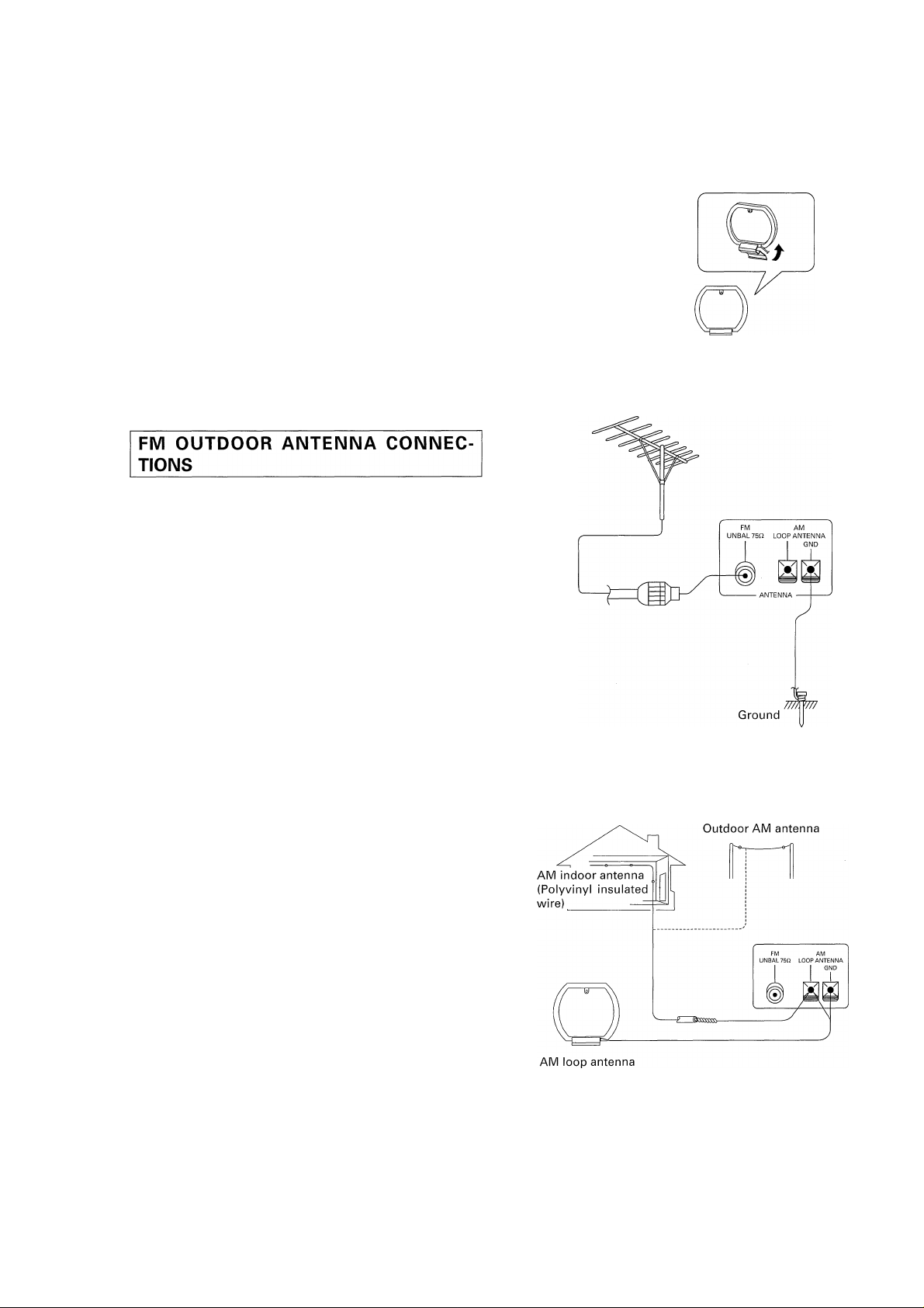
Setting up the AM antenna
• Insert the claw on the bottonn of the antenna into the groove
in the leg.
• Place the antenna on a level surface and rotate it to locate the
orientation that yields the best reception.
• To permanently fix the antenna, screw the leg to a wall or other
similar surface before assembling (fixing the antenna in the
direction that gives the best reception).
EXTERNAL FM ANTENNA
The main advantage of FM over AM is the quality of the broad
cast signal. In order to benefit fully from the high signal quality of
FM broadcasts, it is recommended that a special-purpose FM
antenna be installed. In weak signal areas, a multi-element (3element, 5-element, 7-element, etc.) antenna should be used.
If an FM antenna has already been erected outdoors, connect it,
referring to the figure.
GROUNDING
Grounding is recommended if reception of FM programs is im
paired by noise. To ground, connect a thick polyvinyl insulated
wire to the GND terminal and attach the other end to a metal
water pipe or grounding bar or wind it around a copper plate and
bury it.
NOTE:
Never connect a wire to a gas pipe for grounding since sparks
may ignite the gas.
Connecting the coaxial cable
FM antenna
EXTERNAL AM ANTENNA
If it is not possible to obtain adequate AM reception even by
changing the orientation of the AM loop antenna, a separate in
door antenna, or an outdoor antenna should be installed.
INDOOR AM ANTENNA
Use a polyvinyl insulated wire (5 — 6 m) and connect one end to
the AM antenna terminal and affix the other end to a wall or ceil
ing, as high as possible.
OUTDOOR AM ANTENNA
If reception quality is not improved sufficiently even when an
indoor antenna is used, a polyvinyl insulated wire should be in
stalled outside and fixed in place.
NOTE:
Do not detach the AM loop antenna when using an indoor or an
outdoor AM antenna.
<XRB1008>
3
Page 4
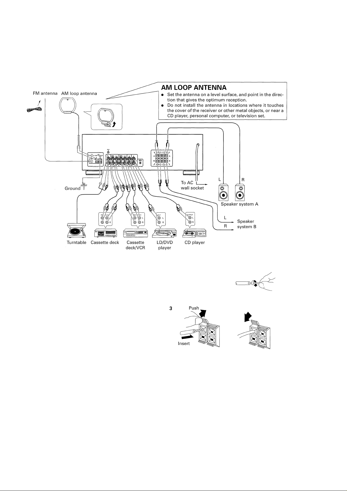
CONNECTIONS
• Before making or changing the connections, switch off the power switch and disconnect the power cord from the AC outlet.
Connecting the input/output cords
When another stereo component (purchased separately) is con
nected, note the following instructions:
• Connect the plugs properly. Faulty connections can cause noise
and also breakdowns and failures.
• The white terminal is for the left channel and the red terminal
is for the right channel.
Connecting the speaker cords
1 2
Speaker cord
Cutter
Twist the strands
Pull
NOTES ABOUT SPEAKER CONNECTIONS
When connecting to only speakers A or speakers B, use
speakers with a nominal impedance of between 4iTand 16
Q.
If you connect to both speakers A and B, use speakers with
a nominal impedance between 8 H and 32 Q.
Be sure that connections are secure. Check to make sure
that wires do not protrude from their terminals.
Do not allow the speaker cords to become short-circuited.
Damage may result to your unit.
Do not attempt to connect two sets of speakers to a single
side (A or B). When using two sets of speakers, connect
one set to terminals A and the other set to terminals B.
4
<XRB1008>
Page 5
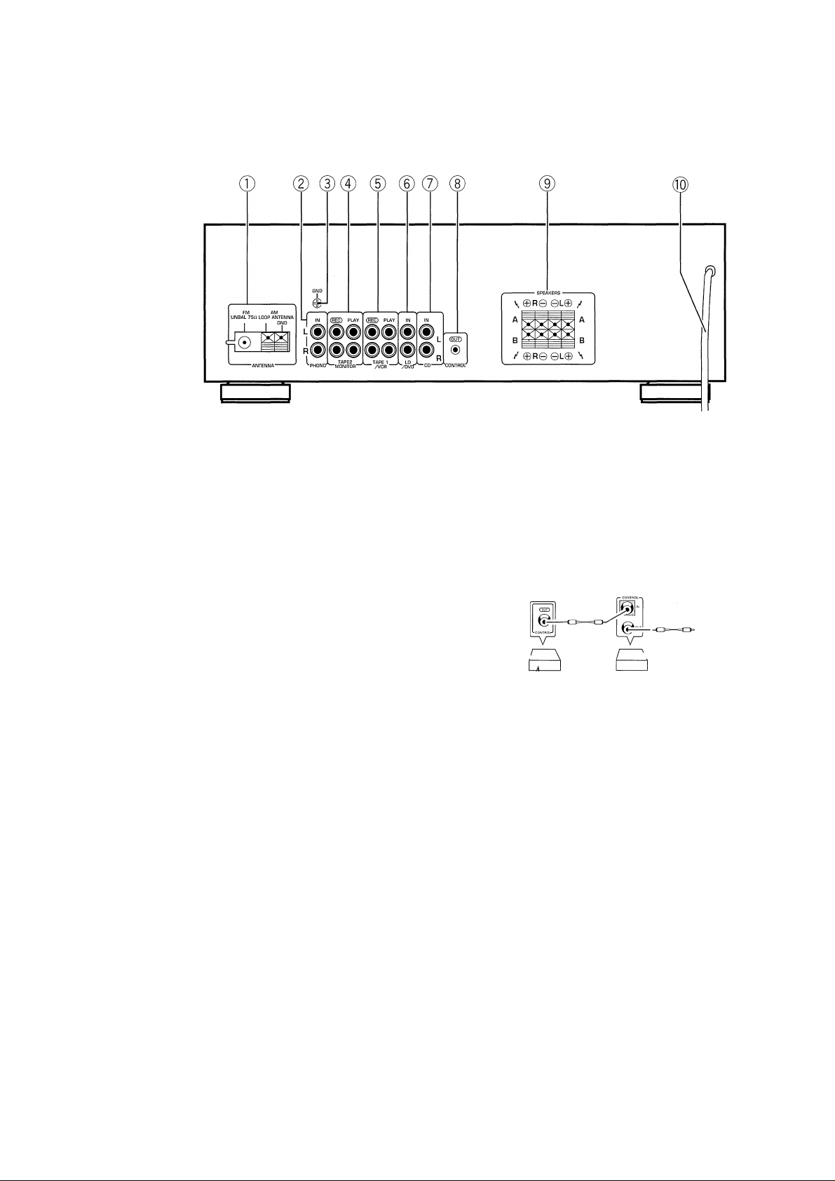
REAR PANEL FACILITIES
® FM/AM ANTENNA terminals
©PHONO jacks
Connect to the output cables from a turntable.
(DGND terminal
Connect to the ground lead of a turntable.
Use a screwdriver to connect with the ground terminal.
NOTE:
This is used to decrease noise and does not serve as a complete
ground.
©TAPE 2 MONITOR jacks
Connect these jacks to the cassette deck.
©TAPE 1/VCR jacks
Connect these jacks to the cassette deck or video cassette recorder.
©LD/DVD jacks
® CD input jacks
©CONTROL OUT jacks
Connects this jack to the control input jack of an unit attached HI
mark using a commercially available cord with mini-plugs (with
out load).
Outputs the remote control signal to another unit from this unit
or the relay signal from the control input jack.
To the CONTROL
IN jack of other
component.
Receiver
Pioneer component
bearing the ^ mark.
Remote control
unit
©SPEAKERS terminals
A; Connect to a first set of speakers.
B; Connect to a second set of speakers.
) Power cord
<XRB1008>
Page 6
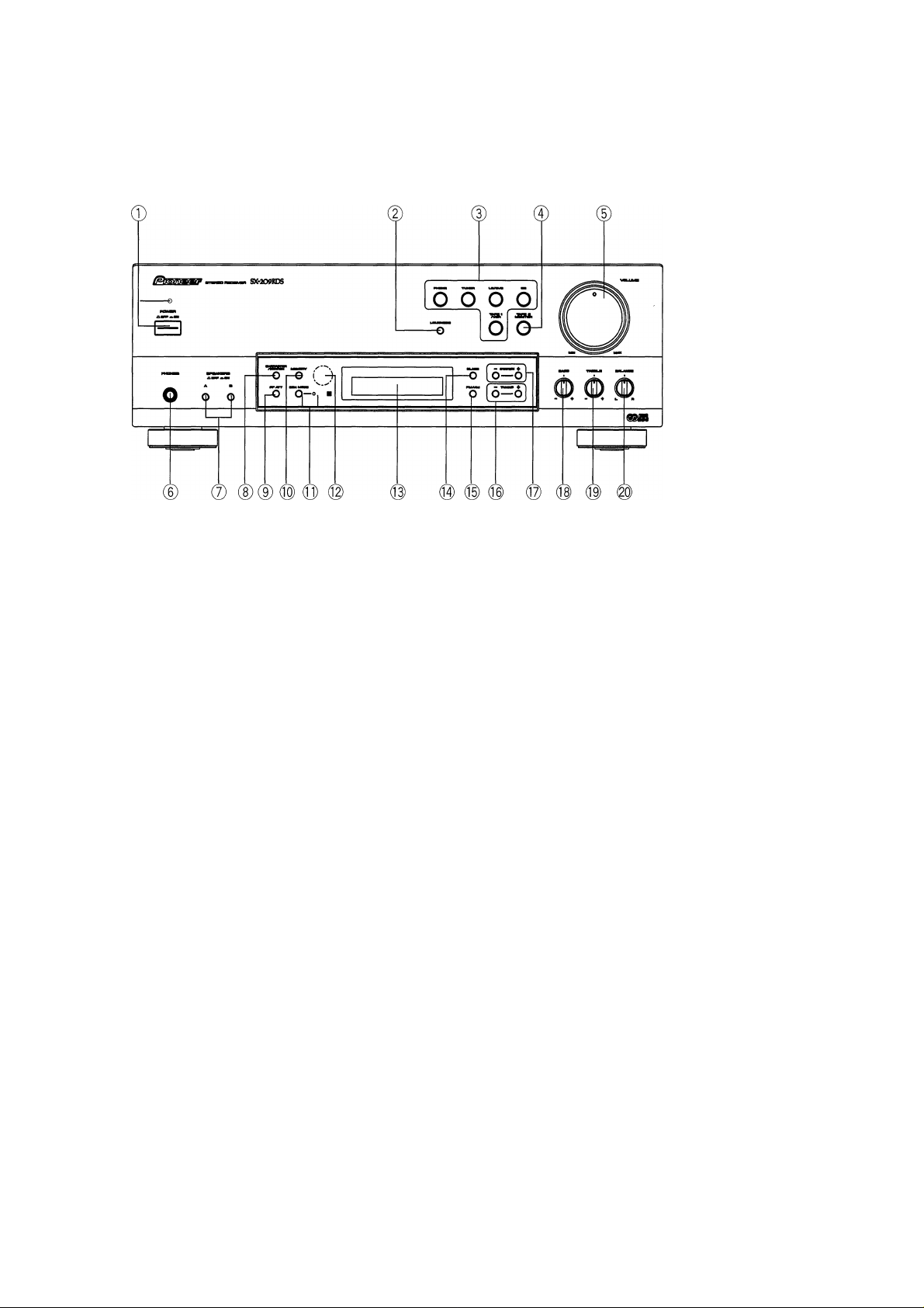
® POWER switch/STANDBY indicator
This is the switch for electric power,
©VOLUME control
Use to adjust the volume level.
ON: When set to the ON position, power is supplied and
the unit becomes operational.
OFF: When set to the OFF position, no power is supplied
to the unit.
(REMOTE CONTROL ONLY)
STANDBY: When set to the STANDBY position, the STANDBY
indicator lights and the main power flow is cut so the
unit is no longer fully operational.
A minute flow of power feeds the unit to maintain
operation readiness.
NOTE:
When the power is initially turned ON, muting will be applied to
prevent sound from being output for approx. 5 seconds.
©LOUDNESS button
Use when listening at low volume levels.
ON: Boosts low and high frequencies to produce a fuller sense
of sound, particularly at low volume levels.
OFF: Normal position.
NOTE:
Cannot be used when the DIRECT function is ON.
The DIRECT function can be turned ON/OFF using the remote
control unit.
@ Function buttons
Use to select playback source.
[PHONO] — Press when listening to record playback on a turn ta
ble.
[TUNER] — Press when listening to AM or FM broadcasts with a
tuner.
[LD/DVD] — Press when listening to LaserDiscs played back from
a LD player or Digital Video Discs played back from
a DVD player.
[CD] — Press when listening to compact disc playback with a
CD player.
[TAPE 1 A/CR] — Press when listening to tape playback with cas
sette deck 1 or a video cassette recorder.
©PHONES jack
Connect the plug on your headphones to this jack. To listen to a
program through the headphones, set both SPEAKERS A and B
switches to the OFF position.
©SPEAKERS (■ OFF, ON) buttons
These are used to select the speaker through which you wish to
listen.
A: When the speakers connected to the A terminals are in use.
B: When the speakers connected to the B terminals are in use.
• Turn both A and B speakers to the OFF position when only
headphones are in use.
©CHARACTER/SEARCH button
When receiving an AM broadcast, or when in the FM RT, FM PS
modes:
Press the button, 'INPUT" is displayed, and the mode switches
to manual station name input.
When in the FM PTY mode:
Press the button, "SEARCH" is displayed, and the mode switches
to program type search.
• This button does not function when the frequency is displayed
(FM broadcast only).
© RF ATT button
Set this button to ON when receiving strong FM signals (near-by
stations) to reduce sound distortion. (RF ATT indicator lights.)
Normally, this button should be set to OFF.
This button has no effect on reception of AM broadcasts.
©MEMORY button
Pressing this button will result in the memorization of the current
broadcast band, reception frequency, RF ATT (FM reception only)
and FM AUTO/MONO mode.
This button is also used to select characters during station name
entry and to clear memory during ERASE PI operation.
®TAPE 2 MONITOR button
Press when listening to tape playback with cassette deck 2.
6
<XRB1008>
Page 7

FRONT PANEL FACILITIES
D)EON (Enhanced Other Network information)
MODE button/indicator
See page 15.
l|) Remote sensor
¡3) OPERATION DISPLAY panel
(a) (b) (c) (d) (e)(f)(g)
I DIRECT I LOUDNESS
lonoff-i
....
.......................................................................
AM IVI IWI IVI IWI IVI IVI )r7 IVI
™ IKI lAI IKI. lAJ lAJ IKI IKI IK\
(k)
DIRECT ON/OFF indicator
(a)
(b)
LOUDNESS indicator
TAPE 2 monitor indicator.
(c)
CLASS indicator
(d)
MONO indicator
(e)
Lights up when a stereo FM broadcast is being received.
(f)
Lights up when a station is tuned.
(g)
RF ATT indicator
(h)
Lights when an RDS broadcast is received.
(i)
Lights when a station broadcasting EON information is re
(j)
ceived.
Frequency, function, character display
(k)
MEMORY indicator
(l)
(m) Channel display
MEMORY RDS-
I o
I LI ch
I
___^__
(I) (m)
EON -
©STATION buttons (- +)
+: Stations change in order in the upward direction.
Stations change in order in the downward direction.
® BASS tone control
Use to adjust low-frequency tones. The center position is the flat
(normal) position. When turned to the right, low-frequency tones
are emphasized.
NOTE:
This control can not be used when the DIRECT function is ON.
-(h)
The DIRECT function can be turned ON/OFF using the remote
control unit.
-(i)
(i)
I
©TREBLE tone control
Use to adjust high-frequency tones. The center position is the
flat (normal) position. When turned to the right, high-frequency
tones are emphasized.
NOTE:
This control can not be used when the DIRECT function is ON.
The DIRECT function can be turned ON/OFF using the remote
control unit.
® BALANCE control
Should normally be left in the center position. Adjust balance if
the sound is louder from one of the speakers. If the right side is
louder, turn toward the L position and if the left side Is louder,
turn toward the R position.
NOTE:
This control can not be used when the DIRECT function is ON.
The DIRECT function can be turned ON/OFF using the remote
control unit.
® CLASS button
Use to switch between preset memory classes 1 to 3. In each
class, one station can be memorized in each of the 1 to 10 STA
TION CALL buttons, enabling a total of 30 stations to be memo
rized.
©FM/AM selector button
This button is used to select either AM or FM reception.
©TUNING buttons (-, +)
Use for tuning frequencies. Press the buttons to change the fre
quency display (3-speed Accel Tuning) (See page 9).
In the Manual Name input mode and PTY search mode, use to
select characters and program types.
<XRB1008>
Page 8

This remote control unit can be used to operate some functions
of Pioneer HI marked CD players and cassette decks.
®CD operation buttons
BEST: Lets you operate a Pioneer File type CD player
equipped with a Best selection memory function.
■: Stop
II: Pause
►: Play
Track search.
DISC - +: DISC selection.
NOTES:
• Note that the DISC -+ buttons on the accessory remote con
trol unit may not function, depending on the CD player used.
• Refer to your CD player's operating instructions for details.
©TAPE operation buttons
DECK I: DECK I selection.
DECK II: DECK II selection.
►: Reverse and Forward playback.
(Set the TAPE function button.)
Rewind in forward mode, fast forward in reverse
mode.
Fast Forward in forward mode, rewind in reverse
mode.
■: Stop
II: Pause
NOTES:
• To operate a double cassette deck, first press the Deck I or
Deck II button to select the desired deck. Then press the cor
rect control buttons.
• To operate a single deck, first press the Deck II button. Then
press the correct control buttons.
• Refer to your cassette deck's operating instructions for details.
©Station call buttons
These buttons are used to recall desired broadcasting stations
and direct access tuning.
® FM/AM button
To select either FM or AM broadcasts.
® MPX MODE selector button
Use to select the auto stereo mode or monaural mode when lis
tening to FM broadcasts. The monaural mode has been selected
when the FM MONO indicator is lit.
This button's status is preset for each station in station memory.
Auto stereo mode;
Normally leave in this mode for reception. When a stereo FM
broadcast is received, it will be automatically reproduced in stereo
sound.
Monaural mode;
When receiving distant stations or stations with weak broadcast
signals, the input signal may be weak, thus resulting in increased
noise during FM stereo broadcasts. In this event, setting the re
ceiver to the monaural mode will reduce the noise. In this case,
however, FM stereo broadcasts will be reproduced in monaural
sound.
NOTE:
This button has no effect on reception of AM broadcasts.
©DISPLAY MODE button
Use only during FM reception. Use this to switch between dis
play modes. Each time you press it, the display changes as fol
lows.
^RT mode
I Displays RT ■ ■ PS -► Returns to RT.
PS mode
PTY mode
-----
FREQ (Frequency) mode
©DIRECT button
Use this button when you do not wish to pass the output from
the input terminal through the various frequency adjusting cir
cuits (TREBLE, BASS and LOUDNESS). When this button is on,
the BALANCE control does not operate.
® TAPE 2 MONITOR button
Turns TAPE 2 MONITOR ON/OFF.
@ FUNCTION button
Switches playback components in order.
©RECEIVER POWER button
©CD POWER button
Turns power ON/OFF to the CD player connected to the unit.
©TAPE POWER button
Turns power ON/OFF to the tape deck connected to the unit.
® CLASS button
©DIRECT ACCESS tuning button
When this button is pressed, the STATION CALL buttons function
as ten-key number buttons for direct input of the desired recep
tion frequency. Press again to cancel this mode.
(©MUTING button
Press to temporarily reduce sound. Press again to return to the
original volume level.
©VOLUME +/- buttons
8
<XRB1008>
Page 9

• Before operating the unit, be sure to set it as shown below.
Set the TAPE 2 MONITOR
button to OFF (TAPE 2 Set the VOLUME control to the
indicator goes off). "MIN" position.
. Set the BALANCE control
to the center position.
MANUAL (FM/AM)/AUTO (FM) TUNING
1. Press the TUNER button of the function buttons.
2. Press the FM/AM selector button to select your
desired band.
3. Use the TUNING buttons to locate the frequency
of the desired station.
<3-speed accel tuning>
[Manual tuning]
Press the TUNING button and release it quickly. The frequency
will change by one step each time the button is pressed. Press as
many times as necessary to tune in the desired station.
Steps change in the following way; FM: 50 kFIz, AM: 9 khlz.
[Auto tuning (FM)]
Press the TUNING button until the frequency starts to change,
then release it. The tuner will automatically search for a broad
casting station and stop when one is found.
To search for another station, press again.
[High speed manual tuning]
Keep the TUNING button pressed. The frequency changes con
tinuously, and stops when the button is released.
NOTE:
The TUNED indicator will not function for broadcasts received
over long distances or when signals are weak.
2 3
When Receiving FM Broadcasts:
• If there is distortion because the radio signal is too strong,
press the RF attenuator (RF ATT) button to light the RF ATT
indicator (FM reception only).
• If there is too much noise during reception of an FM stereo
broadcast, press the MPX button to light the MONO indicator.
Switching to monaural reception results in clear reception.
Note about Auto Tuning
• Because of the high sensitivity of this unit, it may automati
cally stop even at very weak overseas stations. The same can
happen with aggregate radio noise emitted in cities.
• Preset extremely weak stations with manual tuning.
The TUNED Indicator
When the TUNED indicator is not lit, reception is not possible
even if the tuning frequency is correct. This is because the an
tenna terminal input is too weak. Check whether the antenna ca
ble is firmly connected. If it is, consult your nearest dealer and
install an outdoor antenna.
<XRB1008>
9
Page 10

DIRECT ACCESS TUNING
LISTENING TO BROADCASTS USING DIRECT ACCESS TUNING
When you know the frequency of the desired station, the fre
quency can be input directly using the station call (number) but
tons in the following way:
FM
1. Press the POWER switch to the ON position.
NOTE:
Be sure to turn the TAPE 2 MONITOR button OFF when listening
to AM or FM broadcasts.
1 LJ b. „
1'// 1
/ 1 r
1
1
Press
2. Select the TUNER function and use the AM/FM
selector to choose either FM or AM.
3. Press the DIRECT ACCESS tuning button.
If you do not perform any operations within five seconds of press
ing the DIRECT ACCESS button, direct access is canceled.
4. Input the desired station frequency using the sta
tion call (number) buttons.
Example 1: To receive FM 106.00 MHz
niRECT
^DIHECTJ
. „ II I"
^DIRECTJ
/
FM / M ^
FM j
. „ II r 1
i n
' LJ IV. - . „ / f /■■ 1
1'// 1
1'// 1
1'// 1
1
■f
Press the DIRECT ACCESS
tuning button.
J ”
/
ACCESS
1 il
Press the 1 button
Press the 0 button
FM
/ n IV n
1 LJ LJ. LJ IV
1 1 r
1
/
1
Press the 0 button twice
To cancel frequency input
Direct access is canceled when the DIRECT ACCESS tuning but
ton is pressed again.
Under the following conditions direct access is canceled:
® If there is no key input for about five seconds after the DIRECT
ACCESS tuning button was pressed.
(2) If more than about five seconds elapse between number in
put.
10
<XRB1008>
Page 11

FREQUENCY PRESETTING
10 stations can be preset in each of the 3 classes, for a total of 30
station-presets.
CLASS 1 = 1 to lOch
CLASS 2 = 1 to 10 ch
CLASS 3 = 1 to 10 ch
Example:
Presetting an FM 106.00 MFIz station into class 2 with station No.
(CH) 1.
MEMORY
/ n r f
™ 1 LJ LJ. L
/
FM 1
'7 n !>// I.l V
J LJ / 1 / / i. 0 oh
n 1” r
1 n )'// I / ” “7°""
LJ LJ. LJ LJ 1 1 r 1 -0 ch
[Ci^sr>i^- TUNED
|CLftSS> ^(i]3 TUNED
42 3
1. Press the POWER switch to the ON position.
NOTE:
Be sure to turn the TAPE 2 MONITOR button OFF when listening
to AM or FM broadcasts.
2. Press the TUNER button and set the FM/AM se
lector to either FM or AM.
3. Tune in the desired station.
• See the section “DIRECT ACCESS TUNING" for information
on reception using the Direct Access Tuning mode.
• See the section "MANUAL/AUTO TUNING" for information
on reception using the Manual tuning mode.
In addition to station frequencies, the MPX MODE (AUTO/
MONO) and RF ATT ON/OFF can also be preset (FM broadcast
only).
4. Press the MEMORY button.
The MEMORY indicator will light.
The figures indicated with "CLASS" and "CFI" flash.
5. Select the desired class (1-3) with the CLASS
button.
6. Select the station number to be memorized by
pressing the STATION +/- buttons or the station
call buttons of the remote control unit.
• Press the STATION +/- buttons while the MEMORY indicator
is lit (about 5 seconds).
7. Repeat steps 2 to 6 to preset additional stations.
• A total of 30 AM and FM stations may be preset. When you
store a new preset, it takes the place of the previously stored
station (if any).
• If you press the CLASS button while the MEMORY indicator is
not lit, the CLASS and frequency indication values will change.
Pressing the STATION +/- buttons at this time will memorize
the station at a station number in the chosen CLASS.
■ STATION H
/ n r i
FM
1 LJ LJ. LJ LJ 1 1 n
'7 n /'// 1 / ”
i£^M> E
TUNED
1
f ch
PRESET STATION TUNING
1. Select the class number with the CLASS button.
2. Select the desired station number to recall by
pressing STATION +/- button.
You can also recall stations using the station call buttons (1-0/
10) on the remote control unit.
NOTES:
• The contents of preset memory will be preserved for several
days, even if the receiver's power cord is unplugged.
• If a preset station has been erased, preset it again.
Last station memory
When the POWER switch is pressed to turn the power on, the last
station received before the power was turned off will be received
again.
11
<XRB1008>
Page 12

What is RDS (Radio Data System)
In the RDS system, FM broadcast stations transmit such informa
tion as station name and program type in addition to audio sig
nals. This unit receives and displays the following three kinds of
data.
RT (Radio Text) data
A message transmitted from the broadcast station using a maxi
mum of 64 characters.
PS (Program Service Name) data
This refers to the broadcast station name transmitted by an FM
broadcast station.
PTY (Program Type) data
During reception of an FM program, this data indicates the type
of program.
The following are the 15 PTY data titles transmitted.
News:
I' / i:: 11 r
l\l L l/\l „1
Short accounts of facts, events and
publicly expressed views, reportage
and actuality.
Current affairs;
o i::
11 I
c: o
11
O
i\ -j
Topical program enlarging upon the
news. Presentation styles include
documentary, debate and analysis.
Information:
I' I i::
I \i I
n
LI
General information and advice, in
cluding Meteorological Reports/Forecasts. Consumer affairs. Medical help,
Sport:
o n o
-j I LI I \
etc.
Program concerned with any aspect
of Sport.
EON (Enhanced Other Network information)
(see page 15)
EON MODE
When this button is turned on and a memorized traffic informa
tion or NEWS (PTY) station on the FM band broadcasts a pro
gram, it will automatically turn on and interuptthe program that
was being listened to.
This feature can be activated during FM broadcast reception with
the EON indicator lit or during listening to other input function
than TUNER while the tuner's last memory is the FM reception.
TA (Traffic-Announcement identification)
This is an on/off switching signal to indicate whether an announce
ment for motorists is on the air. The signal can be used to auto
matically switch from a program carrying no traffic information
to one carrying a traffic announcement. Normal operating mode
will be restored after the announcement.
PI (Program Identification)
This information consists of a code enabling the tuner to distin
guish between countries or areas in which the same program is
transmitted, and the identification of the program itself. The code
is not intended for direct display and is assigned to each indi
vidual radio program to enable It to be distinguished from all
other programs.
PTY ALARM function
Function which switches to the urgent news broadcast of an FM
station when it is received (PTY data alarm signal). This function
switches even if you are listening to another function. This func
tion is not turned on or off as it is turned on at any time if an FM
news broadcast is memoriezed. During this time, the TAPE 2
MONITOR and MUTING will automatically be off and.the DIS
PLAY mode will be set to PTY.
This state will be maintained even after the PTY data ALARM sig
nal has been canceled.
EON CONTROL
When EON is turned on and a function other than the tuner is set,
the function will switch to the FM station automatically when traffic
information or NEWS starts.
When the program ends, the original function will be set again.
Education:
i:: ri 11 I
L II LI L
" o r c:
.II 1 L
Drama:
ri o i:
"I I'W o
1 11 11
II I \ /
Culture:
r I . I I
LI L
11 o i;:
LI I ^ L
Science:
r; r T c: It I r i::
J L 1 L I L L
Varied:
L o i::i r r Ti
// III
^ 1 L 11
Pop:
0 n o
1 LI 1
Rock:
O n r L
/ ^ LI L / ^
M.O.R.:
li/l
n
0
LI .
1 < .
I I .
Light classics:
I T r: LI
L 1 LI I I
Serious classics:
o »: i:
L L
11 j j
Other music:
n T L
1 c: O
1 L L
LI 1 1 1
r r
1 L
1 (
L/
Program intended primarily to edu
cate, of which the formal element is
fundamental.
All radio plays and serials.
Aspects of National or Regional cul
ture, including Religious affairs. Phi
losophy, Social Science, Language,
Theater, etc.
Programs about the Natural Sciences
and Technology.
Mainly speech-based, light-entertain
ment programs, such as Quizzes,
Panel Games, Personality interviews.
Comedy and Satire.
Commercial music of current popular
appeal, often featuring the current
record sales charts.
Contemporary modern music, usually
1 1
written and performed by young mu
sicians.
(Middle of the Road Music) "Easy-lis
tening" music, often vocal and usu
ally of short duration (< 5 min.).
Classical Music for nonspecialist ap
ll/l
I (
preciation. Examples are instrumen
tal music and choral works.
Performances of major orchestral
works, symphonies, chamber music,
etc., including Grand Opera.
Musical styles other than above cat
li/l
/ 1
egories. For example. Jazz, R & B,
Folk, Country and Reggae.
12
<XRB1008>
Page 13

RDS DATA DISPLAY
2
2
1. Turn on the power and select the TUNER function.
2. Select FM with the FM/AM selector button.
If the received broadcast transmits RDS data, the RDS indicator
lights, and the data of the displayed mode is automatically dis
played in the bottom right of the display.
3. Press the DISPLAY MODE button and the display
changes.
RDS (Radio Data System) BROADCAST RECEPTION
1 DIRECTI
L OFF-*
T
n
i — ch
1 V
|CL&SS>m
STEREO TUNED
RT mode
.........
"RT" flashes and the following data is dis
played in sequence.
RT (Radio Text) scroll display -►PS (Program
Service Name) -►Returns to RT; repeat.
PS mode......... "PS" flashes on the display, and then the
^ broadcast station name is displayed.
PTY mode
......
"PTY" flashes on the display, and then PTY
data is displayed. Indicating the type of
program.
FREQ mode
(Frequency)
NOTES:
• In the RT mode, should any noise be picked up while display
ing the RT scroll, some characters may temporarily be incor
rectly displayed.
• In the RT mode, when no RT data is transmitted from a broad
cast station, "NO RADIO TEXT DATA " is displayed once and
after that the PS data is displayed.
• In the PTY mode during RDS broadcast reception, there are
cases where "NO TYPE" is displayed. In this case, it will auto
matically switch to PS mode after a few seconds (if PS mode
is available.)
• When reception conditions are strong, and RDS data is incor
rectly displayed, press the RF ATT button.
After that, RDS data may be correctly displayed.
• Depending on the broadcast station, numerous program serice
names (PS) may be transmitted in succession. In this case,
when you switch to the RT mode, only some of the PS data
will be displayed, so switch to the PS mode.
• When the RDS indicator is not lit, and you are in the RT mode,
only station names stored in memory manually, if any, will be
displayed.
jDIRECTj
I^DIRECTJ
I^DIRECTJ
r
11JJri 1”
JJ /„
/
Il I
/
r 1
1 1
}j
STEREO TUNED
— ch
♦
fci^ss>m
1" |i//
1
1
/ / (
|CLASS>m
T '/
r.7
1 1
|CLflSS>m
i:: 11
L hi „1
— ch
STEREO TUNED
— ch
STEREO TUNED
— ch
13
<XRB1008>
Page 14

RDS (Radio Data System) BROADCAST RECEPTION
MEMORIZING A DESIRED BROADCAST
STATION NAME (Manual Station Name
Memory)
For each of the 30 preset AM/FM channels, up to four characters
can be mennorized for preferred broadcast station names. Even if
PS data is already received using RDS, an FM broadcast station
name can still be memorized.
In this case, the memorized name takes priority over the PS data
name.
2,6
1. Turn the POWER switch ON and press the TUNER
button.
2. Select the desired broadcast station with the
CLASS button and STATION -/+ buttons.
3. For FM broadcasts, press the DISPLAY MODE
button on the remote control unit to select the
RT mode or PS mode.
4. Press the CHARACTER/SEARCH button.
'INPUT" lights in the display, and the mode switches to manual
station name memory.
5. When "INPUT" is displayed, use the TUNING +/buttons to select a desired character within 5 sec
onds.
® The first character in the display changes each time you press
the TUNING +/- buttons. Select character as desired.
(D When you have selected your character, press the MEMORY
button.
This enters the first character and awaits input of the next
character for memorization.
Repeat this procedure until all four characters have been entered.
After the four characters have been entered, the MEMORY indi
cator automatically lights.
6. Use the CLASS button and STATION +/- buttons to
select the station number you want to name.
The MEMORY indicator goes out, and the characters are memo
rized.
• When memorizing a station name during AM broadcast re
ception, perform procedures 1, 2, and 4 to 6 as above.
When erasing a memorized station name, use the
following procedure.
® Perform steps 1 to 4 of "MEMORIZING A DESIRED BROAD
CAST STATION NAME".
(D While "INPUT" Is displayed, use the STATION (-/+) buttons to
display a space.
(D Press the MEMORY button. (One space is input.)
(D Repeat procedures 2 and 3 three more times to input four spaces.
(5) Press the CLASS button and desired broadcast station (ch)
with the STATION button. (Memory mode has finished.)
• When you want to change a memorized station name, select
the desired broadcast station, and register the new name us
ing procedures 2 to 6.
• For greater convenience, record memorized station names in
the STATION CALL button "memo" on page 17.
- TUNING +
- STATION H
L“T-J
jDIRECTJ
L°'TJ
JDIRECTJ fcg;ss>m
r It / r.7 1 / r
± /W / LJ 1
1 / r T'
/AÍ
n n n n I'// I / ”
::i o. Lj u I I ri i.
STEREO TUNED
— ch
[CLASS> -¿JC STEREO TUNED
1 1 r' T' r ,
MEMORY RDS
1
1 class") d] STEREO TUNED
* — ch
//W /„ „1 i (ch
RDS
RDS
14
<XRB1008>
Page 15

SEARCHING FOR A DESIRED PROGRAM
BY PROGRAM TYPE (Program Type
Search)
You can search for FM broadcasts of a desired program type (PTY).
1 4,6 1
RDS (Radio Data System) BROADCAST RECEPTION
EON (Enhanced Other Network information)
This feature can be used to update the information stored in a
tuner about program services other than the one received. Traf
fic-program and announcement identifications as well as Pro
gram-type can be transmitted for each other service.
If you specify traffic information (TA) or news program (PTY) be
forehand, the frequency will change automatically when the speci
fied broadcast begins. This function cannot be used In areas where
EON information is not transmitted or when broadcast stations
do not transmit PTY data.
Each press of the EON button causes switching in the following
sequence.
1. Turn the POWER switch ON and press the TUNER
button.
2. Select FM broadcast using the FM/AM selector
button.
3. Press the DISPLAY MODE button on the remote
control unit to select the PTY mode.
"PTY" flashes in the display, and if there is a program type, it will
be displayed.
4. Press the CHARACTER/SEARCH button.
"SEARCH" lights in the display.
5. Select the desired program type using the TUN
ING +/- buttons.
6. When your desired program type is displayed,
press the CHARACTER/SEARCH button.
Searches randomly for a memorized RDS station. When the de
sired PTY data is found, that PTY data will be shown blinking.
Pressing the CHARACTER/SEARCH button within 5 seconds will
end this function. If the button is not pressed the search will con
tinue.
If the desired PTY data is not present after searching all PI codes
preset in the 30ch memory, the original state will be returned.
NOTES:
• This function searches RDS stations preset in the 30ch memory.
Therefore if this function is set when no stations have been
preset "NO PTY" will be displayed.
• In case it has been impossible to stop at the station where the
desired PTY data is found, "FINISH" is displayed after all of
the PI codes have been searched and the unit returns to the
original state.
►TA.
NEWS
- OFF
.................
. If traffic information (TA) has been speci
fied, the frequency will switch when a traf
fic information broadcast begins. When
the broadcast ends, reception will return
to the previous frequency.
. If the program type has been specified,
the frequency will switch when a News
program is broadcasted.
Normal condition. Interruption does not
occur. Switch to this mode when record
ing.
NOTES:
• Once you start interrupt waiting, it is temporarily canceled if
you switch to AM reception, but starts once more when you
return to FM reception, even if you call up a different station.
To cancel interrupt waiting, press the EON button, or the
POWER button.
• When you receive the station you were waiting for an inter
rupt from (when the EON indicator flashes on the display) the
MEMORY button, DIRECT button, DIRECT ACCESS tuning but
ton, and CHARACTER/SEARCH button cannot be used.
15
<XRB1008>
Page 16

RDS (Radio Data System) BROADCAST RECEPTION
PI code registration and deletion
To use the EON function, receivable RDS stations must be pro
grammed in the tuner.
When the PI code is registered by operating the memory nor
mally and the same program (PI code) is preset using a different
frequency, this function will be effective for only the stations re
ceived later regardless of the reception state.
When presetting new frequencies due to relocation to another
area, etc., there is a need to delete the registered PI codes.
Perform the following procedure.
1. Press the EON MODE button for two seconds or
more.
"ERASE PI" will be displayed.
2. Within 2 seconds, press the MEMORY button.
EON TA and News Operation
During FM broadcast reception, press the EON MODE button so
that "EON TA" is displayed and the EON mode indicator lights
up.
When the EON MODE button is pressed another time, "EON
NEWS" is displayed and the EON MODE indicator lights up.
When traffic information (TA) is received, the frequency will
change automatically and the EON indicator will flash.
When the traffic information has ended, the input function re
turns to the original function, that is, to the tuner reception if it
has been TUNER or to another function if it has been other than
TUNER. During this process, the EON indicator keeps on lighting
continuously to wait for another interrupt.
Display will return to what it was before input (waiting for inter
rupt).
The same operations are performed when a NEWS program is
requested.
NOTES:
• If reception does not occur. "FALSE" will be displayed and then
it will wait for an interrupt.
• To cancel, press the EON MODE button.
• Simultaneous request waiting for traffic information (TA) and
News programs not possible.
16
<XRB1008>
Page 17

STATION CALL button "memo"
It is recommended that you make a note of the preset stations.
RDS (Radio Data System) BROADCAST RECEPTION
S.C button
Station Name
CLASS 1
Frequency
S.C button 6
Station Name
Frequency
S.C button
Station Name
CLASS 2
Frequency
S.C button
Station Name
Frequency
S.C button
Station Name
CLASS 3
Frequency
S.C button
Station Name
Frequency
Character display used for station name input:
II
Character
Display indications
Character
Display indications
Character
Display indications
Character
Display Indications
!
/
1
4
u
1
G
r:
LI
X Y z
1/
i\
il
5 6
L
-J
H
LI
1 1
1/
1
%
ft
ilj
L
LI
1 J
T
1
7
u
1
1
6
1
6
1
&
f7
1
/j
7 8 9
/
LILILI
1
K
/LIft
/ \
\
[
1
r
1.
2
7
2
7 8
2 3
7 8 9
( )
t
1
/
\
- -
.J
L M N
1
li//
/ 1
L
_
]
1
„
J
Ii /
/
*
11^
il\
=
3
8
3
+
.1
/
/
?
@
1
:'/
1
LI
p Q R S
0
1 1
u
f
LI
-
•-
1 1
LI
A
I..I
11
u
/ ^
4 5
9 10
4 5
9 10
4 5
1 2 3
0
/
/
ri
/
LI
B
u
1
1
II
\
J
C
T
1
1
/
1
D E F
ll
II
U
11
LI
\i
L
1
1 f
10
!..
V
::/
::i
L
/
w
11
inl
NOTE:
This unit converts lower case characters transmitted by broadcast stations to upper case characters.
17
<XRB1008>
Page 18

1. Press the POWER switch to the ON position. Also
turn on the power to the stereo components you
wish to use.
2. Use the function buttons and TAPE 2 MONITOR
button as appropriate to select the desired pro
gram source.
3. Operate the appropriate stereo component to
play back the program source.
COPYING TAPES
You can record an FM or AM broadcast, or a sound source con
nected to the LD/DVD, CD, PHONO terminals.
1. Press the POWER switch to the ON position.
2. Select the sound source to be recorded.
3. Operate the cassette deck connected to the TAPE
1/VCR or TAPE 2 MONITOR terminals.
4. Turn on (or start) the sound source to be recorded.
• For details of operating the cassette deck, read the operating
instructions of the cassette deck.
When two cassette decks are used, the sound played back on the
deck connected to the TAPE 1A/CR jacks can be recorded on the
deck connected to the TAPE 2 MONITOR jacks.
TAPE 1A/CR
>
---------------
V
PLAYBACK
~ o o o 6
B -
O o o
o’-S^ . I I
I —'
[When using two cassette decks]
1. Load the playback tape (i.e. the pre-recorded tape)
in the deck connected to the TAPE 1/VCR jacks,
and the tape to be recorded in the other deck con
nected to the TAPE 2 MONITOR jacks.
2. Press the TAPE 1/VCR button.
18
<XRB1008>
To make a tape copy with contents identical to the original
tape.
To edit a recording of an FM broadcast in order to cut out un
wanted commercials, recording only the desired material onto
another tape.
TAPE 2
RECORDING Z
----
J o" 6=6
0=6
ifi! liR jili
mm
u—u
3. Operate the cassette decks to begin copying.
Set the cassette deck with the non-recorded tape to the record
ing mode and set the cassette deck with the original tape to the
playback mode.
Page 19

TROUBLESHOOTING
Incorrect operations are often mistaken for trouble and malfunctions. If you think that there is something wrong with this component,
check the points below. Sometimes the trouble may lie in another component. Investigate the other components and electrical appliances
being used.
If the trouble cannot be rectified even after exercising the checks listed below, ask your nearest PIONEER authorized service center or your
dealer to carry out repair work.
Symptom Cause Remedy
Power does not come on even when
the POWER switch is pressed.
• Power cord is disconnected. • Connect cord securely.
Control was not possible regard
less of what operation switch was
pressed.
No sound is produced, even when
the Function switch is selected.
Sound is produced from one
speaker only.
Noise is produced during recep
tion of AM broadcasts when the
power switch of other compo
nents is turned ON or OFF.
High noise level.
No auto stop. • Input signals are not strong enough. • If an accessory antenna is being used, change
Remote control does not work. • Batteries are dead or no batteries in remote
• Static electricity affected the unit when the
air was dry, such as in winter.
• VOLUME control is set to MIN.
• Speaker connecting wires are disconnected
from the speaker terminals.
• One or both of the input cords are discon
nected.
• TAPE 2 MONITOR button is in the ON position.
• SPEAKERS A and B buttons are OFF.
• BALANCE control is set too far to one side
or the other.
• One of the speaker connecting wires or in
put cords is disconnected.
• AM loop antenna picks up electrical noise
created by the switch contacts.
• Station has not been tuned in to correct fre
quency.
• Antenna has not been connected or has be
come disconnected.
FM reception
• Accessory FM antenna remains bundled up
or it is not pointing in the right direction.
• Weak broadcasting station signals.
AM reception
• AM antenna not pointing in the right direc
tion.
• Weak broadcasting station signals.
• Noise is being picked up from other equip
ment (especially electrical appliances with
motors, and fluorescent lights).
control unit.
• Poor angle or too great a distance from the
remote sensor window.
• There is an obstacle between you and the
remote sensor window.
• A fluorescent light is shining on the remote
sensor window.
• Unplug the power cord of the unit from the
AC wall outlet, then plug it in again.
• If static electricity is pronounced, it is recom
mended that you operate the unit using the
remote control unit.
• Turn the VOLUME control toward the right.
• Connect the wires to the terminals securely.
• Connect the input cords securely.
o Press the button to the OFF position.
• Switch the SPEAKERS A and B buttons ON.
• Set BALANCE control to the center position.
• Connect the wires and cords securely.
• Place the AM loop antenna as far away as
possible from this and other components.
• Tune the station correctly
• Connect the antenna securely.
• Stretch the antenna taut and point the direc
tion which provides optimum reception.
• Replace the accessory FM antenna with an
outdoor FM antenna.
• Change AM antenna's direction and find a
position where reception is improved.
• Erect an outdoor AM antenna or connect a
ground wire.
• Stop using appliances generating noise or
remove them from the vicinity of the stereo
equipment.
it over to an outdoor antenna.
• Perform manual tuning.
• Insert new batteries.
• Use within 7 meters and within a 30 degree
angle of the remote sensor window.
• Change your position or move the obstacle.
• Turn off the light.
Abnormal functioning of this unit may be caused by static electricity or other external interference. To restore normal
operation, turn the power off and then on again, or unplug the AC power cord and then plug it in again.
19
<XRB1008>
Page 20

Amplifier Section
Continuous Power Output (DIN)
1 kHz, T.H.D. 1 %, 4 Q
Continuous Power Output (both channels driven)* **
20 Hz - 20 kHz, T.H.D. 0.09 %, 8 Q
Dynamic Power Output (with ElAtest signal)
4/8 0................................................................................80/50 W
Input (Sensitivity/Impedance)
PHONO................................................................. 2.5 mV/47 kO
CD, LD/DVD, TAPE 1A/CR, TAPE 2................... 200 mV/47 kO
Phono Overload Level (T.H.D. 0.1 %, 1 kHz)
PHONO
......
Output (Level/Impedance)
TAPE 1/VCR REC, TAPE 2 REC MONITOR
Frequency Response**
PHONO (RIAA Equalization)......... 20 Hz to 20,000 Hz ± 0.5 dB
CD, LD/DVD, TAPE 1/VCR, TAPE 2
Signal-to-Noise Ratio (DIN, continuous power/50mW)**
PHONO....................................................................67 dB/61 dB
CD, LD/DVD, TAPE WCR, TAPE 2
Tone Control
BASS..................................................................... ±8dB(100Hz)
TREBLE........................................................... ±8dB (10 kHz)
LOUDNESS
FM Tuner Section
Frequency Range
Usable Sensitivity
Sensitivity (DIN)
MONO...................................................................................... 1.0 pV/75n
STEREO................................................................... 40 pV/75 Q
Signal-to-Noise Ratio
MONO
STEREO
Signal-to-Noise Ratio (DIN)
MONO................................................................................. 62 dB
STEREO
Distortion
STEREO.................................................................. 0.3% (1 kHz)
Alternate Channel Selectivity
Stereo Separation
Frequency Response
Antenna Input
AM Tuner Section
Frequency Range
Sensitivity
IHF, Loop Antenna
Selectivity................................................................................. 20 dB
Signal-to-Noise Ratio............................................................... 50 dB
Antenna............................................................. AM Loop Antenna
...................................................................
.............................................
............................................................
........................................................
.............................................................................
.....................................................
...........................................
......................
.......
...
5 Hz to 100,000 Hz dB
.........................
+6dB(100Hzat-40dB)
+4 dB (10 kHz at -40 dB)
........................................
................................
.................................
......................................................
...............................
.........................................
................................................ 350 pV/m
87.5 MHz to 108 MHz
14.2 dBf, IHF (1.4 pV/75 Q.)
77 dB (at 80 dBf)
72 dB (at 80 dBf)
64 dB (400 kHz)
30 Hz to 15 kHz (±1 dB)
75 Q unbalanced
531 kHz to 1,602 kHz
50 W + 50 W
40 W + 40 W
100 mV
200 mV/1 kO
82 dB/62 dB
58 dB
40 dB (1 kHz)
Miscellaneous
Power Requirements
Power Consumption............................................................... 370 W
Dimensions................................ 420 (W) X 140 (H) X 313 (D) mm
Weight (without package)....................................................... 5.4 kg
Accessories Parts
FM Antenna................................................................................... 1
AM Loop Antenna.......................................................................... 1
Remote Control Unit...................................................................... 1
Dry Cell Batteries (AA/R6P)
Operating Instructions................................................................... 1
.................................
.........................................................
AC 230 Volts, 50/60 Hz
2
NOTE:
Specifications and design subject to possible modification with
out notice, due to improvements,
* Measured by audio spectrum analyzer.
** Direct ON
MAINTENANCE OF EXTERNAL SUR
FACES
• Use a polishing cloth or dry cloth to wipe off dust and dirt.
• When the surfaces are very dirty, wipe with a soft cloth
dipped in some neutral cleanser diluted five or six times
with water, and wrung out well, and then wipe again with
a dry cloth. Do not use furniture wax or cleaners.
• Never use thinners, benzine, insecticide sprays and other
chemicals on or near this unit, since these will corrode the
surfaces.
PIONEER CORPORATION 4-1, Meguro 1-Chome, Meguro-ku, Tokyo 153, Japan
PIONEER ELECTRONICS [USA] INC. P.O. BOX 1540, Long Beach, California 90801-1540
PIONEER ELECTRONICS OF CANADA, INC. 300 Allstate Parkway, Markham, Ontario L3R 0P2, Canada
PIONEER ELECTRONIC [EUROPE] N.V. Haven 1087, Keetberglaan 1, 9120 Melsele, Belgium TEL: 03/570.05.11
PIONEER ELECTRONICS AUSTRALIA PTY. LTD. 178-184 Boundary Road, Braeside, Victoria 3195, Australia, TEL: [03] 9586-6300
PIONEER ELECTRONICS DE MEXICO S.A. DE C.V. San Lorenzo Num 1009 3er piso Desp. 302 Col. Del Valle, Mexico D.F. C.P 03100 TEL: 5-688-52-90
Printed in Belgium <XRB1008-A>
 Loading...